EP4073769B1 - Beverage vending machine, cup dispensing assembly therefor, and related methods - Google Patents
Beverage vending machine, cup dispensing assembly therefor, and related methods Download PDFInfo
- Publication number
- EP4073769B1 EP4073769B1 EP20838141.8A EP20838141A EP4073769B1 EP 4073769 B1 EP4073769 B1 EP 4073769B1 EP 20838141 A EP20838141 A EP 20838141A EP 4073769 B1 EP4073769 B1 EP 4073769B1
- Authority
- EP
- European Patent Office
- Prior art keywords
- scrolls
- cup
- pair
- gear
- ring gear
- Prior art date
- Legal status (The legal status is an assumption and is not a legal conclusion. Google has not performed a legal analysis and makes no representation as to the accuracy of the status listed.)
- Active
Links
Images









Classifications
-
- G—PHYSICS
- G07—CHECKING-DEVICES
- G07F—COIN-FREED OR LIKE APPARATUS
- G07F13/00—Coin-freed apparatus for controlling dispensing or fluids, semiliquids or granular material from reservoirs
- G07F13/10—Coin-freed apparatus for controlling dispensing or fluids, semiliquids or granular material from reservoirs with associated dispensing of containers, e.g. cups or other articles
-
- B—PERFORMING OPERATIONS; TRANSPORTING
- B65—CONVEYING; PACKING; STORING; HANDLING THIN OR FILAMENTARY MATERIAL
- B65G—TRANSPORT OR STORAGE DEVICES, e.g. CONVEYORS FOR LOADING OR TIPPING, SHOP CONVEYOR SYSTEMS OR PNEUMATIC TUBE CONVEYORS
- B65G59/00—De-stacking of articles
- B65G59/10—De-stacking nested articles
- B65G59/107—De-stacking nested articles by means of rotary devices or endless elements
- B65G59/108—De-stacking nested articles by means of rotary devices or endless elements the axis of rotation being substantially parallel to the axis of the stack
-
- G—PHYSICS
- G07—CHECKING-DEVICES
- G07F—COIN-FREED OR LIKE APPARATUS
- G07F11/00—Coin-freed apparatus for dispensing, or the like, discrete articles
- G07F11/005—Special arrangements for insuring that only one single article may be dispensed at a time
-
- G—PHYSICS
- G07—CHECKING-DEVICES
- G07F—COIN-FREED OR LIKE APPARATUS
- G07F11/00—Coin-freed apparatus for dispensing, or the like, discrete articles
- G07F11/02—Coin-freed apparatus for dispensing, or the like, discrete articles from non-movable magazines
- G07F11/04—Coin-freed apparatus for dispensing, or the like, discrete articles from non-movable magazines in which magazines the articles are stored one vertically above the other
- G07F11/16—Delivery means
- G07F11/24—Rotary or oscillatory members
Definitions
- 'In Cup' beverage vending machines create a beverage in a disposable cup and then present the disposable cup with the beverage therein to a consumer.
- Such 'In Cup' beverage vending machines use cups that are pre-filled with powdered ingredients and inject a liquid such as water (and/or milk and sugar) into the cups to form the desired beverage.
- the cups are typically held inside the machine in multiple stacks to maximize the number of cups that can be stored.
- the cups themselves are pre-filled with powdered ingredients and stacked one inside the other to facilitate ongoing handling.
- the cups are typically shipped in wrapped stacks of 20 or more. These stacks are then unwrapped on site and loaded into the machine in columns.
- the stack or one or more cups thereof may rotate when the machine is attempting to dispense a lowermost cup from the stack.
- the rotation of the stack during the dispensing of the cups may cause the rim of the lowermost cup to climb over the dispensing mechanism.
- the result of this may be that the lowermost cup is not properly dispensed, or if it is dispensed the rim has been distorted.
- the invention is directed to a beverage vending machine and a cup dispensing assembly thereof.
- the beverage vending machine 1000 generally comprises a housing 101, a cup dispensing assembly 200, and a liquid injection mechanism 150. Operation of the beverage vending machine 1000 includes automatic dispensing of one cup from the cup dispensing assembly 200, filling the cup (which may pre-filled with a beverage ingredient) with hot or cold water from the liquid injection mechanism 150 to form a beverage, and presentation of the cup with the beverage therein to a consumer. All of these actions are achieved by the beverage vending machine 1000 automatically upon a user putting money into the machine (if required) and pressing a button associated with a particular beverage (or otherwise providing an input associated with the particular beverage).
- the description set forth herein relates to the operation of an automatic vending machine, it should be appreciated that the concepts described herein are applicable to manual and automatic vending machines and to other cup dispensing mechanisms even when not associated with a vending machine.
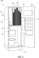
- the beverage vending machine 1000 comprises the housing 101, which includes a body portion 102 and a door 103 that can be closed ( FIG. 1 ) and open ( FIG. 2 ).
- the door 103 is closed during normal use of the beverage vending machine 1000 and open during maintenance and/or when additional cups need to be inserted into the beverage vending machine 1000. Opening and closing of the door 103 can be achieved by an administrator or other authorized individual and may require the use of a key or other device to unlock the housing 101 prior to opening the door 103.
- the beverage vending machine 1000 comprises a user interface 140 on the door 103 of the housing 101.
- the user interface 140 could be located at other positions along the housing 101 in other embodiments.
- the user interface 140 comprises a plurality of buttons 104, each of which includes indicia, graphics, or labeling for a different type of beverage.
- one of the buttons 104 may include a graphic image of a particular type of coffee and another one of the buttons 104 may include a graphic image of hot chocolate, iced or hot tea, plain or flavored water, a type of soup, or the like.
- each of the buttons 104 is associated with one of the types of beverages that the beverage vending machine 1000 is configured to create.
- buttons 104 When a user desires to have a particular beverage created for him or her by the beverage vending machine 1000, the user presses (or otherwise actuates) one of the buttons 104, which causes the beverage vending machine 1000 to create the selected beverage and present a cup containing the selected beverage to the user.
- the user interface 140 may be a touch screen such that the buttons 104 are merely regions on the user interface 140 that can be selected via contact by a user's finger. Alternatively, the buttons 104 may protrude from the door 103 so that they can be pressed for actuation thereof.
- the invention is not to be limited by these examples and the buttons 104 can take on any other form used in beverage vending machines of this type.
- the beverage vending machine 1000 includes a payment receiving section 105 and a coin return area 106.
- the payment receiving section 105 may be configured to receive payment in coins, cash, or electronic payment which may include payment via a credit or debit card or payment via an electronic key that has money associated therewith.
- the beverage vending machine 1000 may be preset to operate without requiring payment in some instances, such as if the beverage vending machine 1000 is located in a place of employment and the employer desires to provide free beverages from the beverage vending machine 1000 as a perk.
- the beverage vending machine 1000 includes a beverage pick-up zone 107 which is where the user/consumer can pick up the beverage after it is made by the beverage vending machine 1000.
- the door 103 can be opened to expose an interior cavity 108 of the beverage vending machine 1000, which houses the cup dispensing assembly 200 and the liquid injection mechanism 150.
- the cup dispensing assembly 200 which will be described in much greater detail below, supports a plurality of stacks of cups 300.
- the cups in each particular stack of cups 300 may be pre-loaded with a beverage ingredient (e.g., coffee grounds, tea leaves, flavored powder, hot cocoa powder, soup base ingredients, or the like).
- a beverage ingredient e.g., coffee grounds, tea leaves, flavored powder, hot cocoa powder, soup base ingredients, or the like.
- the beverage vending machine 1000 will dispense a cup that contains powdered coffee mixed with sugar, and if the user wants a hot cocoa, the beverage vending machine 1000 will dispense a cup that contains cocoa powder, and so on. Because there are multiple stacks of cups 300 each comprising cups that are pre-loaded with a different beverage ingredient, many different beverages can be made with the beverage vending machine 1000. Of course, some of the stacks of cups 300 may not be pre-loaded with any beverage ingredient, particularly those stacks of cups 300 that are designated for preparing water (hot or cold) for the consumer.
- the liquid injection mechanism 150 comprises conduits 109 that are operably coupled to a water supply source (not shown) so that water can be made to flow into the beverage vending machine 1000 for generating a desired beverage.
- the water supply source may be a water main of a water supply system or it may be a filtered water source or the like.
- a cup is dispensed from the cup dispensing assembly 200 and positioned so that liquid can be injected from the liquid injection mechanism 150 into the cup.
- the cup may be pre-loaded with a beverage ingredient (e.g., coffee grounds, tea leaves, flavored powder, hot cocoa powder, or the like) so that upon the injection of a liquid such as water into the cup, the desired beverage is formed.
- the liquid e.g., water
- the liquid may be injected at different temperatures (hot for coffee, tea, and hot chocolate and cold for plain water, flavored water, fruit juices, or the like).
- the beverage vending machine 1000 also includes a processor and/or circuitry 110 that includes all of the electronic components required for proper operation of the beverage vending machine 1000.
- the processor 110 is configured to receive signals indicative of a choice of beverage selected by a consumer and initiate operation of the cup dispensing assembly 200 so that the correct beverage is generated and provided to the consumer, as described in detail herein below.
- the cup dispensing assembly 200 comprises a carousel 290 that comprises a plurality of cup dispensing sections 203.
- the carousel 290 is ring-shaped and each of the cup dispensing sections 203 is a segment or circumferential section of the ring.
- the cup dispensing sections 203 are arranged in a side-by-side manner such that each cup dispensing section 203 is immediately adjacent and positioned between two others of the cup dispensing sections 203.
- Each of the cup dispensing sections 203 comprises a cup dispensing mechanism 201, which is configured to hold a stack of cups and to dispense cups from that stack.
- a cup dispensing mechanism 201 is illustrated to avoid clutter in that particular illustration. It should be appreciated that there is a cup dispensing mechanism 201 located along and associated with each of the cup dispensing sections 203 of the carousel 290.
- the cup dispensing assembly 200 comprises a plurality of the cup dispensing mechanisms 201, in other embodiments the cup dispensing assembly 200 may comprise just a single cup dispensing mechanism 201.
- the carousel 290 is configured to rotate about a rotational axis C-C in the direction of the arrow Z (or the opposite direction) during operation of the beverage vending machine 1000.
- the carousel 290 is moved or rotated about the rotational axis C-C in order to align a desired one of the cup dispensing mechanisms 201 and cup dispensing sections 203 with an actuator mechanism 400 (depicted generically herein) that operates in conjunction with the cup dispensing mechanism 201 with which it is aligned to dispense a cup from the cup dispensing mechanism 201 in accordance with a beverage selection made by a consumer.
- the actuator mechanism 400 is positioned to engage an actuator member (now shown, but see element 239 in FIG. 7 , for example) to initiate a cup dispensing operation.
- the actuator mechanism 400 may not be perfectly circumferentially aligned with the cup dispensing mechanism 201 that it actuates, depending on the particular structure of the actuator member and the actuator mechanism 400.
- the carousel 290 will rotate until the cup dispensing mechanism 201 that is supporting a stack of cups with each cup containing coffee and sugar is aligned with an actuation feature of the actuator mechanism 400. Additional details related to the actuator mechanism 400 and its operation on the cup dispensing mechanisms 201 can be found in GB2402386 published on July 19, 2006 , the entirety of which is incorporated herein by reference.
- the carousel 290 is ring-shaped and comprises an inner surface 291 and an outer surface 281. Ring-shaped may include circular and non-circular shapes in various different embodiments, although the carousel 290 is circular ring-shaped in the exemplified embodiment.
- the inner surface 291 of the carousel 290 surrounds or faces an opening within which additional mechanical components of the beverage vending machine 1000 (such as the actuator mechanism 400) may be positioned.
- the inner surface 291 of the carousel 290 forms a circle having a first diameter and the outer surface 281 of the carousel forms a circle having a second diameter which is greater than the first diameter.
- the stack of cups 300 is depicted being supported by one of the cup dispensing mechanisms 201 and in that cup dispensing mechanism 201 a top plate has been removed to expose the internal components that facilitate the dispensing of an individual cup.
- Each of the cup dispensing mechanisms 201 may support a stack of cups holding a different beverage ingredient, although this is not shown in the drawings to avoid clutter.
- the cups when the cups are inserted into the beverage vending machine 1000, the cups may be pre-filled with a beverage ingredient (e.g., coffee grounds, hot chocolate powder, tea, flavored water powder, soup base ingredients, etc.).
- a beverage ingredient e.g., coffee grounds, hot chocolate powder, tea, flavored water powder, soup base ingredients, etc.
- a cup having the desired beverage ingredient is dispensed from the cup dispensing assembly 200 and then either hot or cold water is added to create the beverage that is then provided to the consumer.
- some of the cups may not have any beverage ingredient so that the can vend plain water.
- one of the cup dispensing mechanisms 201 may support a stack of cups holding a coffee ingredient therein, another of the cup dispensing mechanisms 201 may support a stack of cups holding a mixture of coffee, sugar, and whitener, another of the cup dispensing mechanisms 201 may support a stack of cups holding hot chocolate, still another of the cup dispensing mechanisms 201 may support a stack of cups holding tea, and yet another of the cup dispensing mechanisms 201 may support a stack of cups that is empty (so that it can hold plain water).
- cup dispensing mechanisms 201 may support a stack of cups holding the same ingredient in some embodiments, although each cup dispensing mechanism 201 may support a stack of cups holding different ingredients in other embodiments, depending on the total number of cup dispensing mechanisms 201 available and the total number of beverages desired to be generated by the beverage vending machine 1000. It may be desirable for each cup within a single stack to contain the same beverage ingredient.
- Each of the cup dispensing mechanisms 201 comprises a cup dispensing aperture 202 through which a lowermost cup in the stack of cups 300 is dispensed, a plurality of scrolls 210 that support the stack of cups 300 and dispense the lowermost cup in the stack 300 when desired (i.e., when a user pushes the button to dispense a beverage that is associated with a particular stack of cups), and a ring gear 220 that interacts with the scrolls 210 as described further below to facilitate the dispensing of the cups.
- the plurality of scrolls 210 comprises four scrolls, although more or less than four scrolls could be used in other embodiments.
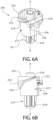
- the four scrolls 210 are similar in structure, and the particular structure of the scrolls 210 will be described in greater detail below with reference to FIGS. 6A and 6B .
- the plurality of scrolls 210 are arranged in pairs including a first pair of scrolls 210a that are positioned adjacent to one another and a second pair of scrolls 210b that are positioned adjacent to one another.
- the first pair of scrolls 210a may be considered the inner scrolls because they are located closer to (i.e., adjacent to) the inner surface 291 of the carousel 290 and the second pair of scrolls 210b may be considered the outer scrolls because they are located closer to (i.e., adjacent to) the outer surface 281 of the carousel 290. Because there are four of the scrolls 210, the scrolls 210 are collectively arranged about (or collectively form) a four-sided polygon with each of the scrolls 210 being positioned on one of the corners of the polygon.
- the first pair of scrolls 210a are spaced apart from one another by a first distance D1 and the second pair of scrolls 210b are spaced apart from one another by a second distance D2 that is greater than the first distance D1.
- the four-sided polygon formed by the scrolls 210 is not a square. More specifically, in the exemplified embodiment the four-sided polygon is a trapezoid, but the invention is not to be limited by this in all embodiments.
- the scrolls 210 all have the same diameter. However, it may be possible for the system described herein to function even with two or more of the scrolls 210 having a different diameter from one another. In embodiments where four scrolls having the same diameter are used (as with the exemplified embodiment), the four-sided polygon could b a square, rectangle, or isosceles trapezium. In other embodiments, the scrolls may have different outside diameters and they may then work when arranged in a convex quadrilateral shape.
- the cup dispensing aperture 202 has a centerpoint CP. Furthermore, there is a reference plane RP1-RP1 that is parallel to a longitudinal axis of the stack of cups 300 and that intersects the centerpoint CP of the cup dispensing aperture 202 so that the first pair of scrolls 210a are located on a first side of the reference plane RP1 and the second pair of scrolls 210b are located on a second side of the reference plane RP1.
- the reference plane RP1-RP1 divides a perimeter of the cup dispensing aperture 202 into a first perimetric portion and a second perimetric portion such that the first pair of scrolls 210a are located along the first perimetric portion and the second pair of scrolls 210b are located along the second perimetric portion. Furthermore, the reference plane RP1-RP1 is positioned between the inner and outer surfaces 291, 281 of the carousel 290 so that the reference plane RP1-RP1 does not intersect the inner and outer surfaces 291, 281 of the carousel 290 along the cup dispensing section 203 at issue.
- each cup dispensing section 203 there is a reference plane RP1 associated with each cup dispensing section 203 and the reference planes RP1 do not intersect the inner and outer surfaces 291, 281 of the carousel 290 within that cup dispensing section 203.
- the reference planes RP1 do not intersect the inner and outer surfaces 291, 281 of the carousel 290 within that cup dispensing section 203.
- the invention is not to be so limited in all embodiments and there could be more or less than four scrolls 210 in other embodiments and the spacing between the scrolls 210 could be modified to be different than that which is shown in the exemplified embodiment in some alternative embodiments.
- the cups of the stack of cups 300 are supported by the scrolls 210 of the cup dispensing mechanisms 201 in a right-side-up orientation. This is necessary in embodiments whereby the cups are pre-loaded with an ingredient, because in such embodiments if the cups were supported upside down or inverted the ingredient would fall out.
- a rim 302 of a lowermost cup 301 in the stack 300 is supported by the scrolls 210 and a portion of the lowermost cup that is below the rim protrudes into and perhaps through the cup dispensing aperture 202.
- FIG. 5 is depicted with arrows on the top of each of the scrolls 210 to illustrate the direction of rotation of each of the scrolls 210 during a cup dispensing operation.
- the first pair of scrolls 210a rotate in a first direction Y
- the second pair of scrolls 210b rotate in a second direction X which is opposite the first direction Y.
- Having the first and second pairs of scrolls 210a, 210b rotate in opposite directions helps to prevent the cups 300 from rotating during the dispensing operation and also prevents the scrolls 210 from damaging the rims of the cups during the dispensing operation, among other advantages. Rather, the scrolls 210 simply push the lowermost cup in the stack downwardly and away from the remainder of the stack so that the lowermost cup can be dispensed during the cup dispensing operation.
- the scrolls of the first pair of scrolls 210a and the scrolls of the second pair of scrolls 210b are essentially identical, except that they may be mirror images of one another. This is due to the fact that the first pair of scrolls 210a and the second pair of scrolls 210b are configured to rotate in opposite directions during dispensing of the lowermost cup 301 from the stack 300, as mentioned above with reference to FIG. 5 and described in greater detail below. Due to the counter rotation of the various scrolls, the features of the scrolls 210 that facilitate the dispensing of the lowermost cup 301 from the stack 300 may need to extend in different directions.
- scrolls 210 will be described generically with reference to FIGS. 6A and 6B , and thus the suffixes "a” and “b” will not be used after the numeral associated with each feature of the scrolls 210.
- the scrolls 210 will be described in terms of their function and relationship with other components of the cup dispensing mechanism 201, with the first and second pairs of scrolls 210a, 210b being described separately from each other because they have different interactions with the ring gear 220.
- the suffixes "a” and “b” may be added to the numerals associated with various features of the scrolls 210 below when the feature being described relates specifically to one of the first or second pairs of scrolls 210a, 210b (specifically, the suffix "a” will be used when describing features that are specific to the first pair of scrolls 210a and the suffix "b” will be used when describing feature that are specific to the second pair of scrolls 210b, although the description of that particular feature provided with reference to FIGS. 6A and 6B will remain applicable unless stated otherwise).
- Each of the scrolls 210 comprises a body portion 218 and a gear portion 211, with the gear portion 211 protruding from a bottom end of the body portion 218.
- the body portion 218 of the scroll 210 comprises a support ledge 212 that is configured to support a rim of a lowermost cup of a stack of cups, thereby supporting the entire stack of cups 300.
- the support ledge 212 also allows for the indexing of the cups in the stack 300.
- the support ledge 212 protrudes from an outer surface 217 of the body portion 218 to achieve this support function and the support ledge 212 may be connected to the body portion 218 in a cantilevered manner.
- the support ledge 212 may be level or planar to facilitate the support of the rim of the cup as described herein. Specifically, referring briefly to FIGS. 4 and 5 , the support ledges 212 of the four scrolls 210 collectively support the stack of cups 300 by the rim 302 of the lowermost cup 301 in the stack of cups 300 resting atop of the support ledges 212 of all of the scrolls 210.
- each of the scrolls 210 also comprises a cup splitter projection 213 protruding from the outer surface 217 of the body portion 218 of the scroll 210.
- the cup splitter projection 213 is configured to force two adjacent cups in a stack of the cups (i.e., the lowermost cup and the second lowermost cup) to separate from one another so that the lowermost cup can be dispensed.
- the cup splitter projection 213 comprises a bottom surface 214 and a top surface 215.
- the top surface 215 of the cup splitter projection 213 is flat and the bottom surface 214 of the cup splitter projection 213 is inclined.
- the bottom surface 214 of the cup splitter projection 213 is oriented oblique to the axis A-A such that the bottom surface 214 of the cup splitter projection 213 extends helically about the outer surface 217 of the body portion 218.
- the cup splitter projection 213 has a tip portion 216, and a height of the cup splitter projection 213 measured between the bottom and top surfaces 214, 215 of the cup splitter projection 213 increases as the cup splitter projection 213 extends circumferentially away from the tip portion 216. This is because the top surface 215 of the cup splitter projection 213 is flat and level (and perpendicular to the axis A-A) whereas the bottom surface 214 of the cup splitter projection 213 is inclined or angled or helical.
- the bottom surface 214 of the cup splitter projection 213 applies a force onto the rim 302 of the lowermost cup 301 to force the lowermost cup 301 to move downwardly and away from the remainder of the stack 300, thereby resulting in the dispensing of the lowermost cup 301 through the cup dispensing aperture 202.
- the cup splitter projection 213 may extend in a different direction on the various scrolls 210.
- the cup splitter projection 213 will appear as shown in FIGS. 6A and 6B such that the height of the cup splitter projection 213 increases when moving clockwise around the scroll 210.
- the cup splitter projection 213 will extend in the opposite direction as that which is shown in FIGS. 6A and 6B , such that the height of the cup splitter projection 213 will increase when moving counterclockwise around the scroll 210.
- each of the scrolls 210 also includes a gear portion 211 protruding from a bottom end of the body portion 218.
- the gear portion 211 comprises a plurality of gear teeth 219 that mesh with or engage with teeth of the ring gear 220 as described in greater detail below to facilitate the rotation of the scrolls 210 during operation to dispense a cup.
- each of the scrolls 210 is rotatable about a rotational axis A-A during this operation, the rotational axes A-A being parallel to each other, to a rotational axis of the ring gear 220, and to the rotational axis C-C of the carousel 290.
- the ring gear 220 is located around the cup dispensing aperture 202, and in some embodiments the ring gear 220 may define the cup dispensing aperture 202.
- the scrolls 210 are arranged around the ring gear 220 so as to be operably coupled to the ring gear 220 so that rotation of the ring gear 220 causes simultaneous rotation of all of the scrolls 210.
- the scrolls 210 are arranged around an outer surface of the ring gear 220 so that the gear portions 211 of the scrolls 210 mesh or engage with teeth on the outer surface of the ring gear 220.
- the ring gear 220 has an inner surface 221 that faces the cup dispensing aperture 202 and an opposite outer surface 222.
- the inner surface 221 of the ring gear 220 is smooth.
- the outer surface 222 of the ring gear 220 comprises a first set of gear teeth 223 and a second set of gear teeth 224 that are configured to interact, either directly or indirectly, with the gear teeth 219 of the gear portions 211 of the scrolls 210.
- first and second sets of gear teeth 223, 224 are located on the outer surface 222 of the ring gear 220 in the exemplified embodiment, the invention is not to be so limited and the first and/or second sets of gear teeth 223, 224 could be located on the inner surface of the ring gear 220 in other embodiments.
- the first and second sets of gear teeth 223, 224 of the ring gear 220 are not located at the same elevation along the ring gear 220.
- the ring gear 220 extends from a first end 225 to a second end 226 in the direction of the rotational axis B-B.
- the first set of gear teeth 223 is located closer to the first end 225 of the ring gear 220 than the second set of gear teeth 224.
- the second set of gear teeth 224 is located closer to the second end 226 of the ring gear 220 than the first set of gear teeth 223.
- the first and second sets of gear teeth 223, 224 are positioned on the ring gear 220 at offset locations in the direction of the rotational axis B-B.
- the ring gear 220 has an upper portion 227 that includes the first end 225 and a lower portion 228 that includes the second end 226.
- the first set of gear teeth 223 are located on the upper portion 227 of the ring gear 220 and the second set of gear teeth 224 are located on the lower portion 228 of the ring gear 220.
- there may be some overlap between the first and second sets of gear teeth 223, 224 such as the embodiment shown in FIGS. 11 , 12A, and 12B described below.
- the scrolls 210 can be identical (other than the helical direction of the cup splitter projection 213 as noted above) while still enabling the ring gear 220 to rotate the first and second pairs of scrolls 210a, 210b in opposite directions.
- the scrolls of the first and second pairs of scrolls 210a, 210b have an identical size and shape in some embodiments.
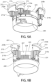
- the gear portions 211 of all of the scrolls 210 are aligned with the upper portion 227 of the ring gear 220, as best seen in FIGS. 9A and 9B .
- the manner in which the counter-rotation of the scrolls is achieved in one exemplary embodiment will be described in greater detail below with reference to FIGS. 9A, 9B , and 10 .
- the rotation direction of the ring gear 220 and the scrolls 210 during a cup dispensing operation will be described.
- the ring gear 220 and each of the scrolls 210 rotate in a particular rotational direction (but not the same direction) during a cup dispensing operation, and then the ring gear 220 and each of the scrolls 210 rotates in the opposite direction after a cup has been dispensed to reset the cup dispensing mechanism 201 and prepare it for the dispensing of the next cup in the stack. That is, the ring gear 220 rotates from a storage position to a dispensing position during a cup dispensing operation, and then rotates back from the dispensing position to the storage position in between cup dispensing operations.
- the ring gear 220 waits in the storage position when the beverage vending machine 1000 is not currently dispensing a cup and vending a beverage.
- the gear ring 220 is made to rotate (via the actuator mechanism 400 shown generically in FIG. 3 and described in greater detail in GB2402386 which has previously been incorporated herein by reference) in a second rotational direction.
- the invention is not to be so limited in all embodiments and the ring gear 220 could alternatively be made to rotate manually by a handle.
- the operable coupling between the gear portions 211 of the first pair of scrolls 210a and the first set of gear teeth 223 of the ring gear 220 causes the scrolls of the first pair of scrolls 210a to rotate in a first rotational direction, which is opposite the second rotational direction.
- the operable coupling between the gear portions 211 of the second pair of scrolls 210b and the second set of gear teeth 224 of the ring gear 220 causes the scrolls of the second pair of scrolls 210b to rotate in the second rotational direction (i.e., in the same direction as the ring gear 220).
- the first rotational direction is clockwise and the second rotational direction is counterclockwise.
- the particular direction (clockwise or counterclockwise) of the first and second rotational directions is dictated, at least in part, by the structure of the scrolls 210 and particularly the helical direction of the cup splitting projections 213 thereof as noted above.
- the ring gear 220 comprises an actuation member 239 that is configured to be operably coupled to the actuator mechanism 400 when it is desired to dispense a cup being supported by the cup dispensing mechanism 201 of which the ring gear 220 is a part.
- the actuator mechanism 400 engages the actuation member 239 of the ring gear 220 and causes it to rotate, thereby causing the entire ring gear 220 to rotate about the rotational axis B-B (when a beverage associated with the particular cup dispensing section 201 is actuated/selected by a user/consumer).
- the first set of gear teeth 223 of the ring gear 220 are operably coupled to the gear teeth 219 of the scrolls 210 of the first pair of scrolls 210a and the second set of gear teeth 224 of the ring gear 220 are operably coupled to the gear teeth 219 of the scrolls 210 of the second pair of scrolls 210b, thereby causing the scrolls 210 to rotate about their own respective rotational axes.
- the rotation of the scrolls 210 causes a lowermost cup of the stack of cups 206 to be separated from the remainder of the stack of cups 206 and thereby dispensed as the cup splitter projections 213 of the scrolls 210 drive a wedge between the lowermost cup and the second lowermost cup.
- the ring gear 220 may be driven by a servo through an idler gear, for example as described in WO01/82249 .
- the actuation member 239 of the ring gear 220 comprises a cam, and the cam is selectively operable by the actuator mechanism 400 positioned outside or inside the carousel 290 (the actuator mechanism 400 is depicted inside the carousel 290 in FIG. 3 , but it could be outside of the carousel 290 in other embodiments).
- the cam-driven ring gear provides the advantages that a single actuator, not mounted to the carousel, can be used to drive the mechanism on any stack. Thus, it is not necessary to have a separate driver for each stack splitting mechanism.
- the actuator mechanism 400 can be arranged so that it does not block the rotation of the carousel 290 that is needed to bring different stacks to the dispensing location.
- the actuator mechanism 400 preferably drives the cam in a reciprocating movement from a storage position (in which the lowermost cup of the stack is supported by the support ledges 212 on the scroll 210 as described above), to a dispensed position (in which the lowermost cup has been dispensed and the next cup in the stack is supported on the top of the cup splitting projection 213), and back to the storage position (in which the previously next cup is now the lowermost cup supported on the support ledge 212).
- the cam projection is situated between the second pair of scrolls 210b, and the cam actuator will then be situated radially outside the carousel.
- the cam projection is situated between the first pair of scrolls 210a, in which case the cam actuator will be situated radially inside the carousel, and the cam projection will normally be situated above or below the plane of the scroll splitters in order to remain clear of the inner scrolls.
- alternative cam-driven mechanisms for rotating the scrolls different from the ring gear, for example a belt-driven mechanism, could be contemplated within the scope of the present invention.
- the carousel 290 of the cup dispensing assembly 200 rotates until the cup dispensing section 201 containing a stack of cups having the beverage ingredient that is associated with the particular beverage selected by the consumer is aligned with the actuator mechanism 400 (shown in FIG. 3 ) of the cup dispensing assembly 200.
- the actuator mechanism 400 will actuate the ring gear 220 of the selected cup dispensing mechanism 201 so that it rotates, which then causes the scrolls 210 of the selected cup dispensing mechanism 201 to rotate, which causes dispensing of one of the cups held within that cup dispensing mechanism 201 of the cup dispensing assembly 200.
- the actuator mechanism 400 may itself be rotated due to an operable coupling to a motor, although the exact manner of activation of the actuator mechanism 400 is not to be limiting in all embodiments of the invention set forth herein.
- FIG. 8A illustrates one of the cup dispensing mechanisms 201 of the cup dispensing assembly 200 whereby the scrolls 210 are supporting the stack of cups 300 on the support ledges 212 thereof. Specifically, a rim 302 of the lowermost cup 301 of the stack of cups 300 rests on the support ledges 212 of the four scrolls 210.
- a bottom portion of the lowermost cup 301 (and some of the other cups in the stack of cups 300) extends through the cup dispensing aperture 202 in the cup dispensing section 201 due to the cups being in a right-side-up orientation as described above.
- the cup dispensing mechanism 201 is in the storage position, which allows the lowermost cup 301 to rest atop the support ledges 212 of the scrolls 210.
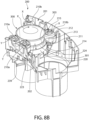
- FIG. 8B the same cup dispensing section 201 of the cup dispensing assembly 200 is illustrated, but in FIG. 8B the ring gear 220 has rotated in the second rotational direction X so that the cup dispensing mechanism 201 is now in the dispensed position. As noted above, this may be achieved by rotating the actuator member 239 of the ring gear 220 with the actuator mechanism 400 (not shown in FIGS. 8A and 8B , but shown and described above).
- the first pair of scrolls 210a have rotated in the first rotational direction Y and the second pair of scrolls 210b have rotated in the second rotational direction X.
- the actuator mechanism causes the ring gear 220 to rotate
- the interaction between the first and second sets of gear teeth 223, 224 of the ring gear 220 and the gear teeth 211 of the scrolls 210 causes the scrolls 210 to also rotate.
- the rim 302 of the lowermost cup 301 is no longer supported by the support ledges 212 of the scrolls 210.
- the stack of cups 300 remains supported by the scrolls 210 because upon this first degree of rotation the rim of the second lowermost cup 303 in the stack of cups 300 rests atop of the top surface 215 of the cup splitter projections 213 of the scrolls 210.
- the lowermost cup 301 remains attached to the second lowermost cup 303 due to friction between the cups, but as can be seen in FIG. 8B the cup splitter projections 213 of the scrolls 210 are driving the lowermost cup 301 downwardly away from the second lowermost cup 303 through the cup dispensing aperture 202.
- the cup splitter projections 213 wedges themselves in between the lowermost cup 301 and the second lowermost cup 303 to force the lowermost cup 301 to separate from the second lowermost cup 303 and be dispensed. Because the bottom surface 214 of the cup splitter projection 213 is angled or helical, rotation of the scrolls 210 causes the lowermost cup 301 to be pushed downwardly away from the second lowermost cup 303.
- the scrolls 210 rotate the distance between the portion of the top surface 215 of the cup splitter projection 213 that supports the second lowermost cup 303 and the portion of the bottom surface 214 of the cup splitter projection 213 that is contacting the lowermost cup 301 increases, which increases the size of the space/distance between the lowermost cup 301 and the second lowermost cup 303.
- the lowermost cup 301 is not supported by the scrolls 210 or any other component of the cup dispensing assembly 200.
- the lowermost cup 301 is dispensed through the cup dispensing aperture 202.
- the ring gear 220 is made to rotate in the opposite direction until the cup dispensing mechanism 201 arrives back at the storage position shown in FIG. 8A .
- the ring gear 220 is rotating in a clockwise direction (the direction X)
- the ring gear 220 rotates in a counter-clockwise direction.
- the direction at which the ring gear 220 rotates could be opposite to that which is described herein with reference to the exemplified embodiment.
- the ring gear 220 is rotated in the opposite direction to "reset" the position of the ring gear 220 and of the scrolls 210 back to the position of FIG. 8A (i.e., the storage position).
- the ring gear 220 and the scrolls 210 rotate back to the initial position whereby the previously denoted second lowermost cup 303 (which is now the lowermost cup because the previously denoted lowermost cup 301 has been dispensed) rests atop of the support ledges 212 of the scrolls 210.
- rotation of the ring gear 220 causes rotation of the scrolls 210 due to the interaction between the first and second sets of gear teeth 223, 224 of the ring gear 220 and the gear teeth 211 of the scrolls 210.
- the ring gear 220 and the scrolls 210 do not rotate a full 360° in accordance with the exemplary embodiment. Rather, the ring gear 220 and the scrolls 210 may rotate up to 300° in some embodiments, or up to any one of 290°, 280°, 270°, 260°, 250°, 240°, 230°, 220°, 210°, 200°, 190°, 180°, 170°, 160°, 150° in other embodiments.
- the ring gear 220 and the scrolls 210 may rotate up to 300° (or any of the other distances) in the first direction during dispensing of the lowermost cup 301, and then the ring gear 220 and the scrolls 210 may rotate up to 300° (or any of the other distances) in a second direction that is opposite the first direction to "reset" back to the non-dispensing position.
- the scrolls 210 may be made to rotate through 360° in a continuous operation, although this may require the use of multiple motors instead of a single motor.
- the manner in which the ring gear 220 is able to rotate the first pair of scrolls 210a in a first rotational direction while simultaneously rotating the second pair of scrolls 210b in a second rotational direction will be described in accordance with an exemplified embodiment of the present invention.
- the bottom surface 214 of the cup splitter projections 213 of the second pair of scrolls 210b extend in an opposite direction to the bottom surface 214 of the cup splitter projections 213 of the first pair of scrolls 210a.
- the cup splitter projections 213 of the first and second pairs of scrolls 210a, 210b will all still operate collectively to split the lowermost cup from the second to the lowermost cup.
- the gear portions 211a of the scrolls of the first pair of scrolls 210a are in direct engagement with the first set of gear teeth 223 of the ring gear 220.
- rotation of the ring gear 220 will directly cause rotation of the first pair of scrolls 210a.
- the ring gear 220 and the scrolls of the first pair of scrolls 210a will rotate in opposite rotational directions. Thus, if the ring gear 220 is rotating in a clockwise direction, then the first pair of scrolls 210a will be rotating in a counterclockwise direction, and vice versa.
- the gear portions 211b of the scrolls of the second pair of scrolls 210b are not in direct engagement with the second set of gear teeth 224 of the ring gear 220. Rather, the gear portions 211b of the scrolls of the second pair of scrolls 210b are aligned with the upper portion 227 of the ring gear 220 between the second set of gear teeth 224 and the first end 225 of the ring gear 220.
- a first idler gear 230 is positioned in direct engagement with the second set of gear teeth 224 of the ring gear 220 and with the gear portion 211b of a first scroll of the second pair of scrolls 210b. Furthermore, a second idler gear 231 is positioned in direct engagement with the second set of gear teeth 224 of the ring gear 220 and the with the gear portion 211b of a second scroll of the second pair of scrolls 210b.
- the second set of scrolls 210b are made to rotate in the opposite rotational direction relative to the first set of scrolls 210a because the ring gear 220 rotates the idler gears 230, 231, which in turn rotates the scrolls of the second set of scrolls 210b.
- rotating the ring gear 220 in a second rotational direction causes the idler gears 230, 231 to rotate in the first rotational direction, which in turn causes the scrolls of the second pair of scrolls 210b to rotate in the second rotational direction.
- the idler gears 230, 231 are in direct mating engagement with the second set of gear teeth 224 of the ring gear 220 and the idler gears 230, 231 are in direct mating engagement with the gear portions 211b of the second pair of scrolls 210b. Furthermore, the gear portions 211b of the second pair of scrolls 210b are not in direct mating engagement with the second set of gear teeth 224 of the ring gear 220 (or any gear teeth of the ring gear 220).
- the first and second idler gears 230, 231 have a height that is greater than the height of the second set of gear teeth 224 of the ring gear 220. This ensures that the first and second idler gears 230, 231 are in mating engagement with the second set of gear teeth 224 of the ring gear 220 and with the gear portions 211b of the second pair of scrolls 210b.
- the idler gears 230, 231 need not have a greater height than the second set of gear teeth 224 in all embodiments and could still be positioned in a manner that ensures its engagement with the second set of gear teeth 224 and with the gear portions 211b of the scrolls 210b.
- the first and second idler gears 230, 231 are located between the scrolls of the second pair of scrolls 210b.
- the spacing between the second pair of scrolls 210b is greater than the spacing between the first pair of scrolls 210a.
- this increased spacing provides ample room for the first and second idler gears 230, 231 to be positioned between the scrolls of the second pair of scrolls 210b.
- the first and second idler gears 230, 231 may be positioned at other locations.
- the scrolls of the second pair of scrolls 210b may be located between the first and second idler gears 230, 231.
- the idler gears 230, 231 are used to facilitate rotation of the second pair of scrolls 210b in a direction that is opposite the rotation direction of the first pair of scrolls 210a.
- the invention is not to be so limited in all embodiments and other techniques may be used to achieve this functionality.
- a chain and sprocket configuration may be used to rotate the first and second pairs of scrolls 210a, 210b in opposite directions.
- first and second pairs of scrolls 210a, 210b may be operably coupled to distinct ring gears such that a first ring gear is operably coupled to the first pair of scrolls 210a to rotate the first pair of scrolls 210a in the first rotational direction while a second ring gear is operably coupled to the second pair of scrolls 210b to rotate the second pair of scrolls 210b in the second rotational direction.
- first pair of scrolls 210a and the second pair of scrolls 210b can be rotated in opposite rotational directions during the cup dispensing operation.
- the scrolls 210 are arranged along a four-side polygon with each of the plurality of scrolls 210 located at one of the corners of the polygon.
- the scrolls 210 located along opposite corners of the polygon that are diagonal from one another rotate in opposite directions.
- the scrolls 210 that are diagonal from one another rotate in opposite directions.
- each scroll is adjacent to one scroll that is rotating in the same direction and one scroll that is rotating in the opposite direction.
- the term "pair of scrolls" as used herein refers to two scrolls that are adjacent to one another and that rotate in the same direction during a particular phase of the cup dispensing operation.
- a ring gear 220a is illustrated in accordance with another embodiment of the present invention.
- the ring gear 220a could be used in the cup dispensing assembly 200 as an alternative to the ring gear 220.
- the ring gear 220a is identical to the ring gear 220 previously described except for the differences noted below.
- the ring gear 220a will be similarly numbered to the ring gear 220, except that the suffix "a" will be used.
- the ring gear 220a comprises a first set of gear teeth 223a and a second set of gear teeth 224a.
- the first set of gear teeth 223a are configured to interact with the first pair of scrolls 210a and the second set of gear teeth 223b are configured to interact with the second pair of scrolls 210b.
- the difference between the ring gear 220a and the ring gear 220 is that the first and second sets of gear teeth 223a, 224a are not at different elevations. However, the first set of gear teeth 223a have a greater height than the second set of gear teeth 224a.
- the first set of gear teeth 223a which interact with the first pair of scrolls 210a have a first height and the second set of gear teeth 224a which interact with the idler gears 230a, 231a, which in turn interact with the second set of scrolls 210b, have a second height which is less than the first height.
- a top end 215a of the first set of gear teeth 223a is aligned or flush with a top end 225a of the ring gear 220a.
- a top end 216a of the second set of gear teeth 224a is offset downwardly relative to the top end 225a of the gear ring 220a. This allows the gear portions 211a of the first set of scrolls 210a to interact with the first set of gear teeth 223a while the gear portions 211b of the second set of scrolls 210b do not directly interact with the second set of gear teeth 224a.
- the interaction between the first pair of scrolls 210a and the first set of gear teeth 223a of the gear ring 220a is illustrated and will be briefly described.
- the gear portions 211a of the first pair of scrolls 210a interact directly with the first set of gear teeth 223a of the gear ring 220a.
- the interaction between the second pair of scrolls 210b and the second set of gear teeth 224a of the gear ring 220a is illustrated and will be briefly described.
- the gear portions 211b of the second pair of scrolls 210b have a reduced height as compared with the gear portions 211a of the first pair of scrolls 2120a. This is to ensure that the gear portions 211b of the second pair of scrolls 210b do not interact directly with the second set of gear teeth 224b of the gear ring 220a.
- first and second idler gears 230a, 231a are used as the intermediary that is operably coupled to both the second set of gear teeth 224b and to the gear portions 211b of the second pair of scrolls 210b.
- the idlers gears 230a, 231 allow the second pair of scrolls 210b to rotate in the same direction as the gear ring 220a, which is the opposite direction that the first pair of scrolls 210a rotate, as described in the previous embodiment.
- the operation is the same as with the previously described embodiment.
- the cup splitters 212 of the scrolls of the first pair of scrolls 210a are mirror images of the cup splitters 212 of the scrolls of the second pair of scrolls 210b.
- the cup splitters 212 of the first pair of scrolls extend helically downwardly in a clockwise direction whereas the cup splitters 212 of the second pair of scrolls 210b extend helically downwardly in a counterclockwise direction.
- the scrolls of the first and second pairs of scrolls 210a, 210b rotate at the same speed (measured in rotations per minute or RPM). The reason for this is that it facilitates pushing the cup equally at all points at the same speed. However, this same function could be achieved by operating the counter rotating scrolls at a different RPM by changing the pitch of the cup splitters 212 in some alternative embodiments.
- the beverage vending machine 1000 may also comprise a brake sub-system 800 for locking the carousel 290 in position and preventing it from moving during the cup dispensing process. More specifically, in the exemplified embodiment the brake sub-system 800 may be activated in both rotational directions of the ring gear 220. This means that the brake sub-system 800 will be activated to lock the carousel 290 in position both when the ring gear 220 moves in a first direction to dispense a lowermost cup from a stack of cups (from the storage position of FIG. 8A to the dispensing position of FIG. 8B ) and when the ring gear 220 moves in a second direction that is opposite the first direction (from the dispensing position of FIG.
- a brake sub-system 800 for locking the carousel 290 in position and preventing it from moving during the cup dispensing process. More specifically, in the exemplified embodiment the brake sub-system 800 may be activated in both rotational directions of the ring gear 220. This means that the brake
- the brake sub-system 800 may be unlocked when none of the cup dispensing mechanisms 201 of the cup dispensing assembly 200 are actively dispensing a cup from a stack or being “reset,” thereby permitting rotation of the carousel 290 when the scrolls 210 and the ring gear 220 are not rotating.
- the reason that this is desirable is that if the carousel 290 is not locked when the scrolls 210 and the ring gear 220 are rotating during a cup dispensing operation, inertia may cause the carousel 290 to move/rotate accidentally as well during the cup dispensing operation. However, this is not desirable because this will result in misalignment between the ring gear 220 and the actuator mechanism 400 which may result in the cup dispensing mechanism 201 failing to properly dispense the lowermost cup from the stack of cups that it is supporting.
- the brake sub-system 800 of the beverage vending machine 1000 is formed by the interaction of the actuator mechanism 400 with the carousel 290.
- the carousel 290 has a plurality of cam lock registers 292, with each cam lock register 292 corresponding to one of the cup dispensing sections 201. That is, there is at least one of the cam lock registers 291 aligned with each of the cup dispensing sections/mechanisms 201 of the cup dispensing assembly 200.
- the cam lock registers 292 are located along the inner surface 291 of the carousel 290. Only a portion of the carousel 290 is illustrated for clarity.
- the cam lock registers 291 comprise a notch or recess as best seen in FIGS. 13 and 14 .
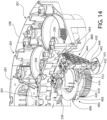
- FIG. 14 illustrates the actuator mechanism 400 and the portion of the carousel 290 as they would appear inside the beverage vending machine 1000.
- the carousel 290 is illustrated showing several of the cup dispensing sections 201 and the respective cam lock registers 292.
- the actuator mechanism 400 comprises a cam assembly 402, the cam assembly 402 comprising an upper cam 420 and a lower cam 410.
- the upper cam 420 has a plurality of upper cam surfaces which, in cooperating with a plurality of lower cam surfaces on the lower cam 410, guide a follower 432 of a lock 430.
- the lower cam 410 has an unlocked surface 412, a ramp surface 414, and a locked surface 418 as best seen in FIG. 15 .
- the upper cam 420 has a corresponding unlocked surface 422, a ramp surface 424, and a locked surface 428 as best seen in FIG. 15 .
- the actuator mechanism 400 further comprises the lock 430 and a guide pin 440.
- the guide pin 440 is configured to enable sliding motion of the lock 430 along the length of the guide pin 440 while preventing rotation of the lock 430 on the guide pin 440.
- the lock 430 In the unlocked state, the lock 430 is proximate a lower end 442 of the guide pin 440.
- the lock 430 In the locked state, the lock 430 is proximate an upper end 444 of the guide pin 440.
- the follower 432 of the lock 430 extends from the guide pin 440 and facilitates the movement of the lock 430 along the guide pin 440. That is, the lock 430 comprises a sheath portion 431 which is positioned around the guide pin 440 and is configured to slide relative to the guide pin 440 and the follower 432 which extends from the sheath portion 431. As discussed previously, the follower 432 rides on the surfaces of the upper cam 420 and lower cam 410 to move the lock 430 from an unlocked state proximate the lower end 442 of the guide pin 440 to a locked state where the lock 430 is moved proximate the upper end 444 of the guide pin 440.
- the lock 430 moves in an upward axial direction when transitioning from the unlocked state to the locked state.
- a locking protrusion 434 of the lock 430 is driven into one of the cam lock register 292 when the lock 430 is moved into the locked state ( FIG. 16 ).
- the carousel 290 is prevented from rotating due to the locking protrusion 434 interfering with any such attempts to rotate the carousel 290.
- the brake sub-system 800 in the locked state as shown in FIG. 16 during a cup dispensing operation, the carousel 290 is prevented from movement during the cup dispensing operation.
- the cup dispensing section 201 immediately to the left of the one which is being engaged/interacted with the lock 430 is the cup dispensing section 201 which is dispensing a cup.
- the lock 430 may interact with the same cup dispensing section 201 which is dispensing a cup.
- the lock 430 may interact with any of the cup dispensing sections 201 of the cup dispensing assembly 200, including the one which is dispensing the cup, the one on either side of the one dispensing the cup, or any of the other cup dispensing sections 201 no matter how close to or how far from the one dispensing the cup they are located.
- the unlocked surfaces 412, 422 of the lower and upper cams 410, 420 dictate the position of the lock 430 when in the unlocked state and can be altered based on the relative positioning of the lock 430 (and particularly the follower 432 thereof) with respect to these surfaces.
- the locked surfaces 418, 428 dictate the position of the lock 430 in the locked state.
- the ramp surfaces 414, 424 control the movement profile and acceleration speeds for a given speed of rotation of the cam assembly 402. In combination, these surfaces can collectively define the total travel of the lock 430 as well as the speed at which the lock 430 moves in and out of the locked state.
- the ramp surfaces 414, 424 need not be flat, and may have a non-linear shape such that they can control the acceleration of the lock 430 as it moves from one state to another.
- the slope can be altered as desired to achieve any desired rate of movement of the lock 430.
- the lock 430 engages the cam lock register 292 corresponding to the cup dispensing section 201 immediately adjacent the cup dispensing section 201 where cups are dispensed.
- the actuator mechanism 400 which is used to activate the scrolls 210 and the actuator mechanism 400 which is used to activate the lock 430 may be different from one another.
- the actuator mechanism 400 which is used to activate the scrolls 210 and the actuator mechanism 400 which is used to activate the lock 430 may be the same device (this is the case in the exemplified embodiment).
- the lock 430 engages the cam lock register 292 of the cup dispensing section 201 immediately clockwise relative to the cup dispensing section 210 from which a cup is being dispensed.
- the cup dispensing section 201 positioned at the lock 430 does not dispense a cup.
- the cup dispensing section 201 which is counterclockwise one position is the cup dispensing section 201 which is operated by the actuator mechanism 400.
- the actuator mechanism 400 first rotates the cam assembly 402 to cause the lock 430 to move from the unlocked state to the locked state. As noted above, this causes the locking protrusion 434 to engage the cam lock register 292 located along the one of the cup dispensing sections 201 which is immediately clockwise of the cup dispensing section 201 containing cups to be dispensed.
- the cam assembly 402 rotates (it may be rotated by a bi-directional motor) a first distance in a first rotational direction (clockwise in the exemplified embodiment), which causes the lower and upper cams 402 to rotate in the first rotational direction.
- the follower 432 rides along the lower and upper cams 410, 420.
- the follower 432 rides from the unlocked surfaces 412, 422, along the ramp surfaces 414, 424, and to the locked surfaces 418, 428.
- the locking protrusion 434 is raised/elevated so that it nests within the cam lock register 292. This is because the locked surfaces 418, 428 are elevated relative to the unlocked surfaces 412, 422, as best seen in FIG. 15 .
- the cam assembly 402 is made to continue rotating in the same direction until an engagement feature 403 of the actuator mechanism 400 engages the actuation member 239 of the ring gear 239.
- the engagement feature 403 of the actuator assembly 400 moves the actuation member 239, which in turn forces the ring gear 220 to rotate to the dispensed position as discussed above (see, for example, FIGS. 8A and 8B ).
- This dispenses a cup by rotating the scrolls 210, as has been discussed in detail above.
- the actuator mechanism 400 moves the actuation member 239 back to the storage position from the dispensed position.
- the actuator mechanism 400 may be coupled to a bi-direction motor (not shown).
- the motor may start to rotate in the opposite direction, which in turn will cause the actuator mechanism 400 and the cam assembly 402 to rotate in the opposite direction.
- the engagement feature 403 will contact the actuation member 239 and move it back to its initial, non-dispensing position (i.e., storage position).
- the cam assembly 402 will then continue to rotate, which will cause the follower 432 to move from being located along the locked surfaces 418, 428 of the lower and upper cams 410, 420 to being located along the unlocked surfaces 412, 422 of the lower and upper cams 410, 420.
- the locking protrusion 434 disengages from the cam lock register 292, so that the carousel 290 can once again be rotated.
- the cam assembly 402 moves the lock 430 from the locked state to the unlocked state. This process ensures that no movement of the carousel 290 can occur during dispensing or when returning to the storage position.
- the brake sub-system 800 is in the locked state at all times during rotation of the scrolls 210.
- the brake sub-system 800 is in the locked state as the scrolls 210 are rotating in a first direction during cup dispensing and also as the scrolls 210 are rotating in a second direction when being reset back to their original position.
- the brake sub-system 800 is in the locked state as the ring gear 220 is rotating in the first direction during cup dispensing and as the ring gear 220 is rotating in the second direction when being reset back to its original position. It is only after completion of all rotation of the ring gear 220 and the scrolls 210 that the brake sub-system 800 alters from the locked state to the unlocked state.
- the cam lock register 292 is shaped as a rectangular recess in the exemplified embodiment, although this is not required in all embodiments and modifications to this shape are possible within the scope of the invention claimed herein.
- the locking protrusion 434 is shaped with angled side surfaces which may be tapered to facilitate alignment during the locking process. Alternately, the cam lock register 292 may have angled surfaces which facilitate alignment or both the cam lock register 292 and the locking protrusion 434 may have angled side surfaces to facilitate alignment.
- the locking protrusion 434 may also take various other shapes such as a cylindrical or conical pin or combinations thereof.
- the cam lock register 292 may be formed as a cylindrical hole or a conical hole, or combinations thereof.
- cam lock register 292 is a notch/recess (female component) and the locking protrusion 434 is a protrusion (male component) in the exemplified embodiment, the opposite may be true in other embodiments.
- the cam lock register 292 may be a protruding feature and the locking protrusion 434 may be a notch or recess that mates with the protruding feature of the cam lock register 292 in other embodiments while achieving the same function.
- the cam lock register 292 and the locking protrusion 434 (and all alternatives thereto as described herein) may be referred to herein as a first locking feature and a second locking feature, respectively.
- the cups of the stacks of cups 300 described herein may be formed from a paper-based material. Such cups may be made out of paper and then lined or coated with plastic or wax to prevent liquid from leaking out or soaking through the paper. The paper material may be recycled paper in some embodiments.
- the paper may not be lined with plastic, because doing so may render the paper cup unable to be recycled in normal paper waste streams.
- the cup may be formed from paper and include a water-based dispersion coating which prevents leaks while still enabling the cup to be recycled in normal paper waste streams.
- vending cups being formed from paper and they could be formed from plastic, polystyrene, polypropylene, polyethylene, polylactic acid, metal, or the like or any other materials typically used to form cups that are intended to hold beverages in other embodiments.
- the cup dispensing assembly 200 may be configured to handle cups having multiple pitches, with the pitch being the distance between rim centers when the cups are stacked. Thus, the pitch need not be consistent throughout the stack for proper dispensing to take place in all embodiments.
- the cups in the stacks 300 may be interlocked (typically done when the cups are plastic) or non-interlocked (used when the cups are paper). Interlocking is some sort of mechanical engagement between adjacent cups that creates a temporary lock therebetween. The machine described herein is able to dispense cups one at a time regardless of whether they are interlocked or not.
- the invention may be directed to a cup dispensing assembly regardless of its end use.
- the cup dispensing assembly 200 may be one that is used in a manufacturing factory such as one that manufactures cups. In such factories, there may be a need to dispense cups at high speed and without distorting said cups during the dispensing.
- the cup dispensing assembly 200 described herein can be used for this purpose and for other purposes and is not limited to use in a beverage vending machine in all embodiments.
Landscapes
- Physics & Mathematics (AREA)
- General Physics & Mathematics (AREA)
- Beverage Vending Machines With Cups, And Gas Or Electricity Vending Machines (AREA)
Description
- 'In Cup' beverage vending machines create a beverage in a disposable cup and then present the disposable cup with the beverage therein to a consumer. Such 'In Cup' beverage vending machines use cups that are pre-filled with powdered ingredients and inject a liquid such as water (and/or milk and sugar) into the cups to form the desired beverage. The cups are typically held inside the machine in multiple stacks to maximize the number of cups that can be stored. The cups themselves are pre-filled with powdered ingredients and stacked one inside the other to facilitate ongoing handling. The cups are typically shipped in wrapped stacks of 20 or more. These stacks are then unwrapped on site and loaded into the machine in columns.
- With certain cups that are stacked in this manner, the stack or one or more cups thereof may rotate when the machine is attempting to dispense a lowermost cup from the stack. The rotation of the stack during the dispensing of the cups may cause the rim of the lowermost cup to climb over the dispensing mechanism. The result of this may be that the lowermost cup is not properly dispensed, or if it is dispensed the rim has been distorted. Thus, a need exists for a beverage vending machine and a cup dispensing mechanism thereof that cures the aforementioned deficiencies.
- Further examples of the prior art are disclosed in the following patent applications published under the following numbers
WO2017/174992 ,GB2394468 WO01/82249 GB2173777 - According to the present invention, there is provided a beverage vending machine as set out in
claim 1. - The invention is directed to a beverage vending machine and a cup dispensing assembly thereof.
- Further areas of applicability of the present invention will become apparent from the detailed description provided hereinafter. It should be understood that the detailed description and specific examples, while indicating the preferred embodiment of the invention, are intended for purposes of illustration only and are not intended to limit the scope of the invention which is defined in the appended claims.
- The present invention will become more fully understood from the detailed description and the accompanying drawings, wherein:
-
FIG. 1 is a perspective view of a beverage vending machine in accordance with an embodiment of the present invention; -
FIG. 2 is a perspective view of the beverage vending machine ofFIG. 1 , wherein a door of a housing thereof is open; -
FIG. 3 is a top plan view of a cup dispensing assembly of the beverage vending machine ofFIG. 1 ; -
FIG. 4 is a perspective view of a portion of the cup dispensing assembly ofFIG. 3 with one of the cup dispensing mechanisms of the cup dispensing assembly supporting a stack of cups; -
FIG. 5 is a close-up view of area V ofFIG. 3 illustrating a cup dispensing mechanism of the cup dispensing assembly; -
FIG. 6A is a perspective view of a scroll of the cup dispensing assembly ofFIG. 3 ; -
FIG. 6B is a front plan view of the scroll ofFIG. 6A ; -
FIG. 7 is a perspective view of a ring gear of the cup dispensing mechanism ofFIG. 5 ; -
FIGS. 8A and8B are perspective views of the cup dispensing mechanism ofFIG. 6 illustrating the operation of the cup dispensing mechanism to dispense a lowermost cup in the stack of cups; and -
FIG. 9A is a perspective view of the ring gear ofFIG. 7 and its interaction with a first pair of scrolls of the cup dispensing mechanism; -
FIG. 9B is a perspective view of the ring gear ofFIG. 7 and its interaction with a second pair of scrolls of the cup dispensing mechanism; -
FIG. 10 is a cross-sectional view taken alone line X-X ofFIG. 9A ; -
FIG. 11 is a perspective view of a ring gear in accordance with another embodiment of the present invention; -
FIG. 12A is a perspective view of the ring gear ofFIG. 11 and its interaction with the first pair of scrolls; -
FIG. 12B is a perspective view of the ring gear ofFIG. 11 and its interaction with the second pair of scrolls; -
FIG. 13 is a perspective view of a portion of a carousel of the cup dispensing assembly ofFIG. 3 showing cam lock registers of a brake sub-system; -
FIG. 14 is a top perspective view of a portion of the cup dispensing assembly ofFIG. 3 showing the brake sub-system in an unlocked state; -
FIG. 15 is a bottom perspective view of a portion of the cup dispensing assembly ofFIG. 3 showing the brake sub-system in an unlocked state; and -
FIG. 16 is a top perspective view of the portion of the cup dispensing assembly ofFIG. 14 showing the brake sub-system in a locked state. - The following description of the preferred embodiment(s) is merely exemplary in nature and is in no way intended to limit the invention, which is defined in the appended claims.
- The description of illustrative embodiments according to principles of the present invention is intended to be read in connection with the accompanying drawings, which are to be considered part of the entire written description.
- Referring to
FIGS. 1 and2 , abeverage vending machine 1000 is illustrated in accordance with an embodiment of the present invention. Thebeverage vending machine 1000 generally comprises ahousing 101, acup dispensing assembly 200, and aliquid injection mechanism 150. Operation of thebeverage vending machine 1000 includes automatic dispensing of one cup from thecup dispensing assembly 200, filling the cup (which may pre-filled with a beverage ingredient) with hot or cold water from theliquid injection mechanism 150 to form a beverage, and presentation of the cup with the beverage therein to a consumer. All of these actions are achieved by thebeverage vending machine 1000 automatically upon a user putting money into the machine (if required) and pressing a button associated with a particular beverage (or otherwise providing an input associated with the particular beverage). Although the description set forth herein relates to the operation of an automatic vending machine, it should be appreciated that the concepts described herein are applicable to manual and automatic vending machines and to other cup dispensing mechanisms even when not associated with a vending machine. - As noted above, the
beverage vending machine 1000 comprises thehousing 101, which includes abody portion 102 and adoor 103 that can be closed (FIG. 1 ) and open (FIG. 2 ). Thedoor 103 is closed during normal use of thebeverage vending machine 1000 and open during maintenance and/or when additional cups need to be inserted into thebeverage vending machine 1000. Opening and closing of thedoor 103 can be achieved by an administrator or other authorized individual and may require the use of a key or other device to unlock thehousing 101 prior to opening thedoor 103. - In the exemplified embodiment, the
beverage vending machine 1000 comprises auser interface 140 on thedoor 103 of thehousing 101. Of course, theuser interface 140 could be located at other positions along thehousing 101 in other embodiments. In the exemplified embodiment, theuser interface 140 comprises a plurality ofbuttons 104, each of which includes indicia, graphics, or labeling for a different type of beverage. For example, one of thebuttons 104 may include a graphic image of a particular type of coffee and another one of thebuttons 104 may include a graphic image of hot chocolate, iced or hot tea, plain or flavored water, a type of soup, or the like. Thus, each of thebuttons 104 is associated with one of the types of beverages that thebeverage vending machine 1000 is configured to create. When a user desires to have a particular beverage created for him or her by thebeverage vending machine 1000, the user presses (or otherwise actuates) one of thebuttons 104, which causes thebeverage vending machine 1000 to create the selected beverage and present a cup containing the selected beverage to the user. Theuser interface 140 may be a touch screen such that thebuttons 104 are merely regions on theuser interface 140 that can be selected via contact by a user's finger. Alternatively, thebuttons 104 may protrude from thedoor 103 so that they can be pressed for actuation thereof. Of course, the invention is not to be limited by these examples and thebuttons 104 can take on any other form used in beverage vending machines of this type. - In the exemplified embodiment, the
beverage vending machine 1000 includes apayment receiving section 105 and acoin return area 106. Thepayment receiving section 105 may be configured to receive payment in coins, cash, or electronic payment which may include payment via a credit or debit card or payment via an electronic key that has money associated therewith. However, thebeverage vending machine 1000 may be preset to operate without requiring payment in some instances, such as if thebeverage vending machine 1000 is located in a place of employment and the employer desires to provide free beverages from thebeverage vending machine 1000 as a perk. Furthermore, thebeverage vending machine 1000 includes a beverage pick-upzone 107 which is where the user/consumer can pick up the beverage after it is made by thebeverage vending machine 1000. - As shown in
FIG. 2 , thedoor 103 can be opened to expose aninterior cavity 108 of thebeverage vending machine 1000, which houses thecup dispensing assembly 200 and theliquid injection mechanism 150. Thecup dispensing assembly 200, which will be described in much greater detail below, supports a plurality of stacks ofcups 300. The cups in each particular stack ofcups 300 may be pre-loaded with a beverage ingredient (e.g., coffee grounds, tea leaves, flavored powder, hot cocoa powder, soup base ingredients, or the like). Thus, once a beverage is selected by a user, thebeverage vending machine 1000 dispenses a cup that is pre-loaded with the beverage ingredient used to make the selected beverage (i.e., the beverage ingredient associated with the selected beverage). For example, if the user wants a hot coffee with sugar, thebeverage vending machine 1000 will dispense a cup that contains powdered coffee mixed with sugar, and if the user wants a hot cocoa, thebeverage vending machine 1000 will dispense a cup that contains cocoa powder, and so on. Because there are multiple stacks ofcups 300 each comprising cups that are pre-loaded with a different beverage ingredient, many different beverages can be made with thebeverage vending machine 1000. Of course, some of the stacks ofcups 300 may not be pre-loaded with any beverage ingredient, particularly those stacks ofcups 300 that are designated for preparing water (hot or cold) for the consumer. - The
liquid injection mechanism 150 comprisesconduits 109 that are operably coupled to a water supply source (not shown) so that water can be made to flow into thebeverage vending machine 1000 for generating a desired beverage. The water supply source may be a water main of a water supply system or it may be a filtered water source or the like. When a desired beverage is selected by a user on theuser interface 140, a cup is dispensed from thecup dispensing assembly 200 and positioned so that liquid can be injected from theliquid injection mechanism 150 into the cup. The cup may be pre-loaded with a beverage ingredient (e.g., coffee grounds, tea leaves, flavored powder, hot cocoa powder, or the like) so that upon the injection of a liquid such as water into the cup, the desired beverage is formed. Depending on the beverage selected on theuser interface 140, the liquid (e.g., water) may be injected at different temperatures (hot for coffee, tea, and hot chocolate and cold for plain water, flavored water, fruit juices, or the like). - In the exemplified embodiment, the
beverage vending machine 1000 also includes a processor and/orcircuitry 110 that includes all of the electronic components required for proper operation of thebeverage vending machine 1000. For example, theprocessor 110 is configured to receive signals indicative of a choice of beverage selected by a consumer and initiate operation of thecup dispensing assembly 200 so that the correct beverage is generated and provided to the consumer, as described in detail herein below. - Referring to
FIG. 3 , a top plan view of thecup dispensing assembly 200 is illustrated. Thecup dispensing assembly 200 comprises acarousel 290 that comprises a plurality ofcup dispensing sections 203. In the exemplified embodiment, thecarousel 290 is ring-shaped and each of thecup dispensing sections 203 is a segment or circumferential section of the ring. Thus, thecup dispensing sections 203 are arranged in a side-by-side manner such that eachcup dispensing section 203 is immediately adjacent and positioned between two others of thecup dispensing sections 203. - Each of the
cup dispensing sections 203 comprises acup dispensing mechanism 201, which is configured to hold a stack of cups and to dispense cups from that stack. InFIG. 3 , only one of thecup dispensing mechanisms 201 is illustrated to avoid clutter in that particular illustration. It should be appreciated that there is acup dispensing mechanism 201 located along and associated with each of thecup dispensing sections 203 of thecarousel 290. Although in the exemplified embodiment, thecup dispensing assembly 200 comprises a plurality of thecup dispensing mechanisms 201, in other embodiments thecup dispensing assembly 200 may comprise just a singlecup dispensing mechanism 201. - In the exemplified embodiment, the
carousel 290 is configured to rotate about a rotational axis C-C in the direction of the arrow Z (or the opposite direction) during operation of thebeverage vending machine 1000. In particular, thecarousel 290 is moved or rotated about the rotational axis C-C in order to align a desired one of thecup dispensing mechanisms 201 andcup dispensing sections 203 with an actuator mechanism 400 (depicted generically herein) that operates in conjunction with thecup dispensing mechanism 201 with which it is aligned to dispense a cup from thecup dispensing mechanism 201 in accordance with a beverage selection made by a consumer. By "aligned" in this sense, it means that theactuator mechanism 400 is positioned to engage an actuator member (now shown, but seeelement 239 inFIG. 7 , for example) to initiate a cup dispensing operation. However, theactuator mechanism 400 may not be perfectly circumferentially aligned with thecup dispensing mechanism 201 that it actuates, depending on the particular structure of the actuator member and theactuator mechanism 400. During operation of thebeverage vending machine 1000, if a user selects coffee with sugar, thecarousel 290 will rotate until thecup dispensing mechanism 201 that is supporting a stack of cups with each cup containing coffee and sugar is aligned with an actuation feature of theactuator mechanism 400. Additional details related to theactuator mechanism 400 and its operation on thecup dispensing mechanisms 201 can be found inGB2402386 published on July 19, 2006 - In the exemplified embodiment the
carousel 290 is ring-shaped and comprises aninner surface 291 and anouter surface 281. Ring-shaped may include circular and non-circular shapes in various different embodiments, although thecarousel 290 is circular ring-shaped in the exemplified embodiment. Theinner surface 291 of thecarousel 290 surrounds or faces an opening within which additional mechanical components of the beverage vending machine 1000 (such as the actuator mechanism 400) may be positioned. Theinner surface 291 of thecarousel 290 forms a circle having a first diameter and theouter surface 281 of the carousel forms a circle having a second diameter which is greater than the first diameter. - In
FIG. 3 , the stack ofcups 300 is depicted being supported by one of thecup dispensing mechanisms 201 and in that cup dispensing mechanism 201 a top plate has been removed to expose the internal components that facilitate the dispensing of an individual cup. Each of thecup dispensing mechanisms 201 may support a stack of cups holding a different beverage ingredient, although this is not shown in the drawings to avoid clutter. As noted above and described further below, when the cups are inserted into thebeverage vending machine 1000, the cups may be pre-filled with a beverage ingredient (e.g., coffee grounds, hot chocolate powder, tea, flavored water powder, soup base ingredients, etc.). Thus, when a beverage is selected by a consumer, a cup having the desired beverage ingredient is dispensed from thecup dispensing assembly 200 and then either hot or cold water is added to create the beverage that is then provided to the consumer. Of course, some of the cups may not have any beverage ingredient so that the can vend plain water. - Thus, for example, one of the
cup dispensing mechanisms 201 may support a stack of cups holding a coffee ingredient therein, another of thecup dispensing mechanisms 201 may support a stack of cups holding a mixture of coffee, sugar, and whitener, another of thecup dispensing mechanisms 201 may support a stack of cups holding hot chocolate, still another of thecup dispensing mechanisms 201 may support a stack of cups holding tea, and yet another of thecup dispensing mechanisms 201 may support a stack of cups that is empty (so that it can hold plain water). Of course, two of thecup dispensing mechanisms 201 may support a stack of cups holding the same ingredient in some embodiments, although eachcup dispensing mechanism 201 may support a stack of cups holding different ingredients in other embodiments, depending on the total number ofcup dispensing mechanisms 201 available and the total number of beverages desired to be generated by thebeverage vending machine 1000. It may be desirable for each cup within a single stack to contain the same beverage ingredient. - Referring to
FIGS. 3-5 concurrently, thecup dispensing mechanisms 201 and their components will be described in greater detail. Each of thecup dispensing mechanisms 201 comprises acup dispensing aperture 202 through which a lowermost cup in the stack ofcups 300 is dispensed, a plurality ofscrolls 210 that support the stack ofcups 300 and dispense the lowermost cup in thestack 300 when desired (i.e., when a user pushes the button to dispense a beverage that is associated with a particular stack of cups), and aring gear 220 that interacts with thescrolls 210 as described further below to facilitate the dispensing of the cups. In the exemplified embodiment, the plurality ofscrolls 210 comprises four scrolls, although more or less than four scrolls could be used in other embodiments. - The four
scrolls 210 are similar in structure, and the particular structure of thescrolls 210 will be described in greater detail below with reference toFIGS. 6A and 6B . In the exemplified embodiment, the plurality ofscrolls 210 are arranged in pairs including a first pair ofscrolls 210a that are positioned adjacent to one another and a second pair ofscrolls 210b that are positioned adjacent to one another. In the exemplified embodiment, the first pair ofscrolls 210a may be considered the inner scrolls because they are located closer to (i.e., adjacent to) theinner surface 291 of thecarousel 290 and the second pair ofscrolls 210b may be considered the outer scrolls because they are located closer to (i.e., adjacent to) theouter surface 281 of thecarousel 290. Because there are four of thescrolls 210, thescrolls 210 are collectively arranged about (or collectively form) a four-sided polygon with each of thescrolls 210 being positioned on one of the corners of the polygon. In the exemplified embodiment, the first pair ofscrolls 210a are spaced apart from one another by a first distance D1 and the second pair ofscrolls 210b are spaced apart from one another by a second distance D2 that is greater than the first distance D1. Thus, in the exemplified embodiment the four-sided polygon formed by thescrolls 210 is not a square. More specifically, in the exemplified embodiment the four-sided polygon is a trapezoid, but the invention is not to be limited by this in all embodiments. - In the exemplified embodiment, the
scrolls 210 all have the same diameter. However, it may be possible for the system described herein to function even with two or more of thescrolls 210 having a different diameter from one another. In embodiments where four scrolls having the same diameter are used (as with the exemplified embodiment), the four-sided polygon could b a square, rectangle, or isosceles trapezium. In other embodiments, the scrolls may have different outside diameters and they may then work when arranged in a convex quadrilateral shape. - In the exemplified embodiment, the
cup dispensing aperture 202 has a centerpoint CP. Furthermore, there is a reference plane RP1-RP1 that is parallel to a longitudinal axis of the stack ofcups 300 and that intersects the centerpoint CP of thecup dispensing aperture 202 so that the first pair ofscrolls 210a are located on a first side of the reference plane RP1 and the second pair ofscrolls 210b are located on a second side of the reference plane RP1. Stated another way, the reference plane RP1-RP1 divides a perimeter of thecup dispensing aperture 202 into a first perimetric portion and a second perimetric portion such that the first pair ofscrolls 210a are located along the first perimetric portion and the second pair ofscrolls 210b are located along the second perimetric portion. Furthermore, the reference plane RP1-RP1 is positioned between the inner andouter surfaces carousel 290 so that the reference plane RP1-RP1 does not intersect the inner andouter surfaces carousel 290 along thecup dispensing section 203 at issue. That is, there is a reference plane RP1 associated with eachcup dispensing section 203 and the reference planes RP1 do not intersect the inner andouter surfaces carousel 290 within thatcup dispensing section 203. When moving along the perimeter of thecup dispensing aperture 202, there are no scrolls located between the two scrolls of the first pair ofscrolls 210a and there are no scrolls located between the two scrolls of the second pair ofscrolls 210b. Rather, the two scrolls of the first pair ofscrolls 210a are located adjacent to one another without any intervening scrolls and the two scrolls of the second pair ofscrolls 210b are located adjacent to one another without any intervening scrolls. - As noted above, although in the exemplified embodiment there are four of the
scrolls 210, the invention is not to be so limited in all embodiments and there could be more or less than fourscrolls 210 in other embodiments and the spacing between thescrolls 210 could be modified to be different than that which is shown in the exemplified embodiment in some alternative embodiments. The cups of the stack ofcups 300 are supported by thescrolls 210 of thecup dispensing mechanisms 201 in a right-side-up orientation. This is necessary in embodiments whereby the cups are pre-loaded with an ingredient, because in such embodiments if the cups were supported upside down or inverted the ingredient would fall out. Thus, in the right-side-up orientation, arim 302 of alowermost cup 301 in thestack 300 is supported by thescrolls 210 and a portion of the lowermost cup that is below the rim protrudes into and perhaps through thecup dispensing aperture 202. -
FIG. 5 is depicted with arrows on the top of each of thescrolls 210 to illustrate the direction of rotation of each of thescrolls 210 during a cup dispensing operation. In particular, the first pair ofscrolls 210a rotate in a first direction Y and the second pair ofscrolls 210b rotate in a second direction X which is opposite the first direction Y. Having the first and second pairs ofscrolls cups 300 from rotating during the dispensing operation and also prevents thescrolls 210 from damaging the rims of the cups during the dispensing operation, among other advantages. Rather, thescrolls 210 simply push the lowermost cup in the stack downwardly and away from the remainder of the stack so that the lowermost cup can be dispensed during the cup dispensing operation. - Referring to
FIGS. 6A and 6B , thescrolls 210 will be described in detail. The scrolls of the first pair ofscrolls 210a and the scrolls of the second pair ofscrolls 210b are essentially identical, except that they may be mirror images of one another. This is due to the fact that the first pair ofscrolls 210a and the second pair ofscrolls 210b are configured to rotate in opposite directions during dispensing of thelowermost cup 301 from thestack 300, as mentioned above with reference toFIG. 5 and described in greater detail below. Due to the counter rotation of the various scrolls, the features of thescrolls 210 that facilitate the dispensing of thelowermost cup 301 from thestack 300 may need to extend in different directions. - The features of the
scrolls 210 will be described generically with reference toFIGS. 6A and 6B , and thus the suffixes "a" and "b" will not be used after the numeral associated with each feature of thescrolls 210. However, later on in this document thescrolls 210 will be described in terms of their function and relationship with other components of thecup dispensing mechanism 201, with the first and second pairs ofscrolls ring gear 220. Thus, the suffixes "a" and "b" may be added to the numerals associated with various features of thescrolls 210 below when the feature being described relates specifically to one of the first or second pairs ofscrolls scrolls 210a and the suffix "b" will be used when describing feature that are specific to the second pair ofscrolls 210b, although the description of that particular feature provided with reference toFIGS. 6A and 6B will remain applicable unless stated otherwise). - Each of the
scrolls 210 comprises abody portion 218 and agear portion 211, with thegear portion 211 protruding from a bottom end of thebody portion 218. Thebody portion 218 of thescroll 210 comprises asupport ledge 212 that is configured to support a rim of a lowermost cup of a stack of cups, thereby supporting the entire stack ofcups 300. Thesupport ledge 212 also allows for the indexing of the cups in thestack 300. Thesupport ledge 212 protrudes from anouter surface 217 of thebody portion 218 to achieve this support function and thesupport ledge 212 may be connected to thebody portion 218 in a cantilevered manner. Thesupport ledge 212 may be level or planar to facilitate the support of the rim of the cup as described herein. Specifically, referring briefly toFIGS. 4 and5 , thesupport ledges 212 of the fourscrolls 210 collectively support the stack ofcups 300 by therim 302 of thelowermost cup 301 in the stack ofcups 300 resting atop of thesupport ledges 212 of all of thescrolls 210. - Referring back to
FIGS. 6A and 6B , each of thescrolls 210 also comprises acup splitter projection 213 protruding from theouter surface 217 of thebody portion 218 of thescroll 210. Thecup splitter projection 213 is configured to force two adjacent cups in a stack of the cups (i.e., the lowermost cup and the second lowermost cup) to separate from one another so that the lowermost cup can be dispensed. Thecup splitter projection 213 comprises abottom surface 214 and atop surface 215. In the exemplified embodiment, thetop surface 215 of thecup splitter projection 213 is flat and thebottom surface 214 of thecup splitter projection 213 is inclined. Specifically, thebottom surface 214 of thecup splitter projection 213 is oriented oblique to the axis A-A such that thebottom surface 214 of thecup splitter projection 213 extends helically about theouter surface 217 of thebody portion 218. Stated another way, thecup splitter projection 213 has atip portion 216, and a height of thecup splitter projection 213 measured between the bottom andtop surfaces cup splitter projection 213 increases as thecup splitter projection 213 extends circumferentially away from thetip portion 216. This is because thetop surface 215 of thecup splitter projection 213 is flat and level (and perpendicular to the axis A-A) whereas thebottom surface 214 of thecup splitter projection 213 is inclined or angled or helical. - Due to the helical nature of the
bottom surface 214 of thecup splitter projection 213, as thescrolls 210 are made to rotate during a cup dispensing operation as described in greater detail below, thebottom surface 214 of thecup splitter projection 213 applies a force onto therim 302 of thelowermost cup 301 to force thelowermost cup 301 to move downwardly and away from the remainder of thestack 300, thereby resulting in the dispensing of thelowermost cup 301 through thecup dispensing aperture 202. Depending on the rotational direction of thescroll 210 during dispensing, thecup splitter projection 213 may extend in a different direction on the various scrolls 210. Thus, for example, if thescroll 210 is made to rotate in a counterclockwise direction during dispensing, thecup splitter projection 213 will appear as shown inFIGS. 6A and 6B such that the height of thecup splitter projection 213 increases when moving clockwise around thescroll 210. However, if thescroll 210 is made to rotate in a clockwise direction during dispensing, thecup splitter projection 213 will extend in the opposite direction as that which is shown inFIGS. 6A and 6B , such that the height of thecup splitter projection 213 will increase when moving counterclockwise around thescroll 210. - As noted above, each of the
scrolls 210 also includes agear portion 211 protruding from a bottom end of thebody portion 218. Thegear portion 211 comprises a plurality ofgear teeth 219 that mesh with or engage with teeth of thering gear 220 as described in greater detail below to facilitate the rotation of thescrolls 210 during operation to dispense a cup. Thus, each of thescrolls 210 is rotatable about a rotational axis A-A during this operation, the rotational axes A-A being parallel to each other, to a rotational axis of thering gear 220, and to the rotational axis C-C of thecarousel 290. - Referring to
FIGS. 4 ,5 , and7 , thering gear 220 will be described in greater detail. Thering gear 220 is located around thecup dispensing aperture 202, and in some embodiments thering gear 220 may define thecup dispensing aperture 202. Thescrolls 210 are arranged around thering gear 220 so as to be operably coupled to thering gear 220 so that rotation of thering gear 220 causes simultaneous rotation of all of thescrolls 210. Thus, in the exemplified embodiment thescrolls 210 are arranged around an outer surface of thering gear 220 so that thegear portions 211 of thescrolls 210 mesh or engage with teeth on the outer surface of thering gear 220. - The
ring gear 220 has aninner surface 221 that faces thecup dispensing aperture 202 and an oppositeouter surface 222. In the exemplified embodiment, theinner surface 221 of thering gear 220 is smooth. Furthermore, theouter surface 222 of thering gear 220 comprises a first set ofgear teeth 223 and a second set ofgear teeth 224 that are configured to interact, either directly or indirectly, with thegear teeth 219 of thegear portions 211 of thescrolls 210. Although the first and second sets ofgear teeth outer surface 222 of thering gear 220 in the exemplified embodiment, the invention is not to be so limited and the first and/or second sets ofgear teeth ring gear 220 in other embodiments. - In the exemplified embodiment, the first and second sets of
gear teeth ring gear 220 are not located at the same elevation along thering gear 220. Specifically, thering gear 220 extends from afirst end 225 to asecond end 226 in the direction of the rotational axis B-B. The first set ofgear teeth 223 is located closer to thefirst end 225 of thering gear 220 than the second set ofgear teeth 224. The second set ofgear teeth 224 is located closer to thesecond end 226 of thering gear 220 than the first set ofgear teeth 223. Thus, the first and second sets ofgear teeth ring gear 220 at offset locations in the direction of the rotational axis B-B. In the exemplified embodiment, there is no overlap between the first set ofgear teeth 223 and the second set ofgear teeth 224. Thus, thering gear 220 has anupper portion 227 that includes thefirst end 225 and alower portion 228 that includes thesecond end 226. The first set ofgear teeth 223 are located on theupper portion 227 of thering gear 220 and the second set ofgear teeth 224 are located on thelower portion 228 of thering gear 220. Stated another way, in the exemplified embodiment there is no reference plane perpendicular to the rotational axis B-B of thering gear 220 that intersects the first set ofgear teeth 223 and the second set ofgear teeth 224. However, in other embodiments there may be some overlap between the first and second sets ofgear teeth FIGS. 11 ,12A, and 12B described below. - By offsetting the location of the first and second sets of
gear teeth scrolls 210 can be identical (other than the helical direction of thecup splitter projection 213 as noted above) while still enabling thering gear 220 to rotate the first and second pairs ofscrolls scrolls gear portions 211 of all of thescrolls 210 are aligned with theupper portion 227 of thering gear 220, as best seen inFIGS. 9A and 9B . The manner in which the counter-rotation of the scrolls is achieved in one exemplary embodiment will be described in greater detail below with reference toFIGS. 9A, 9B , and10 . - Referring again to
FIG. 5 , the rotation direction of thering gear 220 and thescrolls 210 during a cup dispensing operation will be described. Thering gear 220 and each of thescrolls 210 rotate in a particular rotational direction (but not the same direction) during a cup dispensing operation, and then thering gear 220 and each of thescrolls 210 rotates in the opposite direction after a cup has been dispensed to reset thecup dispensing mechanism 201 and prepare it for the dispensing of the next cup in the stack. That is, thering gear 220 rotates from a storage position to a dispensing position during a cup dispensing operation, and then rotates back from the dispensing position to the storage position in between cup dispensing operations. Thering gear 220 waits in the storage position when thebeverage vending machine 1000 is not currently dispensing a cup and vending a beverage. - During a cup dispensing operation, the
gear ring 220 is made to rotate (via theactuator mechanism 400 shown generically inFIG. 3 and described in greater detail inGB2402386 ring gear 220 could alternatively be made to rotate manually by a handle. As thering gear 220 rotates in the second rotational direction, the operable coupling between thegear portions 211 of the first pair ofscrolls 210a and the first set ofgear teeth 223 of thering gear 220 causes the scrolls of the first pair ofscrolls 210a to rotate in a first rotational direction, which is opposite the second rotational direction. Furthermore, as thering gear 220 rotates in the second rotational direction, the operable coupling between thegear portions 211 of the second pair ofscrolls 210b and the second set ofgear teeth 224 of thering gear 220 causes the scrolls of the second pair ofscrolls 210b to rotate in the second rotational direction (i.e., in the same direction as the ring gear 220). In the exemplified embodiment, the first rotational direction is clockwise and the second rotational direction is counterclockwise. However, this could be changed in other embodiments so that the first rotational direction is counterclockwise and the second rotational direction is clockwise. The particular direction (clockwise or counterclockwise) of the first and second rotational directions is dictated, at least in part, by the structure of thescrolls 210 and particularly the helical direction of thecup splitting projections 213 thereof as noted above. - The
ring gear 220 comprises anactuation member 239 that is configured to be operably coupled to theactuator mechanism 400 when it is desired to dispense a cup being supported by thecup dispensing mechanism 201 of which thering gear 220 is a part. Thus, during operation theactuator mechanism 400 engages theactuation member 239 of thering gear 220 and causes it to rotate, thereby causing theentire ring gear 220 to rotate about the rotational axis B-B (when a beverage associated with the particularcup dispensing section 201 is actuated/selected by a user/consumer). As thering gear 220 rotates, the first set ofgear teeth 223 of thering gear 220 are operably coupled to thegear teeth 219 of thescrolls 210 of the first pair ofscrolls 210a and the second set ofgear teeth 224 of thering gear 220 are operably coupled to thegear teeth 219 of thescrolls 210 of the second pair ofscrolls 210b, thereby causing thescrolls 210 to rotate about their own respective rotational axes. The rotation of thescrolls 210 causes a lowermost cup of the stack of cups 206 to be separated from the remainder of the stack of cups 206 and thereby dispensed as thecup splitter projections 213 of thescrolls 210 drive a wedge between the lowermost cup and the second lowermost cup. - The
ring gear 220 may be driven by a servo through an idler gear, for example as described inWO01/82249 actuation member 239 of thering gear 220 comprises a cam, and the cam is selectively operable by theactuator mechanism 400 positioned outside or inside the carousel 290 (theactuator mechanism 400 is depicted inside thecarousel 290 inFIG. 3 , but it could be outside of thecarousel 290 in other embodiments). The cam-driven ring gear provides the advantages that a single actuator, not mounted to the carousel, can be used to drive the mechanism on any stack. Thus, it is not necessary to have a separate driver for each stack splitting mechanism. A further advantage is that theactuator mechanism 400 can be arranged so that it does not block the rotation of thecarousel 290 that is needed to bring different stacks to the dispensing location. Theactuator mechanism 400 preferably drives the cam in a reciprocating movement from a storage position (in which the lowermost cup of the stack is supported by thesupport ledges 212 on thescroll 210 as described above), to a dispensed position (in which the lowermost cup has been dispensed and the next cup in the stack is supported on the top of the cup splitting projection 213), and back to the storage position (in which the previously next cup is now the lowermost cup supported on the support ledge 212). In certain embodiments, the cam projection is situated between the second pair ofscrolls 210b, and the cam actuator will then be situated radially outside the carousel. In other embodiments, the cam projection is situated between the first pair ofscrolls 210a, in which case the cam actuator will be situated radially inside the carousel, and the cam projection will normally be situated above or below the plane of the scroll splitters in order to remain clear of the inner scrolls. It will be appreciated that alternative cam-driven mechanisms for rotating the scrolls, different from the ring gear, for example a belt-driven mechanism, could be contemplated within the scope of the present invention. - Once a particular beverage is selected by a consumer, the
carousel 290 of thecup dispensing assembly 200 rotates until thecup dispensing section 201 containing a stack of cups having the beverage ingredient that is associated with the particular beverage selected by the consumer is aligned with the actuator mechanism 400 (shown inFIG. 3 ) of thecup dispensing assembly 200. Next, theactuator mechanism 400 will actuate thering gear 220 of the selectedcup dispensing mechanism 201 so that it rotates, which then causes thescrolls 210 of the selectedcup dispensing mechanism 201 to rotate, which causes dispensing of one of the cups held within thatcup dispensing mechanism 201 of thecup dispensing assembly 200. Theactuator mechanism 400 may itself be rotated due to an operable coupling to a motor, although the exact manner of activation of theactuator mechanism 400 is not to be limiting in all embodiments of the invention set forth herein. - Referring to
FIGS. 8A and8B , the operation of thecup dispensing assembly 200 to dispense alowermost cup 301 from the stack ofcups 300 will be described.FIG. 8A illustrates one of thecup dispensing mechanisms 201 of thecup dispensing assembly 200 whereby thescrolls 210 are supporting the stack ofcups 300 on thesupport ledges 212 thereof. Specifically, arim 302 of thelowermost cup 301 of the stack ofcups 300 rests on thesupport ledges 212 of the fourscrolls 210. A bottom portion of the lowermost cup 301 (and some of the other cups in the stack of cups 300) extends through thecup dispensing aperture 202 in thecup dispensing section 201 due to the cups being in a right-side-up orientation as described above. InFIG. 8A , thecup dispensing mechanism 201 is in the storage position, which allows thelowermost cup 301 to rest atop thesupport ledges 212 of thescrolls 210. - Referring to
FIG. 8B , the samecup dispensing section 201 of thecup dispensing assembly 200 is illustrated, but inFIG. 8B thering gear 220 has rotated in the second rotational direction X so that thecup dispensing mechanism 201 is now in the dispensed position. As noted above, this may be achieved by rotating theactuator member 239 of thering gear 220 with the actuator mechanism 400 (not shown inFIGS. 8A and8B , but shown and described above). Due to the rotation of thering gear 220 in the second rotational direction (which is clockwise in this embodiment, but could just as easily be counter-clockwise), the first pair ofscrolls 210a have rotated in the first rotational direction Y and the second pair ofscrolls 210b have rotated in the second rotational direction X. Specifically, as the actuator mechanism (not shown in these views) causes thering gear 220 to rotate, the interaction between the first and second sets ofgear teeth ring gear 220 and thegear teeth 211 of the scrolls 210 (either direct or indirect interaction, as described in more detail below) causes thescrolls 210 to also rotate. As thescrolls 210 begin to rotate, therim 302 of thelowermost cup 301 is no longer supported by thesupport ledges 212 of thescrolls 210. However, the stack ofcups 300 remains supported by thescrolls 210 because upon this first degree of rotation the rim of the secondlowermost cup 303 in the stack ofcups 300 rests atop of thetop surface 215 of thecup splitter projections 213 of thescrolls 210. Thelowermost cup 301 remains attached to the secondlowermost cup 303 due to friction between the cups, but as can be seen inFIG. 8B thecup splitter projections 213 of thescrolls 210 are driving thelowermost cup 301 downwardly away from the secondlowermost cup 303 through thecup dispensing aperture 202. - As the
scrolls 210 continue to rotate, thecup splitter projections 213 wedges themselves in between thelowermost cup 301 and the secondlowermost cup 303 to force thelowermost cup 301 to separate from the secondlowermost cup 303 and be dispensed. Because thebottom surface 214 of thecup splitter projection 213 is angled or helical, rotation of thescrolls 210 causes thelowermost cup 301 to be pushed downwardly away from the secondlowermost cup 303. Specifically, as thescrolls 210 rotate the distance between the portion of thetop surface 215 of thecup splitter projection 213 that supports the secondlowermost cup 303 and the portion of thebottom surface 214 of thecup splitter projection 213 that is contacting thelowermost cup 301 increases, which increases the size of the space/distance between thelowermost cup 301 and the secondlowermost cup 303. Eventually, there is insufficient friction between thelowermost cup 301 and the secondlowermost cup 303 for thelowermost cup 301 to remain attached to thestack 300. Furthermore, at this time thelowermost cup 301 is not supported by thescrolls 210 or any other component of thecup dispensing assembly 200. Thus, once a sufficient space is created between thelowermost cup 301 and the secondlowermost cup 303, thelowermost cup 301 is dispensed through thecup dispensing aperture 202. - Although not shown in the drawings, once the
lowermost cup 301 in the stack has been dispensed, thering gear 220 is made to rotate in the opposite direction until thecup dispensing mechanism 201 arrives back at the storage position shown inFIG. 8A . Thus, if during dispensing of thelowermost cup 301 from the stack thering gear 220 is rotating in a clockwise direction (the direction X), then after dispensing of thelowermost cup 301 from the stack thering gear 220 rotates in a counter-clockwise direction. Of course, the direction at which thering gear 220 rotates could be opposite to that which is described herein with reference to the exemplified embodiment. Specifically, thering gear 220 is rotated in the opposite direction to "reset" the position of thering gear 220 and of thescrolls 210 back to the position ofFIG. 8A (i.e., the storage position). Thus, thering gear 220 and thescrolls 210 rotate back to the initial position whereby the previously denoted second lowermost cup 303 (which is now the lowermost cup because the previously denotedlowermost cup 301 has been dispensed) rests atop of thesupport ledges 212 of thescrolls 210. Similar to that which was described above, rotation of thering gear 220 causes rotation of thescrolls 210 due to the interaction between the first and second sets ofgear teeth ring gear 220 and thegear teeth 211 of thescrolls 210. - Thus, the
ring gear 220 and thescrolls 210 do not rotate a full 360° in accordance with the exemplary embodiment. Rather, thering gear 220 and thescrolls 210 may rotate up to 300° in some embodiments, or up to any one of 290°, 280°, 270°, 260°, 250°, 240°, 230°, 220°, 210°, 200°, 190°, 180°, 170°, 160°, 150° in other embodiments. Specifically, thering gear 220 and thescrolls 210 may rotate up to 300° (or any of the other distances) in the first direction during dispensing of thelowermost cup 301, and then thering gear 220 and thescrolls 210 may rotate up to 300° (or any of the other distances) in a second direction that is opposite the first direction to "reset" back to the non-dispensing position. Of course, in alternative embodiments thescrolls 210 may be made to rotate through 360° in a continuous operation, although this may require the use of multiple motors instead of a single motor. - Referring to
FIGS. 9A, 9B , and10 , the manner in which thering gear 220 is able to rotate the first pair ofscrolls 210a in a first rotational direction while simultaneously rotating the second pair ofscrolls 210b in a second rotational direction will be described in accordance with an exemplified embodiment of the present invention. As can be seen by comparing the first pair ofscrolls 210a shown inFIG. 9A to the second pair ofscrolls 210b shown inFIG. 9B , thebottom surface 214 of thecup splitter projections 213 of the second pair ofscrolls 210b extend in an opposite direction to thebottom surface 214 of thecup splitter projections 213 of the first pair ofscrolls 210a. As a result, even though the first pair ofscrolls 210a rotate in an opposite direction than the second pair ofscrolls 210b during a dispensing operation, thecup splitter projections 213 of the first and second pairs ofscrolls - Referring first to
FIGS. 9A and10 concurrently, the operable coupling between thering gear 220 and the first pair ofscrolls 210a will be described. In this embodiment, thegear portions 211a of the scrolls of the first pair ofscrolls 210a are in direct engagement with the first set ofgear teeth 223 of thering gear 220. Thus, due to this direct mating engagement between thegear portions 211a of the scrolls of the first pair ofscrolls 210a and the first set ofgear teeth 223 of thering gear 220, rotation of thering gear 220 will directly cause rotation of the first pair ofscrolls 210a. Furthermore, it should be appreciated that thering gear 220 and the scrolls of the first pair ofscrolls 210a will rotate in opposite rotational directions. Thus, if thering gear 220 is rotating in a clockwise direction, then the first pair ofscrolls 210a will be rotating in a counterclockwise direction, and vice versa. - Referring to
FIGS. 9B and10 , the operable coupling between thering gear 220 and the second pair ofscrolls 210b will be described. In this embodiment, thegear portions 211b of the scrolls of the second pair ofscrolls 210b are not in direct engagement with the second set ofgear teeth 224 of thering gear 220. Rather, thegear portions 211b of the scrolls of the second pair ofscrolls 210b are aligned with theupper portion 227 of thering gear 220 between the second set ofgear teeth 224 and thefirst end 225 of thering gear 220. Therefore, in this embodiment afirst idler gear 230 is positioned in direct engagement with the second set ofgear teeth 224 of thering gear 220 and with thegear portion 211b of a first scroll of the second pair ofscrolls 210b. Furthermore, asecond idler gear 231 is positioned in direct engagement with the second set ofgear teeth 224 of thering gear 220 and the with thegear portion 211b of a second scroll of the second pair ofscrolls 210b. - Thus, the second set of
scrolls 210b are made to rotate in the opposite rotational direction relative to the first set ofscrolls 210a because thering gear 220 rotates the idler gears 230, 231, which in turn rotates the scrolls of the second set ofscrolls 210b. Specifically, rotating thering gear 220 in a second rotational direction causes the idler gears 230, 231 to rotate in the first rotational direction, which in turn causes the scrolls of the second pair ofscrolls 210b to rotate in the second rotational direction. This occurs because the idler gears 230, 231 are in direct mating engagement with the second set ofgear teeth 224 of thering gear 220 and the idler gears 230, 231 are in direct mating engagement with thegear portions 211b of the second pair ofscrolls 210b. Furthermore, thegear portions 211b of the second pair ofscrolls 210b are not in direct mating engagement with the second set ofgear teeth 224 of the ring gear 220 (or any gear teeth of the ring gear 220). - As best seen in
FIG. 9B , in this embodiment the first and second idler gears 230, 231 have a height that is greater than the height of the second set ofgear teeth 224 of thering gear 220. This ensures that the first and second idler gears 230, 231 are in mating engagement with the second set ofgear teeth 224 of thering gear 220 and with thegear portions 211b of the second pair ofscrolls 210b. However, the idler gears 230, 231 need not have a greater height than the second set ofgear teeth 224 in all embodiments and could still be positioned in a manner that ensures its engagement with the second set ofgear teeth 224 and with thegear portions 211b of thescrolls 210b. - Furthermore, in the exemplified embodiment, the first and second idler gears 230, 231 are located between the scrolls of the second pair of
scrolls 210b. As noted above, in the exemplified embodiment the spacing between the second pair ofscrolls 210b is greater than the spacing between the first pair ofscrolls 210a. Thus, this increased spacing provides ample room for the first and second idler gears 230, 231 to be positioned between the scrolls of the second pair ofscrolls 210b. However, in other embodiments the first and second idler gears 230, 231 may be positioned at other locations. For example, in one embodiment the scrolls of the second pair ofscrolls 210b may be located between the first and second idler gears 230, 231. - As noted above, in the exemplified embodiment the idler gears 230, 231 are used to facilitate rotation of the second pair of
scrolls 210b in a direction that is opposite the rotation direction of the first pair ofscrolls 210a. However, the invention is not to be so limited in all embodiments and other techniques may be used to achieve this functionality. For example, in some embodiments a chain and sprocket configuration may be used to rotate the first and second pairs ofscrolls scrolls scrolls 210a to rotate the first pair ofscrolls 210a in the first rotational direction while a second ring gear is operably coupled to the second pair ofscrolls 210b to rotate the second pair ofscrolls 210b in the second rotational direction. Thus, it should be appreciated that there are many different ways that the first pair ofscrolls 210a and the second pair ofscrolls 210b can be rotated in opposite rotational directions during the cup dispensing operation. - As mentioned previously, the
scrolls 210 are arranged along a four-side polygon with each of the plurality ofscrolls 210 located at one of the corners of the polygon. In the embodiments described herein, thescrolls 210 located along opposite corners of the polygon that are diagonal from one another rotate in opposite directions. Thus, thescrolls 210 that are diagonal from one another rotate in opposite directions. Furthermore, each scroll is adjacent to one scroll that is rotating in the same direction and one scroll that is rotating in the opposite direction. The term "pair of scrolls" as used herein refers to two scrolls that are adjacent to one another and that rotate in the same direction during a particular phase of the cup dispensing operation. - Referring to
FIG. 11 , aring gear 220a is illustrated in accordance with another embodiment of the present invention. Thering gear 220a could be used in thecup dispensing assembly 200 as an alternative to thering gear 220. Thering gear 220a is identical to thering gear 220 previously described except for the differences noted below. Thering gear 220a will be similarly numbered to thering gear 220, except that the suffix "a" will be used. Thering gear 220a comprises a first set ofgear teeth 223a and a second set ofgear teeth 224a. The first set ofgear teeth 223a are configured to interact with the first pair ofscrolls 210a and the second set of gear teeth 223b are configured to interact with the second pair ofscrolls 210b. The difference between thering gear 220a and thering gear 220 is that the first and second sets ofgear teeth gear teeth 223a have a greater height than the second set ofgear teeth 224a. - Specifically, the first set of
gear teeth 223a which interact with the first pair ofscrolls 210a have a first height and the second set ofgear teeth 224a which interact with the idler gears 230a, 231a, which in turn interact with the second set ofscrolls 210b, have a second height which is less than the first height. In the exemplified embodiment, atop end 215a of the first set ofgear teeth 223a is aligned or flush with atop end 225a of thering gear 220a. Moreover, a top end 216a of the second set ofgear teeth 224a is offset downwardly relative to thetop end 225a of thegear ring 220a. This allows thegear portions 211a of the first set ofscrolls 210a to interact with the first set ofgear teeth 223a while thegear portions 211b of the second set ofscrolls 210b do not directly interact with the second set ofgear teeth 224a. - Referring to
FIG. 12A , the interaction between the first pair ofscrolls 210a and the first set ofgear teeth 223a of thegear ring 220a is illustrated and will be briefly described. As with the previously described embodiment, thegear portions 211a of the first pair ofscrolls 210a interact directly with the first set ofgear teeth 223a of thegear ring 220a. - Referring to
FIG. 12B , the interaction between the second pair ofscrolls 210b and the second set ofgear teeth 224a of thegear ring 220a is illustrated and will be briefly described. In this embodiment, thegear portions 211b of the second pair ofscrolls 210b have a reduced height as compared with thegear portions 211a of the first pair of scrolls 2120a. This is to ensure that thegear portions 211b of the second pair ofscrolls 210b do not interact directly with the second set of gear teeth 224b of thegear ring 220a. Rather, as with the embodiment previously described, first and second idler gears 230a, 231a are used as the intermediary that is operably coupled to both the second set of gear teeth 224b and to thegear portions 211b of the second pair ofscrolls 210b. The idlers gears 230a, 231 allow the second pair ofscrolls 210b to rotate in the same direction as thegear ring 220a, which is the opposite direction that the first pair ofscrolls 210a rotate, as described in the previous embodiment. Thus, even with the modifiedgear ring 220a and the modifications made to thegear portions 211b of the second pair ofscrolls 210b, the operation is the same as with the previously described embodiment. - As noted above, in the exemplified embodiment the
cup splitters 212 of the scrolls of the first pair ofscrolls 210a are mirror images of thecup splitters 212 of the scrolls of the second pair ofscrolls 210b. Thus, thecup splitters 212 of the first pair of scrolls extend helically downwardly in a clockwise direction whereas thecup splitters 212 of the second pair ofscrolls 210b extend helically downwardly in a counterclockwise direction. In the exemplified embodiment, the scrolls of the first and second pairs ofscrolls cup splitters 212 in some alternative embodiments. - As illustrated in
Figs. 13-16 , thebeverage vending machine 1000 may also comprise abrake sub-system 800 for locking thecarousel 290 in position and preventing it from moving during the cup dispensing process. More specifically, in the exemplified embodiment thebrake sub-system 800 may be activated in both rotational directions of thering gear 220. This means that thebrake sub-system 800 will be activated to lock thecarousel 290 in position both when thering gear 220 moves in a first direction to dispense a lowermost cup from a stack of cups (from the storage position ofFIG. 8A to the dispensing position ofFIG. 8B ) and when thering gear 220 moves in a second direction that is opposite the first direction (from the dispensing position ofFIG. 8B to the storage position ofFIG. 8A ) to "reset" thescrolls 210 as described previously herein. Thebrake sub-system 800 may be unlocked when none of thecup dispensing mechanisms 201 of thecup dispensing assembly 200 are actively dispensing a cup from a stack or being "reset," thereby permitting rotation of thecarousel 290 when thescrolls 210 and thering gear 220 are not rotating. The reason that this is desirable is that if thecarousel 290 is not locked when thescrolls 210 and thering gear 220 are rotating during a cup dispensing operation, inertia may cause thecarousel 290 to move/rotate accidentally as well during the cup dispensing operation. However, this is not desirable because this will result in misalignment between thering gear 220 and theactuator mechanism 400 which may result in thecup dispensing mechanism 201 failing to properly dispense the lowermost cup from the stack of cups that it is supporting. - The
brake sub-system 800 of thebeverage vending machine 1000 is formed by the interaction of theactuator mechanism 400 with thecarousel 290. As best seen inFIG. 13 , thecarousel 290 has a plurality of cam lock registers 292, with each cam lock register 292 corresponding to one of thecup dispensing sections 201. That is, there is at least one of the cam lock registers 291 aligned with each of the cup dispensing sections/mechanisms 201 of thecup dispensing assembly 200. The cam lock registers 292 are located along theinner surface 291 of thecarousel 290. Only a portion of thecarousel 290 is illustrated for clarity. The cam lock registers 291 comprise a notch or recess as best seen inFIGS. 13 and14 . - Turning to
FIGS. 14-16 , thebrake sub-system 800 will be further described.FIG. 14 illustrates theactuator mechanism 400 and the portion of thecarousel 290 as they would appear inside thebeverage vending machine 1000. Thecarousel 290 is illustrated showing several of thecup dispensing sections 201 and the respective cam lock registers 292. Theactuator mechanism 400 comprises acam assembly 402, thecam assembly 402 comprising anupper cam 420 and alower cam 410. Theupper cam 420 has a plurality of upper cam surfaces which, in cooperating with a plurality of lower cam surfaces on thelower cam 410, guide afollower 432 of alock 430. Thelower cam 410 has anunlocked surface 412, aramp surface 414, and a lockedsurface 418 as best seen inFIG. 15 . Theupper cam 420 has a correspondingunlocked surface 422, a ramp surface 424, and a lockedsurface 428 as best seen inFIG. 15 . - The
actuator mechanism 400 further comprises thelock 430 and aguide pin 440. Theguide pin 440 is configured to enable sliding motion of thelock 430 along the length of theguide pin 440 while preventing rotation of thelock 430 on theguide pin 440. In the unlocked state, thelock 430 is proximate alower end 442 of theguide pin 440. In the locked state, thelock 430 is proximate anupper end 444 of theguide pin 440. - The
follower 432 of thelock 430 extends from theguide pin 440 and facilitates the movement of thelock 430 along theguide pin 440. That is, thelock 430 comprises asheath portion 431 which is positioned around theguide pin 440 and is configured to slide relative to theguide pin 440 and thefollower 432 which extends from thesheath portion 431. As discussed previously, thefollower 432 rides on the surfaces of theupper cam 420 andlower cam 410 to move thelock 430 from an unlocked state proximate thelower end 442 of theguide pin 440 to a locked state where thelock 430 is moved proximate theupper end 444 of theguide pin 440. Thus, thelock 430 moves in an upward axial direction when transitioning from the unlocked state to the locked state. A lockingprotrusion 434 of thelock 430 is driven into one of thecam lock register 292 when thelock 430 is moved into the locked state (FIG. 16 ). This prevents rotation of thecarousel 290 until thelock 430 is returned to the unlocked state (FIGS. 14 and15 ). Particularly, as seen inFIG. 16 , when the lockingprotrusion 434 nests within the cam lock register 292 of thecarousel 290, thecarousel 290 is prevented from rotating due to the lockingprotrusion 434 interfering with any such attempts to rotate thecarousel 290. Thus, by having thebrake sub-system 800 in the locked state as shown inFIG. 16 during a cup dispensing operation, thecarousel 290 is prevented from movement during the cup dispensing operation. - In the exemplified embodiment, the locking protrusion (which may be referred to herein as a locking feature) 434 of the
lock 430 engages the cam lock register (which may also be referred to herein as a locking feature) 292 of thecarousel 290 along acup dispensing section 201 of thecup dispensing assembly 200 that is adjacent to thecup dispensing section 201 which is currently dispensing a lowermost cup. For example, in the variation shown inFIGS. 14-16 , thecup dispensing section 201 immediately to the left of the one which is being engaged/interacted with thelock 430 is thecup dispensing section 201 which is dispensing a cup. Of course, the invention is not to be so limited in all embodiments and in other embodiments thelock 430 may interact with the samecup dispensing section 201 which is dispensing a cup. In still other embodiments, thelock 430 may interact with any of thecup dispensing sections 201 of thecup dispensing assembly 200, including the one which is dispensing the cup, the one on either side of the one dispensing the cup, or any of the othercup dispensing sections 201 no matter how close to or how far from the one dispensing the cup they are located. - The
unlocked surfaces upper cams lock 430 when in the unlocked state and can be altered based on the relative positioning of the lock 430 (and particularly thefollower 432 thereof) with respect to these surfaces. Similarly, the lockedsurfaces lock 430 in the locked state. The ramp surfaces 414, 424 control the movement profile and acceleration speeds for a given speed of rotation of thecam assembly 402. In combination, these surfaces can collectively define the total travel of thelock 430 as well as the speed at which thelock 430 moves in and out of the locked state. In particular, the ramp surfaces 414, 424 need not be flat, and may have a non-linear shape such that they can control the acceleration of thelock 430 as it moves from one state to another. Furthermore, the slope can be altered as desired to achieve any desired rate of movement of thelock 430. - In the exemplified embodiment, the
lock 430 engages the cam lock register 292 corresponding to thecup dispensing section 201 immediately adjacent thecup dispensing section 201 where cups are dispensed. In some embodiments theactuator mechanism 400 which is used to activate thescrolls 210 and theactuator mechanism 400 which is used to activate thelock 430 may be different from one another. In another embodiment, theactuator mechanism 400 which is used to activate thescrolls 210 and theactuator mechanism 400 which is used to activate thelock 430 may be the same device (this is the case in the exemplified embodiment). In such an embodiment, in order to provide room for theactuator mechanism 400 to simultaneously actuate theactuation member 239 and lock thecarousel 290, thelock 430 engages the cam lock register 292 of thecup dispensing section 201 immediately clockwise relative to thecup dispensing section 210 from which a cup is being dispensed. Thus, thecup dispensing section 201 positioned at thelock 430 does not dispense a cup. Instead, thecup dispensing section 201 which is counterclockwise one position is thecup dispensing section 201 which is operated by theactuator mechanism 400. - During a dispensing operation, the
actuator mechanism 400 first rotates thecam assembly 402 to cause thelock 430 to move from the unlocked state to the locked state. As noted above, this causes the lockingprotrusion 434 to engage the cam lock register 292 located along the one of thecup dispensing sections 201 which is immediately clockwise of thecup dispensing section 201 containing cups to be dispensed. In particular, during this initial part of the dispensing operation, thecam assembly 402 rotates (it may be rotated by a bi-directional motor) a first distance in a first rotational direction (clockwise in the exemplified embodiment), which causes the lower andupper cams 402 to rotate in the first rotational direction. During this initial part of the dispensing operation, thefollower 432 rides along the lower andupper cams follower 432 rides from theunlocked surfaces surfaces follower 432 is located along the lockedsurfaces protrusion 434 is raised/elevated so that it nests within thecam lock register 292. This is because the lockedsurfaces unlocked surfaces FIG. 15 . - Next, the
cam assembly 402 is made to continue rotating in the same direction until anengagement feature 403 of theactuator mechanism 400 engages theactuation member 239 of thering gear 239. As thecam assembly 402 continues to rotate, theengagement feature 403 of theactuator assembly 400 moves theactuation member 239, which in turn forces thering gear 220 to rotate to the dispensed position as discussed above (see, for example,FIGS. 8A and8B ). This dispenses a cup by rotating thescrolls 210, as has been discussed in detail above. Subsequently, while thelock 430 is still in the locked state, theactuator mechanism 400 moves theactuation member 239 back to the storage position from the dispensed position. That is, as noted above theactuator mechanism 400 may be coupled to a bi-direction motor (not shown). Thus, after thering gear 220 has been rotated to the dispensed position and the cup has been dispensed, the motor may start to rotate in the opposite direction, which in turn will cause theactuator mechanism 400 and thecam assembly 402 to rotate in the opposite direction. In doing so, theengagement feature 403 will contact theactuation member 239 and move it back to its initial, non-dispensing position (i.e., storage position). Thecam assembly 402 will then continue to rotate, which will cause thefollower 432 to move from being located along the lockedsurfaces upper cams unlocked surfaces upper cams follower 432 is aligned with theunlocked surfaces upper cams protrusion 434 disengages from thecam lock register 292, so that thecarousel 290 can once again be rotated. After theactuation member 239 is moved back to the storage position, thecam assembly 402 moves thelock 430 from the locked state to the unlocked state. This process ensures that no movement of thecarousel 290 can occur during dispensing or when returning to the storage position. - It should be appreciated that the
brake sub-system 800 is in the locked state at all times during rotation of thescrolls 210. In particular, thebrake sub-system 800 is in the locked state as thescrolls 210 are rotating in a first direction during cup dispensing and also as thescrolls 210 are rotating in a second direction when being reset back to their original position. Stated another way, thebrake sub-system 800 is in the locked state as thering gear 220 is rotating in the first direction during cup dispensing and as thering gear 220 is rotating in the second direction when being reset back to its original position. It is only after completion of all rotation of thering gear 220 and thescrolls 210 that thebrake sub-system 800 alters from the locked state to the unlocked state. - The
cam lock register 292 is shaped as a rectangular recess in the exemplified embodiment, although this is not required in all embodiments and modifications to this shape are possible within the scope of the invention claimed herein. The lockingprotrusion 434 is shaped with angled side surfaces which may be tapered to facilitate alignment during the locking process. Alternately, thecam lock register 292 may have angled surfaces which facilitate alignment or both thecam lock register 292 and the lockingprotrusion 434 may have angled side surfaces to facilitate alignment. The lockingprotrusion 434 may also take various other shapes such as a cylindrical or conical pin or combinations thereof. Thecam lock register 292 may be formed as a cylindrical hole or a conical hole, or combinations thereof. Any configuration is contemplated which would tolerate some misalignment between thecarousel 290 and thelock 430 and still ensure reliable coupling between thelock 430 and thecarousel 290. Moreover, while thecam lock register 292 is a notch/recess (female component) and the lockingprotrusion 434 is a protrusion (male component) in the exemplified embodiment, the opposite may be true in other embodiments. In particular thecam lock register 292 may be a protruding feature and the lockingprotrusion 434 may be a notch or recess that mates with the protruding feature of thecam lock register 292 in other embodiments while achieving the same function. In some embodiments, thecam lock register 292 and the locking protrusion 434 (and all alternatives thereto as described herein) may be referred to herein as a first locking feature and a second locking feature, respectively. - Conventionally, 'In Cup' vending machines such as the one described herein above (although not limited to this particular machine) have dispensed the desired beverage in a plastic cup. However, there is a current trend to find alternatives to plastic in all industries, including in 'In Cup' beverage vending machines. Thus, for example, there is a desire to use paper cups instead of plastic cups due to the increased recyclability potential for paper versus plastic. Thus, in some embodiments, the cups of the stacks of
cups 300 described herein may be formed from a paper-based material. Such cups may be made out of paper and then lined or coated with plastic or wax to prevent liquid from leaking out or soaking through the paper. The paper material may be recycled paper in some embodiments. - In other embodiments, the paper may not be lined with plastic, because doing so may render the paper cup unable to be recycled in normal paper waste streams. Thus, in some embodiments the cup may be formed from paper and include a water-based dispersion coating which prevents leaks while still enabling the cup to be recycled in normal paper waste streams.
- Of course, the invention is not limited to the vending cups being formed from paper and they could be formed from plastic, polystyrene, polypropylene, polyethylene, polylactic acid, metal, or the like or any other materials typically used to form cups that are intended to hold beverages in other embodiments.
- Moreover, the
cup dispensing assembly 200 may be configured to handle cups having multiple pitches, with the pitch being the distance between rim centers when the cups are stacked. Thus, the pitch need not be consistent throughout the stack for proper dispensing to take place in all embodiments. Furthermore, the cups in thestacks 300 may be interlocked (typically done when the cups are plastic) or non-interlocked (used when the cups are paper). Interlocking is some sort of mechanical engagement between adjacent cups that creates a temporary lock therebetween. The machine described herein is able to dispense cups one at a time regardless of whether they are interlocked or not. - Moreover, in some non-claimed embodiments the invention may be directed to a cup dispensing assembly regardless of its end use. Thus, for example, the
cup dispensing assembly 200 may be one that is used in a manufacturing factory such as one that manufactures cups. In such factories, there may be a need to dispense cups at high speed and without distorting said cups during the dispensing. Thus, thecup dispensing assembly 200 described herein can be used for this purpose and for other purposes and is not limited to use in a beverage vending machine in all embodiments. - While the invention has been described with respect to specific examples including presently preferred modes of carrying out the invention, those skilled in the art will appreciate that structural and functional modifications may be made without departing from the scope of the invention as set forth in the appended claims.
Claims (11)
- A beverage vending machine (1000) comprising:a cup dispensing assembly (200) comprising:at least one cup dispensing mechanism (201), the cup dispensing mechanism (201) comprising a plurality of cup splitting scrolls (210) arranged around a cup dispensing aperture (202), wherein the plurality of cup splitting scrolls (210) are configured to support a stack of cups (300) and dispense a lowermost cup (301) of the stack of cups (300) through the cup dispensing aperture (202) during a cup dispensing operation, the plurality of cup splitting scrolls (210) comprising a first pair of adjacent scrolls (210a) and a second pair of adjacent scrolls (210b); anda ring gear (220, 220a) configured to rotate about a rotational axis (B-B), the ring gear (220, 220a) comprising a first set of gear teeth (223, 223a) and a second set of gear teeth (224, 224a) that is circumferentially spaced apart from the first set of gear teeth (223, 223a);wherein each of the scrolls of the first pair of adjacent scrolls (210a) comprises a gear portion (211a) that is directly coupled to the first set of gear teeth (223, 223a);characterized in that:a first idler gear (230) in direct engagement with the second set of gear teeth (224, 224a) of the ring gear (220, 220a) and with a gear portion (211b) of a first scroll of the second pair of adjacent scrolls (210b); anda second idler gear (231) in direct engagement with the second set of gear teeth (224, 224a) of the ring gear (220, 220a) and with a gear portion (211b) of a second scroll of the second pair of adjacent scrolls (210b);wherein rotation of the ring gear (220, 220a) causes the first pair of adjacent scrolls (210a) to rotate in a first rotational direction and the second pair of adjacent scrolls (210b) to rotate in a second rotational direction that is opposite the first rotational direction during the cup dispensing operation.
- The beverage vending machine (1000) according to claim 1 further comprising a reference plane (RP1) that intersects a centerpoint (CP) of the cup dispensing aperture (202), and wherein the first pair of adjacent scrolls (210a) are located on a first side of the reference plane and the second pair of adjacent scrolls (210b) are located on a second side of the reference plane.
- The beverage vending machine (1000) according to claim 1 or claim 2 wherein the first pair of adjacent scrolls (210a) are spaced apart from one another by a first distance (D1) and the second pair of adjacent scrolls (210b) are spaced apart from one another by a second distance (D2) that is greater than the first distance (D1).
- The beverage vending machine (1000) according to claim 1 wherein the first and second idler gears (230, 231) have a first height and the second set of gear teeth have a second height, the first height being greater than the second height.
- The beverage vending machine (1000) according to claim 1 wherein the first and second idler gears (230, 231) are located between the first and second scrolls of the second pair of adjacent scrolls (210b).
- The beverage vending machine (1000) according to any one of claims 1 to 5 wherein the first set of gear teeth (223a) of the ring gear (220a) have a first height and the second set of gear teeth (224a) of the ring gear (220a) have a second height, the first height being greater than the second height, and wherein the ring gear (220a) extends from a first end to a second end in a direction of the rotational axis (B-B) of the ring gear (220a), a top end of the first set of gear teeth (223a) located closer to the first end than a top end of the second set of gear teeth (224a).
- The beverage vending machine (1000) according to claim 6 wherein the gear portions (211b) of the first and second scrolls of the second pair of adjacent scrolls (210b) have a reduced height as compared with the gear portions (211a) of the first pair of adjacent scrolls (210a).
- The beverage vending machine (1000) according to any one of claims 1 to 7 further comprising a plurality of the cup dispensing mechanisms (201) and an actuator assembly configured for operable coupling, one at a time, to the ring gears (220, 220a) of each of the plurality of cup dispensing mechanisms (200), the actuator assembly configured to rotate a particular one of the ring gears (220, 220a) in response to user selection of a beverage on a user interface of the beverage vending machine (1000) to perform the cup dispensing operation.
- The beverage vending machine (1000) according to any one of claims 1 to 8 wherein the plurality of cup splitting scrolls (210) are arranged along a four-sided polygon with each of the plurality of cup splitting scrolls (210) located at one of the corners of the four-sided polygon, and wherein the cup splitting scrolls (210) located along opposite corners that are diagonal from one another rotate in opposite directions.
- The beverage vending machine (1000) according to any one of claims 1 to 9 wherein the cup dispensing assembly (200) comprises a ring-shaped carousel (290) having an inner surface and an outer surface, and wherein the first pair of adjacent scrolls (210a) are positioned adjacent to the inner surface of the carousel (290) and the second pair of adjacent scrolls (210b) are positioned adjacent to the outer surface of the carousel (290).
- The beverage vending machine (1000) according to claim 10 further comprising a plurality of the cup dispensing mechanisms (201) each comprising a reference plane that intersects a centerpoint of the cup dispensing aperture (202), the reference plane being positioned in between the inner and outer surfaces of the ring-shaped carousel (290) so that the reference plane does not intersect the inner and outer surfaces of the ring-shaped carousel (290) along the cup dispensing mechanism (201), and wherein the first pair of adjacent scrolls (210a) are located on a first side of the reference plane and the second pair of adjacent scrolls (210b) are located on a second side of the reference plane.
Applications Claiming Priority (2)
| Application Number | Priority Date | Filing Date | Title |
|---|---|---|---|
| US201962947232P | 2019-12-12 | 2019-12-12 | |
| PCT/GB2020/053097 WO2021116662A1 (en) | 2019-12-12 | 2020-12-03 | Beverage vending machine, cup dispensing assembly therefor, and related methods |
Publications (2)
| Publication Number | Publication Date |
|---|---|
| EP4073769A1 EP4073769A1 (en) | 2022-10-19 |
| EP4073769B1 true EP4073769B1 (en) | 2025-01-29 |
Family
ID=74130255
Family Applications (1)
| Application Number | Title | Priority Date | Filing Date |
|---|---|---|---|
| EP20838141.8A Active EP4073769B1 (en) | 2019-12-12 | 2020-12-03 | Beverage vending machine, cup dispensing assembly therefor, and related methods |
Country Status (2)
| Country | Link |
|---|---|
| EP (1) | EP4073769B1 (en) |
| WO (1) | WO2021116662A1 (en) |
Families Citing this family (1)
| Publication number | Priority date | Publication date | Assignee | Title |
|---|---|---|---|---|
| FR3143960B1 (en) * | 2022-12-27 | 2025-03-28 | Kodashi | Bulk distribution machine |
Family Cites Families (5)
| Publication number | Priority date | Publication date | Assignee | Title |
|---|---|---|---|---|
| CA1248062A (en) * | 1985-01-23 | 1989-01-03 | Manfred Garbe | Cup dispenser |
| ITPN20000024A1 (en) * | 2000-04-20 | 2001-10-20 | Necta Vending Solutions Spa | AUTOMATIC BEVERAGE DISPENSER WITH PERFECTED GLASS RELEASE MECHANISM |
| GB2394468B (en) * | 2002-10-25 | 2005-10-19 | Kwai Kun Wong | Rotatable cam element |
| GB2402386B (en) | 2003-06-03 | 2006-07-19 | Mars Inc | Dispensing mechanism |
| EP3440643B1 (en) * | 2016-04-06 | 2022-07-20 | Lavazza Professional UK Limited | Dispensing mechanism |
-
2020
- 2020-12-03 WO PCT/GB2020/053097 patent/WO2021116662A1/en not_active Ceased
- 2020-12-03 EP EP20838141.8A patent/EP4073769B1/en active Active
Also Published As
| Publication number | Publication date |
|---|---|
| EP4073769A1 (en) | 2022-10-19 |
| WO2021116662A1 (en) | 2021-06-17 |
Similar Documents
| Publication | Publication Date | Title |
|---|---|---|
| JP7227549B2 (en) | tablet cassette | |
| RU2672828C2 (en) | Treatment unit of the capsule of the device for preparation of beverages | |
| CA1220457A (en) | Beverage dispenser and dispensing process | |
| JPH06119521A (en) | Coin payment device | |
| WO2021116662A1 (en) | Beverage vending machine, cup dispensing assembly therefor, and related methods | |
| HRP20020058A2 (en) | Food product cartridge | |
| EP3440643B1 (en) | Dispensing mechanism | |
| US3283951A (en) | Cup dispenser | |
| EP4300451B1 (en) | Beverage vending machine and related methods | |
| EP1797800A2 (en) | Capsule dispensing apparatus for vending machines, in particular beverage vending machines | |
| EP3334315B1 (en) | A beverage preparation machine with single motor actuation | |
| GB2402386A (en) | Nested cup dispensing mechanism | |
| JP6520192B2 (en) | Dispensing device for raw materials for beverages | |
| TWI702024B (en) | Beverage brewing device | |
| JP6443114B2 (en) | Beverage ingredient dispensing device | |
| JP6447221B2 (en) | Bag container opening device | |
| CN211093429U (en) | Beverage brewing device | |
| JPH0935139A (en) | Detector for automatic vending machine | |
| JP2016150787A (en) | Bag container opening device | |
| KR960005292B1 (en) | Cup Dropping Device of Beverage Vending Machine | |
| TWM590930U (en) | Drink brewing device | |
| KR100705961B1 (en) | Product dispensing device of manual vending machine | |
| EP3991149A1 (en) | Beverage vending system | |
| JP3804374B2 (en) | Vending machine product dispensing device | |
| CN110507186B (en) | Blanking device and beverage machine |
Legal Events
| Date | Code | Title | Description |
|---|---|---|---|
| STAA | Information on the status of an ep patent application or granted ep patent |
Free format text: STATUS: UNKNOWN |
|
| STAA | Information on the status of an ep patent application or granted ep patent |
Free format text: STATUS: THE INTERNATIONAL PUBLICATION HAS BEEN MADE |
|
| PUAI | Public reference made under article 153(3) epc to a published international application that has entered the european phase |
Free format text: ORIGINAL CODE: 0009012 |
|
| STAA | Information on the status of an ep patent application or granted ep patent |
Free format text: STATUS: REQUEST FOR EXAMINATION WAS MADE |
|
| 17P | Request for examination filed |
Effective date: 20220607 |
|
| AK | Designated contracting states |
Kind code of ref document: A1 Designated state(s): AL AT BE BG CH CY CZ DE DK EE ES FI FR GB GR HR HU IE IS IT LI LT LU LV MC MK MT NL NO PL PT RO RS SE SI SK SM TR |
|
| DAV | Request for validation of the european patent (deleted) | ||
| DAX | Request for extension of the european patent (deleted) | ||
| GRAP | Despatch of communication of intention to grant a patent |
Free format text: ORIGINAL CODE: EPIDOSNIGR1 |
|
| STAA | Information on the status of an ep patent application or granted ep patent |
Free format text: STATUS: GRANT OF PATENT IS INTENDED |
|
| RIC1 | Information provided on ipc code assigned before grant |
Ipc: B65G 59/10 20060101ALI20240503BHEP Ipc: G07F 11/24 20060101ALI20240503BHEP Ipc: G07F 13/10 20060101ALI20240503BHEP Ipc: G07F 11/00 20060101AFI20240503BHEP |
|
| INTG | Intention to grant announced |
Effective date: 20240528 |
|
| GRAS | Grant fee paid |
Free format text: ORIGINAL CODE: EPIDOSNIGR3 |
|
| RAP1 | Party data changed (applicant data changed or rights of an application transferred) |
Owner name: LUIGI LAVAZZA S.P.A. |
|
| GRAA | (expected) grant |
Free format text: ORIGINAL CODE: 0009210 |
|
| STAA | Information on the status of an ep patent application or granted ep patent |
Free format text: STATUS: THE PATENT HAS BEEN GRANTED |
|
| AK | Designated contracting states |
Kind code of ref document: B1 Designated state(s): AL AT BE BG CH CY CZ DE DK EE ES FI FR GB GR HR HU IE IS IT LI LT LU LV MC MK MT NL NO PL PT RO RS SE SI SK SM TR |
|
| REG | Reference to a national code |
Ref country code: GB Ref legal event code: FG4D |
|
| REG | Reference to a national code |
Ref country code: CH Ref legal event code: EP |
|
| REG | Reference to a national code |
Ref country code: DE Ref legal event code: R096 Ref document number: 602020045592 Country of ref document: DE |
|
| REG | Reference to a national code |
Ref country code: IE Ref legal event code: FG4D |
|
| P01 | Opt-out of the competence of the unified patent court (upc) registered |
Free format text: CASE NUMBER: APP_6121/2025 Effective date: 20250205 |
|
| REG | Reference to a national code |
Ref country code: NL Ref legal event code: MP Effective date: 20250129 |
|
| PG25 | Lapsed in a contracting state [announced via postgrant information from national office to epo] |
Ref country code: NL Free format text: LAPSE BECAUSE OF FAILURE TO SUBMIT A TRANSLATION OF THE DESCRIPTION OR TO PAY THE FEE WITHIN THE PRESCRIBED TIME-LIMIT Effective date: 20250129 |
|
| PG25 | Lapsed in a contracting state [announced via postgrant information from national office to epo] |
Ref country code: RS Free format text: LAPSE BECAUSE OF FAILURE TO SUBMIT A TRANSLATION OF THE DESCRIPTION OR TO PAY THE FEE WITHIN THE PRESCRIBED TIME-LIMIT Effective date: 20250429 |
|
| PG25 | Lapsed in a contracting state [announced via postgrant information from national office to epo] |
Ref country code: FI Free format text: LAPSE BECAUSE OF FAILURE TO SUBMIT A TRANSLATION OF THE DESCRIPTION OR TO PAY THE FEE WITHIN THE PRESCRIBED TIME-LIMIT Effective date: 20250129 |
|
| PG25 | Lapsed in a contracting state [announced via postgrant information from national office to epo] |
Ref country code: PL Free format text: LAPSE BECAUSE OF FAILURE TO SUBMIT A TRANSLATION OF THE DESCRIPTION OR TO PAY THE FEE WITHIN THE PRESCRIBED TIME-LIMIT Effective date: 20250129 |
|
| PG25 | Lapsed in a contracting state [announced via postgrant information from national office to epo] |
Ref country code: ES Free format text: LAPSE BECAUSE OF FAILURE TO SUBMIT A TRANSLATION OF THE DESCRIPTION OR TO PAY THE FEE WITHIN THE PRESCRIBED TIME-LIMIT Effective date: 20250129 |
|
| REG | Reference to a national code |
Ref country code: LT Ref legal event code: MG9D |
|
| PG25 | Lapsed in a contracting state [announced via postgrant information from national office to epo] |
Ref country code: NO Free format text: LAPSE BECAUSE OF FAILURE TO SUBMIT A TRANSLATION OF THE DESCRIPTION OR TO PAY THE FEE WITHIN THE PRESCRIBED TIME-LIMIT Effective date: 20250429 Ref country code: IS Free format text: LAPSE BECAUSE OF FAILURE TO SUBMIT A TRANSLATION OF THE DESCRIPTION OR TO PAY THE FEE WITHIN THE PRESCRIBED TIME-LIMIT Effective date: 20250529 |
|
| REG | Reference to a national code |
Ref country code: AT Ref legal event code: MK05 Ref document number: 1764240 Country of ref document: AT Kind code of ref document: T Effective date: 20250129 |
|
| PG25 | Lapsed in a contracting state [announced via postgrant information from national office to epo] |
Ref country code: HR Free format text: LAPSE BECAUSE OF FAILURE TO SUBMIT A TRANSLATION OF THE DESCRIPTION OR TO PAY THE FEE WITHIN THE PRESCRIBED TIME-LIMIT Effective date: 20250129 |
|
| PG25 | Lapsed in a contracting state [announced via postgrant information from national office to epo] |
Ref country code: LV Free format text: LAPSE BECAUSE OF FAILURE TO SUBMIT A TRANSLATION OF THE DESCRIPTION OR TO PAY THE FEE WITHIN THE PRESCRIBED TIME-LIMIT Effective date: 20250129 Ref country code: PT Free format text: LAPSE BECAUSE OF FAILURE TO SUBMIT A TRANSLATION OF THE DESCRIPTION OR TO PAY THE FEE WITHIN THE PRESCRIBED TIME-LIMIT Effective date: 20250529 |
|
| PG25 | Lapsed in a contracting state [announced via postgrant information from national office to epo] |
Ref country code: GR Free format text: LAPSE BECAUSE OF FAILURE TO SUBMIT A TRANSLATION OF THE DESCRIPTION OR TO PAY THE FEE WITHIN THE PRESCRIBED TIME-LIMIT Effective date: 20250430 Ref country code: BG Free format text: LAPSE BECAUSE OF FAILURE TO SUBMIT A TRANSLATION OF THE DESCRIPTION OR TO PAY THE FEE WITHIN THE PRESCRIBED TIME-LIMIT Effective date: 20250129 |
|
| PG25 | Lapsed in a contracting state [announced via postgrant information from national office to epo] |
Ref country code: AT Free format text: LAPSE BECAUSE OF FAILURE TO SUBMIT A TRANSLATION OF THE DESCRIPTION OR TO PAY THE FEE WITHIN THE PRESCRIBED TIME-LIMIT Effective date: 20250129 |
|
| PG25 | Lapsed in a contracting state [announced via postgrant information from national office to epo] |
Ref country code: SE Free format text: LAPSE BECAUSE OF FAILURE TO SUBMIT A TRANSLATION OF THE DESCRIPTION OR TO PAY THE FEE WITHIN THE PRESCRIBED TIME-LIMIT Effective date: 20250129 |
|
| PG25 | Lapsed in a contracting state [announced via postgrant information from national office to epo] |
Ref country code: SM Free format text: LAPSE BECAUSE OF FAILURE TO SUBMIT A TRANSLATION OF THE DESCRIPTION OR TO PAY THE FEE WITHIN THE PRESCRIBED TIME-LIMIT Effective date: 20250129 |
|
| PG25 | Lapsed in a contracting state [announced via postgrant information from national office to epo] |
Ref country code: DK Free format text: LAPSE BECAUSE OF FAILURE TO SUBMIT A TRANSLATION OF THE DESCRIPTION OR TO PAY THE FEE WITHIN THE PRESCRIBED TIME-LIMIT Effective date: 20250129 |
|
| PG25 | Lapsed in a contracting state [announced via postgrant information from national office to epo] |
Ref country code: EE Free format text: LAPSE BECAUSE OF FAILURE TO SUBMIT A TRANSLATION OF THE DESCRIPTION OR TO PAY THE FEE WITHIN THE PRESCRIBED TIME-LIMIT Effective date: 20250129 Ref country code: CZ Free format text: LAPSE BECAUSE OF FAILURE TO SUBMIT A TRANSLATION OF THE DESCRIPTION OR TO PAY THE FEE WITHIN THE PRESCRIBED TIME-LIMIT Effective date: 20250129 |
|
| PG25 | Lapsed in a contracting state [announced via postgrant information from national office to epo] |
Ref country code: RO Free format text: LAPSE BECAUSE OF FAILURE TO SUBMIT A TRANSLATION OF THE DESCRIPTION OR TO PAY THE FEE WITHIN THE PRESCRIBED TIME-LIMIT Effective date: 20250129 |
|
| PG25 | Lapsed in a contracting state [announced via postgrant information from national office to epo] |
Ref country code: SK Free format text: LAPSE BECAUSE OF FAILURE TO SUBMIT A TRANSLATION OF THE DESCRIPTION OR TO PAY THE FEE WITHIN THE PRESCRIBED TIME-LIMIT Effective date: 20250129 |
|
| REG | Reference to a national code |
Ref country code: DE Ref legal event code: R097 Ref document number: 602020045592 Country of ref document: DE |
|
| PLBE | No opposition filed within time limit |
Free format text: ORIGINAL CODE: 0009261 |
|
| STAA | Information on the status of an ep patent application or granted ep patent |
Free format text: STATUS: NO OPPOSITION FILED WITHIN TIME LIMIT |
|
| 26N | No opposition filed |
Effective date: 20251030 |
|
| PGFP | Annual fee paid to national office [announced via postgrant information from national office to epo] |
Ref country code: GB Payment date: 20251218 Year of fee payment: 6 |
|
| PGFP | Annual fee paid to national office [announced via postgrant information from national office to epo] |
Ref country code: FR Payment date: 20251218 Year of fee payment: 6 |
|
| PGFP | Annual fee paid to national office [announced via postgrant information from national office to epo] |
Ref country code: DE Payment date: 20251222 Year of fee payment: 6 |
|
| PGFP | Annual fee paid to national office [announced via postgrant information from national office to epo] |
Ref country code: IT Payment date: 20251231 Year of fee payment: 6 |