EP4073368B1 - Platine d'equipements hydrauliques de turbomachine aeronautique - Google Patents
Platine d'equipements hydrauliques de turbomachine aeronautique Download PDFInfo
- Publication number
- EP4073368B1 EP4073368B1 EP20828046.1A EP20828046A EP4073368B1 EP 4073368 B1 EP4073368 B1 EP 4073368B1 EP 20828046 A EP20828046 A EP 20828046A EP 4073368 B1 EP4073368 B1 EP 4073368B1
- Authority
- EP
- European Patent Office
- Prior art keywords
- hydraulic equipment
- pieces
- plate
- intended
- equipment according
- Prior art date
- Legal status (The legal status is an assumption and is not a legal conclusion. Google has not performed a legal analysis and makes no representation as to the accuracy of the status listed.)
- Active
Links
Images

Classifications
-
- F—MECHANICAL ENGINEERING; LIGHTING; HEATING; WEAPONS; BLASTING
- F02—COMBUSTION ENGINES; HOT-GAS OR COMBUSTION-PRODUCT ENGINE PLANTS
- F02C—GAS-TURBINE PLANTS; AIR INTAKES FOR JET-PROPULSION PLANTS; CONTROLLING FUEL SUPPLY IN AIR-BREATHING JET-PROPULSION PLANTS
- F02C7/00—Features, components parts, details or accessories, not provided for in, or of interest apart form groups F02C1/00 - F02C6/00; Air intakes for jet-propulsion plants
- F02C7/32—Arrangement, mounting, or driving, of auxiliaries
-
- F—MECHANICAL ENGINEERING; LIGHTING; HEATING; WEAPONS; BLASTING
- F01—MACHINES OR ENGINES IN GENERAL; ENGINE PLANTS IN GENERAL; STEAM ENGINES
- F01D—NON-POSITIVE DISPLACEMENT MACHINES OR ENGINES, e.g. STEAM TURBINES
- F01D25/00—Component parts, details, or accessories, not provided for in, or of interest apart from, other groups
- F01D25/28—Supporting or mounting arrangements, e.g. for turbine casing
-
- F—MECHANICAL ENGINEERING; LIGHTING; HEATING; WEAPONS; BLASTING
- F15—FLUID-PRESSURE ACTUATORS; HYDRAULICS OR PNEUMATICS IN GENERAL
- F15B—SYSTEMS ACTING BY MEANS OF FLUIDS IN GENERAL; FLUID-PRESSURE ACTUATORS, e.g. SERVOMOTORS; DETAILS OF FLUID-PRESSURE SYSTEMS, NOT OTHERWISE PROVIDED FOR
- F15B15/00—Fluid-actuated devices for displacing a member from one position to another; Gearing associated therewith
- F15B15/20—Other details, e.g. assembly with regulating devices
-
- F—MECHANICAL ENGINEERING; LIGHTING; HEATING; WEAPONS; BLASTING
- F16—ENGINEERING ELEMENTS AND UNITS; GENERAL MEASURES FOR PRODUCING AND MAINTAINING EFFECTIVE FUNCTIONING OF MACHINES OR INSTALLATIONS; THERMAL INSULATION IN GENERAL
- F16H—GEARING
- F16H57/00—General details of gearing
- F16H57/02—Gearboxes; Mounting gearing therein
- F16H2057/02026—Connection of auxiliaries with a gear case; Mounting of auxiliaries on the gearbox
-
- Y—GENERAL TAGGING OF NEW TECHNOLOGICAL DEVELOPMENTS; GENERAL TAGGING OF CROSS-SECTIONAL TECHNOLOGIES SPANNING OVER SEVERAL SECTIONS OF THE IPC; TECHNICAL SUBJECTS COVERED BY FORMER USPC CROSS-REFERENCE ART COLLECTIONS [XRACs] AND DIGESTS
- Y02—TECHNOLOGIES OR APPLICATIONS FOR MITIGATION OR ADAPTATION AGAINST CLIMATE CHANGE
- Y02T—CLIMATE CHANGE MITIGATION TECHNOLOGIES RELATED TO TRANSPORTATION
- Y02T50/00—Aeronautics or air transport
- Y02T50/60—Efficient propulsion technologies, e.g. for aircraft
Definitions
- the present invention relates to the general field of mounting on an aeronautical turbomachine, in particular a turbojet, of the housing for driving accessories and associated hydraulic equipment and it relates more particularly to an equipment plate fixed to a housing of training of accessories to form an accessory system.
- AGB Accessory GearBox
- AGB Accessory GearBox
- Such an accessory drive unit generally comprises one or more gear trains which are rotated by drawing power from a shaft of the turbojet and to which the various accessories are coupled.
- These accessory drive boxes are usually mounted in the fan compartment area of the turbojet engine. They are more precisely suspended from flanges formed on the metal retention casing of this fan compartment.
- optimizing the aerodynamic drag of the nacelle requires, to limit the frontal surface of the nacelle, to position equipment no longer in the nacelle (fan compartment) but in the so-called “core” compartment of the turbojet (see for example the request FR2981986 in the name of the applicant), that is to say an inter-vein compartment which separates the primary flow vein from the secondary flow vein of a turbofan engine.
- the main aim of the present invention is therefore to overcome such a drawback by proposing a hydraulic equipment plate which makes it possible to obtain a reduced footprint in the central compartment of the turbojet and therefore also a reduced weight for all of this equipment.
- Another object of the invention is to propose an accessories system integrating an accessories drive box which has a reduced number of parts compared to current solutions and therefore a lower cost.
- a hydraulic equipment plate of an aeronautical turbomachine comprising pipes for circulating a fluid at the inlet and outlet of each of said hydraulic equipment, a support part of a housing body of each of said equipment hydraulic equipment intended to receive means of fixing to said hydraulic equipment, characterized in that it further comprises a housing body part of at least one of said hydraulic equipment.
- the hydraulic equipment plate intended to be fixed to an accessory drive box further comprises a part intended to be offset relative to the accessory drive box, said offset part of the plate allowing the fixing of hydraulic equipment on its two sides.
- said hydraulic equipment is chosen from the following equipment: a main fuel pump, a fuel meter, a main fuel filter, a fuel heater, a main heat exchanger.
- the housing body part of said hydraulic equipment is a bottom part of a bowl intended to receive a filter cartridge of the filter. It can then also include a differential pressure sensor (Delta/P) of the filter.
- the housing body part of said hydraulic equipment is a lower part of the envelope of the heater or the exchanger intended to receive an exchange matrix . It can then also include a pressure relief valve for the heater or the exchanger, a by-pass for the main heat exchanger.
- the housing body part of said hydraulic equipment is a lower part of the pump body intended to support and guide a drive shaft of the pump.
- the invention also relates to an accessory system comprising a hydraulic equipment plate as mentioned above and an accessory drive box on which the hydraulic equipment plate is advantageously fixed in an offset manner.
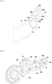
- FIG. 1 shows an accessory drive box 10 mounted in the central compartment (also called “core") of a turbojet and capable of integrating an equipment plate according to the invention.
- core central compartment
- the field of application of the invention may relate to other types of aeronautical turbomachines than a turbojet.
- Such an accessory drive unit drives and supports for example, without this list being exhaustive, one or more electric generators 12, 14, an alternator 16, a lubrication group 18, a starter 20, a oil separator 22 and other components (for example a hydraulic pump 24) which constitute the auxiliary equipment of the engine and power generation of the aircraft.
- the housing 10 is coupled to the rotor 26 of the turbomachine, via a radial power transmission shaft 28 via an angle return box 30.
- the accessory drive housing 10 is typically suspended from a engine casing (not shown) via suspension rods 32, 34.
- such a housing comprises one or more gear trains 36 which are each composed of several toothed wheels and which are rotated by the radial power transmission shaft 28 coupled to the rotor 26 of the turbomachine.
- Each accessory is generally mounted against one of the substantially flat side faces 10A, 10B of the housing 10 and comprises a drive shaft (for example 18A) which then couples to one of the toothed wheels (for example 36A). of the gear train(s).
- these side faces also provide a bearing support, sealing or even lubrication function.
- part of the mechanical power generated is taken from the rotor 26 of the turbomachine and transmitted via the power transmission shaft 28 and the gear train(s) 36 to the power shafts of the different accessories mounted on the housing 10 to cause them to rotate and thus activate the function for which each of the accessories is intended.
- the fuel equipment is mounted on an independent plate 40 having two opposite faces 40A, 40B and one face of which is fixed in part to one end of a side face of the accessory drive box 10 by means of fixing 42 of bolt type for example, a part of this plate being offset outside this accessory drive box and can therefore receive equipment on its two faces (see the Figure 3 ).
- the main fuel pump 44 also called MFP for “Main Fuel Pump”
- the fuel meter 46 also called FMU for “Fuel Metering Unit”
- the main fuel filter 48 also known as MFF for “Main Fuel Filter”
- the fuel heater 50 also known as SFH for “Servo Fuel Heater”
- the main heat exchanger 52 also known as MHX for “Main Heat exchanger”
- the differential pressure sensor (Delta/P) of the fuel filter 54 also known as FFDP for "Fuel Filter Differential Pressure sensor
- this sensor is an independent piece of equipment and not an element of equipment , in this case the filter, unlike the pressure relief valve or the by-pass, mentioned next.
- the other aforementioned equipment 46-54 has the particularity of not requiring such drive and therefore power distribution from the shaft of the turbomachine 26.
- FIG. 4 illustrates more particularly the plate 40 integrating all or part of this equipment at the level of its interfaces with this equipment.
- the plate integrates, in addition to the pipes (not shown) for circulating the fluid at the inlet and at the metering outlet, a 46A support (visible on the figure 2 ) of the body of this doser intended to receive the plate/doser fixing means 46B.
- the plate also integrates the pipes 48A for circulating the fluid at the inlet and outlet for the filter cartridge of the filter and a support 48B for the body of this filter intended to receive the 48C plate/filter fixing means (visible on the figure 2 ).
- the plate also integrates a body part of this 48D filter (visible on the figure 2 ), namely the bottom of the bowl intended to receive the filter cartridge as well as the delta/P 54 sensor. This transfer into the plate of part of the fuel filter function, and the integration into the plate of the function of the Delta/P sensor, contribute significantly to the mass gain.
- the plate integrates, in addition to the pipes 50B for circulating the fluid at the inlet and outlet of the heater and a support 50C of the body of this heater intended to receive the plate fixing means /50D heater (visible on the figure 2 ), a body part of this heater, namely the lower part of the casing 50E (visible on the figure 2 ) of the heater intended to receive the exchange matrix of this heater as well as its 50A relief valve.
- the plate integrates, in addition to the pipes 52C for circulating the fluid at the inlet and outlet of the exchanger and a support 52D (visible on the figure 2 ) of the body of this exchanger intended to receive the plate/exchanger fixing means 52E (visible on the figure 2 ), a body part of this exchanger, namely the lower part of the envelope 52F (visible on the figure 2 ) of the exchanger intended to receive its exchange matrix as well as its pressure relief valve 52A as well as its by-pass 52B.
- the plate 40 integrates, in addition to the pipes 44A for circulating the fluid at the inlet and outlet of the pump, a support 44B (visible on the figure 2 ) of the pump body intended for receive the plate/pump fixing means 44C (visible on the figure 2 ). Note that this plate 40 is crossed by the drive shaft 44D of the pump (visible on the exploded part of the figure 2 ), and that it thus ensures the centering (support and guidance) of this shaft 44D intended to be connected to a pinion of the accessories box 1 0.
Landscapes
- Engineering & Computer Science (AREA)
- Chemical & Material Sciences (AREA)
- Combustion & Propulsion (AREA)
- Mechanical Engineering (AREA)
- General Engineering & Computer Science (AREA)
- Structures Of Non-Positive Displacement Pumps (AREA)
- General Details Of Gearings (AREA)
- Supports For Pipes And Cables (AREA)
- Physics & Mathematics (AREA)
- Fluid Mechanics (AREA)
Description
- La présente invention se rapporte au domaine général du montage sur une turbomachine aéronautique, en particulier un turboréacteur, du boîtier pour l'entraînement d'accessoires et des équipements hydrauliques associés et elle concerne plus particulièrement une platine d'équipements fixée à un boîtier d'entrainement d'accessoires pour former un système d'accessoires.
- Dans un turboréacteur, les accessoires tels que les pompes pour la production d'énergie hydraulique, l'alimentation en carburant et la lubrification, les générateurs électriques pour la production de puissance électrique, etc. sont regroupés au sein d'un boîtier d'entrainement (ou de relais) d'accessoires communément appelé AGB (pour « Accessory GearBox ») qui est en outre entouré de différents équipements nécessaires à l'alimentation et l'asservissement en carburant ou en huile de la turbomachine mais sans liaison mécanique avec l'AGB. Un tel boîtier d'entrainement d'accessoires comprend généralement un ou plusieurs des trains d'engrenages qui sont entraînés en rotation par un prélèvement de puissance sur un arbre du turboréacteur et sur lesquels viennent se coupler les différents accessoires.
- Des boîtiers d'entraînement d'accessoires de l'art antérieur sont divulgués dans les documents
US2012/117982 A1 ,WO2013/001238 A1 ,WO2010/086422 A1 etEP2098757 A2 . - Ces boîtiers d'entrainement d'accessoires sont généralement montés dans la zone du compartiment de soufflante du turboréacteur. Ils sont plus précisément suspendus à des brides formées sur le carter métallique de rétention de ce compartiment de soufflante.
- En outre, l'optimisation de la trainée aérodynamique de la nacelle impose, pour limiter la surface frontale de la nacelle, de positionner des équipements non plus dans la nacelle (compartiment de soufflante) mais dans le compartiment dit « core » du turboréacteur (voir par exemple la demande
FR2981986 - Toutefois, l'installation de l'ensemble des équipements qui possèdent ou non des parties entraînées en rotation par le boîtier d'entrainement d'accessoires pose encore un problème d'encombrement de ces équipements autour de ce boitier. C'est le cas en particulier des équipements carburant, c'est-à-dire les équipements qui sont typiquement affectés au circuit de carburant du turboréacteur.
- La présente invention a donc pour but principal de pallier un tel inconvénient en proposant une platine d'équipements hydrauliques qui permette d'obtenir un encombrement réduit dans le compartiment central du turboréacteur et donc un poids également réduit pour l'ensemble de ces équipements. Un autre objet de l'invention est de proposer un système d'accessoires intégrant un boitier d'entrainement d'accessoires qui présente un nombre de pièces réduit par rapport aux solutions actuelles et donc un coût moindre.
- Ce but est atteint grâce à une platine d'équipements hydrauliques d'une turbomachine aéronautique comportant des canalisations de circulation d'un fluide en entrée et en sortie de chacun desdits équipements hydrauliques, une partie support d'un corps de boitier de chacun desdits équipements hydrauliques destiné à recevoir des moyens de fixation auxdits équipements hydrauliques, caractérisée en ce qu'elle comprend en outre une partie de corps de boitier de l'un au moins desdits équipements hydrauliques.
- Selon un mode de réalisation avantageux, la platine d'équipements hydrauliques destinée à être fixée à un boitier d'entrainement d'accessoires, comporte en outre une partie destinée à être déportée par rapport au boitier d'entrainement d'accessoires, ladite partie déportée de la platine permettant la fixation d'équipements hydrauliques sur ses deux faces.
- De préférence, lesdits équipements hydrauliques sont choisis parmi les équipements suivants : une pompe à carburant principale, un doseur de carburant, un filtre à carburant principal, un réchauffeur de carburant, un échangeur de chaleur principal. Lorsqu'elle comporte au moins le filtre à carburant principal, la partie de corps de boitier dudit équipement hydraulique est une partie de fond d'un bol destiné à recevoir une cartouche filtrante du filtre. Elle peut alors aussi comporter un capteur à pression différentielle (Delta/P) du filtre.
- Lorsqu'elle comporte au moins le réchauffeur de carburant ou l'échangeur de chaleur principal, la partie de corps de boitier dudit équipement hydraulique est une partie inférieure de l'enveloppe du réchauffeur ou de l'échangeur destinée à recevoir une matrice d'échange. Elle peut alors aussi comporter un clapet de surpression du réchauffeur ou de l'échangeur un by-pass de l'échangeur de chaleur principal.
- Lorsqu'elle comporte au moins la pompe à carburant principale, la partie de corps de boitier dudit équipement hydraulique est une partie inférieure du corps de pompe destinée à supporter et guider un arbre d'entrainement de la pompe.
- L'invention concerne également un système d'accessoires comprenant une platine d'équipements hydrauliques telle que précitée et un boitier d'entrainement d'accessoires sur lequel la platine d'équipements hydrauliques est fixée avantageusement de façon déportée.
- D'autres caractéristiques et avantages de la présente invention ressortiront de la description faite ci-dessous, en référence aux dessins annexés qui en illustrent un exemple de réalisation dépourvu de tout caractère limitatif et sur les lesquels :
- [
Fig. 1 ] lafigure 1 est une vue externe d'un boitier d'entrainement d'accessoires monté en compartiment central et auquel est fixée une platine d'équipements selon l'invention, - [
Fig. 2 ] lafigure 2 représente en vue externe une platine d'équipements selon l'invention, - [
Fig. 3 ] lafigure 3 représente, sans ses équipements, la platine d'équipements de lafigure 2 montée en extrémité du boitier d'entrainement d'accessoires de lafigure 1 , et - [
Fig. 4 ] lafigure 4 montre le réseau de canalisations internes et les différentes interfaces de la platine d'équipements de lafigure 2 . - La
figure 1 montre un boitier d'entrainement d'accessoires 10 monté en compartiment central (dit aussi « core ») d'un turboréacteur et susceptible d'intégrer une platine d'équipement selon l'invention. Bien entendu, le domaine d'application de l'invention peut concerner d'autres types de turbomachines aéronautiques qu'un turboréacteur. - Un tel boitier d'entrainement d'accessoires (ou AGB) entraine et supporte par exemple, sans que cette liste soit limitative, un ou plusieurs générateurs électriques 12, 14, un alternateur 16, un groupe de lubrification 18, un démarreur 20, un déshuileur 22 et d'autres composants (par exemple une pompe hydraulique 24) qui constituent les équipements auxiliaires du moteur et de génération de puissance de l'aéronef. Le boitier 10 est accouplé au rotor 26 de la turbomachine, par l'intermédiaire d'un arbre radial de transmission de puissance 28 via une boite de retour d'angle 30. Le boitier d'entrainement d'accessoires 10 est typiquement suspendu à un carter du moteur (non représenté) via des bielles de suspension 32, 34.
- De façon connue en soi, un tel boitier comporte un ou plusieurs trains d'engrenages 36 qui sont composés chacun de plusieurs roues dentées et qui sont entraînés en rotation par l'arbre radial de transmission de puissance 28 couplé au rotor 26 de la turbomachine. Chaque accessoire est généralement monté contre l'une des faces latérales 10A, 10B, sensiblement plane, du boîtier 10 et comporte un arbre d'entrainement (par exemple 18A) venant alors se coupler sur l'une des roues dentées (par exemple 36A) du ou des trains d'engrenages. Outre cette fonction de support d'accessoires, ces faces latérales assurent aussi une fonction de support de roulement, d'étanchéité ou encore de lubrification. Lors du fonctionnement de la turbomachine, une partie de la puissance mécanique générée est prélevée sur le rotor 26 de la turbomachine et transmise via l'arbre de transmission de puissance 28 et le ou les trains d'engrenages 36 aux arbres d'alimentation des différents accessoires montés sur le boîtier 10 pour les entrainer en rotation et ainsi actionner la fonction pour laquelle chacun des accessoires est destiné.
- Selon l'invention et comme le montrent les
figures 2 à 4 , il est prévu que les équipements carburant soient montés sur une platine 40 indépendante ayant deux faces opposées 40A, 40B et dont une face est fixée en partie à une extrémité d'une face latérale du boitier d'entrainement d'accessoires 10 par des moyens de fixation 42 de type boulons par exemple, une partie de cette platine se trouvant déportée hors de ce boitier d'entrainement d'accessoires et pouvant donc recevoir des équipements sur ses deux faces (voir lafigure 3 ). - Par équipements carburant, on entend, sans que cette liste soit toutefois limitative, la pompe à carburant principale 44 (dite aussi MFP pour « Main Fuel Pump »), le doseur de carburant 46 (dite aussi FMU pour « Fuel Metering Unit »), le filtre à carburant principal 48 (dit aussi MFF pour « Main Fuel Filter »), le réchauffeur de carburant 50 (dit aussi SFH pour « Servo Fuel Heater »), l'échangeur de chaleur principal 52 (dit aussi MHX pour « Main Heat exchanger »), le capteur à pression différentielle (Delta/P) du filtre à carburant 54 (dit aussi FFDP pour « Fuel Filter Differential Pressure sensor) (on suppose ici que ce capteur est un équipement indépendant et pas un élément d'un équipement, en l'espèce le filtre, au contraire du clapet de surpression ou du by-pass, mentionnés ensuite). A l'exception de la pompe à carburant principale 44 qui doit être entrainée par le boitier d'entrainement d'accessoires 10, les autres équipements précités 46-54 présentent la particularité de ne pas nécessiter un tel entrainement et donc une distribution de puissance depuis l'arbre de la turbomachine 26.
- En regroupant les équipements carburant sur une même platine, accrochée à une extrémité du boitier d'entrainement d'accessoires 10, on limite le supportage et le nombre de canalisations reliant ces équipements. En outre, en intégrant une partie de ces équipements dans la platine elle-même, on assure un compactage maximal de l'installation soit un gain en masse certain (par exemple de l'ordre de 25%) ainsi qu'une facilité de montage/démontage et de maintenance.
- La
figure 4 illustre plus particulièrement la platine 40 intégrant tout ou partie de ces équipements au niveau de ses interfaces avec ces équipements. - Plus précisément, concernant le doseur de carburant 46, on peut noter que la platine intègre, outre les canalisations (non représentées) de circulation du fluide en entrée et en sortie du doseur, un support 46A (visible sur la
figure 2 ) du corps de ce doseur destiné à recevoir les moyens de fixation platine/doseur 46B. - Par contre, concernant le filtre à carburant principal 48, on peut noter que la platine intègre également les canalisations 48A de circulation du fluide en entrée et en sortie pour la cartouche filtrante du filtre et un support 48B du corps de ce filtre destiné à recevoir les moyens de fixation platine/filtre 48C (visible sur la
figure 2 ). La platine intègre en outre aussi une partie de corps de ce filtre 48D (visible sur lafigure 2 ), à savoir le fond du bol destiné à recevoir la cartouche filtrante ainsi que le capteur delta/P 54. Ce transfert dans la platine d'une partie de la fonction du filtre à carburant, et l'intégration dans la platine de la fonction du capteur Delta/P, participent de façon importante au gain en masse. - De même, concernant le réchauffeur de carburant 50, on peut noter que la platine intègre, outre les canalisations 50B de circulation du fluide en entrée et en sortie du réchauffeur et un support 50C du corps de ce réchauffeur destiné à recevoir les moyens de fixation platine/réchauffeur 50D (visible sur la
figure 2 ), une partie de corps de ce réchauffeur, à savoir la partie inférieure de l'enveloppe 50E (visible sur lafigure 2 ) du réchauffeur destinée à recevoir la matrice d'échange de ce réchauffeur ainsi que son clapet de surpression 50A. - Concernant l'échangeur de chaleur principal 52, on peut noter que la platine intègre, outre les canalisations 52C de circulation du fluide en entrée et en sortie de l'échangeur et un support 52D (visible sur la
figure 2 ) du corps de cet échangeur destiné à recevoir les moyens de fixation platine/échangeur 52E (visible sur lafigure 2 ), une partie de corps de cet échangeur, à savoir la partie inférieure de l'enveloppe 52F (visible sur lafigure 2 ) de l'échangeur destinée à recevoir sa matrice d'échange ainsi que son clapet de surpression 52A ainsi que son by-pass 52B. - Pour les deux précédents équipements, le transfert dans la platine d'une partie de la fonction du réchauffeur de carburant ou de l'échangeur de chaleur principal, et l'intégration dans la platine de la fonction du clapet de surpression, participent de façon importante au gain en masse.
- Enfin, s'agissant de la pompe à carburant principale 44, on peut noter que la platine 40 intègre, outre les canalisations 44A de circulation du fluide en entrée et en sortie de la pompe, un support 44B (visible sur la
figure 2 ) du corps de pompe destiné à recevoir les moyens de fixation platine/pompe 44C (visible sur lafigure 2 ). On notera que cette platine 40 est traversée par l'arbre d'entrainement 44D de la pompe (visible sur la partie éclatée de lafigure 2 ), et qu'elle permet ainsi d'assurer le centrage (support et guidage) de cet arbre 44D destiné à être relié à un pignon de la boite d'accessoires1 0.
Claims (10)
- Platine d'équipements hydrauliques d'une turbomachine aéronautique comportant des canalisations de circulation d'un fluide en entrée et en sortie de chacun desdits équipements hydrauliques (44, 46, 48, 50, 52), une partie support d'un corps de boitier (46A, 48B, 50C, 52D) de chacun desdits équipements hydrauliques (46, 48, 50, 52) destiné à recevoir des moyens de fixation (46B, 48C, 50D, 52E) auxdits équipements hydrauliques, caractérisée en ce qu'elle comprend en outre une partie de corps de boitier (48D) de l'un au moins desdits équipements hydrauliques (48).
- Platine d'équipements hydrauliques selon la revendication 1, destinée à être fixée à un boitier d'entrainement d'accessoires (10) de la turbomachine aéronautique, caractérisée en ce qu'elle comporte en outre une partie destinée à être déportée par rapport au boitier d'entrainement d'accessoires, ladite partie déportée de la platine permettant la fixation d'équipements hydrauliques sur ses deux faces (40A, 40B).
- Platine d'équipements hydrauliques selon la revendication 1 ou la revendication 2, caractérisée en ce que lesdits équipements hydrauliques sont choisis parmi les équipements suivants : une pompe à carburant principale (44), un doseur de carburant (46), un filtre à carburant principal (48), un réchauffeur de carburant (50), un échangeur de chaleur principal (52).
- Platine d'équipements hydrauliques selon la revendication 3, comportant au moins le filtre à carburant principal (48), caractérisée en ce que la partie de corps de boitier dudit équipement hydraulique est une partie de fond d'un bol destiné à recevoir une cartouche filtrante du filtre.
- Platine d'équipements hydrauliques selon la revendication 4, caractérisée en ce qu'elle comporte en outre un capteur à pression différentielle (Delta/P) (54) du filtre.
- Platine d'équipements hydrauliques selon la revendication 3, comportant au moins le réchauffeur de carburant (50) ou l'échangeur de chaleur principal (52), caractérisée en ce que la partie de corps de boitier dudit équipement hydraulique est une partie inférieure de l'enveloppe du réchauffeur ou de l'échangeur destinée à recevoir une matrice d'échange.
- Platine d'équipements hydrauliques selon la revendication 6, caractérisée en ce qu'elle comporte en outre un clapet de surpression (50A, 52A) du réchauffeur ou de l'échangeur.
- Platine d'équipements hydrauliques selon la revendication 3, comportant au moins l'échangeur de chaleur principal (52), caractérisée en ce qu'elle comporte en outre un by-pass (52B).
- Platine d'équipements hydrauliques selon la revendication 3, comportant au moins la pompe à carburant principale (44), caractérisée en ce que la partie de corps de boitier dudit équipement hydraulique est une partie inférieure du corps de pompe destinée à supporter et guider un arbre d'entrainement (44D) de la pompe.
- Système d'accessoires comprenant une platine d'équipements hydrauliques selon l'une quelconque des revendications 2 à 9, et un boitier d'entrainement d'accessoires (10) sur lequel la platine d'équipements hydrauliques est fixée de façon déportée.
Applications Claiming Priority (2)
| Application Number | Priority Date | Filing Date | Title |
|---|---|---|---|
| FR1914407A FR3104640B1 (fr) | 2019-12-13 | 2019-12-13 | Platine d’équipements hydrauliques de turbomachine aéronautique |
| PCT/FR2020/052268 WO2021116570A1 (fr) | 2019-12-13 | 2020-12-03 | Platine d'equipements hydrauliques de turbomachine aeronautique |
Publications (2)
| Publication Number | Publication Date |
|---|---|
| EP4073368A1 EP4073368A1 (fr) | 2022-10-19 |
| EP4073368B1 true EP4073368B1 (fr) | 2023-09-27 |
Family
ID=69700177
Family Applications (1)
| Application Number | Title | Priority Date | Filing Date |
|---|---|---|---|
| EP20828046.1A Active EP4073368B1 (fr) | 2019-12-13 | 2020-12-03 | Platine d'equipements hydrauliques de turbomachine aeronautique |
Country Status (5)
| Country | Link |
|---|---|
| US (1) | US12163475B2 (fr) |
| EP (1) | EP4073368B1 (fr) |
| CN (1) | CN114945738B (fr) |
| FR (1) | FR3104640B1 (fr) |
| WO (1) | WO2021116570A1 (fr) |
Families Citing this family (3)
| Publication number | Priority date | Publication date | Assignee | Title |
|---|---|---|---|---|
| FR3145192B1 (fr) | 2023-01-19 | 2025-07-11 | Safran Aircraft Engines | Ensemble comprenant une boite d’entrainement d’accessoires et un groupe de lubrification |
| FR3162472A1 (fr) * | 2024-05-23 | 2025-11-28 | Safran Transmission Systems | Ensemble comprenant un boitier, un circuit d’huile et un circuit de carburant |
| CN118959551B (zh) * | 2024-10-16 | 2025-02-07 | 坤泰车辆系统(常州)股份有限公司 | 集成式变速箱壳体及加工工艺 |
Family Cites Families (17)
| Publication number | Priority date | Publication date | Assignee | Title |
|---|---|---|---|---|
| EP0540192A1 (fr) * | 1991-10-30 | 1993-05-05 | General Electric Company | Plaque de montage pour entraînement d'accessoires |
| EP1067282A2 (fr) * | 1993-03-03 | 2001-01-10 | KETEMA AEROSPACE & ELECTRONICS DIVISION | Système de commande integré pour une turbine à gaz |
| US6237322B1 (en) * | 1999-06-21 | 2001-05-29 | Pratt & Whitney Canada Corp. | Oil pump |
| DE102006015639A1 (de) * | 2006-04-04 | 2007-10-11 | Mtu Aero Engines Gmbh | Strahltriebwerk mit Generatoreinheit |
| US20090223052A1 (en) * | 2008-03-04 | 2009-09-10 | Chaudhry Zaffir A | Gearbox gear and nacelle arrangement |
| FR2941744B1 (fr) * | 2009-01-30 | 2011-09-16 | Hispano Suiza Sa | Ensemble d'un boitier de relais d'accessoires et d'un reservoir d'huile |
| US8845898B2 (en) * | 2010-07-07 | 2014-09-30 | Hamilton Sundstrand Corporation | APU fuel filter housing scupper |
| US8490411B2 (en) * | 2010-11-17 | 2013-07-23 | United Technologies Corporation | Axial accessory gearbox |
| FR2977280B1 (fr) * | 2011-06-28 | 2015-04-10 | Hispano Suiza Sa | Boitier perfectionne de relais d'accessoires d'une turbine a gaz |
| FR2981986B1 (fr) | 2011-10-26 | 2016-03-04 | Snecma | Boitier d'entrainement d'accessoires pour turboreacteur |
| WO2015088830A1 (fr) * | 2013-12-10 | 2015-06-18 | United Technologies Corporation | Système et appareil pour boîte de vitesses intelligente interchangeable |
| FR3017660B1 (fr) * | 2014-02-18 | 2018-05-04 | Safran Transmission Systems | Ensemble d'entrainement de machines auxiliaires destine a entrainer des machines auxiliaires dans un turboreacteur d'aeronef |
| US10221721B2 (en) * | 2015-06-19 | 2019-03-05 | Hamilton Sundstrand Corporation | Hydraulic line routing plate |
| US10247296B2 (en) * | 2016-12-12 | 2019-04-02 | General Electric Company | Additively manufactured gearbox with integral heat exchanger |
| US10731566B2 (en) * | 2017-10-18 | 2020-08-04 | Honeywell International Inc. | Compact accessory systems for a gas turbine engine |
| US11002258B2 (en) * | 2018-01-18 | 2021-05-11 | Hamilton Sundstrand Corporation | Port plate for integrated drive generator |
| GB2615315A (en) * | 2022-02-02 | 2023-08-09 | Rolls Royce Plc | Gas turbine engine |
-
2019
- 2019-12-13 FR FR1914407A patent/FR3104640B1/fr active Active
-
2020
- 2020-12-03 US US17/757,263 patent/US12163475B2/en active Active
- 2020-12-03 EP EP20828046.1A patent/EP4073368B1/fr active Active
- 2020-12-03 WO PCT/FR2020/052268 patent/WO2021116570A1/fr not_active Ceased
- 2020-12-03 CN CN202080091968.3A patent/CN114945738B/zh active Active
Also Published As
| Publication number | Publication date |
|---|---|
| CN114945738A (zh) | 2022-08-26 |
| FR3104640B1 (fr) | 2021-12-10 |
| WO2021116570A1 (fr) | 2021-06-17 |
| US12163475B2 (en) | 2024-12-10 |
| EP4073368A1 (fr) | 2022-10-19 |
| CN114945738B (zh) | 2023-09-15 |
| US20230003235A1 (en) | 2023-01-05 |
| FR3104640A1 (fr) | 2021-06-18 |
Similar Documents
| Publication | Publication Date | Title |
|---|---|---|
| EP4073368B1 (fr) | Platine d'equipements hydrauliques de turbomachine aeronautique | |
| EP1953899B1 (fr) | Ensemble de transmission et de démarreur-générateur pour une turbine à gaz | |
| EP2501613B1 (fr) | Montage d'un boitier d'accessoires sur un carter intermediaire pour compartiment de soufflante de turboreacteur | |
| EP3864299B1 (fr) | Turbomachine comprenant un rotor portant des pales a calage variable | |
| EP1994269B1 (fr) | Intégration d'un module démarreur/générateur dans une boîte de transmission d'une turbine à gaz | |
| EP2591219A1 (fr) | Procédé et architecture de recombinaison de puissance de turbomachine | |
| EP4343133B1 (fr) | Boitier d'accessoires compact comportant une machine electrique integree | |
| EP3705705A1 (fr) | Réducteur mécanique de turbomachine d'aéronef | |
| EP3715607B1 (fr) | Pignon d entrainement d'au moins un arbre d'accessoire pour un boitier d'accessoires de turbomachine d'aeronef | |
| WO2024153876A1 (fr) | Ensemble comprenant une boite d'entrainement d'accessoires et un groupe de lubrification | |
| EP4111042B1 (fr) | Turbomachine a double flux comprenant au moins un accessoire ou equipement | |
| EP4073367A1 (fr) | Groupe auxiliaire de puissance comprenant un générateur de gaz à entrainement direct avec un générateur électrique et un boîtier d'accessoires | |
| EP4408738B1 (fr) | Module pour une turbomachine d'aeronef | |
| EP3617518B1 (fr) | Pompe de turbomachine | |
| FR3005486A1 (fr) | Lubrification dans une turbomachine | |
| FR3162472A1 (fr) | Ensemble comprenant un boitier, un circuit d’huile et un circuit de carburant | |
| FR3163102A1 (fr) | Ensemble propulsif pour aéronef comprenant deux circuits d’huile distincts | |
| WO2025248199A1 (fr) | Turbomachine d'aeronef comprenant un ensemble comportant un boitier d'accessoires et un equipement | |
| FR3161927A1 (fr) | Ensemble comportant un boitier d’accessoires et des equipements pour une turbomachine d’aeronef | |
| FR3016739A1 (fr) | Dispositif de raccordement d'un actionneur hydraulique, et turbomachine a helice avec un mecanisme de commande du pas des pales de l'helice le comportant, procede de montage. |
Legal Events
| Date | Code | Title | Description |
|---|---|---|---|
| STAA | Information on the status of an ep patent application or granted ep patent |
Free format text: STATUS: UNKNOWN |
|
| STAA | Information on the status of an ep patent application or granted ep patent |
Free format text: STATUS: THE INTERNATIONAL PUBLICATION HAS BEEN MADE |
|
| PUAI | Public reference made under article 153(3) epc to a published international application that has entered the european phase |
Free format text: ORIGINAL CODE: 0009012 |
|
| STAA | Information on the status of an ep patent application or granted ep patent |
Free format text: STATUS: REQUEST FOR EXAMINATION WAS MADE |
|
| 17P | Request for examination filed |
Effective date: 20220630 |
|
| AK | Designated contracting states |
Kind code of ref document: A1 Designated state(s): AL AT BE BG CH CY CZ DE DK EE ES FI FR GB GR HR HU IE IS IT LI LT LU LV MC MK MT NL NO PL PT RO RS SE SI SK SM TR |
|
| DAV | Request for validation of the european patent (deleted) | ||
| DAX | Request for extension of the european patent (deleted) | ||
| GRAP | Despatch of communication of intention to grant a patent |
Free format text: ORIGINAL CODE: EPIDOSNIGR1 |
|
| STAA | Information on the status of an ep patent application or granted ep patent |
Free format text: STATUS: GRANT OF PATENT IS INTENDED |
|
| INTG | Intention to grant announced |
Effective date: 20230714 |
|
| RAP3 | Party data changed (applicant data changed or rights of an application transferred) |
Owner name: SAFRAN AIRCRAFT ENGINES |
|
| GRAS | Grant fee paid |
Free format text: ORIGINAL CODE: EPIDOSNIGR3 |
|
| GRAA | (expected) grant |
Free format text: ORIGINAL CODE: 0009210 |
|
| STAA | Information on the status of an ep patent application or granted ep patent |
Free format text: STATUS: THE PATENT HAS BEEN GRANTED |
|
| AK | Designated contracting states |
Kind code of ref document: B1 Designated state(s): AL AT BE BG CH CY CZ DE DK EE ES FI FR GB GR HR HU IE IS IT LI LT LU LV MC MK MT NL NO PL PT RO RS SE SI SK SM TR |
|
| REG | Reference to a national code |
Ref country code: GB Ref legal event code: FG4D Free format text: NOT ENGLISH |
|
| REG | Reference to a national code |
Ref country code: CH Ref legal event code: EP |
|
| REG | Reference to a national code |
Ref country code: DE Ref legal event code: R096 Ref document number: 602020018424 Country of ref document: DE |
|
| REG | Reference to a national code |
Ref country code: IE Ref legal event code: FG4D Free format text: LANGUAGE OF EP DOCUMENT: FRENCH |
|
| REG | Reference to a national code |
Ref country code: LT Ref legal event code: MG9D |
|
| PG25 | Lapsed in a contracting state [announced via postgrant information from national office to epo] |
Ref country code: GR Free format text: LAPSE BECAUSE OF FAILURE TO SUBMIT A TRANSLATION OF THE DESCRIPTION OR TO PAY THE FEE WITHIN THE PRESCRIBED TIME-LIMIT Effective date: 20231228 |
|
| PG25 | Lapsed in a contracting state [announced via postgrant information from national office to epo] |
Ref country code: SE Free format text: LAPSE BECAUSE OF FAILURE TO SUBMIT A TRANSLATION OF THE DESCRIPTION OR TO PAY THE FEE WITHIN THE PRESCRIBED TIME-LIMIT Effective date: 20230927 Ref country code: RS Free format text: LAPSE BECAUSE OF FAILURE TO SUBMIT A TRANSLATION OF THE DESCRIPTION OR TO PAY THE FEE WITHIN THE PRESCRIBED TIME-LIMIT Effective date: 20230927 Ref country code: NO Free format text: LAPSE BECAUSE OF FAILURE TO SUBMIT A TRANSLATION OF THE DESCRIPTION OR TO PAY THE FEE WITHIN THE PRESCRIBED TIME-LIMIT Effective date: 20231227 Ref country code: LV Free format text: LAPSE BECAUSE OF FAILURE TO SUBMIT A TRANSLATION OF THE DESCRIPTION OR TO PAY THE FEE WITHIN THE PRESCRIBED TIME-LIMIT Effective date: 20230927 Ref country code: LT Free format text: LAPSE BECAUSE OF FAILURE TO SUBMIT A TRANSLATION OF THE DESCRIPTION OR TO PAY THE FEE WITHIN THE PRESCRIBED TIME-LIMIT Effective date: 20230927 Ref country code: HR Free format text: LAPSE BECAUSE OF FAILURE TO SUBMIT A TRANSLATION OF THE DESCRIPTION OR TO PAY THE FEE WITHIN THE PRESCRIBED TIME-LIMIT Effective date: 20230927 Ref country code: GR Free format text: LAPSE BECAUSE OF FAILURE TO SUBMIT A TRANSLATION OF THE DESCRIPTION OR TO PAY THE FEE WITHIN THE PRESCRIBED TIME-LIMIT Effective date: 20231228 Ref country code: FI Free format text: LAPSE BECAUSE OF FAILURE TO SUBMIT A TRANSLATION OF THE DESCRIPTION OR TO PAY THE FEE WITHIN THE PRESCRIBED TIME-LIMIT Effective date: 20230927 |
|
| REG | Reference to a national code |
Ref country code: NL Ref legal event code: MP Effective date: 20230927 |
|
| REG | Reference to a national code |
Ref country code: AT Ref legal event code: MK05 Ref document number: 1615647 Country of ref document: AT Kind code of ref document: T Effective date: 20230927 |
|
| PG25 | Lapsed in a contracting state [announced via postgrant information from national office to epo] |
Ref country code: NL Free format text: LAPSE BECAUSE OF FAILURE TO SUBMIT A TRANSLATION OF THE DESCRIPTION OR TO PAY THE FEE WITHIN THE PRESCRIBED TIME-LIMIT Effective date: 20230927 |
|
| PG25 | Lapsed in a contracting state [announced via postgrant information from national office to epo] |
Ref country code: IS Free format text: LAPSE BECAUSE OF FAILURE TO SUBMIT A TRANSLATION OF THE DESCRIPTION OR TO PAY THE FEE WITHIN THE PRESCRIBED TIME-LIMIT Effective date: 20240127 |
|
| PG25 | Lapsed in a contracting state [announced via postgrant information from national office to epo] |
Ref country code: AT Free format text: LAPSE BECAUSE OF FAILURE TO SUBMIT A TRANSLATION OF THE DESCRIPTION OR TO PAY THE FEE WITHIN THE PRESCRIBED TIME-LIMIT Effective date: 20230927 |
|
| PG25 | Lapsed in a contracting state [announced via postgrant information from national office to epo] |
Ref country code: ES Free format text: LAPSE BECAUSE OF FAILURE TO SUBMIT A TRANSLATION OF THE DESCRIPTION OR TO PAY THE FEE WITHIN THE PRESCRIBED TIME-LIMIT Effective date: 20230927 |
|
| PG25 | Lapsed in a contracting state [announced via postgrant information from national office to epo] |
Ref country code: SM Free format text: LAPSE BECAUSE OF FAILURE TO SUBMIT A TRANSLATION OF THE DESCRIPTION OR TO PAY THE FEE WITHIN THE PRESCRIBED TIME-LIMIT Effective date: 20230927 Ref country code: RO Free format text: LAPSE BECAUSE OF FAILURE TO SUBMIT A TRANSLATION OF THE DESCRIPTION OR TO PAY THE FEE WITHIN THE PRESCRIBED TIME-LIMIT Effective date: 20230927 Ref country code: IS Free format text: LAPSE BECAUSE OF FAILURE TO SUBMIT A TRANSLATION OF THE DESCRIPTION OR TO PAY THE FEE WITHIN THE PRESCRIBED TIME-LIMIT Effective date: 20240127 Ref country code: ES Free format text: LAPSE BECAUSE OF FAILURE TO SUBMIT A TRANSLATION OF THE DESCRIPTION OR TO PAY THE FEE WITHIN THE PRESCRIBED TIME-LIMIT Effective date: 20230927 Ref country code: EE Free format text: LAPSE BECAUSE OF FAILURE TO SUBMIT A TRANSLATION OF THE DESCRIPTION OR TO PAY THE FEE WITHIN THE PRESCRIBED TIME-LIMIT Effective date: 20230927 Ref country code: CZ Free format text: LAPSE BECAUSE OF FAILURE TO SUBMIT A TRANSLATION OF THE DESCRIPTION OR TO PAY THE FEE WITHIN THE PRESCRIBED TIME-LIMIT Effective date: 20230927 Ref country code: AT Free format text: LAPSE BECAUSE OF FAILURE TO SUBMIT A TRANSLATION OF THE DESCRIPTION OR TO PAY THE FEE WITHIN THE PRESCRIBED TIME-LIMIT Effective date: 20230927 Ref country code: SK Free format text: LAPSE BECAUSE OF FAILURE TO SUBMIT A TRANSLATION OF THE DESCRIPTION OR TO PAY THE FEE WITHIN THE PRESCRIBED TIME-LIMIT Effective date: 20230927 Ref country code: PT Free format text: LAPSE BECAUSE OF FAILURE TO SUBMIT A TRANSLATION OF THE DESCRIPTION OR TO PAY THE FEE WITHIN THE PRESCRIBED TIME-LIMIT Effective date: 20240129 |
|
| PG25 | Lapsed in a contracting state [announced via postgrant information from national office to epo] |
Ref country code: PL Free format text: LAPSE BECAUSE OF FAILURE TO SUBMIT A TRANSLATION OF THE DESCRIPTION OR TO PAY THE FEE WITHIN THE PRESCRIBED TIME-LIMIT Effective date: 20230927 Ref country code: IT Free format text: LAPSE BECAUSE OF FAILURE TO SUBMIT A TRANSLATION OF THE DESCRIPTION OR TO PAY THE FEE WITHIN THE PRESCRIBED TIME-LIMIT Effective date: 20230927 |
|
| REG | Reference to a national code |
Ref country code: DE Ref legal event code: R097 Ref document number: 602020018424 Country of ref document: DE |
|
| PG25 | Lapsed in a contracting state [announced via postgrant information from national office to epo] |
Ref country code: DK Free format text: LAPSE BECAUSE OF FAILURE TO SUBMIT A TRANSLATION OF THE DESCRIPTION OR TO PAY THE FEE WITHIN THE PRESCRIBED TIME-LIMIT Effective date: 20230927 |
|
| PG25 | Lapsed in a contracting state [announced via postgrant information from national office to epo] |
Ref country code: DK Free format text: LAPSE BECAUSE OF FAILURE TO SUBMIT A TRANSLATION OF THE DESCRIPTION OR TO PAY THE FEE WITHIN THE PRESCRIBED TIME-LIMIT Effective date: 20230927 |
|
| REG | Reference to a national code |
Ref country code: CH Ref legal event code: PL |
|
| PLBE | No opposition filed within time limit |
Free format text: ORIGINAL CODE: 0009261 |
|
| STAA | Information on the status of an ep patent application or granted ep patent |
Free format text: STATUS: NO OPPOSITION FILED WITHIN TIME LIMIT |
|
| PG25 | Lapsed in a contracting state [announced via postgrant information from national office to epo] |
Ref country code: LU Free format text: LAPSE BECAUSE OF NON-PAYMENT OF DUE FEES Effective date: 20231203 |
|
| PG25 | Lapsed in a contracting state [announced via postgrant information from national office to epo] |
Ref country code: MC Free format text: LAPSE BECAUSE OF FAILURE TO SUBMIT A TRANSLATION OF THE DESCRIPTION OR TO PAY THE FEE WITHIN THE PRESCRIBED TIME-LIMIT Effective date: 20230927 |
|
| REG | Reference to a national code |
Ref country code: BE Ref legal event code: MM Effective date: 20231231 |
|
| PG25 | Lapsed in a contracting state [announced via postgrant information from national office to epo] |
Ref country code: MC Free format text: LAPSE BECAUSE OF FAILURE TO SUBMIT A TRANSLATION OF THE DESCRIPTION OR TO PAY THE FEE WITHIN THE PRESCRIBED TIME-LIMIT Effective date: 20230927 Ref country code: LU Free format text: LAPSE BECAUSE OF NON-PAYMENT OF DUE FEES Effective date: 20231203 |
|
| 26N | No opposition filed |
Effective date: 20240628 |
|
| REG | Reference to a national code |
Ref country code: IE Ref legal event code: MM4A |
|
| PG25 | Lapsed in a contracting state [announced via postgrant information from national office to epo] |
Ref country code: IE Free format text: LAPSE BECAUSE OF NON-PAYMENT OF DUE FEES Effective date: 20231203 |
|
| PG25 | Lapsed in a contracting state [announced via postgrant information from national office to epo] |
Ref country code: BE Free format text: LAPSE BECAUSE OF NON-PAYMENT OF DUE FEES Effective date: 20231231 |
|
| PG25 | Lapsed in a contracting state [announced via postgrant information from national office to epo] |
Ref country code: CH Free format text: LAPSE BECAUSE OF NON-PAYMENT OF DUE FEES Effective date: 20231231 |
|
| PG25 | Lapsed in a contracting state [announced via postgrant information from national office to epo] |
Ref country code: SI Free format text: LAPSE BECAUSE OF FAILURE TO SUBMIT A TRANSLATION OF THE DESCRIPTION OR TO PAY THE FEE WITHIN THE PRESCRIBED TIME-LIMIT Effective date: 20230927 |
|
| PG25 | Lapsed in a contracting state [announced via postgrant information from national office to epo] |
Ref country code: SI Free format text: LAPSE BECAUSE OF FAILURE TO SUBMIT A TRANSLATION OF THE DESCRIPTION OR TO PAY THE FEE WITHIN THE PRESCRIBED TIME-LIMIT Effective date: 20230927 Ref country code: IE Free format text: LAPSE BECAUSE OF NON-PAYMENT OF DUE FEES Effective date: 20231203 Ref country code: CH Free format text: LAPSE BECAUSE OF NON-PAYMENT OF DUE FEES Effective date: 20231231 Ref country code: BE Free format text: LAPSE BECAUSE OF NON-PAYMENT OF DUE FEES Effective date: 20231231 |
|
| PG25 | Lapsed in a contracting state [announced via postgrant information from national office to epo] |
Ref country code: BG Free format text: LAPSE BECAUSE OF FAILURE TO SUBMIT A TRANSLATION OF THE DESCRIPTION OR TO PAY THE FEE WITHIN THE PRESCRIBED TIME-LIMIT Effective date: 20230927 |
|
| PG25 | Lapsed in a contracting state [announced via postgrant information from national office to epo] |
Ref country code: BG Free format text: LAPSE BECAUSE OF FAILURE TO SUBMIT A TRANSLATION OF THE DESCRIPTION OR TO PAY THE FEE WITHIN THE PRESCRIBED TIME-LIMIT Effective date: 20230927 |
|
| PG25 | Lapsed in a contracting state [announced via postgrant information from national office to epo] |
Ref country code: CY Free format text: LAPSE BECAUSE OF FAILURE TO SUBMIT A TRANSLATION OF THE DESCRIPTION OR TO PAY THE FEE WITHIN THE PRESCRIBED TIME-LIMIT; INVALID AB INITIO Effective date: 20201203 |
|
| PG25 | Lapsed in a contracting state [announced via postgrant information from national office to epo] |
Ref country code: HU Free format text: LAPSE BECAUSE OF FAILURE TO SUBMIT A TRANSLATION OF THE DESCRIPTION OR TO PAY THE FEE WITHIN THE PRESCRIBED TIME-LIMIT; INVALID AB INITIO Effective date: 20201203 |
|
| PG25 | Lapsed in a contracting state [announced via postgrant information from national office to epo] |
Ref country code: TR Free format text: LAPSE BECAUSE OF FAILURE TO SUBMIT A TRANSLATION OF THE DESCRIPTION OR TO PAY THE FEE WITHIN THE PRESCRIBED TIME-LIMIT Effective date: 20230927 |
|
| PGFP | Annual fee paid to national office [announced via postgrant information from national office to epo] |
Ref country code: GB Payment date: 20251229 Year of fee payment: 6 |
|
| PGFP | Annual fee paid to national office [announced via postgrant information from national office to epo] |
Ref country code: FR Payment date: 20251222 Year of fee payment: 6 |
|
| PGFP | Annual fee paid to national office [announced via postgrant information from national office to epo] |
Ref country code: DE Payment date: 20251222 Year of fee payment: 6 |