EP2098757A2 - Gearbox gear and nacelle arrangement - Google Patents
Gearbox gear and nacelle arrangement Download PDFInfo
- Publication number
- EP2098757A2 EP2098757A2 EP09250627A EP09250627A EP2098757A2 EP 2098757 A2 EP2098757 A2 EP 2098757A2 EP 09250627 A EP09250627 A EP 09250627A EP 09250627 A EP09250627 A EP 09250627A EP 2098757 A2 EP2098757 A2 EP 2098757A2
- Authority
- EP
- European Patent Office
- Prior art keywords
- gearbox
- gear
- gas turbine
- turbine engine
- approximately
- Prior art date
- Legal status (The legal status is an assumption and is not a legal conclusion. Google has not performed a legal analysis and makes no representation as to the accuracy of the status listed.)
- Granted
Links
Images

Classifications
-
- F—MECHANICAL ENGINEERING; LIGHTING; HEATING; WEAPONS; BLASTING
- F16—ENGINEERING ELEMENTS AND UNITS; GENERAL MEASURES FOR PRODUCING AND MAINTAINING EFFECTIVE FUNCTIONING OF MACHINES OR INSTALLATIONS; THERMAL INSULATION IN GENERAL
- F16H—GEARING
- F16H55/00—Elements with teeth or friction surfaces for conveying motion; Worms, pulleys or sheaves for gearing mechanisms
- F16H55/02—Toothed members; Worms
- F16H55/06—Use of materials; Use of treatments of toothed members or worms to affect their intrinsic material properties
-
- B—PERFORMING OPERATIONS; TRANSPORTING
- B24—GRINDING; POLISHING
- B24B—MACHINES, DEVICES, OR PROCESSES FOR GRINDING OR POLISHING; DRESSING OR CONDITIONING OF ABRADING SURFACES; FEEDING OF GRINDING, POLISHING, OR LAPPING AGENTS
- B24B1/00—Processes of grinding or polishing; Use of auxiliary equipment in connection with such processes
- B24B1/04—Processes of grinding or polishing; Use of auxiliary equipment in connection with such processes subjecting the grinding or polishing tools, the abrading or polishing medium or work to vibration, e.g. grinding with ultrasonic frequency
-
- B—PERFORMING OPERATIONS; TRANSPORTING
- B24—GRINDING; POLISHING
- B24B—MACHINES, DEVICES, OR PROCESSES FOR GRINDING OR POLISHING; DRESSING OR CONDITIONING OF ABRADING SURFACES; FEEDING OF GRINDING, POLISHING, OR LAPPING AGENTS
- B24B31/00—Machines or devices designed for polishing or abrading surfaces on work by means of tumbling apparatus or other apparatus in which the work and/or the abrasive material is loose; Accessories therefor
- B24B31/06—Machines or devices designed for polishing or abrading surfaces on work by means of tumbling apparatus or other apparatus in which the work and/or the abrasive material is loose; Accessories therefor involving oscillating or vibrating containers
-
- C—CHEMISTRY; METALLURGY
- C21—METALLURGY OF IRON
- C21D—MODIFYING THE PHYSICAL STRUCTURE OF FERROUS METALS; GENERAL DEVICES FOR HEAT TREATMENT OF FERROUS OR NON-FERROUS METALS OR ALLOYS; MAKING METAL MALLEABLE, e.g. BY DECARBURISATION OR TEMPERING
- C21D9/00—Heat treatment, e.g. annealing, hardening, quenching or tempering, adapted for particular articles; Furnaces therefor
- C21D9/32—Heat treatment, e.g. annealing, hardening, quenching or tempering, adapted for particular articles; Furnaces therefor for gear wheels, worm wheels, or the like
-
- F—MECHANICAL ENGINEERING; LIGHTING; HEATING; WEAPONS; BLASTING
- F02—COMBUSTION ENGINES; HOT-GAS OR COMBUSTION-PRODUCT ENGINE PLANTS
- F02C—GAS-TURBINE PLANTS; AIR INTAKES FOR JET-PROPULSION PLANTS; CONTROLLING FUEL SUPPLY IN AIR-BREATHING JET-PROPULSION PLANTS
- F02C7/00—Features, components parts, details or accessories, not provided for in, or of interest apart form groups F02C1/00 - F02C6/00; Air intakes for jet-propulsion plants
- F02C7/32—Arrangement, mounting, or driving, of auxiliaries
-
- F—MECHANICAL ENGINEERING; LIGHTING; HEATING; WEAPONS; BLASTING
- F05—INDEXING SCHEMES RELATING TO ENGINES OR PUMPS IN VARIOUS SUBCLASSES OF CLASSES F01-F04
- F05D—INDEXING SCHEME FOR ASPECTS RELATING TO NON-POSITIVE-DISPLACEMENT MACHINES OR ENGINES, GAS-TURBINES OR JET-PROPULSION PLANTS
- F05D2260/00—Function
- F05D2260/40—Transmission of power
- F05D2260/403—Transmission of power through the shape of the drive components
- F05D2260/4031—Transmission of power through the shape of the drive components as in toothed gearing
-
- F—MECHANICAL ENGINEERING; LIGHTING; HEATING; WEAPONS; BLASTING
- F05—INDEXING SCHEMES RELATING TO ENGINES OR PUMPS IN VARIOUS SUBCLASSES OF CLASSES F01-F04
- F05D—INDEXING SCHEME FOR ASPECTS RELATING TO NON-POSITIVE-DISPLACEMENT MACHINES OR ENGINES, GAS-TURBINES OR JET-PROPULSION PLANTS
- F05D2300/00—Materials; Properties thereof
- F05D2300/50—Intrinsic material properties or characteristics
- F05D2300/506—Hardness
-
- F—MECHANICAL ENGINEERING; LIGHTING; HEATING; WEAPONS; BLASTING
- F16—ENGINEERING ELEMENTS AND UNITS; GENERAL MEASURES FOR PRODUCING AND MAINTAINING EFFECTIVE FUNCTIONING OF MACHINES OR INSTALLATIONS; THERMAL INSULATION IN GENERAL
- F16H—GEARING
- F16H55/00—Elements with teeth or friction surfaces for conveying motion; Worms, pulleys or sheaves for gearing mechanisms
- F16H55/02—Toothed members; Worms
- F16H55/17—Toothed wheels
-
- Y—GENERAL TAGGING OF NEW TECHNOLOGICAL DEVELOPMENTS; GENERAL TAGGING OF CROSS-SECTIONAL TECHNOLOGIES SPANNING OVER SEVERAL SECTIONS OF THE IPC; TECHNICAL SUBJECTS COVERED BY FORMER USPC CROSS-REFERENCE ART COLLECTIONS [XRACs] AND DIGESTS
- Y02—TECHNOLOGIES OR APPLICATIONS FOR MITIGATION OR ADAPTATION AGAINST CLIMATE CHANGE
- Y02T—CLIMATE CHANGE MITIGATION TECHNOLOGIES RELATED TO TRANSPORTATION
- Y02T50/00—Aeronautics or air transport
- Y02T50/60—Efficient propulsion technologies, e.g. for aircraft
-
- Y—GENERAL TAGGING OF NEW TECHNOLOGICAL DEVELOPMENTS; GENERAL TAGGING OF CROSS-SECTIONAL TECHNOLOGIES SPANNING OVER SEVERAL SECTIONS OF THE IPC; TECHNICAL SUBJECTS COVERED BY FORMER USPC CROSS-REFERENCE ART COLLECTIONS [XRACs] AND DIGESTS
- Y10—TECHNICAL SUBJECTS COVERED BY FORMER USPC
- Y10T—TECHNICAL SUBJECTS COVERED BY FORMER US CLASSIFICATION
- Y10T29/00—Metal working
- Y10T29/49—Method of mechanical manufacture
- Y10T29/49316—Impeller making
- Y10T29/4932—Turbomachine making
Definitions
- This disclosure generally relates to a gas turbine engine. More particularly, the disclosure relates to gears for a gearbox, which has a nacelle arranged about the gearbox.
- Gas turbine engines for commercial aircraft applications typically include an engine core housed within a core nacelle.
- the core drives a large fan upstream from the core that provides airflow into the core.
- One or more spools are arranged within the core, and a gear train may be provided between one of the spools and the fan.
- a fan case and nacelle surround the fan and at least a portion of the core.
- An inlet of the fan nacelle is designed to avoid flow separation. At cruise conditions, a thinner inlet lip is desired to minimize drag and increase fuel economy.
- the nacelles are sized to accommodate the widest section of engine, which is often dictated by the size of an accessory drive gearbox.
- the accessory drive gearbox which is driven by a spool through a radial tower shaft and angle gearbox, is typically contained within either the fan nacelle or the core nacelle.
- the gearbox is sized to accommodate gears used to drive the accessory components. The gears must be durable enough to withstand the power transmitted through them without excessive bending, galling or pitting.
- gearboxes typically, carburized steel gears are used in gearboxes.
- Helicopter gearboxes are subject to stringent noise, weight and vibration limitations. To address these limitations, the gears have been nitrided, thus enabling smaller gears to be used thereby reducing the weight of the gearbox. Helicopter gearbox gears separately have been superfinished to reduce bending and pitting.
- gearbox noise and weight and other helicopter gear issues traditionally have not been issues for airplane gas turbine engine applications.
- a gas turbine engine includes a spool that supports a turbine.
- a gearbox is operatively coupled to the spool through a transmission device configured to transfer rotational drive from the spool to the gearbox.
- An accessory drive component is coupled to the gearbox.
- the gearbox is arranged radially between the gas turbine engine and a nacelle that is arranged about the gas turbine engine.
- a gear is supported by the gearbox and configured to transmit the rotational drive to the accessory drive component.
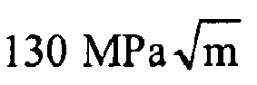
- the gear includes an iron alloy having a strength of approximately 1150 MPa or greater and a shear fracture toughness of 100 MPa m or greater. In one example, the iron alloy has a strength of greater than 1900 MPa and a shear fracture toughness of greater than 130 MPa m .
- the gears have teeth with a case hardness of approximately 44 HRC or greater in one example. The teeth have a surface finish of less than 16 ⁇ /in. (16 ⁇ m/25.4mm), for example.
- FIG. 1 An engine 10 with geared architecture is shown in Figure 1 .
- a pylon typically secures the engine 10 to an aircraft.
- the engine 10 includes a core nacelle 12 that surrounds a low spool 14 and high spool 24 that are rotatable about a common axis A1.
- the low spool 14 supports a low pressure compressor 16 and low pressure turbine 18.
- the low spool 14 drives a fan 20 through a gear train 22.
- the high spool 24 supports a high pressure compressor 26 and high pressure turbine 28.
- a combustor (not shown) is arranged between the high pressure compressor 26 and high pressure turbine 28. Compressed air from compressors 16, 26 mixes with fuel from the combustor 30 and is expanded in turbines 18, 28.
- the engine 10 is a high bypass turbofan arrangement.
- the bypass ratio is greater than 10
- the turbofan diameter is substantially larger than the diameter of the low pressure compressor 16.
- the low pressure turbine 18 has a pressure ratio that is greater than 5:1, in one example.
- the gear train 22 is an epicycle gear train, for example, a star gear train, providing a gear reduction ratio of greater than 2.5:1, for example. It should be understood, however, that the above parameters are only exemplary of a contemplated geared architecture engine. That is, the invention is applicable to other engines including direct drive turbofans.
- the fan 20 directs air into the core nacelle 12, which is used to drive the turbines 18, 28, as is known in the art.
- Turbine exhaust exits the core nacelle 12 once it has been expanded in the turbines 18, 28, in a passage provided between the core nacelle 12 and a tail cone 32.
- a core housing 11 is arranged within the core nacelle 12 and is supported within the fan nacelle 34 by structure 36, such as flow exit guide vanes.
- a generally annular bypass flow path 38 is arranged between the core and fan nacelles 12, 34.
- the examples illustrated in the Figures depict a high bypass flow arrangement in which approximately eighty percent of the airflow entering the fan nacelle 34 bypasses the core nacelle 12.
- the bypass flow within the bypass flow path 38 exits the fan nacelle 34 through a fan nozzle exit area at the aft of the fan nacelle 34.
- accessory drive gearboxes 40, 140 used to drive accessory components are schematically illustrated at different location within the engine. Unlike a helicopter gearbox, an aircraft gearbox is subject to temperatures above 300°F (150°C), which has a significant negative impact on gear life. Large gears have been used to survive in these temperatures.
- one accessory drive gearbox 40 is arranged in a radial space between the fan case 35 and an exterior surface 33 of the fan nacelle 34.
- An accessory drive component 41 is shown schematically mounted on the gearbox 40.
- an accessory drive gearbox 140 is arranged in a radial space between the core housing 11 and an exterior surface 13 of the core nacelle 12. Accessory drive gearboxes 40, 140 can be housed within either nacelle or both, if desired.
- a prior art gearbox 40 is shown in Figures 2a and 2b .
- the gearbox 40 includes mounts 39 for securing the gearbox 40 to the engine 10.
- Example accessory drive components are: a fuel pump, hydraulic pump, generator and lubrication pump.
- the mounting pads for the accessory drive components indicated above are respectively provided at 42, 44, 46, 48.
- An input shaft mounting pad is illustrated at 51.
- the gearbox 40 includes first and second gears 54, 56 that are schematically shown in Figure 3 .
- the gears have an axis A2 that is parallel with the axis A1.
- the first and second gears 54, 56 include teeth 58 having surfaces 60.
- the first and second gears 54, 56 transmit rotational drive from a spool to an accessory drive component.
- the size of the gearbox 40 also increases thus increasing the circumference of the nacelle that houses the gearbox.
- first a suitable alloy is selected having a desired toughness.
- the alloy is case-hardened.
- the case-hardened alloy is superfinished.
- an iron alloy is used to form the gears. It is desirable to provide a high strength, high toughness material, which enables to the size of the gear to be reduced.
- Example iron alloys with high strength and toughness contain nickel, cobalt, chromium, molybdenum, and carbon.
- One example iron alloy has a strength of approximately 1150 MPa or greater and a shear fracture toughness of approximately 100 MPa m or greater.
- the iron alloy has a strength of approximately 1900 MPa or greater and a shear fracture toughness of approximately 130 MPa m or greater.
- the gears are manufactured from AerMet 100 or AerMet 310, available from Carpenter Technologies.
- the gears are manufactured from Ferrium C69, available from Questek. Pyrowear 53 is another example iron alloy. The above-listed alloys are exemplary only.
- iron alloys can be selected according to U.S. Application Nos. 10/937,004 and 10/937,100 , which are incorporated by reference.
- the iron alloys avoid disadvantages associated with typical gear alloys that have a low softening point and must be case-hardened at temperatures much greater than their tempering point. This results in distortion, which requires significant final machining. It is desirable to avoid machining after case-hardening in which material must be removed from the gear teeth to achieve desired dimensions.
- the size of the gears can also be reduced by increasing the case hardness of the gear.
- High strength and toughness alloys such as AerMet 100, cannot withstand airplane gearbox conditions.
- the gears 54, 56 can be carburized or nitrided to increase the hardness of the surface 60 to approximately 44 HRC or greater.
- the core hardness of the gears is approximately 52 HRC and the surface hardness is approximately 60-62 HRC after carburizing. Ion nitriding the surface 60 can result in a hardness of greater than 65 HRC in one example.
- Alloy selection and hardening can eliminate post-process machining thereby greatly reducing manufacturing costs.
- desired case hardening can be achieved.
- one desired surface treatment uses a high current density ion implantation that results in a case depth of 12 microns without distorting the part or producing a surface white layer that must be removed by subsequent machining.
- the ground surface finish of an airplane gearbox gear is 16 ⁇ /in.
- Isotropic superfinishing can be employed to improve the surface characteristics of the gears 54, 56 thereby further enabling the size of the gears to be reduced.
- isotropic superfinishing processes can be employed.
- the gear can be agitated in a vibrating finisher using an aqueous mixture of sodium bisulfate, monosodium phosphate, potassium dichromate and potassium phosphate to obtain an isotropic superfinish.
- oxalic acid, sodium nitrate and hydrogen peroxide can be used in the vibratory finisher. Bending, pitting and scoring of the gear teeth thereby can be reduced.
- Isotropic superfinishing can achieve a finish of 3 ⁇ /in. (3 ⁇ m/25.4mm).
- the power density of the gears can be increased by 53% in one example.
Landscapes
- Engineering & Computer Science (AREA)
- Chemical & Material Sciences (AREA)
- Mechanical Engineering (AREA)
- General Engineering & Computer Science (AREA)
- Thermal Sciences (AREA)
- Physics & Mathematics (AREA)
- Combustion & Propulsion (AREA)
- Crystallography & Structural Chemistry (AREA)
- Materials Engineering (AREA)
- Metallurgy (AREA)
- Organic Chemistry (AREA)
- Electromagnetism (AREA)
- Gears, Cams (AREA)
- Retarders (AREA)
Abstract
Description
- This disclosure generally relates to a gas turbine engine. More particularly, the disclosure relates to gears for a gearbox, which has a nacelle arranged about the gearbox.
- Gas turbine engines for commercial aircraft applications typically include an engine core housed within a core nacelle. In one type of arrangement known as a turbofan engine, the core drives a large fan upstream from the core that provides airflow into the core. One or more spools are arranged within the core, and a gear train may be provided between one of the spools and the fan. A fan case and nacelle surround the fan and at least a portion of the core.
- An inlet of the fan nacelle is designed to avoid flow separation. At cruise conditions, a thinner inlet lip is desired to minimize drag and increase fuel economy. The nacelles are sized to accommodate the widest section of engine, which is often dictated by the size of an accessory drive gearbox. The accessory drive gearbox, which is driven by a spool through a radial tower shaft and angle gearbox, is typically contained within either the fan nacelle or the core nacelle. The gearbox is sized to accommodate gears used to drive the accessory components. The gears must be durable enough to withstand the power transmitted through them without excessive bending, galling or pitting.
- Typically, carburized steel gears are used in gearboxes. Helicopter gearboxes are subject to stringent noise, weight and vibration limitations. To address these limitations, the gears have been nitrided, thus enabling smaller gears to be used thereby reducing the weight of the gearbox. Helicopter gearbox gears separately have been superfinished to reduce bending and pitting. However, gearbox noise and weight and other helicopter gear issues traditionally have not been issues for airplane gas turbine engine applications.
- What is needed is a gas turbine engine design with a reduced diameter nacelle, which houses a smaller accessory drive gearbox.
- A gas turbine engine is provided that includes a spool that supports a turbine. A gearbox is operatively coupled to the spool through a transmission device configured to transfer rotational drive from the spool to the gearbox. An accessory drive component is coupled to the gearbox. The gearbox is arranged radially between the gas turbine engine and a nacelle that is arranged about the gas turbine engine.
- A gear is supported by the gearbox and configured to transmit the rotational drive to the accessory drive component. The gear includes an iron alloy having a strength of approximately 1150 MPa or greater and a shear fracture toughness of 100 MPa


- These and other features of the disclosure can be best understood from the following specification and drawings, the following of which is a brief description.
-
Figure 1 is a highly schematic view of a turbofan gas turbine engine. -
Figure 2a is a front perspective view of an accessory drive gearbox. -
Figure 2b is a rear perspective view of the accessory drive gearbox shown inFigure 2a . -
Figure 3 is a schematic view of gas turbine accessory drive gearbox gears according to one example of this disclosure. - An
engine 10 with geared architecture is shown inFigure 1 . A pylon typically secures theengine 10 to an aircraft. Theengine 10 includes acore nacelle 12 that surrounds alow spool 14 andhigh spool 24 that are rotatable about a common axis A1. Thelow spool 14 supports alow pressure compressor 16 andlow pressure turbine 18. In the example, thelow spool 14 drives afan 20 through agear train 22. Thehigh spool 24 supports ahigh pressure compressor 26 andhigh pressure turbine 28. A combustor (not shown) is arranged between thehigh pressure compressor 26 andhigh pressure turbine 28. Compressed air fromcompressors turbines - In the example shown, the
engine 10 is a high bypass turbofan arrangement. In one example, the bypass ratio is greater than 10, and the turbofan diameter is substantially larger than the diameter of thelow pressure compressor 16. Thelow pressure turbine 18 has a pressure ratio that is greater than 5:1, in one example. Thegear train 22 is an epicycle gear train, for example, a star gear train, providing a gear reduction ratio of greater than 2.5:1, for example. It should be understood, however, that the above parameters are only exemplary of a contemplated geared architecture engine. That is, the invention is applicable to other engines including direct drive turbofans. - Airflow enters a
fan nacelle 34, which surrounds thecore nacelle 12 andfan 20. Thefan 20 directs air into thecore nacelle 12, which is used to drive theturbines core nacelle 12 once it has been expanded in theturbines core nacelle 12 and atail cone 32. - A
core housing 11 is arranged within thecore nacelle 12 and is supported within thefan nacelle 34 bystructure 36, such as flow exit guide vanes. A generally annularbypass flow path 38 is arranged between the core andfan nacelles fan nacelle 34 bypasses thecore nacelle 12. The bypass flow within thebypass flow path 38 exits thefan nacelle 34 through a fan nozzle exit area at the aft of thefan nacelle 34. - In the example shown in
Figure 1 ,accessory drive gearboxes accessory drive gearbox 40 is arranged in a radial space between thefan case 35 and anexterior surface 33 of thefan nacelle 34. Anaccessory drive component 41 is shown schematically mounted on thegearbox 40. Alternatively, anaccessory drive gearbox 140 is arranged in a radial space between thecore housing 11 and anexterior surface 13 of thecore nacelle 12.Accessory drive gearboxes - A
prior art gearbox 40 is shown inFigures 2a and 2b . Thegearbox 40 includesmounts 39 for securing thegearbox 40 to theengine 10. Example accessory drive components are: a fuel pump, hydraulic pump, generator and lubrication pump. The mounting pads for the accessory drive components indicated above are respectively provided at 42, 44, 46, 48. An input shaft mounting pad is illustrated at 51. - The
gearbox 40 includes first andsecond gears Figure 3 . The gears have an axis A2 that is parallel with the axis A1. The first andsecond gears teeth 58 havingsurfaces 60. The first andsecond gears second gears gearbox 40 increases, the size of thegearbox 40 also increases thus increasing the circumference of the nacelle that houses the gearbox. To this end, it is desirable to reduce the size of the gearbox gears, thereby decreasing the size of the nacelle that is needed to accommodate the gearbox. In one disclosed embodiment, first a suitable alloy is selected having a desired toughness. Secondly, the alloy is case-hardened. Thirdly, the case-hardened alloy is superfinished. - In one example, an iron alloy is used to form the gears. It is desirable to provide a high strength, high toughness material, which enables to the size of the gear to be reduced. Example iron alloys with high strength and toughness contain nickel, cobalt, chromium, molybdenum, and carbon. One example iron alloy has a strength of approximately 1150 MPa or greater and a shear fracture toughness of approximately 100 MPa


- Other suitable iron alloys can be selected according to
U.S. Application Nos. 10/937,004 and10/937,100 - The size of the gears can also be reduced by increasing the case hardness of the gear. High strength and toughness alloys, such as AerMet 100, cannot withstand airplane gearbox conditions. Accordingly, the
gears surface 60 to approximately 44 HRC or greater. In one example, the core hardness of the gears is approximately 52 HRC and the surface hardness is approximately 60-62 HRC after carburizing. Ion nitriding thesurface 60 can result in a hardness of greater than 65 HRC in one example. - Alloy selection and hardening, such as nitriding, can eliminate post-process machining thereby greatly reducing manufacturing costs. By employing plasma/ion nitriding according to exemplary methods disclosed in
U.S. Application Nos. 10/937,004 ;10/870,489 10/937,100 - Typically, the ground surface finish of an airplane gearbox gear is 16µ/in. Isotropic superfinishing can be employed to improve the surface characteristics of the
gears - By using a suitable iron alloy, such as Aermet 100 (which has also been case-hardened), and employing isotropic superfinishing, the power density of the gears can be increased by 53% in one example.
- Although an example embodiment has been disclosed, a worker of ordinary skill in this art would recognize that certain modifications would come within the scope of the claims. For that reason, the following claims should be studied to determine their true scope and content.
Claims (15)
- A method of manufacturing a gas turbine engine comprising the steps of:providing an iron alloy gear;case- hardening teeth on the gear;isotropicly superfinishing the teeth;installing the superfinished, case-hardened alloy gear into a gearbox; andmounting the gearbox to a gas turbine engine.
- The method according to claim 1, wherein the iron alloy gear includes nickel, cobalt, chromium, molybdenum and carbon.
- The method according to claim 1 or 2, wherein the case-hardening step includes plasma nitriding the gear, the superfinishing step provides a surface finish of less than 16 µ/in. (16 µm/25.4mm), and the superfinishing step is performed after the case-hardening step without dimensionally machining the teeth.
- The method according to any preceding claim, wherein the iron alloy includes a shear fracture toughness of approximately greater than 100 MPa

- The method according to claim 4, wherein the iron alloy includes a shear fracture toughness of approximately 130 MPa

- The method according to any preceding claim, comprising the step of installing a nacelle about the gas turbine engine with the gearbox arranged radially between the gas turbine engine and the nacelle, the gear and gas turbine engine having parallel axes.
- A gas turbine engine gearbox gear comprising:a gear including an iron alloy having a strength of approximately 1150 MPa or greater and a shear fracture toughness of approximately 100 MPa

- The gas turbine engine gearbox gear according to claim 7, wherein the iron alloy gear includes nickel, cobalt, chromium, molybdenum and carbon.
- The gas turbine engine gearbox gear according to claim 7 or 8, wherein the case hardness extends a depth of 12 microns from a surface of the gear.
- The gas turbine engine gearbox gear according to any of claims 7 to 9, wherein the case hardness is greater than 60 HRC.
- The gas turbine engine gearbox gear according to claim 10, wherein the case hardness is greater than 65 HRC.
- The gas turbine engine gearbox gear according to any of claims 7 to 11, wherein the surface finish is approximately 3µ/in. (3µm/25.4mm).
- The gas turbine engine gearbox gear according to any of claims 7 to 12, wherein the shear fracture toughness is greater than approximately 130 MPa

- The gas turbine engine gearbox gear according to any of claims 7 to 13, wherein the strength is greater than approximately 1900 MPa.
- A gas turbine engine comprising:a spool that supports a turbine;a gearbox operatively coupled to the spool through a transmission device configured to transfer rotational drive from the spool to the gearbox,an accessory drive component coupled to the gearbox; anda gas turbine engine gearbox gear supported by the gearbox and configured to transmit rotational drive to the accessory drive component as claimed in any of claims 7 to 14.
Applications Claiming Priority (1)
| Application Number | Priority Date | Filing Date | Title |
|---|---|---|---|
| US12/041,732 US20090223052A1 (en) | 2008-03-04 | 2008-03-04 | Gearbox gear and nacelle arrangement |
Publications (3)
| Publication Number | Publication Date |
|---|---|
| EP2098757A2 true EP2098757A2 (en) | 2009-09-09 |
| EP2098757A3 EP2098757A3 (en) | 2011-06-01 |
| EP2098757B1 EP2098757B1 (en) | 2014-04-23 |
Family
ID=40689005
Family Applications (1)
| Application Number | Title | Priority Date | Filing Date |
|---|---|---|---|
| EP09250627.8A Active EP2098757B1 (en) | 2008-03-04 | 2009-03-04 | Gearbox gear and nacelle arrangement |
Country Status (2)
| Country | Link |
|---|---|
| US (1) | US20090223052A1 (en) |
| EP (1) | EP2098757B1 (en) |
Cited By (6)
| Publication number | Priority date | Publication date | Assignee | Title |
|---|---|---|---|---|
| EP2395202A3 (en) * | 2010-06-08 | 2013-07-17 | Rolls-Royce plc | A mounting assembly for a gearbox of gas turbine engine |
| WO2014051662A1 (en) * | 2012-09-28 | 2014-04-03 | United Technologies Corporation | Gas turbine engine having support structure with swept leading edge |
| EP2898205A4 (en) * | 2012-09-20 | 2015-10-28 | United Technologies Corp | AUXILIARY GEARBOX FOR GAS TURBINE MOTOR |
| EP3502302A1 (en) * | 2017-12-22 | 2019-06-26 | Ge Avio S.r.l. | Nitriding process for carburizing ferrium steels |
| WO2021116570A1 (en) * | 2019-12-13 | 2021-06-17 | Safran Aircraft Engines | Hydraulic equipment plate for aeronautical turbomachine |
| WO2022157545A1 (en) * | 2021-01-22 | 2022-07-28 | Caterpillar Inc. | Tooth geometry for headstock gear for feed system of a shearer loader |
Families Citing this family (13)
| Publication number | Priority date | Publication date | Assignee | Title |
|---|---|---|---|---|
| US9121351B2 (en) * | 2008-10-30 | 2015-09-01 | Rolls-Royce North American Technologies, Inc. | Gas turbine engine accessory system |
| US9145834B2 (en) | 2011-06-14 | 2015-09-29 | Honeywell International Inc. | Transverse mounted accessory gearbox |
| US9926849B2 (en) | 2011-06-14 | 2018-03-27 | Honeywell International Inc. | Transverse mounted accessory gearbox |
| DE102011112253A1 (en) * | 2011-09-02 | 2013-03-07 | Rolls-Royce Deutschland Ltd & Co Kg | Assembly for an engine of an aircraft |
| US8973465B2 (en) | 2012-07-20 | 2015-03-10 | United Technologies Corporation | Gearbox for gas turbine engine |
| EP2904250A4 (en) | 2012-10-01 | 2015-10-21 | United Technologies Corp | TRANSMISSION TOLERANCES WITH HIGH GEAR POWER DENSITY |
| EP3741961B1 (en) | 2013-01-30 | 2024-05-01 | RTX Corporation | Gas turbine engine accessory gearbox |
| PL3012349T3 (en) | 2014-10-22 | 2020-02-28 | Rem Technologies, Inc. | Method for inspecting and processing high hardness alloy steels |
| EP3277857B1 (en) | 2015-04-02 | 2021-05-05 | Sikorsky Aircraft Corporation | Carburization of steel components |
| US11293351B2 (en) | 2020-07-16 | 2022-04-05 | Raytheon Technologies Corporation | Gas turbine engine including seal assembly with abradable coating including magnetic particles embedded in polymer |
| US11313281B2 (en) * | 2020-07-16 | 2022-04-26 | Raytheon Technologies Corporation | Gas turbine engine including seal assembly with abradable coating including magnetic particles |
| US11313280B2 (en) | 2020-07-16 | 2022-04-26 | Raytheon Technologies Corporation | Gas turbine engine including seal assembly with abradable coating and cutter |
| DE102020122734A1 (en) | 2020-08-31 | 2022-03-03 | Rolls-Royce Deutschland Ltd & Co Kg | Heat treatment process for secondary hardening steels |
Family Cites Families (25)
| Publication number | Priority date | Publication date | Assignee | Title |
|---|---|---|---|---|
| US4491500A (en) * | 1984-02-17 | 1985-01-01 | Rem Chemicals, Inc. | Method for refinement of metal surfaces |
| US4832909A (en) * | 1986-12-22 | 1989-05-23 | Carpenter Technology Corporation | Low cobalt-containing maraging steel with improved toughness |
| US5087415A (en) * | 1989-03-27 | 1992-02-11 | Carpenter Technology Corporation | High strength, high fracture toughness structural alloy |
| US5268044A (en) * | 1990-02-06 | 1993-12-07 | Carpenter Technology Corporation | High strength, high fracture toughness alloy |
| JP3308377B2 (en) * | 1994-03-09 | 2002-07-29 | 大同特殊鋼株式会社 | Gear with excellent tooth surface strength and method of manufacturing the same |
| US5549764A (en) * | 1995-04-21 | 1996-08-27 | Caterpillar Inc. | Wear resistant coated steel article |
| US5866066A (en) * | 1996-09-09 | 1999-02-02 | Crs Holdings, Inc. | Age hardenable alloy with a unique combination of very high strength and good toughness |
| US6918502B1 (en) * | 1997-12-19 | 2005-07-19 | Rehrig Pacific Company | Collapsible container |
| US6302356B1 (en) * | 1998-08-21 | 2001-10-16 | Rolls-Royce Corporation | Helicopter two stage main reduction gearbox |
| US6732606B1 (en) * | 2000-06-30 | 2004-05-11 | Eaton Corporation | Polished gear surfaces |
| US20020088773A1 (en) * | 2001-01-10 | 2002-07-11 | Holland Jerry Dwayne | Nonabrasive media with accelerated chemistry |
| EP1255059A3 (en) * | 2001-04-26 | 2009-04-15 | Fuji Jukogyo Kabushiki Kaisha | Center differential unit and planetary gear |
| JP4718781B2 (en) * | 2003-02-28 | 2011-07-06 | Ntn株式会社 | Transmission components and tapered roller bearings |
| JP4570066B2 (en) * | 2003-07-22 | 2010-10-27 | 日産自動車株式会社 | Method for manufacturing sintered sprocket for silent chain |
| KR101507261B1 (en) * | 2003-09-02 | 2015-03-30 | 나미키 세이미쓰 하우세키 가부시키가이샤 | Precision gear, its gear mechanism and production method of precision gear |
| US7169238B2 (en) * | 2003-12-22 | 2007-01-30 | Caterpillar Inc | Carbide method and article for hard finishing resulting in improved wear resistance |
| US7208052B2 (en) * | 2003-12-23 | 2007-04-24 | Rolls-Royce Corporation | Method for carburizing steel components |
| US20050193852A1 (en) * | 2004-03-05 | 2005-09-08 | Cooper Clark V. | Transmission system with increased power density |
| US7186304B2 (en) * | 2004-06-02 | 2007-03-06 | United Technologies Corporation | Carbo-nitrided case hardened martensitic stainless steels |
| US7556699B2 (en) * | 2004-06-17 | 2009-07-07 | Cooper Clark Vantine | Method of plasma nitriding of metals via nitrogen charging |
| US20060048857A1 (en) * | 2004-09-09 | 2006-03-09 | Cooper Clark V | Method for processing alloys via high-current density ion implantation |
| US7695573B2 (en) * | 2004-09-09 | 2010-04-13 | Sikorsky Aircraft Corporation | Method for processing alloys via plasma (ion) nitriding |
| CN101184868A (en) * | 2005-04-06 | 2008-05-21 | 雷姆技术公司 | Super Polishing of High Density Carbide |
| US7500365B2 (en) * | 2005-05-05 | 2009-03-10 | United Technologies Corporation | Accessory gearbox |
| US8758527B2 (en) * | 2006-12-15 | 2014-06-24 | Sikorsky Aircraft Corporation | Gear material for an enhanced rotorcraft drive system |
-
2008
- 2008-03-04 US US12/041,732 patent/US20090223052A1/en not_active Abandoned
-
2009
- 2009-03-04 EP EP09250627.8A patent/EP2098757B1/en active Active
Cited By (16)
| Publication number | Priority date | Publication date | Assignee | Title |
|---|---|---|---|---|
| US8943840B2 (en) | 2010-06-08 | 2015-02-03 | Rolls-Royce Plc | Mounting assembly |
| EP2395202A3 (en) * | 2010-06-08 | 2013-07-17 | Rolls-Royce plc | A mounting assembly for a gearbox of gas turbine engine |
| EP2898205A4 (en) * | 2012-09-20 | 2015-10-28 | United Technologies Corp | AUXILIARY GEARBOX FOR GAS TURBINE MOTOR |
| US10184404B2 (en) | 2012-09-20 | 2019-01-22 | United Technologies Corporation | Geared gas turbine engine accessory gearbox |
| WO2014051662A1 (en) * | 2012-09-28 | 2014-04-03 | United Technologies Corporation | Gas turbine engine having support structure with swept leading edge |
| US10808621B2 (en) | 2012-09-28 | 2020-10-20 | Raytheon Technologies Corporation | Gas turbine engine having support structure with swept leading edge |
| US11162167B2 (en) | 2017-12-22 | 2021-11-02 | Ge Avio S.R.L | Nitriding process for carburizing Ferrium steels |
| EP3502302A1 (en) * | 2017-12-22 | 2019-06-26 | Ge Avio S.r.l. | Nitriding process for carburizing ferrium steels |
| CN109972077A (en) * | 2017-12-22 | 2019-07-05 | 通用电气阿维奥有限责任公司 | Nitriding process for carburizing Ferrium steel |
| US11840765B2 (en) | 2017-12-22 | 2023-12-12 | Ge Avio S.R.L. | Nitriding process for carburizing ferrium steels |
| CN109972077B (en) * | 2017-12-22 | 2021-10-29 | 通用电气阿维奥有限责任公司 | Nitriding process for carburizing Ferrium steel |
| WO2021116570A1 (en) * | 2019-12-13 | 2021-06-17 | Safran Aircraft Engines | Hydraulic equipment plate for aeronautical turbomachine |
| FR3104640A1 (en) * | 2019-12-13 | 2021-06-18 | Safran Aircraft Engines | Aircraft turbomachine hydraulic equipment plate |
| US12163475B2 (en) | 2019-12-13 | 2024-12-10 | Safran Aircraft Engines | Hydraulic equipment plate for aeronautical turbomachine |
| WO2022157545A1 (en) * | 2021-01-22 | 2022-07-28 | Caterpillar Inc. | Tooth geometry for headstock gear for feed system of a shearer loader |
| US12504063B2 (en) | 2021-01-22 | 2025-12-23 | Caterpillar Inc. | Tooth geometry for headstock gear for feed system of a shearer loader |
Also Published As
| Publication number | Publication date |
|---|---|
| EP2098757B1 (en) | 2014-04-23 |
| EP2098757A3 (en) | 2011-06-01 |
| US20090223052A1 (en) | 2009-09-10 |
Similar Documents
| Publication | Publication Date | Title |
|---|---|---|
| EP2098757B1 (en) | Gearbox gear and nacelle arrangement | |
| EP1429005B1 (en) | Coated journals of a geartrain in a turbofan engine | |
| EP1435475B1 (en) | Planet gear journal for an epicyclic gear system | |
| EP3258084B1 (en) | An accessory gearbox assembly and a gas turbine engine comprising an accessory gearbox assembly | |
| EP3029358B1 (en) | Lightweight and compliant journal pin | |
| US10247298B2 (en) | Resilient bearing pin and gear assemblies including resilient bearing pins | |
| EP2388439B1 (en) | Airfoil component having electrochemically insulating layer | |
| US8074455B2 (en) | Gas turbine engine with a means of driving the accessory gear box, and method of fitting said engine | |
| US10228024B2 (en) | Reduced-weight bearing pins and methods of manufacturing such bearing pins | |
| EP2855880B1 (en) | Front bearing support for a fan drive gear system | |
| US20190186598A1 (en) | Apparatus and system for thin rim planet gear for aircraft engine power gearbox | |
| CN110234858B (en) | Lock Nut Sun Gears for Gas Turbine Engines | |
| US20200157971A1 (en) | Structural assembly for a gas turbine engine | |
| US20230193945A1 (en) | Bolt assembly | |
| EP2906798A1 (en) | Bearing support stiffness control | |
| DE102010014968A1 (en) | Multi-shaft engine with tandem generator | |
| US9121296B2 (en) | Rotatable component with controlled load interface | |
| US10408134B2 (en) | Gears, gear arrangements and gas turbine engines | |
| EP3964695B1 (en) | Air turbine starter | |
| EP2472064A2 (en) | Airfoil for gas turbine engine | |
| CN112610337B (en) | Reinforcement member for epicyclic gear system housing assembly | |
| EP3926213B1 (en) | Epicyclic gearing with press-fit collar with reduced edge contact stress concentrations | |
| CN114776395A (en) | Efficient epicyclic gear assembly for a turbomachine and method of manufacturing the same | |
| US20200282448A1 (en) | Manufacturing method | |
| CN112610659B (en) | Epicyclic Gear System Housing Assemblies |
Legal Events
| Date | Code | Title | Description |
|---|---|---|---|
| PUAI | Public reference made under article 153(3) epc to a published international application that has entered the european phase |
Free format text: ORIGINAL CODE: 0009012 |
|
| AK | Designated contracting states |
Kind code of ref document: A2 Designated state(s): AT BE BG CH CY CZ DE DK EE ES FI FR GB GR HR HU IE IS IT LI LT LU LV MC MK MT NL NO PL PT RO SE SI SK TR |
|
| AX | Request for extension of the european patent |
Extension state: AL BA RS |
|
| PUAL | Search report despatched |
Free format text: ORIGINAL CODE: 0009013 |
|
| RIC1 | Information provided on ipc code assigned before grant |
Ipc: B24B 31/06 20060101ALI20110421BHEP Ipc: F16H 55/06 20060101AFI20090610BHEP |
|
| AK | Designated contracting states |
Kind code of ref document: A3 Designated state(s): AT BE BG CH CY CZ DE DK EE ES FI FR GB GR HR HU IE IS IT LI LT LU LV MC MK MT NL NO PL PT RO SE SI SK TR |
|
| AX | Request for extension of the european patent |
Extension state: AL BA RS |
|
| 17P | Request for examination filed |
Effective date: 20111129 |
|
| AKX | Designation fees paid |
Designated state(s): DE GB |
|
| 17Q | First examination report despatched |
Effective date: 20120214 |
|
| REG | Reference to a national code |
Ref country code: DE Ref legal event code: R079 Ref document number: 602009023435 Country of ref document: DE Free format text: PREVIOUS MAIN CLASS: F16H0055060000 Ipc: C21D0009320000 |
|
| RIC1 | Information provided on ipc code assigned before grant |
Ipc: B24B 1/04 20060101ALI20130318BHEP Ipc: F16H 55/06 20060101ALI20130318BHEP Ipc: F02C 7/32 20060101ALI20130318BHEP Ipc: B24B 31/06 20060101ALI20130318BHEP Ipc: C21D 9/32 20060101AFI20130318BHEP |
|
| GRAP | Despatch of communication of intention to grant a patent |
Free format text: ORIGINAL CODE: EPIDOSNIGR1 |
|
| INTG | Intention to grant announced |
Effective date: 20140113 |
|
| GRAS | Grant fee paid |
Free format text: ORIGINAL CODE: EPIDOSNIGR3 |
|
| GRAA | (expected) grant |
Free format text: ORIGINAL CODE: 0009210 |
|
| AK | Designated contracting states |
Kind code of ref document: B1 Designated state(s): DE GB |
|
| REG | Reference to a national code |
Ref country code: GB Ref legal event code: FG4D |
|
| REG | Reference to a national code |
Ref country code: DE Ref legal event code: R096 Ref document number: 602009023435 Country of ref document: DE Effective date: 20140605 |
|
| REG | Reference to a national code |
Ref country code: DE Ref legal event code: R097 Ref document number: 602009023435 Country of ref document: DE |
|
| PLBE | No opposition filed within time limit |
Free format text: ORIGINAL CODE: 0009261 |
|
| STAA | Information on the status of an ep patent application or granted ep patent |
Free format text: STATUS: NO OPPOSITION FILED WITHIN TIME LIMIT |
|
| 26N | No opposition filed |
Effective date: 20150126 |
|
| REG | Reference to a national code |
Ref country code: DE Ref legal event code: R097 Ref document number: 602009023435 Country of ref document: DE Effective date: 20150126 |
|
| REG | Reference to a national code |
Ref country code: DE Ref legal event code: R082 Ref document number: 602009023435 Country of ref document: DE Representative=s name: SCHMITT-NILSON SCHRAUD WAIBEL WOHLFROM PATENTA, DE |
|
| REG | Reference to a national code |
Ref country code: DE Ref legal event code: R082 Ref document number: 602009023435 Country of ref document: DE Representative=s name: SCHMITT-NILSON SCHRAUD WAIBEL WOHLFROM PATENTA, DE Ref country code: DE Ref legal event code: R081 Ref document number: 602009023435 Country of ref document: DE Owner name: UNITED TECHNOLOGIES CORP. (N.D.GES.D. STAATES , US Free format text: FORMER OWNER: UNITED TECHNOLOGIES CORP., HARTFORD, CONN., US |
|
| REG | Reference to a national code |
Ref country code: DE Ref legal event code: R081 Ref document number: 602009023435 Country of ref document: DE Owner name: RAYTHEON TECHNOLOGIES CORPORATION (N.D.GES.D.S, US Free format text: FORMER OWNER: UNITED TECHNOLOGIES CORP. (N.D.GES.D. STAATES DELAWARE), FARMINGTON, CONN., US Ref country code: DE Ref legal event code: R081 Ref document number: 602009023435 Country of ref document: DE Owner name: RTX CORPORATION (N.D.GES.D. STAATES DELAWARE),, US Free format text: FORMER OWNER: UNITED TECHNOLOGIES CORP. (N.D.GES.D. STAATES DELAWARE), FARMINGTON, CONN., US |
|
| P01 | Opt-out of the competence of the unified patent court (upc) registered |
Effective date: 20230519 |
|
| REG | Reference to a national code |
Ref country code: DE Ref legal event code: R081 Ref document number: 602009023435 Country of ref document: DE Owner name: RTX CORPORATION (N.D.GES.D. STAATES DELAWARE),, US Free format text: FORMER OWNER: RAYTHEON TECHNOLOGIES CORPORATION (N.D.GES.D.STAATES DELAWARE), ARLINGTON, VA, US |
|
| PGFP | Annual fee paid to national office [announced via postgrant information from national office to epo] |
Ref country code: GB Payment date: 20260220 Year of fee payment: 18 |
|
| PGFP | Annual fee paid to national office [announced via postgrant information from national office to epo] |
Ref country code: DE Payment date: 20260219 Year of fee payment: 18 |