EP4072931B1 - Motorised scooter - Google Patents
Motorised scooter Download PDFInfo
- Publication number
- EP4072931B1 EP4072931B1 EP20828821.7A EP20828821A EP4072931B1 EP 4072931 B1 EP4072931 B1 EP 4072931B1 EP 20828821 A EP20828821 A EP 20828821A EP 4072931 B1 EP4072931 B1 EP 4072931B1
- Authority
- EP
- European Patent Office
- Prior art keywords
- steering
- deck
- scooter
- tiller
- rotation
- Prior art date
- Legal status (The legal status is an assumption and is not a legal conclusion. Google has not performed a legal analysis and makes no representation as to the accuracy of the status listed.)
- Active
Links
Images














Classifications
-
- B—PERFORMING OPERATIONS; TRANSPORTING
- B62—LAND VEHICLES FOR TRAVELLING OTHERWISE THAN ON RAILS
- B62J—CYCLE SADDLES OR SEATS; AUXILIARY DEVICES OR ACCESSORIES SPECIALLY ADAPTED TO CYCLES AND NOT OTHERWISE PROVIDED FOR, e.g. ARTICLE CARRIERS OR CYCLE PROTECTORS
- B62J25/00—Foot-rests; Knee grips; Passenger hand-grips
- B62J25/04—Floor-type foot rests
-
- B—PERFORMING OPERATIONS; TRANSPORTING
- B62—LAND VEHICLES FOR TRAVELLING OTHERWISE THAN ON RAILS
- B62J—CYCLE SADDLES OR SEATS; AUXILIARY DEVICES OR ACCESSORIES SPECIALLY ADAPTED TO CYCLES AND NOT OTHERWISE PROVIDED FOR, e.g. ARTICLE CARRIERS OR CYCLE PROTECTORS
- B62J43/00—Arrangements of batteries
-
- B—PERFORMING OPERATIONS; TRANSPORTING
- B62—LAND VEHICLES FOR TRAVELLING OTHERWISE THAN ON RAILS
- B62K—CYCLES; CYCLE FRAMES; CYCLE STEERING DEVICES; RIDER-OPERATED TERMINAL CONTROLS SPECIALLY ADAPTED FOR CYCLES; CYCLE AXLE SUSPENSIONS; CYCLE SIDECARS, FORECARS, OR THE LIKE
- B62K15/00—Collapsible or foldable cycles
- B62K15/006—Collapsible or foldable cycles the frame being foldable
-
- B—PERFORMING OPERATIONS; TRANSPORTING
- B62—LAND VEHICLES FOR TRAVELLING OTHERWISE THAN ON RAILS
- B62K—CYCLES; CYCLE FRAMES; CYCLE STEERING DEVICES; RIDER-OPERATED TERMINAL CONTROLS SPECIALLY ADAPTED FOR CYCLES; CYCLE AXLE SUSPENSIONS; CYCLE SIDECARS, FORECARS, OR THE LIKE
- B62K21/00—Steering devices
-
- B—PERFORMING OPERATIONS; TRANSPORTING
- B62—LAND VEHICLES FOR TRAVELLING OTHERWISE THAN ON RAILS
- B62K—CYCLES; CYCLE FRAMES; CYCLE STEERING DEVICES; RIDER-OPERATED TERMINAL CONTROLS SPECIALLY ADAPTED FOR CYCLES; CYCLE AXLE SUSPENSIONS; CYCLE SIDECARS, FORECARS, OR THE LIKE
- B62K21/00—Steering devices
- B62K21/12—Handlebars; Handlebar stems
-
- B—PERFORMING OPERATIONS; TRANSPORTING
- B62—LAND VEHICLES FOR TRAVELLING OTHERWISE THAN ON RAILS
- B62K—CYCLES; CYCLE FRAMES; CYCLE STEERING DEVICES; RIDER-OPERATED TERMINAL CONTROLS SPECIALLY ADAPTED FOR CYCLES; CYCLE AXLE SUSPENSIONS; CYCLE SIDECARS, FORECARS, OR THE LIKE
- B62K23/00—Rider-operated controls specially adapted for cycles, i.e. means for initiating control operations, e.g. levers, grips
- B62K23/02—Rider-operated controls specially adapted for cycles, i.e. means for initiating control operations, e.g. levers, grips hand actuated
-
- B—PERFORMING OPERATIONS; TRANSPORTING
- B62—LAND VEHICLES FOR TRAVELLING OTHERWISE THAN ON RAILS
- B62K—CYCLES; CYCLE FRAMES; CYCLE STEERING DEVICES; RIDER-OPERATED TERMINAL CONTROLS SPECIALLY ADAPTED FOR CYCLES; CYCLE AXLE SUSPENSIONS; CYCLE SIDECARS, FORECARS, OR THE LIKE
- B62K25/00—Axle suspensions
- B62K25/04—Axle suspensions for mounting axles resiliently on cycle frame or fork
-
- B—PERFORMING OPERATIONS; TRANSPORTING
- B62—LAND VEHICLES FOR TRAVELLING OTHERWISE THAN ON RAILS
- B62K—CYCLES; CYCLE FRAMES; CYCLE STEERING DEVICES; RIDER-OPERATED TERMINAL CONTROLS SPECIALLY ADAPTED FOR CYCLES; CYCLE AXLE SUSPENSIONS; CYCLE SIDECARS, FORECARS, OR THE LIKE
- B62K3/00—Bicycles
- B62K3/002—Bicycles without a seat, i.e. the rider operating the vehicle in a standing position, e.g. non-motorized scooters; non-motorized scooters with skis or runners
-
- B—PERFORMING OPERATIONS; TRANSPORTING
- B62—LAND VEHICLES FOR TRAVELLING OTHERWISE THAN ON RAILS
- B62K—CYCLES; CYCLE FRAMES; CYCLE STEERING DEVICES; RIDER-OPERATED TERMINAL CONTROLS SPECIALLY ADAPTED FOR CYCLES; CYCLE AXLE SUSPENSIONS; CYCLE SIDECARS, FORECARS, OR THE LIKE
- B62K5/00—Cycles with handlebars, equipped with three or more main road wheels
- B62K5/02—Tricycles
- B62K5/027—Motorcycles with three wheels
-
- B—PERFORMING OPERATIONS; TRANSPORTING
- B62—LAND VEHICLES FOR TRAVELLING OTHERWISE THAN ON RAILS
- B62K—CYCLES; CYCLE FRAMES; CYCLE STEERING DEVICES; RIDER-OPERATED TERMINAL CONTROLS SPECIALLY ADAPTED FOR CYCLES; CYCLE AXLE SUSPENSIONS; CYCLE SIDECARS, FORECARS, OR THE LIKE
- B62K5/00—Cycles with handlebars, equipped with three or more main road wheels
- B62K5/02—Tricycles
- B62K5/05—Tricycles characterised by a single rear wheel
-
- B—PERFORMING OPERATIONS; TRANSPORTING
- B62—LAND VEHICLES FOR TRAVELLING OTHERWISE THAN ON RAILS
- B62K—CYCLES; CYCLE FRAMES; CYCLE STEERING DEVICES; RIDER-OPERATED TERMINAL CONTROLS SPECIALLY ADAPTED FOR CYCLES; CYCLE AXLE SUSPENSIONS; CYCLE SIDECARS, FORECARS, OR THE LIKE
- B62K5/00—Cycles with handlebars, equipped with three or more main road wheels
- B62K5/08—Cycles with handlebars, equipped with three or more main road wheels with steering devices acting on two or more wheels
-
- B—PERFORMING OPERATIONS; TRANSPORTING
- B62—LAND VEHICLES FOR TRAVELLING OTHERWISE THAN ON RAILS
- B62K—CYCLES; CYCLE FRAMES; CYCLE STEERING DEVICES; RIDER-OPERATED TERMINAL CONTROLS SPECIALLY ADAPTED FOR CYCLES; CYCLE AXLE SUSPENSIONS; CYCLE SIDECARS, FORECARS, OR THE LIKE
- B62K5/00—Cycles with handlebars, equipped with three or more main road wheels
- B62K5/10—Cycles with handlebars, equipped with three or more main road wheels with means for inwardly inclining the vehicle body on bends
-
- B—PERFORMING OPERATIONS; TRANSPORTING
- B62—LAND VEHICLES FOR TRAVELLING OTHERWISE THAN ON RAILS
- B62M—RIDER PROPULSION OF WHEELED VEHICLES OR SLEDGES; POWERED PROPULSION OF SLEDGES OR SINGLE-TRACK CYCLES; TRANSMISSIONS SPECIALLY ADAPTED FOR SUCH VEHICLES
- B62M6/00—Rider propulsion of wheeled vehicles with additional source of power, e.g. combustion engine or electric motor
- B62M6/40—Rider propelled cycles with auxiliary electric motor
- B62M6/45—Control or actuating devices therefor
-
- B—PERFORMING OPERATIONS; TRANSPORTING
- B60—VEHICLES IN GENERAL
- B60Y—INDEXING SCHEME RELATING TO ASPECTS CROSS-CUTTING VEHICLE TECHNOLOGY
- B60Y2200/00—Type of vehicle
- B60Y2200/10—Road Vehicles
- B60Y2200/12—Motorcycles, Trikes; Quads; Scooters
- B60Y2200/122—Trikes
-
- B—PERFORMING OPERATIONS; TRANSPORTING
- B62—LAND VEHICLES FOR TRAVELLING OTHERWISE THAN ON RAILS
- B62K—CYCLES; CYCLE FRAMES; CYCLE STEERING DEVICES; RIDER-OPERATED TERMINAL CONTROLS SPECIALLY ADAPTED FOR CYCLES; CYCLE AXLE SUSPENSIONS; CYCLE SIDECARS, FORECARS, OR THE LIKE
- B62K2202/00—Motorised scooters
-
- B—PERFORMING OPERATIONS; TRANSPORTING
- B62—LAND VEHICLES FOR TRAVELLING OTHERWISE THAN ON RAILS
- B62K—CYCLES; CYCLE FRAMES; CYCLE STEERING DEVICES; RIDER-OPERATED TERMINAL CONTROLS SPECIALLY ADAPTED FOR CYCLES; CYCLE AXLE SUSPENSIONS; CYCLE SIDECARS, FORECARS, OR THE LIKE
- B62K2204/00—Adaptations for driving cycles by electric motor
Definitions
- the Bajaboard although not a scooter per se, is a four-wheeled electric skateboard designed for off-road use. It can be steered by rotating the board about a longitudinal or horizontal axis (i.e. "leaning" on the board).
- this dual mode steering provides both the ability to provide a high degree of manoeuvrability in the first mode for low speeds, and a 'carving' high speed mode of steering using deck roll. Both modes can be used together, without having to switch any controls on the scooter.
- a central boss is provided, wherein;
- the steering system comprises a pair or steering arms connected to respective front wheels, the steering arms being connected to a steering hub, wherein the steering hub is configured to move with rotation of the tiller in the first steering mode, and with rotation of the deck in the second steering mode.
- the steering hub is mounted for rotation with the tiller
- the tiller is mounted for rotation in a tiller pivot member about the vertical axis
- the tiller pivot member is mounted for rotation in the central boss about the horizontal axis.
- a resilient centring mechanism is provided for resiling the tiller to a predetermined neutral rotational position relative to the central boss.
- an anti-camber mechanism is provided for resiling the deck to a predetermined neutral rotational position relative to the central boss.
- the two front wheels are mounted to the central boss via a suspension system.
- the suspension system is a double-wishbone suspension system.
- the rear wheel is mounted for rotation in a rear wheel mount, and in which the deck is rotatable about the horizontal axis about the rear wheel mount.
- rotation of the deck about the horizontal axis causes the front wheels to steer in a first direction about their respective steering axes, and causes the rear wheels to steer a second, opposite, direction about their respective steering axes.
- the rear steering system is configured to steer the rear wheels in the second mode of steering but not in the first mode of steering.
- the rear steering mechanism is adjustable to provide at least two steering settings, in which each steering steers the wheels by a different angle in response to a predetermined degree of deck roll.
- the rear steering mechanism is configured for Ackermann steering.
- the front steering mechanism is configured for Ackermann steering.
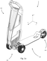
- Figures 1a to 1c and 2b are various views of an entire electric scooter 100 according to a first aspect of the present invention.
- the scooter 100 comprises a deck assembly 102, a tiller assembly 104, a front wheel suspension and steering assembly 106 and a rear wheel assembly 108. Comparing Figures 1a to 1c and Figures 3a and 3b , the scooter 100 can be moved from an unfolded condition where the deck 102 is on the ground with the tiller 104 normal thereto (upright) to a folded condition where the deck and tiller are parallel.
- the deck assembly 102 comprises a deck panel 110 having a front portion 112, rear portion 114 and a central portion 116.
- the front and rear portions 112, 114 are defined by upturned, curved regions 118, 120 respectively, extending at 45 degrees to the flat, planar central portion 116.
- Each of the front and rear portions 112, 114 are also narrower in the lateral direction than the central portion 110, being tapered at the curved regions 118, 120.
- the deck panel 110 is constructed from a composite material to be lightweight and stiff (e.g. carbon fibre reinforced polymer).
- the deck assembly 102 comprises a front deck insert 122 and a rear deck insert 124.
- the deck inserts 122, 124 are constructed from a metal material (so they are able to hold a thread) and embedded in the panel 110 with fixing holes 126, 128 respectively being open to the surface of the deck assembly 102.
- Each deck insert 122, 124 extends through the respective curved region 118, 120.
- the rear deck insert 124 comprises a locking plate 125 constructed from a ferromagnetic material.
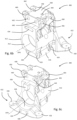
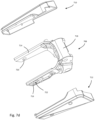
- FIGS 5a to 5k show the tiller 104.
- the tiller 104 comprises:
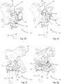
- the tiller pivot and folding subassembly 130 is shown in Figures 5b to 5g .
- the assembly comprises a tiller pivot shaft 138, a tiller mount 348 and a catch 350.
- the tiller pivot shaft comprises a main shaft portion 342 and a head 344 defining a tilt pivot shaft bore 346 ( Figures 5c and 5g ).
- the tiller mount 348 is attached to the main part of the tiller, and moveable therewith.
- the tiller mount 348 is pivotably mounted to the tiller pivot shaft 130 via a tilt pivot shaft 352 which is engaged with the tilt pivot shaft bore 346. This enables the tiller mount 348 (and tiller) to rotate about a folding axis FA.
- the catch 350 comprises two spaced-apart plates either side of the tiller mount 348.
- the catch 350 comprises a pedal 354 rotatable between a stowed position where is sits flush with the tiller mount 348 ( Figure 5d ) and a deployed position rotated 90 degrees to project approximately parallel with the deck. This enables a user's foot to actuate the pedal 354.
- the catch 350 has a pivot pin 356 to enable rotation relative to the tiller mount 348.
- the catch 350 further comprises an abutment shaft 358 ( Figure 5c ).
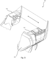
- the battery assembly 134 is shown in Figures 5d and 5e .
- the battery assembly 134 comprises a tiller subassembly 300 and a battery module 302.
- the tiller subassembly comprises electrical power connectors for the transfer of electrical energy from the battery module (e.g. when powering the wheel motors, lights, sounds) and to the battery module when recovering energy from e.g. braking (reverse driving the wheel motors).
- the battery module 302 is configured to be easily installed and removed in the base of the tiller.
- the module 302 comprises a lever 304 which can be lifted in direction L to release a mechanical locking mechanism to allow removal of the module 302 in direction BR. Replacement of the module 302 reconnects the electrical contact between the tiller subassembly 300 and the battery module 302.
- battery module 302 There are three types of battery module 302 with this particular embodiment:
- the standard and high capacity packs are unitary modules that provide predetermined amounts of energy (the high capacity pack simply containing more cells).
- the travel pack has a 320Whr (Watt-hours) energy storage capacity.
- the pack 302 comprises a module carrier 306, a first battery sub-module 308 and a second battery sub-module 310.
- Each sub-module 308, 310 has a capacity of 160Whr. This means that the battery sub-modules 308, 310 may be separate (e.g. by removing both from the carrier 306) and stored in passenger carry-on baggage under CAA (Civil Aviation Authority) rules. This allows the authorised transport of the scooter and associated batteries on aircraft.
- CAA Carrier Aviation Authority
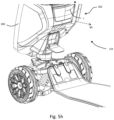
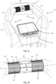
- the control assembly 135 is located at the uppermost part of the tiller (furthest from the deck in the unfolded condition) and is shown in Figures 5g and 5h .
- the control assembly comprises a base region 312 from which first and second arms 314, 316 project vertically upwardly and outwardly at a first portion 318, 320 respectively, upwardly and inwardly at a second portion 322, 324 respectively and meeting a crossbar portion 326 joining the respective free ends.
- the control assembly therefore forms a hexagon shape.
- a user interface 328 is provided mounted to the base region 312 and comprises an information screen which can be used to inform the rider of information such as speed, range remaining etc.
- the screen can also function as an input device to control e.g. sounds, cruise control etc.
- the crossbar 326 comprises the primary driving controls.
- An accelerator / brake control 328 is provided comprising a single rotatable control member 330 rotatable about a horizontal control axis CA (parallel to the crossbar 326).
- the member 330 comprises two spaced-apart control surfaces 332, 334.
- One control surface 332 is proximate the left hand arm 314, and another surface 334 proximate the right hand arm 316.
- the surfaces 332, 334 are cylindrical in shape with depressions 336, 338 formed therein.
- the button array 340 comprises a horn button 342, and a left and right indicator button 344, 346.
- the driving controls are connected and operate as follows.
- the thumbs rest in the depressions 336, 338 and allow the user to rotate the member 330 forwards and rearwards.
- the member 330 is resiliently biased towards the neutral position. Rotation forwards about the axis CA causes power to be delivered from the battery to the wheel motors to accelerate the scooter. Releasing the member 330 will cause the scooter to freewheel, and reversing the direction of rotation (i.e. downwards) will cause braking by harvesting electrical energy from the wheel motor (i.e. acting as generators and charging the battery).
- the user also has the ability to depress the horn 348 and left and right indicators 344, 346 using their thumbs. Because the two surfaces 332, 334 rotate together, the user only needs to keep one thumb engaged and can either rest the other, or use it to depress one of the other buttons.
- the tiller 104 is supported by a spine 132 that extends from a mounting formation 364 at a first end for mounting to the tiller mount 348, via an elongate U-shaped section 366 to a first arm 368 and a second arm 370 forming a "Y" shaped spine.
- the arms 368, 370 extend into the first portions 318, 320 of the arms 314, 316 of the control assembly.
- the spine 132 is provided within the interior of the tiller, and is generally a unitary component. It is therefore stiff, and can react both the bending loads placed on the tiller by the user's hands, as well as transmit the steering torque required during riding.
- Figures 6a to 6k show the front wheel suspension and steering assembly 106.
- the assembly can be separated into the following parts:
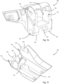
- the central boss 400 is shown in detail in Figures 6b and 6c . It is a unitary component constructed from metal.
- the boss 400 comprises a central cylindrical portion 412 having a through-bore 414 defining a deck pivot axis DPA oriented in a longitudinal direction (parallel to axis X).
- a lower suspension attachment portion 416 is provided directly below the central cylindrical portion 412.
- the portion 416 comprises a left-hand lower suspension attachment bore 418 and a right-hand lower suspension attachment bore 420.
- the bores 418, 420 are offset from each other and parallel with the deck pivot axis DPA and longitudinal axis X.
- Grub screw bores are provided in communication with, and perpendicular to, the bores 418, 420, extending from a lower surface of the portion 416 (not shown).
- the deck support portion 422 comprises a pair of lower suspension attachment bores 424, 426 directly opposite and aligned with the lower suspension attachment bores 418, 420 respectively of the lower suspension attachment portion 416. Only the left hand lower suspension attachment bore 424 is visible in Figure 6b .
- the deck support portion 422 further defines a deck mount bearing surface 428, which is shaped as a concave, part-cylindrical surface.
- a deck mount bearing surface 428 which is shaped as a concave, part-cylindrical surface.
- respective anti-camber spring support wings 430, 432 are provided on the left and right hand sides of the deck support portion 422.
- a rotation-limiting slot 434 On the front surface of the boss 400, directly above the central cylindrical portion 412, extending into the boss 400 parallel to the deck pivot axis DPA there is provided a rotation-limiting slot 434.
- the slot 434 is arcuate and centred on the deck pivot axis DPA.
- An upper suspension attachment portion 438 is provided directly above the central cylindrical portion 412.
- the portion 438 comprises a left-hand upper suspension attachment bore 440 and a right-hand upper suspension attachment bore 442.
- the bores 440, 442 are offset from each other and parallel with the deck pivot axis DPA and longitudinal axis X. They are directly above the respective lower suspension attachment bores 424, 426.
- Grub screw bores 444, 446 are provided in communication with, and perpendicular to, the bores 440, 442, extending from an upper surface of the portion 438.
- each flange defines a respective wishbone attachment bore 456, 458, 460, 462 respectively.
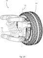
- the left suspension assembly 402 and wheel 404 is shown in Figures 6d to 6f .
- the left suspension assembly is of an independent double-wishbone configuration.
- the assembly comprises a left wheel hub 464, a left upper wheel pivot 466, a left lower wheel pivot 468 a left upper wishbone 470, a left lower wishbone 472 and a left spring-damper assembly 474.
- the left wheel hub 464 comprises a body 476 configured for rotational mounting of the left wheel 402 via a DC electric motor, which is nested inside the wheel itself.
- the DC electric motor is configured to impart a torque to the wheel 404 to drive the wheel in rotation about a front left wheel axis FLW.
- the hub 464 further comprises a mudguard attachment flange 478 extending rearwardly for attachment of a mudguard 480.
- the left wheel hub comprises a steering kingpin receiving bore 482 extending vertically therethrough. Extending forward of the hub there is defined a steering arm 484 defining a vertical steering pin receiving bore 486.
- a rotation limiting pin lug 488 is defined protecting laterally inwardly from the hub 464 defining a pin receiving bore 490.
- the left upper wheel pivot 466 comprises a base portion 492 defining an arcuate slot 494.
- a wishbone mounting lug 496 defining a pivot bore 498 projects upwardly from the base portion 494.
- the left lower wheel pivot 468 comprises a base portion 500.
- a wishbone mounting lug 502 defining a pivot bore 504 projects downwardly from the base portion 500.
- the left upper wishbone 470 is a generally U-shaped member having a forward arm 506 and a rearward arm 508 with aligned pivot bores 510, 512 defined at the free ends thereof. Opposite the free ends, a pivot receiving slot 514 is defined having a throughbore 516 intersecting.
- the left lower wishbone 472 has a body portion 518, a forward arm 520 and a rearward arm 522 with aligned pivot bores 524, 526 defined at the free ends thereof. Opposite the free ends, a pivot receiving slot 528 is defined having a throughbore 530 intersecting. A spring-damper receiving opening 532 is provided in the body portion intersected by a throughbore 534.
- the left spring-damper assembly 474 is known in the art, and will not be described in detail, suffice to say that it comprises a first attachment lug 536 defining a bore 538 and a second attachment lug 540 defining a bore 542.
- the spring-damper assembly 474 is of variable length, being compressible and resilient as known in the art. It also has damping characteristics.
- the right suspension subassembly and wheel are a mirror image of the left suspension subassembly and left wheel, as described above. References to the parts will be made with the prime (')- for example right wheel hub 464'.
- the right wheel 408 rotates about a right wheel rotation axis FRW, which in a neutral steering position is parallel with the left wheel rotation axis FLW.
- the steering subassembly 410 comprises:
- the tiller pivot shaft 138 of the tiller assembly 104 is also shown.
- the front deck mount 544 comprises a deck abutment surface 562 profiled to the underside of the deck 110. Two spaced-apart alignment protrusions 563, 565 extend from an upper edge of the front deck mount 544 such that they project vertically upwards (also see Figure 2a ).
- the deck mount 544 further comprises a shaft-receiving open bore 564 being generally horizontally oriented.
- the tiller pivot 546 comprises a first portion 566 being generally vertical and cylindrical in form, having a pivot shaft bore 568 running therethrough and defining a tiller pivot axis TPA. At the upper end of the first portion there is defined an axially extending spring abutment protrusion 573. Extending tangentially either side of the upper end of the first portion there are provided pivot limit abutments 575, 577.
- a deck pivot shaft 573 extends normal to the first portion 566 and is generally cylindrical with a profiled end 575.
- the left- and right-hand anti-camber spring assemblies 548, 550 comprise compression springs.
- the steering links 552, 554 are mirror images of each other and are generally stiff and capable of transmitting compressive and tensile loads.
- the centring assembly 560 comprises a steering hub 577, a housing 579 and a torsion spring 581.
- the steering hub 577 is generally flat, defining a shaft opening 578 therethrough. Adjacent the shaft opening and projecting upwardly from the steering hub 572 there is provided an arcuate spring abutment 580. Radially outward from the spring abutment 580 there is defined a slot 582. Projecting downwardly from the steering hub 572 there is provided a steering lug 584.
- the housing 581 is generally concave defining a cavity, and a shaft opening 586 therethrough.
- the torsion spring 576 comprising a first spring abutment 588 and a second spring abutment 590.
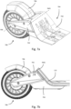
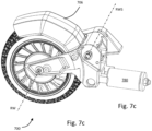
- the rear wheel assembly 108 is shown in Figures 7a to 7g .
- the rear wheel assembly comprises a rear wheel 700, a rear wheel carriage 702, rear deck mount 704, and a brake subassembly 706.
- the rear wheel is generally known in the art and comprises a central bearing arrangement to facilitate rotation about a rear wheel axis RW.
- the rear wheel carriage 702 is shown in more detail in Figure 7d .
- the carriage comprises a rear fork 708, a left hand cover 710 and a right hand cover 712.
- the rear fork 708 is generally U-shaped and comprises a left arm 714, a right arm 716 and a base portion 718.
- Each arm 714, 716 defines an axle receiving bore 720, 722.
- the base portion 718 defines two lower lugs 724, 726 each defining a spring pin receiving bore 728, 730.
- the base portion 718 also defines a brake spring cavity 732 passing therethrough defining a spring abutment 734 and two spaced-apart brake pivot bores 736, 738 on opposite walls thereof.
- the rear deck mount 704 comprises a deck abutment surface 740 profiled to the underside of the deck 110.
- the rear deck mount 704 further defines (referring to Figure 7f ) a mounting portion 742 defining two spaced-apart wheel carrier attachment lugs 744, 746 defining respective bores 748, 750.
- a spring-damper channel 756 is also defined forward of the mounting portion 742.
- An extensible spring-damper 708 is provided.
- the brake subassembly 706 is shown in Figure 7g is comprises a wheel contacting brake member 758 in the form of a mudguard and a torsion spring 772.
- the brake member 758 defines a curved, concave wheel contacting portion 760 and an attachment portion 762 extending outwardly therefrom at one end.
- the attachment portion 762 comprises two spaced apart walls 764, 766 defining spring pin bores 768, 770.
- the torsion spring 772 comprises a first abutment 774 and a pair of second abutments 776, 778 either side thereof.
- the tiller has two positions as shown by contrasting Figures 1a and 3a . Movement between these positions is enabled by the tiller pivot and folding subassembly 130.
- rotation of the tiller is effected by firstly dropping the pedal 354 into the deployed position from Figures 5d to 5e .
- This enables the user to place a foot onto the pedal 354 to thereby rotate the catch 350 in direction C1 ( Figure 5e ).
- This rotates the abutment shaft 358 out of the way of the head 344 of the shaft 138.
- This enables relative rotation of the tiller mount 348 about the folding axis FA, moving from Figure 5e to 5f (dripping the tiller to the position of Figure 3a ).
- the tiller is secured in position against the deck by attraction from a permanent magnet in the tiller attracting the locking plate 125 of the rear deck insert 124. Alignment is ensured by engagement of the male alignment protrusions 563, 565 of the deck with corresponding female recesses 360, 362 on the tiller ( Figure 2a ). Manual force is used to separate the tiller and deck to move back to the unfolded condition.
- the left wheel hub 464 is generally vertically oriented in use, with the wheel 404 mounted thereto via the DC electric motor for rotation about the front left wheel rotation axis FLW.
- the mudguard 480 is attached to the mudguard attachment flange 478 so as to at least partially cover the wheel 404.
- a kingpin (not shown) is provided passing through the steering kingpin receiving bore 482.
- the left upper wheel pivot 466 is attached to the upper end of the kingpin on an upper side of the left wheel hub 464, and the left lower wheel pivot 468 connected to the lower end of the kingpin on the opposite, lower side of the left wheel hub 464.
- the left wheel hub 464 can rotate about the kingpin (and the pivots 466, 468) about a front left wheel steering axis FLS. Rotation about the front left wheel steering axis FLS is limited to a predetermined range by abutment of a steering limiting pin (not shown) inserted into the pin receiving bore 490 of the hub 464 against the ends of the arcuate slot 494 in the left upper wheel pivot 466.
- the left upper wishbone 470 is mounted to the left upper wheel pivot 466 for relative rotation via a pivot pin engaged with the pivot bore 498 of the left upper wheel pivot 466 and the throughbores 516 of the left upper wishbone 470.
- the mounting lug 496 sits in the pivot receiving slot 514 of the left upper wishbone 470.
- the left lower wishbone 472 is mounted to the left lower wheel pivot 468 for relative rotation via a pivot pin engaged with the pivot bore 504 of the left lower wheel pivot 468 and the throughbores 530 of the left lower wishbone 472.
- the mounting lug 502 sits in the pivot receiving slot 528 of the left lower wishbone 472.
- the left spring-damper assembly 474 is mounted at a first end via the first attachment lug 536 to an inboard end of the left upper wishbone 470, and via the second end via the second attachment lug 540 to an outboard end of the left lower wishbone 472.
- This assembly is attached to the central boss 400 as follows.
- the left upper wishbone 470 is mounted to the left hand side of the boss 400 by positioning the wishbone arms either side of the wishbone attachment flanges 448, 450.
- a pivot pin is passed through the aligned bores 460, 462, 510, 512.
- the left lower wishbone 472 is mounted to the left hand side of the boss 400 by positioning the wishbone arms either side of the lower suspension attachment portion 416.
- a pivot pin is passed through the aligned bores 418, 510, 512. The pivot pin extends into the lower suspension attachment bore 424 directly opposite and aligned with the lower suspension attachment bore 418.
- a double-wishbone suspension arrangement is formed to mount the left wheel to the boss 400.
- the wheel 404 is able to move vertically up and down relative to the boss 400 by rotation of the wishbones 470, 472. Upward motion (i.e. downward motion of the vehicle deck) will resiliently extend the spring-damper 474 to provide suspension.
- the left spring-damper assembly 474 has resiliently compressed resulting in a damping force contrary to the direction of motion, and a resilient force acting to restore the wheel position to Figure 8a .
- the steering links 552, 554 have also rotated about their respective end mountings.
- the deck pivot shaft 570 is inserted for rotation about the deck pivot axis DPA into the through-bore 414 of the boss 400 ( Figures 6b and 6c ) to rotationally mount the tiller pivot 546.
- the front deck mount 544 is attached to the end of the deck pivot shaft 570 and fixed thereto such that the deck mount 544 (and deck when attached) are pivotable about the horizontal deck pivot axis DPA relative to the boss 400.
- the rotational position of the deck mount 544 and tiller pivot 546 is resiled back to a neutral position by the use of the two anti-camber spring assemblies 548, 550 that are positioned in compression between the respective anti-camber spring support wings 430, 432 of the boss 400 at the lower ends, and the deck mount 544 at the upper ends.
- the tiller pivot shaft 138 is mounted for rotation about the tiller pivot axis TPA in the pivot shaft bore 568 of the tiller pivot 546. Also mounted on the tiller pivot shaft is the centring assembly 560.
- the steering hub 572 and housing 574 encapsulate the torsion spring 576.
- the centring assembly 560 is mounted for rotation with the tiller pivot.
- the centring assembly 560 has several functions. Firstly, the spring abutment protrusion 573 of the tiller pivot 546 is received in the slot 582 and acts as an abutment for either of the spring abutments 588, 590.
- the separation of the (stationary) spring abutment protrusion and moving spring abutment 580 of the steering hub 572 acts to tension the spring, which tries to realign them.
- the steering hub 572 acts as a rotation limit stop as at a predetermined rotational limit (in either direction), the steering lug 584 will abut either stationary pivot limit abutment 575, 577.
- the steering links 552, 554 are mounted for rotation about a vertical axis from the underside of the steering lug 584 of the steering hub 572.
- the steering links 552, 554 are both connected to the steering lug 584 at a respective first end, and to respective steering arms of the wheel hubs at a respective second end. Attachment to the steering hubs is via a pivot shaft engaged with the steering pin receiving bore 486 (for example on the arm 484 of the left hand hub).
- the wheel hubs are rotatable about respective vertical steering axes. Therefore lateral movement of the steering lug either right or left will have the effect of rotating the wheels about their respective steering axes.
- the horizontal distance F1 between the steering axes FLS, FRS is less than the distance F2 between the axes of rotation between the steering links 552, 554 and the respective steering lugs 584, 584'.
- This provides so-called “Ackermann” steering- i.e. when the wheels are turned in a specific direction, the innermost wheel (closest to the centre of the turning circle) will rotate about the steering axis more than the outer wheel.
- F1 ⁇ F2 because the steering links are forward of the kingpins. It will be noted that if the steering links are rearward of the kingpins then F1 > F2 for Ackermann steering.
- Such lateral movement of the steering lug 584 relative to the boss 400 (to which the suspension is attached) occurs in two ways, or steering modes:
- the first mode is 'tiller rotation'.
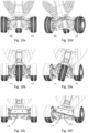
- Figures 9a to 9d show this.
- the scooter 100 is in a neutral "wheels forward" position.
- the second mode is 'deck roll'.
- Figures 10a to 10f show this mode. Note that Figures 10c and 10f show a section through the centre of the deck 110. Figures 10a to 10c show the scooter 100 in a neutral position.
- the deck 110 and therefore the deck mount 544 are rotated by the rider's feet (much like a skateboard or snowboard) such that rotation of the 110 and the deck tiller pivot 546 about the deck pivot axis DPA occurs (note that the deck pivot axis is shown in Figure 9b for clarity).
- This causes sideways, arcuate motion of the steering lug 584 which acts to steer the wheels simultaneously about their respective steering axes FLS, FRS.
- both modes act to actuate the steering lug 584 which steers the wheels. It will be noted with reference to Figure 6h that the horizontal distance between the tiller pivot axis TPA and the steering lug 546 is less than the vertical distance between the deck pivot axis DPA and the steering lug 546.
- the rear wheel 700 is mounted for rotation about the rear wheel axis RW between the arms 714, 716 of the rear fork 708.
- the entire rear wheel carriage 702 (of which the fork 708 is a part) is mounted to the rear deck mount 704 for rotation about a rear wheel suspension axis RWS.
- the spring-damper 780 is nested within the spring-damper channel 756, attached to the rear deck mount 704 at a first end and to the fork 708 at a second end (specifically via the spring spin receiving bores 728, 730).
- the rear brake 706 can be depressed against the rear wheel 700 against the bias of the spring 772 to provide a frictional braking force as known in the art. This is generally used as an "emergency" brake, as most braking is carried out by reverse-driving the front wheel motors to recover energy into the batteries.
- FIG. 11 a second scooter 1100 is shown in accordance with the present invention.
- the scooter 1100 comprises a deck assembly 1102, a tiller assembly 1104, a front wheel suspension and steering assembly 1106 and a rear wheel assembly 1108.
- the second embodiment is identical to the first embodiment with the exception of the rear wheel assembly 1108.
- reference numerals relating to the deck assembly 1102, tiller assembly 1104, and the front wheel suspension and steering assembly 1106 features will be numbered per the scooter 100, but 1000 greater.
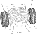
- Figures 12a to 12g show the rear wheel suspension and steering assembly 1108.
- the assembly can be separated into the following parts:
- the mounting subassembly 1800 comprises a rear deck mount 1812, a rear boss 1814, a deck pivot shaft 1816 and left and right anti-camber springs 1818, 1820.
- the deck mount 1812 comprises a deck abutment surface 1822 profiled to the underside of the deck 110.
- the rear deck mount 1812 further defines a deck pivot shaft opening 1824 extending in a generally longitudinal direction along the deck pivot axis DPA.
- the deck mount 1822 further defines two downwardly-facing camber spring attachment points 1826, 1828.
- the rear boss 1814 comprises a pivot shaft throughbore 1830 extending along the deck pivot axis DPA. It also defines two spaced-apart upwardly-facing camber spring attachment points 1832, 1834, either side of the axis DPA.
- the boss 1814 defines a lower wishbone attachment lug 1836, an upper wishbone attachment lug 1838 and two spaced apart spring-damper attachment flanges 1840, 1842, 1844, 1846 on either side of the upper wishbone attachment lug 1838.
- the deck pivot shaft 1816 is generally hollow and cylindrical having a tapered front end 1848, and a flat rear end 1850 into which a plug 1852 is inserted.
- the left suspension subassembly 1802 is shown.
- the left suspension subassembly 1802 is of an independent double-wishbone configuration.
- the assembly comprises a left wheel hub 1854, a left upper wheel pivot 1856, a left lower wheel pivot 1858 a left upper wishbone 1860, a left lower wishbone 1862 and a left spring-damper assembly 1864.
- the left wheel hub 1854 comprises a body 1866 configured for rotational mounting of the left wheel 1804 about a rear left wheel axis RLW.
- the body 1866 defines a steering arm 1868 extending rearwardly therefrom.
- the pivots 1856, 1858 are mounted above and below the body 1866 and joined by a steering kingpin for rotation relative thereto about a rear left wheel steering axis RLS
- the upper, lower wishbones 1860, 1862 and spring damper assembly 1864 are similar to those on the front suspension and will not be described in detail.
- the right suspension subassembly and wheel are a mirror image of the left suspension subassembly and left wheel, as described above. References to the parts will be made with the prime (')- for example right wheel hub 1866'.
- the right wheel 1804' rotates about a right wheel rotation axis RRW, which in a neutral steering position is parallel with the left wheel rotation axis RLW.
- the steering subassembly 1806 comprises:
- the deck pivot cam 1870 is a generally flat plate having a pivot shaft receiving formation 1876, and an eccentric portion 1878 comprising a first set of link openings 1880 at a first radius r1 from the deck pivot axis DPA and a second set of link openings 1882 at a second, greater radius from the deck pivot axis DPA.
- the left and right hand steering links 1872, 1874 comprise respective ball joints 1884, 1886 at a medial end and respective ball joints 1888, 1890 at a lateral end.
- the deck pivot shaft 1816 is attached to the deck mount 1812 by attachment inside the opening 1824. It is then inserted into the throughbore 1830 in the boss 1814 such that the deck mount 1812 (and deck 110 attached thereto) can rotate about the deck pivot axis DPA.
- the relative rotation between the deck mount 1812 and the boss 1814 is controlled by the two anti-camber springs 1818, 1820 extending between the points 1826, 1832 and 1828, 1834 respectively.
- the mount 1812 and boss 1814 are resiliently biased to a neutral position (per Figure 12a ).
- the left and right suspension subassemblies 1802, 1806 are attached to the boss 1814.
- the upper wishbones 1860, 1860' are attached to the upper wishbone lug 1838, and the lower wishbones 1862, 1862' attached to the lower wishbone lug 1836.
- the wishbones are mounted for rotation relative to the boss about axes parallel to the direction of travel X.
- the spring-damper assemblies 1864, 1864' are positioned to extend between the spring damper attachment flanges 1840, 1842, 1844, 1846 of the boss 1814 and the lower wishbones 1862, 1862'.
- the deck pivot cam 1870 is mounted to rotate with the shaft 1816, on the opposite side of the boss 1814 to the deck 110.
- the steering links 1872, 1874 extend in opposite directions from the second set of link openings 1882 to the upper side of the steering arms 1868, 1868' on each respective hub 1854, 1854'.
- the left spring-damper assembly 1864 has resiliently compressed resulting in a damping force contrary to the direction of motion, and a resilient force acting to restore the wheel position to Figure 13a .
- the steering links 1872, 1874 have also rotated about their respective end mountings.
- the rear steering capability is responsive to deck roll only (unlike the front wheels that are responsive to deck roll and tiller pivot).
- rotation of the deck in a clockwise direction about the deck pivot axis DPA rotates the deck pivot shaft 1816 in the boss 1814 against the bias of the anti-camber springs 1818, 1820.
- this lean to the right causes the front wheels to rotate to steer to the right (i.e. in a clockwise direction about their respective steering axes FLS, FRS in plan).
- Such motion acts to move the eccentric portion 1878 of the deck pivot cam 1870.
- the horizontal distance R1 between the steering axes RLS, RRS is less than the distance R2 between the axes of rotation between the steering links 1872, 1874 and the respective steering lugs 1868, 1868'.
- This provides so-called “Ackermann” steering- i.e. when the wheels are turned in a specific direction, the innermost wheel (closest to the centre of the turning circle) will rotate about the steering axis more than the outer wheel.
- R1 ⁇ R2 because the steering links are forward of the kingpins. It will be noted that if the steering links are rearward of the kingpins then R1 > R2 for Ackermann steering.
- the rear steering subassembly 1810 can be adjusted to provide a different level of rear steering assistance to the rider.
- Figure 15a is configured as above- i.e. with the steering links 1872, 1874 extending in opposite directions from the second set of link openings 1882 to the upper side of the steering arms 1868, 1868' on each respective hub 1854, 1854'.
- the links 1872, 1874 have been removed and replaced extending in opposite directions from the first set of link openings 1880 to the lower side of the steering arms 1868, 1868' on each respective hub 1854, 1854'.
- the lower radius of the first openings 1880 means that rotation of the deck will provide a much lower degree of movement for the links 1872, 1874 thus producing a lesser rear steer effect. This is useful for e.g. beginners, and those who are less interested in "carving" turns with the deck lean mode of steering.
Landscapes
- Engineering & Computer Science (AREA)
- Mechanical Engineering (AREA)
- Chemical & Material Sciences (AREA)
- Combustion & Propulsion (AREA)
- Transportation (AREA)
- Automatic Cycles, And Cycles In General (AREA)
- Motorcycle And Bicycle Frame (AREA)
- Axle Suspensions And Sidecars For Cycles (AREA)
- Arrangement Or Mounting Of Propulsion Units For Vehicles (AREA)
Description
- The present invention is concerned with a motorised scooter. More specifically, the present invention is concerned with an electric scooter.
- By "scooter" we mean a stand-up scooter or 'kick' scooter, rather than a motorcycle-type scooter. Scooters according to the present invention are distinguished in having a deck, generally proximate and parallel to the floor with wheels mounted thereon. An upright or 'tiller' is provided extending vertically upward from the forward end of the deck featuring handlebars to facilitate stability and steering.
- Traditionally such scooters have been human-powered, specifically by pushing the scooter along with one foot whilst the other (load-bearing) foot remains on the deck. More recently, motorised scooters have appeared on the market. Initial designs utilised internal combustion engines, but battery-powered electric scooters have grown in popularity since the early 2010s and represent a fast, efficient, environmentally friendly and convenient way to travel.
-
US 9 610 998 B1 - Some kick scooters (in particular those marketed towards the junior market) typically have a single front wheel and a single rear wheel. They utilised a simple steering system in which rotation of the tiller about a vertical axis, using the handlebars, would also rotate the front wheel.
- One such known scooter is the Moove (TM) range of scooters. These battery powered electric scooters are of a two wheel design (front and rear) with the front wheel pivoting about a substantially vertical axis to steer. Rotation of the handlebars about that axis rotates the front wheel. These products are based on traditional two-wheeled "trick" scooters.
- The Bajaboard (TM), although not a scooter per se, is a four-wheeled electric skateboard designed for off-road use. It can be steered by rotating the board about a longitudinal or horizontal axis (i.e. "leaning" on the board).
- The Cycleboard (TM) is a three-wheeled electric scooter that features a "lean to steer" steering system. Two wheels are provided at the front, and one at the rear.
US 9,610,988 B1 -
US 9,610,988 B1 - A mechanism is provided such that when the deck is leaned to the side about the roll axis, the wheels turn about their respective steering axes (in the same direction as the roll). The mechanism has a steering transmission arm pivoted to the frame at a first end, coupled to the deck at a mi-point and attached to two steering rods at a second end. When the deck is rotated about the horizontal axis, the steering transmission arm is driven in rotation and as such drives the steering arms to rotate the respective wheels about their respective steering axes.
- Essentially, there are two types of steering provided in the prior art. One type is "vertical pivot" steering found on most two-wheeled trick scooters. This type of steering is useful for low speed movements and tricks because it is highly sensitive and can offer a high degree of maneuverability. The other type is "lean to steer" steering found on three-wheeled off-road and high-speed electric scooters. This type of steering is suitable for high-speed, stable "carving" turns, but lacks manoeuvrability at low speeds. Indeed, performing tight turns at low speed would require the rider to roll the deck to a significant degree which would be difficult.
- It is an aim of the present invention to overcome, or at least mitigate the aforementioned problems with the prior art.
- According to a first aspect of the invention there is provided a scooter according to claim 1.
- Advantageously, this dual mode steering provides both the ability to provide a high degree of manoeuvrability in the first mode for low speeds, and a 'carving' high speed mode of steering using deck roll. Both modes can be used together, without having to switch any controls on the scooter.
- By "first mode of steering" and "second mode of steering" we do not mean that a positive control is required to switch between two modes- rather that the steering can be operated using the first mode and / or the second mode. In other words, the modes can be utilised independently or simultaneously at any point during use of the scooter at the rider's preference.
- Preferably a central boss is provided, wherein;
- the tiller is mounted for rotation relative to the central boss about the vertical axis; and,
- the deck is mounted for rotation relative to the central boss about the horizontal axis.
- Preferably the steering system comprises a pair or steering arms connected to respective front wheels, the steering arms being connected to a steering hub, wherein the steering hub is configured to move with rotation of the tiller in the first steering mode, and with rotation of the deck in the second steering mode.
- Preferably the steering hub is mounted for rotation with the tiller, the tiller is mounted for rotation in a tiller pivot member about the vertical axis, and the tiller pivot member is mounted for rotation in the central boss about the horizontal axis.
- Preferably a resilient centring mechanism is provided for resiling the tiller to a predetermined neutral rotational position relative to the central boss.
- Preferably an anti-camber mechanism is provided for resiling the deck to a predetermined neutral rotational position relative to the central boss.
- Preferably the two front wheels are mounted to the central boss via a suspension system.
- Preferably the suspension system is a double-wishbone suspension system.
- Preferably the rear wheel is mounted for rotation in a rear wheel mount, and in which the deck is rotatable about the horizontal axis about the rear wheel mount.
- There is also an embodiment having four wheels, in which a pair of rear wheels and a rear steering mechanism is provided configured to steer the two rear wheels about respective steering axes.
- Preferably rotation of the deck about the horizontal axis steers the wheels.
- Preferably rotation of the deck about the horizontal axis causes the front wheels to steer in a first direction about their respective steering axes, and causes the rear wheels to steer a second, opposite, direction about their respective steering axes.
- Preferably the rear steering system is configured to steer the rear wheels in the second mode of steering but not in the first mode of steering.
- Preferably the rear steering mechanism is adjustable to provide at least two steering settings, in which each steering steers the wheels by a different angle in response to a predetermined degree of deck roll.
- Preferably the rear steering mechanism is configured for Ackermann steering.
- Preferably the front steering mechanism is configured for Ackermann steering.
- Example scooters in accordance with the present invention will now be described with reference to the accompanying drawings in which:
-
Figure 1a is a first perspective view of a first scooter in accordance with the present invention in an unfolded condition; -
Figure 1b is a second perspective view of the scooter ofFigure 1 ; -
Figure 1c is an underside view of the scooter ofFigure 1 ; -
Figure 2a is a detail view of a part of the scooter ofFigure 1 ; -
Figure 3a is a perspective view of the scooter ofFigure 1 in a folded condition lying flat; -
Figure 3b is a perspective view of the scooter ofFigure 1 in a folded upright condition; -
Figure 4 is a perspective view of the deck assembly of the scooter ofFigure 1 ; -
Figure 5a is a perspective view of the tiller of the scooter ofFigure 1 ; -
Figure 5b is a detailed view of a part of the tiller ofFigure 5a ; -
Figure 5c is a detail section view of a part of the tiller ofFigure 5a ; -
Figure 5d is a perspective view of the hinge mechanism of the tiller ofFigure 5a in a first condition; -
Figure 5e is a perspective view of the hinge mechanism of the tiller ofFigure 5a in a second condition; -
Figure 5f is a perspective view of the hinge mechanism of the tiller ofFigure 5a in a third condition; -
Figure 5g is a perspective view of the hinge mechanism of the tiller ofFigure 5a in a fourth condition; -
Figure 5h is a perspective view of a part of the tiller ofFigure 5a ; -
Figure 5i is a partially exploded perspective view of a battery pack of the tiller ofFigure 5a ; -
Figure 5j is a perspective detail view of a control area of the tiller ofFigure 5a ; -
Figure 5k is a perspective detail view of a control area of the tiller ofFigure 5a ; -
Figure 5l is a perspective view of an internal component of the tiller ofFigure 5a ; -
Figure 6a is a perspective view of the front wheel suspension and steering assembly of the scooter ofFigure 1 ; -
Figures 6b and 6c are perspective views of a part of the front wheel suspension and steering assembly ofFigure 6a ; -
Figures 6d and 6e are views from the front and rear respectively of the front wheel suspension and steering assembly ofFigure 6a ; -
Figure 6f is a perspective view of the front wheel suspension and steering assembly ofFigure 6a ; -
Figure 6g is an exploded view of various parts of the front and rear respectively of the front wheel suspension and steering assembly ofFigure 6a ; -
Figures 6h and6i are perspective views of various parts of the front and rear respectively of the front wheel suspension and steering assembly ofFigure 6a ; -
Figure 6j is and exploded view of various parts of the front and rear respectively of the front wheel suspension and steering assembly ofFigure 6a ; -
Figure 6k is a detail view of various parts of the front and rear respectively of the front wheel suspension and steering assembly ofFigure 6a ; -
Figure 6l is an underside view of various parts of the front wheel suspension and steering assembly ofFigure 6a ; -
Figure 7a is a perspective view of the rear wheel assembly of the scooter ofFigure 1 ; -
Figure 7b is a side view of the rear wheel assembly ofFigure 7a ; -
Figure 7c is a perspective view of some parts of the rear wheel assembly ofFigure 7a ; -
Figure 7d is an exploded view of some parts of the rear wheel assembly ofFigure 7a ; -
Figures 7e and 7f are perspective views of a part of the rear wheel assembly ofFigure 7a ; -
Figure 7g is a perspective view of some parts of the rear wheel assembly ofFigure 7a ; -
Figure 8a is a front view of a part of the scooter ofFigure 1 in a neutral condition; -
Figure 8b is a front view of a part of the scooter ofFigure 1 in an articulated condition of the front suspension; -
Figures 9a and9b are front and underside views respectively of the scooter ofFigure 1 in a neutral condition; -
Figures 9c and9d are front and underside views respectively of the scooter ofFigure 1 in a first steering mode; -
Figures 10a to 10c are front, rear and rear section views respectively of the scooter ofFigure 1 in a neutral condition; -
Figures 10d to 10f are front, rear and rear section views respectively of the scooter ofFigure 1 in a second steering mode; -
Figure 11 is a first perspective view of a second scooter in accordance with the present invention; -
Figure 12a is a detail view of a portion of the scooter ofFigure 11 ; -
Figure 12b is an exploded perspective view of various components of the scooter ofFigure 11 ; -
Figures 12c and 12d are perspective view of a subassembly of the scooter ofFigure 11 ; -
Figure 12e is a perspective view of the rear left suspension assembly of the scooter ofFigure 11 ; -
Figure 12f is a perspective view of the rear right suspension assembly of the scooter ofFigure 11 ; -
Figure 12g is a perspective view of the rear steering assembly of the scooter ofFigure 11 ; -
Figure 13a is a rear view of a part of the scooter ofFigure 11 in a neutral condition; -
Figure 13b is a rear view of a part of the scooter ofFigure 11 in an articulated condition of the rear suspension; -
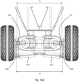
Figure 14a is a rear view of a part of the scooter ofFigure 11 in a neutral condition; -
Figure 14b is a rear view of a part of the scooter ofFigure 11 in an articulated condition of the rear steering system; -
Figure 14c is a plan view of the scooter ofFigure 11 in an articulated condition of the rear steering system; -
Figure 14d is a plan view of the scooter ofFigure 11 in a tiller pivot steering mode; -
Figure 14e is an underside view of the rear steering system; -
Figure 15a is a rear view of a part of the scooter ofFigure 11 in a first setting of the steering system; and, -
Figure 15b is a rear view of a part of the scooter ofFigure 11 in a second setting of the steering system. -
Figures 1a to 1c and 2b are various views of an entireelectric scooter 100 according to a first aspect of the present invention. For the purposes of the present disclosure it is useful to define global directions and axes as follows: - Direction of forward travel along horizontal longitudinal axis X;
- ∘ Rotation about this axis is "roll";
- Lateral direction along horizontal axis Y;
- ∘ Rotation about this axis is "pitch";
- Vertical direction along vertical axis Z;
- ∘ Rotation about this axis is "yaw".
- The
scooter 100 comprises adeck assembly 102, atiller assembly 104, a front wheel suspension andsteering assembly 106 and arear wheel assembly 108. ComparingFigures 1a to 1c andFigures 3a and3b , thescooter 100 can be moved from an unfolded condition where thedeck 102 is on the ground with thetiller 104 normal thereto (upright) to a folded condition where the deck and tiller are parallel. - Referring to
Figure 4 , thedeck assembly 102 is shown. - The
deck assembly 102 comprises adeck panel 110 having afront portion 112,rear portion 114 and acentral portion 116. The front andrear portions curved regions central portion 116. Each of the front andrear portions central portion 110, being tapered at thecurved regions deck panel 110 is constructed from a composite material to be lightweight and stiff (e.g. carbon fibre reinforced polymer). - The
deck assembly 102 comprises afront deck insert 122 and arear deck insert 124. The deck inserts 122, 124 are constructed from a metal material (so they are able to hold a thread) and embedded in thepanel 110 with fixingholes deck assembly 102. Eachdeck insert curved region - The
rear deck insert 124 comprises alocking plate 125 constructed from a ferromagnetic material. -
Figures 5a to 5k show thetiller 104. Thetiller 104 comprises: - A tiller pivot and folding assembly 130 (
Figures 5b to 5g ); - A battery assembly 134 (
Figures 5h and5i ); - A control assembly 135 (
Figures 5j and 5k ); and, - A spine 132 (
Figure 5l ). - The tiller pivot and
folding subassembly 130 is shown inFigures 5b to 5g . The assembly comprises atiller pivot shaft 138, atiller mount 348 and acatch 350. - The tiller pivot shaft comprises a
main shaft portion 342 and ahead 344 defining a tilt pivot shaft bore 346 (Figures 5c and5g ). - The
tiller mount 348 is attached to the main part of the tiller, and moveable therewith. Thetiller mount 348 is pivotably mounted to thetiller pivot shaft 130 via atilt pivot shaft 352 which is engaged with the tilt pivot shaft bore 346. This enables the tiller mount 348 (and tiller) to rotate about a folding axis FA. - The
catch 350 comprises two spaced-apart plates either side of thetiller mount 348. Thecatch 350 comprises a pedal 354 rotatable between a stowed position where is sits flush with the tiller mount 348 (Figure 5d ) and a deployed position rotated 90 degrees to project approximately parallel with the deck. This enables a user's foot to actuate thepedal 354. Thecatch 350 has apivot pin 356 to enable rotation relative to thetiller mount 348. Thecatch 350 further comprises an abutment shaft 358 (Figure 5c ). - The
battery assembly 134 is shown inFigures 5d and 5e . Thebattery assembly 134 comprises atiller subassembly 300 and abattery module 302. The tiller subassembly comprises electrical power connectors for the transfer of electrical energy from the battery module (e.g. when powering the wheel motors, lights, sounds) and to the battery module when recovering energy from e.g. braking (reverse driving the wheel motors). - The
battery module 302 is configured to be easily installed and removed in the base of the tiller. Themodule 302 comprises a lever 304 which can be lifted in direction L to release a mechanical locking mechanism to allow removal of themodule 302 in direction BR. Replacement of themodule 302 reconnects the electrical contact between thetiller subassembly 300 and thebattery module 302. - There are three types of
battery module 302 with this particular embodiment: - A travel pack (module 302);
- A standard capacity pack; and,
- A high capacity pack.
- The standard and high capacity packs are unitary modules that provide predetermined amounts of energy (the high capacity pack simply containing more cells).
- The travel pack, embodiment in
module 302, has a 320Whr (Watt-hours) energy storage capacity. Thepack 302 comprises amodule carrier 306, a first battery sub-module 308 and asecond battery sub-module 310. Each sub-module 308, 310 has a capacity of 160Whr. This means that thebattery sub-modules 308, 310 may be separate (e.g. by removing both from the carrier 306) and stored in passenger carry-on baggage under CAA (Civil Aviation Authority) rules. This allows the authorised transport of the scooter and associated batteries on aircraft. - The
control assembly 135 is located at the uppermost part of the tiller (furthest from the deck in the unfolded condition) and is shown inFigures 5g and5h . The control assembly comprises abase region 312 from which first andsecond arms first portion second portion crossbar portion 326 joining the respective free ends. The control assembly therefore forms a hexagon shape. - A
user interface 328 is provided mounted to thebase region 312 and comprises an information screen which can be used to inform the rider of information such as speed, range remaining etc. The screen can also function as an input device to control e.g. sounds, cruise control etc. - The
crossbar 326 comprises the primary driving controls. An accelerator /brake control 328 is provided comprising a singlerotatable control member 330 rotatable about a horizontal control axis CA (parallel to the crossbar 326). Themember 330 comprises two spaced-apartcontrol surfaces control surface 332 is proximate theleft hand arm 314, and anothersurface 334 proximate theright hand arm 316. Thesurfaces depressions - Between the
surfaces button array 340. Thebutton array 340 comprises ahorn button 342, and a left andright indicator button - The driving controls are connected and operate as follows.
- The user grips the
second portions arms control surfaces buttons depressions member 330 forwards and rearwards. Themember 330 is resiliently biased towards the neutral position. Rotation forwards about the axis CA causes power to be delivered from the battery to the wheel motors to accelerate the scooter. Releasing themember 330 will cause the scooter to freewheel, and reversing the direction of rotation (i.e. downwards) will cause braking by harvesting electrical energy from the wheel motor (i.e. acting as generators and charging the battery). - The user also has the ability to depress the
horn 348 and left andright indicators surfaces - Referring to
Figure 5l , thetiller 104 is supported by aspine 132 that extends from a mountingformation 364 at a first end for mounting to thetiller mount 348, via an elongateU-shaped section 366 to afirst arm 368 and asecond arm 370 forming a "Y" shaped spine. Thearms first portions arms spine 132 is provided within the interior of the tiller, and is generally a unitary component. It is therefore stiff, and can react both the bending loads placed on the tiller by the user's hands, as well as transmit the steering torque required during riding. -
Figures 6a to 6k show the front wheel suspension andsteering assembly 106. - The assembly can be separated into the following parts:
- A central boss 400 (
Figures 6b and 6c ); - A
left suspension subassembly 402 and left wheel 404 (Figure 6d to 6g ); - A
right suspension subassembly 406 andright wheel 408; and, - A steering subassembly 410 (
Figures 6h to 6k ). - The
central boss 400 is shown in detail inFigures 6b and 6c . It is a unitary component constructed from metal. Theboss 400 comprises a centralcylindrical portion 412 having a through-bore 414 defining a deck pivot axis DPA oriented in a longitudinal direction (parallel to axis X). - Referring to
Figure 6b , a lowersuspension attachment portion 416 is provided directly below the centralcylindrical portion 412. Theportion 416 comprises a left-hand lower suspension attachment bore 418 and a right-hand lower suspension attachment bore 420. Thebores bores - Extending below, and rearwardly of the central
cylindrical portion 412 there is provided adeck support portion 422. Thedeck support portion 422 comprises a pair of lower suspension attachment bores 424, 426 directly opposite and aligned with the lower suspension attachment bores 418, 420 respectively of the lowersuspension attachment portion 416. Only the left hand lower suspension attachment bore 424 is visible inFigure 6b . - The
deck support portion 422 further defines a deckmount bearing surface 428, which is shaped as a concave, part-cylindrical surface. On the left and right hand sides of thedeck support portion 422 are provided respective anti-camberspring support wings - On the front surface of the
boss 400, directly above the centralcylindrical portion 412, extending into theboss 400 parallel to the deck pivot axis DPA there is provided a rotation-limitingslot 434. Theslot 434 is arcuate and centred on the deck pivot axis DPA. - On the rear surface of the
boss 400, directly above the centralcylindrical portion 412, and extending rearwardly parallel to the deck pivot axis DPA there is provided a rotation-limitingprotrusion 436. - An upper
suspension attachment portion 438 is provided directly above the centralcylindrical portion 412. Theportion 438 comprises a left-hand upper suspension attachment bore 440 and a right-hand upper suspension attachment bore 442. Thebores bores portion 438. - Extending laterally either side of the
portion 438 there are provided two parallel left-hand upperwishbone attachment flanges wishbone attachment flanges - The
left suspension assembly 402 andwheel 404 is shown inFigures 6d to 6f . The left suspension assembly is of an independent double-wishbone configuration. - The assembly comprises a
left wheel hub 464, a leftupper wheel pivot 466, a left lower wheel pivot 468 a leftupper wishbone 470, a leftlower wishbone 472 and a left spring-damper assembly 474. - The
left wheel hub 464 comprises abody 476 configured for rotational mounting of theleft wheel 402 via a DC electric motor, which is nested inside the wheel itself. The DC electric motor is configured to impart a torque to thewheel 404 to drive the wheel in rotation about a front left wheel axis FLW. - The
hub 464 further comprises amudguard attachment flange 478 extending rearwardly for attachment of amudguard 480. - The left wheel hub comprises a steering
kingpin receiving bore 482 extending vertically therethrough. Extending forward of the hub there is defined asteering arm 484 defining a vertical steeringpin receiving bore 486. - A rotation limiting
pin lug 488 is defined protecting laterally inwardly from thehub 464 defining apin receiving bore 490. - The left
upper wheel pivot 466 comprises abase portion 492 defining anarcuate slot 494. Awishbone mounting lug 496 defining a pivot bore 498 projects upwardly from thebase portion 494. - The left
lower wheel pivot 468 comprises abase portion 500. Awishbone mounting lug 502 defining a pivot bore 504 projects downwardly from thebase portion 500. - The left
upper wishbone 470 is a generally U-shaped member having aforward arm 506 and arearward arm 508 with aligned pivot bores 510, 512 defined at the free ends thereof. Opposite the free ends, apivot receiving slot 514 is defined having athroughbore 516 intersecting. - The left
lower wishbone 472 has abody portion 518, aforward arm 520 and arearward arm 522 with aligned pivot bores 524, 526 defined at the free ends thereof. Opposite the free ends, apivot receiving slot 528 is defined having athroughbore 530 intersecting. A spring-damper receiving opening 532 is provided in the body portion intersected by athroughbore 534. - The left spring-
damper assembly 474 is known in the art, and will not be described in detail, suffice to say that it comprises afirst attachment lug 536 defining abore 538 and asecond attachment lug 540 defining abore 542. The spring-damper assembly 474 is of variable length, being compressible and resilient as known in the art. It also has damping characteristics. - The right suspension subassembly and wheel are a mirror image of the left suspension subassembly and left wheel, as described above. References to the parts will be made with the prime (')- for example right wheel hub 464'. The
right wheel 408 rotates about a right wheel rotation axis FRW, which in a neutral steering position is parallel with the left wheel rotation axis FLW. - The
steering subassembly 410 comprises: - a
front deck mount 544; - a
tiller pivot 546; - a left-hand
anti-camber spring assembly 548; - a right-hand
anti-camber spring assembly 550; - a left-
hand steering link 552; - a right
hand steering link 554; - a left-hand steering link central pivot 556 (
Figure 6k ); - a right-hand steering link central pivot 558 (
Figure 6k ); - a centring assembly 560 (
Figure 6j ). - The
tiller pivot shaft 138 of thetiller assembly 104 is also shown. - The
front deck mount 544 comprises adeck abutment surface 562 profiled to the underside of thedeck 110. Two spaced-apartalignment protrusions front deck mount 544 such that they project vertically upwards (also seeFigure 2a ). Thedeck mount 544 further comprises a shaft-receivingopen bore 564 being generally horizontally oriented. - The
tiller pivot 546 comprises afirst portion 566 being generally vertical and cylindrical in form, having a pivot shaft bore 568 running therethrough and defining a tiller pivot axis TPA. At the upper end of the first portion there is defined an axially extendingspring abutment protrusion 573. Extending tangentially either side of the upper end of the first portion there are providedpivot limit abutments deck pivot shaft 573 extends normal to thefirst portion 566 and is generally cylindrical with a profiledend 575. - The left- and right-hand
anti-camber spring assemblies - The steering links 552, 554 are mirror images of each other and are generally stiff and capable of transmitting compressive and tensile loads.
- The
centring assembly 560 comprises asteering hub 577, a housing 579 and atorsion spring 581. - The
steering hub 577 is generally flat, defining ashaft opening 578 therethrough. Adjacent the shaft opening and projecting upwardly from thesteering hub 572 there is provided anarcuate spring abutment 580. Radially outward from thespring abutment 580 there is defined aslot 582. Projecting downwardly from thesteering hub 572 there is provided asteering lug 584. - The
housing 581 is generally concave defining a cavity, and ashaft opening 586 therethrough. - The
torsion spring 576 comprising afirst spring abutment 588 and asecond spring abutment 590. - The
rear wheel assembly 108 is shown inFigures 7a to 7g . - The rear wheel assembly comprises a
rear wheel 700, arear wheel carriage 702,rear deck mount 704, and abrake subassembly 706. - The rear wheel is generally known in the art and comprises a central bearing arrangement to facilitate rotation about a rear wheel axis RW.
- The
rear wheel carriage 702 is shown in more detail inFigure 7d . The carriage comprises arear fork 708, aleft hand cover 710 and aright hand cover 712. Therear fork 708 is generally U-shaped and comprises aleft arm 714, aright arm 716 and abase portion 718. Eacharm base portion 718 defines twolower lugs pin receiving bore base portion 718 also defines abrake spring cavity 732 passing therethrough defining aspring abutment 734 and two spaced-apart brake pivot bores 736, 738 on opposite walls thereof. - The
rear deck mount 704 comprises adeck abutment surface 740 profiled to the underside of thedeck 110. Therear deck mount 704 further defines (referring toFigure 7f ) a mountingportion 742 defining two spaced-apart wheel carrier attachment lugs 744, 746 definingrespective bores lugs rear abutment arms portion 742. An extensible spring-damper 708 is provided. - The
brake subassembly 706 is shown inFigure 7g is comprises a wheel contactingbrake member 758 in the form of a mudguard and atorsion spring 772. Thebrake member 758 defines a curved, concavewheel contacting portion 760 and anattachment portion 762 extending outwardly therefrom at one end. Theattachment portion 762 comprises two spaced apartwalls torsion spring 772 comprises afirst abutment 774 and a pair ofsecond abutments - The tiller has two positions as shown by contrasting
Figures 1a and3a . Movement between these positions is enabled by the tiller pivot andfolding subassembly 130. - Starting at the position of
Figure 1a , rotation of the tiller is effected by firstly dropping thepedal 354 into the deployed position fromFigures 5d to 5e . This enables the user to place a foot onto the pedal 354 to thereby rotate thecatch 350 in direction C1 (Figure 5e ). This rotates theabutment shaft 358 out of the way of thehead 344 of theshaft 138. This enables relative rotation of thetiller mount 348 about the folding axis FA, moving fromFigure 5e to 5f (dripping the tiller to the position ofFigure 3a ). - The tiller is secured in position against the deck by attraction from a permanent magnet in the tiller attracting the
locking plate 125 of therear deck insert 124. Alignment is ensured by engagement of themale alignment protrusions female recesses Figure 2a ). Manual force is used to separate the tiller and deck to move back to the unfolded condition. - Referring to
Figures 6d to 6g , theleft wheel hub 464 is generally vertically oriented in use, with thewheel 404 mounted thereto via the DC electric motor for rotation about the front left wheel rotation axis FLW. Themudguard 480 is attached to themudguard attachment flange 478 so as to at least partially cover thewheel 404. - A kingpin (not shown) is provided passing through the steering
kingpin receiving bore 482. The leftupper wheel pivot 466 is attached to the upper end of the kingpin on an upper side of theleft wheel hub 464, and the leftlower wheel pivot 468 connected to the lower end of the kingpin on the opposite, lower side of theleft wheel hub 464. Theleft wheel hub 464 can rotate about the kingpin (and thepivots 466, 468) about a front left wheel steering axis FLS. Rotation about the front left wheel steering axis FLS is limited to a predetermined range by abutment of a steering limiting pin (not shown) inserted into the pin receiving bore 490 of thehub 464 against the ends of thearcuate slot 494 in the leftupper wheel pivot 466. - The left
upper wishbone 470 is mounted to the leftupper wheel pivot 466 for relative rotation via a pivot pin engaged with the pivot bore 498 of the leftupper wheel pivot 466 and thethroughbores 516 of the leftupper wishbone 470. The mountinglug 496 sits in thepivot receiving slot 514 of the leftupper wishbone 470. - The left
lower wishbone 472 is mounted to the leftlower wheel pivot 468 for relative rotation via a pivot pin engaged with the pivot bore 504 of the leftlower wheel pivot 468 and thethroughbores 530 of the leftlower wishbone 472. The mountinglug 502 sits in thepivot receiving slot 528 of the leftlower wishbone 472. - The left spring-
damper assembly 474 is mounted at a first end via thefirst attachment lug 536 to an inboard end of the leftupper wishbone 470, and via the second end via thesecond attachment lug 540 to an outboard end of the leftlower wishbone 472. - This assembly is attached to the
central boss 400 as follows. The leftupper wishbone 470 is mounted to the left hand side of theboss 400 by positioning the wishbone arms either side of thewishbone attachment flanges lower wishbone 472 is mounted to the left hand side of theboss 400 by positioning the wishbone arms either side of the lowersuspension attachment portion 416. A pivot pin is passed through the aligned bores 418, 510, 512. The pivot pin extends into the lower suspension attachment bore 424 directly opposite and aligned with the lower suspension attachment bore 418. - In this way, a double-wishbone suspension arrangement is formed to mount the left wheel to the
boss 400. Thewheel 404 is able to move vertically up and down relative to theboss 400 by rotation of thewishbones damper 474 to provide suspension. - It will be understood that the right-hand wheel is mounted in the same way.
- Comparing
Figures 8a and 8b , articulation of the front suspension is shown. InFigure 8a , the suspension is in a neutral, unloaded position. The deck is level and all three wheels rest on a first level L1. Turning toFigure 8b , the front wheels have been raised relative to the deck to a second, higher level L2. In doing so, both of thewheels right suspension subassemblies left suspension 402, the upper andlower wishbones Figure 8a ) to become parallel to the horizontal plane. In doing so, the left spring-damper assembly 474 has resiliently compressed resulting in a damping force contrary to the direction of motion, and a resilient force acting to restore the wheel position toFigure 8a . It will be noted that the steering links 552, 554 have also rotated about their respective end mountings. - Referring to
Figure 6j , the deck pivot shaft 570 is inserted for rotation about the deck pivot axis DPA into the through-bore 414 of the boss 400 (Figures 6b and 6c ) to rotationally mount thetiller pivot 546. Thefront deck mount 544 is attached to the end of the deck pivot shaft 570 and fixed thereto such that the deck mount 544 (and deck when attached) are pivotable about the horizontal deck pivot axis DPA relative to theboss 400. - The rotational position of the
deck mount 544 andtiller pivot 546 is resiled back to a neutral position by the use of the twoanti-camber spring assemblies spring support wings boss 400 at the lower ends, and thedeck mount 544 at the upper ends. - The
tiller pivot shaft 138 is mounted for rotation about the tiller pivot axis TPA in the pivot shaft bore 568 of thetiller pivot 546. Also mounted on the tiller pivot shaft is thecentring assembly 560. Thesteering hub 572 and housing 574 encapsulate thetorsion spring 576. Thecentring assembly 560 is mounted for rotation with the tiller pivot. Thecentring assembly 560 has several functions. Firstly, thespring abutment protrusion 573 of thetiller pivot 546 is received in theslot 582 and acts as an abutment for either of thespring abutments spring abutment 580 of thesteering hub 572 acts to tension the spring, which tries to realign them. Secondly, thesteering hub 572 acts as a rotation limit stop as at a predetermined rotational limit (in either direction), thesteering lug 584 will abut either stationarypivot limit abutment - Referring to
Figure 6h , the steering links 552, 554 are mounted for rotation about a vertical axis from the underside of thesteering lug 584 of thesteering hub 572. The steering links 552, 554 are both connected to thesteering lug 584 at a respective first end, and to respective steering arms of the wheel hubs at a respective second end. Attachment to the steering hubs is via a pivot shaft engaged with the steering pin receiving bore 486 (for example on thearm 484 of the left hand hub). - As discussed above, the wheel hubs are rotatable about respective vertical steering axes. Therefore lateral movement of the steering lug either right or left will have the effect of rotating the wheels about their respective steering axes. Referring to
Figure 6l (which is a view from underneath the vehicle, with the lower wishbones removed), the horizontal distance F1 between the steering axes FLS, FRS is less than the distance F2 between the axes of rotation between the steering links 552, 554 and the respective steering lugs 584, 584'. This provides so-called "Ackermann" steering- i.e. when the wheels are turned in a specific direction, the innermost wheel (closest to the centre of the turning circle) will rotate about the steering axis more than the outer wheel. In the present embodiment, F1 < F2 because the steering links are forward of the kingpins. It will be noted that if the steering links are rearward of the kingpins then F1 > F2 for Ackermann steering. - Such lateral movement of the
steering lug 584 relative to the boss 400 (to which the suspension is attached) occurs in two ways, or steering modes:
The first mode is 'tiller rotation'.Figures 9a to 9d show this. InFigures 9a and9b , thescooter 100 is in a neutral "wheels forward" position. - Rotation of the
tiller assembly 104 with the rider's hands rotates the tiller pivot shaft about the tiller pivot axis TPA relative to thetiller pivot 546 and therefore theboss 400. This rotates thesteering hub 572 which causes sideways, arcuate motion of thesteering lug 584 which acts to steer the wheels simultaneously. This motion can be viewed by comparingFigures 9a and9b to 9c and9d . In particular, inFigure 9d , the steering links 552, 554 have been moved to the right (when viewed, or to the left from the rider's perspective) because they are attached to thelug 584 at a position offset from the tiller pivot axis TPA. - The second mode is 'deck roll'.
Figures 10a to 10f show this mode. Note thatFigures 10c and 10f show a section through the centre of thedeck 110.Figures 10a to 10c show thescooter 100 in a neutral position. - In this mode, the
deck 110 and therefore thedeck mount 544 are rotated by the rider's feet (much like a skateboard or snowboard) such that rotation of the 110 and thedeck tiller pivot 546 about the deck pivot axis DPA occurs (note that the deck pivot axis is shown inFigure 9b for clarity). This causes sideways, arcuate motion of thesteering lug 584 which acts to steer the wheels simultaneously about their respective steering axes FLS, FRS. - The above mechanism supports these modes either individually, or in combination. Crucially, both modes act to actuate the
steering lug 584 which steers the wheels. It will be noted with reference toFigure 6h that the horizontal distance between the tiller pivot axis TPA and thesteering lug 546 is less than the vertical distance between the deck pivot axis DPA and thesteering lug 546. - The
rear wheel 700 is mounted for rotation about the rear wheel axis RW between thearms rear fork 708. The entire rear wheel carriage 702 (of which thefork 708 is a part) is mounted to therear deck mount 704 for rotation about a rear wheel suspension axis RWS. The spring-damper 780 is nested within the spring-damper channel 756, attached to therear deck mount 704 at a first end and to thefork 708 at a second end (specifically via the spring spin receiving bores 728, 730). - Downward pressure on the
deck 110 relative to the wheel 700 (or conversely upward force on thewheel 700 relative to the deck 110) causes thewheel carriage 702 to rotate in a clockwise sense about the rear wheel suspension axis RWS when viewed inFigure 7b . This acts to extend the spring-damper 780 which provides a damping force against the motion, as well as a resilient spring force to try and restore the neutral position of the rear wheel. - The
rear brake 706 can be depressed against therear wheel 700 against the bias of thespring 772 to provide a frictional braking force as known in the art. This is generally used as an "emergency" brake, as most braking is carried out by reverse-driving the front wheel motors to recover energy into the batteries. - Turning to
Figure 11 , asecond scooter 1100 is shown in accordance with the present invention. For the purposes of the present disclosure it is useful to define global directions and axes as follows: - Direction of forward travel along horizontal longitudinal axis X;
- ∘ Rotation about this axis is "roll";
- Lateral direction along horizontal axis Y;
- ∘ Rotation about this axis is "pitch";
- Vertical direction along vertical axis Z;
- ∘ Rotation about this axis is "yaw".
- The
scooter 1100 comprises adeck assembly 1102, atiller assembly 1104, a front wheel suspension andsteering assembly 1106 and arear wheel assembly 1108. - The second embodiment is identical to the first embodiment with the exception of the
rear wheel assembly 1108. As such, reference numerals relating to thedeck assembly 1102,tiller assembly 1104, and the front wheel suspension andsteering assembly 1106 features will be numbered per thescooter 100, but 1000 greater. -
Figures 12a to 12g show the rear wheel suspension andsteering assembly 1108. - The assembly can be separated into the following parts:
- A mounting subassembly 1800 (
Figures 12b to 12d ); - A
left suspension subassembly 1802 and left rear wheel 1804 (Figure 12e ); - A
right suspension subassembly 1806 and right rear wheel 1808 (Figure 12f ); and, - A steering subassembly 1810 (
Figure 12g ). - Turning to
Figures 12b to 12d , the mountingsubassembly 1800 comprises arear deck mount 1812, arear boss 1814, adeck pivot shaft 1816 and left and rightanti-camber springs - The
deck mount 1812 comprises a deck abutment surface 1822 profiled to the underside of thedeck 110. Therear deck mount 1812 further defines a deckpivot shaft opening 1824 extending in a generally longitudinal direction along the deck pivot axis DPA. The deck mount 1822 further defines two downwardly-facing camber spring attachment points 1826, 1828. - The
rear boss 1814 comprises apivot shaft throughbore 1830 extending along the deck pivot axis DPA. It also defines two spaced-apart upwardly-facing camber spring attachment points 1832, 1834, either side of the axis DPA. Theboss 1814 defines a lowerwishbone attachment lug 1836, an upperwishbone attachment lug 1838 and two spaced apart spring-damper attachment flanges wishbone attachment lug 1838. - The
deck pivot shaft 1816 is generally hollow and cylindrical having a taperedfront end 1848, and a flatrear end 1850 into which aplug 1852 is inserted. - Turning to
Figure 12e , theleft suspension subassembly 1802 is shown. Theleft suspension subassembly 1802 is of an independent double-wishbone configuration. The assembly comprises aleft wheel hub 1854, a leftupper wheel pivot 1856, a left lower wheel pivot 1858 a leftupper wishbone 1860, a leftlower wishbone 1862 and a left spring-damper assembly 1864. - The
left wheel hub 1854 comprises abody 1866 configured for rotational mounting of theleft wheel 1804 about a rear left wheel axis RLW. Thebody 1866 defines asteering arm 1868 extending rearwardly therefrom. - The
pivots body 1866 and joined by a steering kingpin for rotation relative thereto about a rear left wheel steering axis RLS - The upper,
lower wishbones spring damper assembly 1864 are similar to those on the front suspension and will not be described in detail. - The right suspension subassembly and wheel are a mirror image of the left suspension subassembly and left wheel, as described above. References to the parts will be made with the prime (')- for example right wheel hub 1866'. The right wheel 1804' rotates about a right wheel rotation axis RRW, which in a neutral steering position is parallel with the left wheel rotation axis RLW.
- The
steering subassembly 1806 comprises: - a
deck pivot cam 1870; - a left-
hand steering link 1872; and, - a right
hand steering link 1874. - Referring to
Figure 12g , thedeck pivot cam 1870 is a generally flat plate having a pivot shaft receiving formation 1876, and aneccentric portion 1878 comprising a first set oflink openings 1880 at a first radius r1 from the deck pivot axis DPA and a second set oflink openings 1882 at a second, greater radius from the deck pivot axis DPA. - The left and right
hand steering links respective ball joints respective ball joints - Referring to
Figures 12b to 12d , thedeck pivot shaft 1816 is attached to thedeck mount 1812 by attachment inside theopening 1824. It is then inserted into thethroughbore 1830 in theboss 1814 such that the deck mount 1812 (anddeck 110 attached thereto) can rotate about the deck pivot axis DPA. - The relative rotation between the
deck mount 1812 and theboss 1814 is controlled by the twoanti-camber springs points mount 1812 andboss 1814 are resiliently biased to a neutral position (perFigure 12a ). - The left and
right suspension subassemblies boss 1814. Theupper wishbones 1860, 1860' are attached to theupper wishbone lug 1838, and thelower wishbones 1862, 1862' attached to thelower wishbone lug 1836. The wishbones are mounted for rotation relative to the boss about axes parallel to the direction of travel X. - The spring-
damper assemblies 1864, 1864' are positioned to extend between the springdamper attachment flanges boss 1814 and thelower wishbones 1862, 1862'. - The
deck pivot cam 1870 is mounted to rotate with theshaft 1816, on the opposite side of theboss 1814 to thedeck 110. The steering links 1872, 1874 extend in opposite directions from the second set oflink openings 1882 to the upper side of the steeringarms 1868, 1868' on eachrespective hub 1854, 1854'. - Comparing
Figures 13a and 13b , articulation of the rear suspension is shown. InFigure 13a , the suspension is in a neutral, unloaded position. The deck is level and all four wheels rest on a first level L1. Turning toFigure 13b , the rear wheels have been raised relative to the deck to a second, higher level L2. In doing so, both of thewheels right suspension subassemblies left suspension 1802, the upper andlower wishbones Figure 13a ) to become parallel to the horizontal plane (Figure 13b ). In doing so, the left spring-damper assembly 1864 has resiliently compressed resulting in a damping force contrary to the direction of motion, and a resilient force acting to restore the wheel position toFigure 13a . It will be noted that thesteering links - The rear steering capability is responsive to deck roll only (unlike the front wheels that are responsive to deck roll and tiller pivot). Comparing
Figures 14a and 14b , rotation of the deck in a clockwise direction about the deck pivot axis DPA rotates thedeck pivot shaft 1816 in theboss 1814 against the bias of theanti-camber springs eccentric portion 1878 of thedeck pivot cam 1870. This also moves thesteering links hubs 1854, 1854' (and therefore wheels) in an anti-clockwise direction in plan about the rear steering axes RLS, RRS. In other words, the rear wheels steer to the left.Figure 14c shows the steering motion of thewheels Figure 14d shows the wheel positions during the tiller pivot mode of steering- therear wheels - Referring to
Figure 14e , (which is a view from underneath the vehicle, with the lower wishbones removed), the horizontal distance R1 between the steering axes RLS, RRS is less than the distance R2 between the axes of rotation between thesteering links - The rear steering subassembly 1810 can be adjusted to provide a different level of rear steering assistance to the rider. Comparing
Figures 15a and 15b, Figure 15a is configured as above- i.e. with thesteering links link openings 1882 to the upper side of the steeringarms 1868, 1868' on eachrespective hub 1854, 1854'. InFigure 15b , thelinks link openings 1880 to the lower side of the steeringarms 1868, 1868' on eachrespective hub 1854, 1854'. The lower radius of thefirst openings 1880 means that rotation of the deck will provide a much lower degree of movement for thelinks
Claims (15)
- A scooter (100) comprising:a deck (102) for a rider to stand on;a tiller (104) projecting upwardly from the deck (102) in use;two front wheels (404; 408);a steering mechanism (410) configured to steer the two front wheels(404; 408) about respective steering axes; and,at least one rear wheel (700);characterised in that the steering system has:a first mode of steering in which rotation of the tiller(104) about a vertical axis (TPA) steers the two front wheels (404; 408) and,a second mode of steering in which rotation of the deck(102) about a horizontal axis (DPA) steers the two front wheels (404; 408).
- A scooter (100) according to claim 1, comprising a central boss (400), wherein; the tiller (104) is mounted for rotation relative to the central boss (400) about the vertical axis; and, the deck (102) is mounted for rotation relative to the central boss (400) about the horizontal axis.
- A scooter (100) according to claim 2, wherein the steering system comprises a pair or steering arms (552, 554) connected to the respective two front wheels (404; 408) the steering arms (552, 554) being connected to a steering hub (572) wherein the steering hub (572) is configured to move with rotation of the tiller (104) in the first steering mode, and with rotation of the deck (102) in the second steering mode.
- A scooter (100) according to claim 3, wherein the steering hub (572) is mounted for rotation with the tiller (104), the tiller (104) is mounted for rotation in a tiller pivot member(546) about the vertical axis, and the tiller pivot member (546) is mounted for rotation in the central boss (400) about the horizontal axis.
- A scooter (100) according to any of claims 2 to 4, comprising a resilient centring mechanism for resiling the tiller (104) to a predetermined neutral rotational position relative to the central boss (400).
- A scooter (100) according to any of claims 2 to 5, comprising an anti-camber mechanism for resiling the deck (102) to a predetermined neutral rotational position relative to the central boss (400).
- A scooter (100) according to any of claims 2 to 6, wherein the two front wheels (404, 408) are mounted to the central boss (400) via a suspension system.
- A scooter (100) according to claim 7, wherein the suspension system is a double-wishbone suspension system.
- A scooter (100) according to any preceding claim, in which the rear wheel (700) is mounted for rotation in a rear wheel mount, and in which the deck (102) is rotatable about the horizontal axis about the rear wheel mount.
- A scooter (100) according to any preceding claim, comprising a pair of rear wheels (1804) and a rear steering mechanism (1108) configured to steer the two rear wheels (1804) about respective steering axes.
- A scooter (100) according to claim 10, wherein rotation of the deck (102) about the horizontal axis steers the rear wheels (1804).
- A scooter (100) according to claim 11, wherein rotation of the deck (102) about the horizontal axis causes the front wheels (404, 408) to steer in a first direction about their respective steering axes, and causes the rear wheels (1804) to steer a second, opposite, direction about their respective steering axes.
- A scooter (100) according to any of claims 10 to 12, in which wherein the rear steering system is configured to steer the rear wheels (1804) in the second mode of steering but not in the first mode of steering.
- A scooter (100) according to any of claims 10 to 13, in which the rear steering mechanism is adjustable to provide at least two steering settings, in which each steering steers the wheels (1804) by a different angle in response to a predetermined degree of deck (102) roll.
- A scooter (100) according to any of claims 10 to 14, in which the rear steering mechanism is configured for Ackermann steering.
Applications Claiming Priority (2)
| Application Number | Priority Date | Filing Date | Title |
|---|---|---|---|
| GB1918130.4A GB2590370B (en) | 2019-12-10 | 2019-12-10 | Motorised scooter |
| PCT/EP2020/085303 WO2021116181A1 (en) | 2019-12-10 | 2020-12-09 | Motorised scooter |
Publications (3)
| Publication Number | Publication Date |
|---|---|
| EP4072931A1 EP4072931A1 (en) | 2022-10-19 |
| EP4072931B1 true EP4072931B1 (en) | 2024-10-09 |
| EP4072931C0 EP4072931C0 (en) | 2024-10-09 |
Family
ID=69172033
Family Applications (1)
| Application Number | Title | Priority Date | Filing Date |
|---|---|---|---|
| EP20828821.7A Active EP4072931B1 (en) | 2019-12-10 | 2020-12-09 | Motorised scooter |
Country Status (10)
| Country | Link |
|---|---|
| US (1) | US12258097B2 (en) |
| EP (1) | EP4072931B1 (en) |
| JP (1) | JP7644118B2 (en) |
| KR (1) | KR20220137624A (en) |
| CN (1) | CN115066368B (en) |
| AU (1) | AU2020399185A1 (en) |
| CA (1) | CA3161343A1 (en) |
| ES (1) | ES2994090T3 (en) |
| GB (1) | GB2590370B (en) |
| WO (1) | WO2021116181A1 (en) |
Families Citing this family (7)
| Publication number | Priority date | Publication date | Assignee | Title |
|---|---|---|---|---|
| DE102019008193B3 (en) * | 2019-11-26 | 2021-01-28 | Ahmad Omari | Chassis for small electric vehicles |
| CN114834579A (en) * | 2022-06-22 | 2022-08-02 | 浙江欧凯车业有限公司 | Steering pull rod assembly, suspension and vehicle |
| FR3137054B1 (en) * | 2022-06-28 | 2024-05-10 | Plume | Foldable scooter with grip handle for easy transport in folded configuration. |
| JPWO2024058271A1 (en) * | 2022-09-16 | 2024-03-21 | ||
| TWI832529B (en) * | 2022-11-02 | 2024-02-11 | 達瑞創新股份有限公司 | Foldable electric bicycle |
| EP4382181B1 (en) * | 2022-12-05 | 2025-07-23 | Shenzhen Xincheng Times Technology Co., Ltd | Dual-purpose electric scooter |
| CH721108B1 (en) * | 2023-09-05 | 2025-12-30 | Straub Lou | Kick scooter for playing ball |
Family Cites Families (51)
| Publication number | Priority date | Publication date | Assignee | Title |
|---|---|---|---|---|
| US4775162A (en) * | 1987-07-24 | 1988-10-04 | Sun Craft Industrial Co., Ltd. | Swingable skateboard |
| TW481136U (en) * | 2000-09-05 | 2002-03-21 | Sz-Yu Lin | Steering mechanism for skating scooter |
| GB2367541A (en) * | 2000-10-05 | 2002-04-10 | Lai Huei Chen | Scooter with two steerable front wheels |
| US6378642B1 (en) * | 2001-02-26 | 2002-04-30 | Eugene R Sutton | Motorized scooter |
| DE20103486U1 (en) * | 2001-02-28 | 2001-05-10 | Playmaker Co., Ltd., Taipeh/T'ai-pei | Chassis for a scooter or a scooter board |
| GB2385838B (en) | 2002-02-27 | 2004-04-07 | Suzuki Motor Co | Small electric vehicle |
| JP4211391B2 (en) * | 2002-07-31 | 2009-01-21 | 日産自動車株式会社 | Vehicle control device |
| US20050236803A1 (en) * | 2004-03-17 | 2005-10-27 | Jeff Summers | Three wheeled vehicle |
| DE502006000944D1 (en) * | 2005-09-14 | 2008-07-31 | Stefan Lippert | VEHICLE FOR DISABLED PEOPLE |
| JP4546386B2 (en) * | 2005-11-16 | 2010-09-15 | 本田技研工業株式会社 | Control device for small electric vehicle |
| WO2007127783A1 (en) * | 2006-04-26 | 2007-11-08 | Vectrix Corporation | Vehicle with lockable tilt system |
| ES2381776T3 (en) * | 2008-04-03 | 2012-05-31 | C10 Ventures B.V. | Motorized folding scooter |
| JP2010052624A (en) * | 2008-08-29 | 2010-03-11 | Honda Motor Co Ltd | vehicle |
| US9114848B2 (en) * | 2009-09-04 | 2015-08-25 | Zike, Llc | Pedal-drive system for manually propelling multi-wheeled cycles |
| FR2961960B1 (en) * | 2010-06-28 | 2012-10-26 | Peugeot Citroen Automobiles Sa | MODULAR BATTERY CONCEPT |
| DE102012007780B3 (en) * | 2012-04-20 | 2013-08-29 | minimove GmbH | Load and / or transport roller |
| AU2014351101A1 (en) * | 2013-12-18 | 2015-07-02 | Bravo Sports | Electric scooter |
| US10189533B2 (en) * | 2013-12-18 | 2019-01-29 | Bravo Sports | Electric scooter |
| RO131213A2 (en) * | 2014-07-14 | 2016-06-30 | Nextrom Industries S.R.L. | Portable foldable electric vehicle |
| KR20160103472A (en) * | 2015-02-24 | 2016-09-01 | 주식회사 클라우드파이브 | Scooter with steering means |
| CN204527473U (en) * | 2015-03-14 | 2015-08-05 | 浙江阿波罗摩托车制造有限公司 | A kind of new type foldable Segway Human Transporter |
| US20160315521A1 (en) * | 2015-04-26 | 2016-10-27 | Arik Donde | Transportation device with reciprocating part and kinetic storage |
| US9446811B1 (en) * | 2015-06-18 | 2016-09-20 | Helmut Abel | Scooter |
| US9610988B2 (en) | 2015-07-06 | 2017-04-04 | Caterpillar Inc. | Track pin for track chains |
| KR101800941B1 (en) * | 2015-12-04 | 2017-11-23 | 주식회사 엠스키 | Scooter with steering means |
| US9610998B1 (en) | 2015-12-28 | 2017-04-04 | Phillip LaBonty | Scooter and steering system |
| US10322767B2 (en) * | 2016-01-24 | 2019-06-18 | Costel Dragomir | Carry-on foldable stepper scooter |
| CN205837069U (en) * | 2016-02-01 | 2016-12-28 | 浙江硅数智能科技有限公司 | A kind of modularity Segway Human Transporter |
| CN205931088U (en) * | 2016-03-18 | 2017-02-08 | 广东省外贸开发有限公司 | Dual -purpose scooter |
| CN105818912B (en) * | 2016-05-19 | 2018-06-01 | 南京快轮智能科技有限公司 | A kind of intelligent folding scooter |
| CN106043553B (en) * | 2016-07-14 | 2019-01-15 | 苏州猛狮智能车辆科技有限公司 | Segway Human Transporter |
| EP3500479A4 (en) * | 2016-08-21 | 2020-04-22 | D.S. Raider Ltd | VEHICLE WITH A FRONT AND / OR REAR STEERING MECHANISM, ACCORDING TO THE APPLICATION OF A LATERAL AND HORIZONTAL FORCE ON THE VEHICLE CHASSIS |
| WO2018068277A1 (en) * | 2016-10-13 | 2018-04-19 | 深圳易马达科技有限公司 | Electric scooter |
| DE102017001556A1 (en) * | 2017-02-20 | 2018-08-23 | Werner Krammel | Vehicle with stabilization element |
| CN106892047B (en) * | 2017-03-22 | 2019-06-18 | 金华易途科技有限公司 | Segway Human Transporter |
| CN206813188U (en) * | 2017-06-12 | 2017-12-29 | 蒙运荣 | A kind of stand-type intelligent three-wheeled electric vehicle |
| DE202017006790U1 (en) * | 2017-10-18 | 2018-05-29 | Bayerische Motoren Werke Aktiengesellschaft | Electric motor driven stand-by vehicle for a passenger transport |
| WO2019099730A1 (en) * | 2017-11-15 | 2019-05-23 | Future Motion, Inc. | Control system for a tiltable vehicle |
| IT201800003366A1 (en) * | 2018-03-08 | 2019-09-08 | Piaggio & C Spa | FRONT FOR TILTING MOTORCYCLES WITH TWO FRONT WHEELS AND RELATED TILTANTE VEHICLE |
| US10384556B1 (en) * | 2018-03-12 | 2019-08-20 | Honda Motor Co., Ltd. | Multi-vehicle type device having battery packs |
| DE102018205518B3 (en) * | 2018-04-12 | 2019-08-22 | Audi Ag | Electric vehicle and handle for such |
| DE102018205864A1 (en) * | 2018-04-18 | 2019-10-24 | Audi Ag | Scooter with a running board and method for operating a scooter |
| DE102018206225B4 (en) * | 2018-04-23 | 2021-11-18 | Audi Ag | Scooter and method of operating a scooter |
| CN109018134B (en) * | 2018-11-09 | 2020-08-11 | 扬顶(天津)科技有限公司 | Safety protection mechanism for two-wheeled self-balancing vehicle |
| WO2020033599A1 (en) * | 2018-08-07 | 2020-02-13 | Trio Motors, Inc. | Tri-mode collapsible scooter |
| WO2020160406A1 (en) * | 2019-01-31 | 2020-08-06 | Rollo Motion, Inc. | Autonomous urban transport vehicle |
| CN209719811U (en) * | 2019-03-01 | 2019-12-03 | 创意念有限公司 | Folding scooter |
| WO2022034368A1 (en) * | 2020-08-14 | 2022-02-17 | Genev Limited | A coupled steering tilting and embedded independent suspension swing arm system for multi-wheeled personal mobility vehicles |
| US11702048B2 (en) * | 2020-11-25 | 2023-07-18 | Alexander Kandemir | Braking apparatus for a children's kick scooter |
| WO2022224238A1 (en) * | 2021-04-22 | 2022-10-27 | Golfit Ltd | Scooter convertible to push-cart |
| FR3124159B1 (en) * | 2021-06-18 | 2023-06-09 | R A D | Four-wheeled scooter type vehicle |
-
2019
- 2019-12-10 GB GB1918130.4A patent/GB2590370B/en active Active
-
2020
- 2020-12-09 ES ES20828821T patent/ES2994090T3/en active Active
- 2020-12-09 WO PCT/EP2020/085303 patent/WO2021116181A1/en not_active Ceased
- 2020-12-09 US US17/784,540 patent/US12258097B2/en active Active
- 2020-12-09 AU AU2020399185A patent/AU2020399185A1/en active Pending
- 2020-12-09 KR KR1020227023473A patent/KR20220137624A/en not_active Withdrawn
- 2020-12-09 EP EP20828821.7A patent/EP4072931B1/en active Active
- 2020-12-09 CA CA3161343A patent/CA3161343A1/en active Pending
- 2020-12-09 JP JP2022535622A patent/JP7644118B2/en active Active
- 2020-12-09 CN CN202080096058.4A patent/CN115066368B/en active Active
Also Published As
| Publication number | Publication date |
|---|---|
| KR20220137624A (en) | 2022-10-12 |
| WO2021116181A1 (en) | 2021-06-17 |
| GB201918130D0 (en) | 2020-01-22 |
| AU2020399185A1 (en) | 2022-07-21 |
| CN115066368A (en) | 2022-09-16 |
| CA3161343A1 (en) | 2021-06-17 |
| CN115066368B (en) | 2024-12-24 |
| JP2023506627A (en) | 2023-02-17 |
| JP7644118B2 (en) | 2025-03-11 |
| GB2590370A (en) | 2021-06-30 |
| EP4072931A1 (en) | 2022-10-19 |
| GB2590370B (en) | 2024-03-20 |
| ES2994090T3 (en) | 2025-01-17 |
| US20230031917A1 (en) | 2023-02-02 |
| EP4072931C0 (en) | 2024-10-09 |
| US12258097B2 (en) | 2025-03-25 |
Similar Documents
| Publication | Publication Date | Title |
|---|---|---|
| EP4072931B1 (en) | Motorised scooter | |
| US6482069B1 (en) | Radio controlled bicycle | |
| CN101808885B (en) | Three-wheeled rear-steering scooter | |
| US7896725B2 (en) | Balancing system and turning mechanism for remote controlled toy | |
| CN105813922B (en) | vehicles with sloping frames | |
| US10926826B2 (en) | Portable electric vehicle and method for controlling drive thereof | |
| US20090289437A1 (en) | Vehicle with three wheels | |
| US20070290470A1 (en) | Tricycle and steering mechanism therefor | |
| WO2009059099A2 (en) | Lockable tilt system for a three-wheeled vehicle | |
| CN104955720A (en) | Electric self-balancing unicycle | |
| CN104859770A (en) | Transformable self-balancing two-wheeled electric vehicle | |
| WO2019162714A1 (en) | Tricycle for passenger and cargo transport | |
| GB2464565A (en) | Skateboard with inclined steering axis | |
| CN117897327A (en) | Four-wheeled scooter type vehicle | |
| EP2698309B1 (en) | Tricycle providing two riding modes | |
| KR20040052253A (en) | Articulated Rider for a Toy Vehicle | |
| JP2001030972A (en) | One-axis wheel vehicle | |
| JP2006151032A (en) | Standing type small vehicle | |
| CN216102576U (en) | Foot-controlled personal transporter | |
| GB2598760A (en) | A vehicle | |
| JP7515003B2 (en) | vehicle | |
| JP2022035632A (en) | Front-wheel suspension mechanism and tricycle | |
| CN2504177Y (en) | A miniature bicycle that can be steered by feet | |
| NL2003040C2 (en) | Vehicle. | |
| US20250108877A1 (en) | Vehicle suspension system |
Legal Events
| Date | Code | Title | Description |
|---|---|---|---|
| STAA | Information on the status of an ep patent application or granted ep patent |
Free format text: STATUS: UNKNOWN |
|
| STAA | Information on the status of an ep patent application or granted ep patent |
Free format text: STATUS: THE INTERNATIONAL PUBLICATION HAS BEEN MADE |
|
| PUAI | Public reference made under article 153(3) epc to a published international application that has entered the european phase |
Free format text: ORIGINAL CODE: 0009012 |
|
| STAA | Information on the status of an ep patent application or granted ep patent |
Free format text: STATUS: REQUEST FOR EXAMINATION WAS MADE |
|
| 17P | Request for examination filed |
Effective date: 20220708 |
|
| AK | Designated contracting states |
Kind code of ref document: A1 Designated state(s): AL AT BE BG CH CY CZ DE DK EE ES FI FR GB GR HR HU IE IS IT LI LT LU LV MC MK MT NL NO PL PT RO RS SE SI SK SM TR |
|
| DAV | Request for validation of the european patent (deleted) | ||
| DAX | Request for extension of the european patent (deleted) | ||
| GRAP | Despatch of communication of intention to grant a patent |
Free format text: ORIGINAL CODE: EPIDOSNIGR1 |
|
| STAA | Information on the status of an ep patent application or granted ep patent |
Free format text: STATUS: GRANT OF PATENT IS INTENDED |
|
| INTG | Intention to grant announced |
Effective date: 20240227 |
|
| GRAS | Grant fee paid |
Free format text: ORIGINAL CODE: EPIDOSNIGR3 |
|
| GRAA | (expected) grant |
Free format text: ORIGINAL CODE: 0009210 |
|
| STAA | Information on the status of an ep patent application or granted ep patent |
Free format text: STATUS: THE PATENT HAS BEEN GRANTED |
|
| AK | Designated contracting states |
Kind code of ref document: B1 Designated state(s): AL AT BE BG CH CY CZ DE DK EE ES FI FR GB GR HR HU IE IS IT LI LT LU LV MC MK MT NL NO PL PT RO RS SE SI SK SM TR |
|
| REG | Reference to a national code |
Ref country code: CH Ref legal event code: EP |
|
| REG | Reference to a national code |
Ref country code: DE Ref legal event code: R096 Ref document number: 602020039244 Country of ref document: DE |
|
| REG | Reference to a national code |
Ref country code: IE Ref legal event code: FG4D |
|
| REG | Reference to a national code |
Ref country code: GB Ref legal event code: 732E Free format text: REGISTERED BETWEEN 20241024 AND 20241030 |
|
| U01 | Request for unitary effect filed |
Effective date: 20241104 |
|
| PGFP | Annual fee paid to national office [announced via postgrant information from national office to epo] |
Ref country code: GB Payment date: 20241125 Year of fee payment: 5 |
|
| REG | Reference to a national code |
Ref country code: ES Ref legal event code: FG2A Ref document number: 2994090 Country of ref document: ES Kind code of ref document: T3 Effective date: 20250117 |
|
| REG | Reference to a national code |
Ref country code: LT Ref legal event code: MG9D |
|
| REG | Reference to a national code |
Ref country code: NL Ref legal event code: MP Effective date: 20241009 |
|
| RAP2 | Party data changed (patent owner data changed or rights of a patent transferred) |
Owner name: D-FLY GLOBAL IP LIMITED |
|
| U07 | Unitary effect registered |
Designated state(s): AT BE BG DE DK EE FI FR IT LT LU LV MT NL PT RO SE SI Effective date: 20250123 |
|
| U20 | Renewal fee for the european patent with unitary effect paid |
Year of fee payment: 5 Effective date: 20250227 |
|
| PG25 | Lapsed in a contracting state [announced via postgrant information from national office to epo] |
Ref country code: IS Free format text: LAPSE BECAUSE OF FAILURE TO SUBMIT A TRANSLATION OF THE DESCRIPTION OR TO PAY THE FEE WITHIN THE PRESCRIBED TIME-LIMIT Effective date: 20250209 Ref country code: HR Free format text: LAPSE BECAUSE OF FAILURE TO SUBMIT A TRANSLATION OF THE DESCRIPTION OR TO PAY THE FEE WITHIN THE PRESCRIBED TIME-LIMIT Effective date: 20241009 |
|
| PGFP | Annual fee paid to national office [announced via postgrant information from national office to epo] |
Ref country code: ES Payment date: 20250131 Year of fee payment: 5 |
|
| PG25 | Lapsed in a contracting state [announced via postgrant information from national office to epo] |
Ref country code: NO Free format text: LAPSE BECAUSE OF FAILURE TO SUBMIT A TRANSLATION OF THE DESCRIPTION OR TO PAY THE FEE WITHIN THE PRESCRIBED TIME-LIMIT Effective date: 20250109 |
|
| PG25 | Lapsed in a contracting state [announced via postgrant information from national office to epo] |
Ref country code: GR Free format text: LAPSE BECAUSE OF FAILURE TO SUBMIT A TRANSLATION OF THE DESCRIPTION OR TO PAY THE FEE WITHIN THE PRESCRIBED TIME-LIMIT Effective date: 20250110 |
|
| PGFP | Annual fee paid to national office [announced via postgrant information from national office to epo] |
Ref country code: CH Payment date: 20250101 Year of fee payment: 5 |
|
| PG25 | Lapsed in a contracting state [announced via postgrant information from national office to epo] |
Ref country code: PL Free format text: LAPSE BECAUSE OF FAILURE TO SUBMIT A TRANSLATION OF THE DESCRIPTION OR TO PAY THE FEE WITHIN THE PRESCRIBED TIME-LIMIT Effective date: 20241009 |
|
| PG25 | Lapsed in a contracting state [announced via postgrant information from national office to epo] |
Ref country code: RS Free format text: LAPSE BECAUSE OF FAILURE TO SUBMIT A TRANSLATION OF THE DESCRIPTION OR TO PAY THE FEE WITHIN THE PRESCRIBED TIME-LIMIT Effective date: 20250109 |
|
| PG25 | Lapsed in a contracting state [announced via postgrant information from national office to epo] |
Ref country code: SM Free format text: LAPSE BECAUSE OF FAILURE TO SUBMIT A TRANSLATION OF THE DESCRIPTION OR TO PAY THE FEE WITHIN THE PRESCRIBED TIME-LIMIT Effective date: 20241009 |
|
| PG25 | Lapsed in a contracting state [announced via postgrant information from national office to epo] |
Ref country code: MC Free format text: LAPSE BECAUSE OF FAILURE TO SUBMIT A TRANSLATION OF THE DESCRIPTION OR TO PAY THE FEE WITHIN THE PRESCRIBED TIME-LIMIT Effective date: 20241009 |
|
| PG25 | Lapsed in a contracting state [announced via postgrant information from national office to epo] |
Ref country code: SK Free format text: LAPSE BECAUSE OF FAILURE TO SUBMIT A TRANSLATION OF THE DESCRIPTION OR TO PAY THE FEE WITHIN THE PRESCRIBED TIME-LIMIT Effective date: 20241009 |
|
| PG25 | Lapsed in a contracting state [announced via postgrant information from national office to epo] |
Ref country code: CZ Free format text: LAPSE BECAUSE OF FAILURE TO SUBMIT A TRANSLATION OF THE DESCRIPTION OR TO PAY THE FEE WITHIN THE PRESCRIBED TIME-LIMIT Effective date: 20241009 |
|
| PLBE | No opposition filed within time limit |
Free format text: ORIGINAL CODE: 0009261 |
|
| STAA | Information on the status of an ep patent application or granted ep patent |
Free format text: STATUS: NO OPPOSITION FILED WITHIN TIME LIMIT |
|
| 26N | No opposition filed |
Effective date: 20250710 |
|
| PG25 | Lapsed in a contracting state [announced via postgrant information from national office to epo] |
Ref country code: IE Free format text: LAPSE BECAUSE OF NON-PAYMENT OF DUE FEES Effective date: 20241209 |