EP4072882B1 - Dichtung unter einem kühler - Google Patents
Dichtung unter einem kühler Download PDFInfo
- Publication number
- EP4072882B1 EP4072882B1 EP20807041.7A EP20807041A EP4072882B1 EP 4072882 B1 EP4072882 B1 EP 4072882B1 EP 20807041 A EP20807041 A EP 20807041A EP 4072882 B1 EP4072882 B1 EP 4072882B1
- Authority
- EP
- European Patent Office
- Prior art keywords
- radiator
- shaped profile
- branch
- web
- extending
- Prior art date
- Legal status (The legal status is an assumption and is not a legal conclusion. Google has not performed a legal analysis and makes no representation as to the accuracy of the status listed.)
- Active
Links
Images


Classifications
-
- B—PERFORMING OPERATIONS; TRANSPORTING
- B60—VEHICLES IN GENERAL
- B60K—ARRANGEMENT OR MOUNTING OF PROPULSION UNITS OR OF TRANSMISSIONS IN VEHICLES; ARRANGEMENT OR MOUNTING OF PLURAL DIVERSE PRIME-MOVERS IN VEHICLES; AUXILIARY DRIVES FOR VEHICLES; INSTRUMENTATION OR DASHBOARDS FOR VEHICLES; ARRANGEMENTS IN CONNECTION WITH COOLING, AIR INTAKE, GAS EXHAUST OR FUEL SUPPLY OF PROPULSION UNITS IN VEHICLES
- B60K11/00—Arrangement in connection with cooling of propulsion units
- B60K11/02—Arrangement in connection with cooling of propulsion units with liquid cooling
- B60K11/04—Arrangement or mounting of radiators, radiator shutters, or radiator blinds
-
- B—PERFORMING OPERATIONS; TRANSPORTING
- B60—VEHICLES IN GENERAL
- B60K—ARRANGEMENT OR MOUNTING OF PROPULSION UNITS OR OF TRANSMISSIONS IN VEHICLES; ARRANGEMENT OR MOUNTING OF PLURAL DIVERSE PRIME-MOVERS IN VEHICLES; AUXILIARY DRIVES FOR VEHICLES; INSTRUMENTATION OR DASHBOARDS FOR VEHICLES; ARRANGEMENTS IN CONNECTION WITH COOLING, AIR INTAKE, GAS EXHAUST OR FUEL SUPPLY OF PROPULSION UNITS IN VEHICLES
- B60K11/00—Arrangement in connection with cooling of propulsion units
- B60K11/08—Air inlets for cooling; Shutters or blinds therefor
-
- B—PERFORMING OPERATIONS; TRANSPORTING
- B60—VEHICLES IN GENERAL
- B60Y—INDEXING SCHEME RELATING TO ASPECTS CROSS-CUTTING VEHICLE TECHNOLOGY
- B60Y2410/00—Constructional features of vehicle sub-units
- B60Y2410/113—Mount clips, snap-fit, e.g. quick fit with elastic members
-
- Y—GENERAL TAGGING OF NEW TECHNOLOGICAL DEVELOPMENTS; GENERAL TAGGING OF CROSS-SECTIONAL TECHNOLOGIES SPANNING OVER SEVERAL SECTIONS OF THE IPC; TECHNICAL SUBJECTS COVERED BY FORMER USPC CROSS-REFERENCE ART COLLECTIONS [XRACs] AND DIGESTS
- Y02—TECHNOLOGIES OR APPLICATIONS FOR MITIGATION OR ADAPTATION AGAINST CLIMATE CHANGE
- Y02T—CLIMATE CHANGE MITIGATION TECHNOLOGIES RELATED TO TRANSPORTATION
- Y02T10/00—Road transport of goods or passengers
- Y02T10/80—Technologies aiming to reduce greenhouse gasses emissions common to all road transportation technologies
- Y02T10/88—Optimized components or subsystems, e.g. lighting, actively controlled glasses
Definitions
- the present invention relates to a sealing device for a radiator-type heat exchanger of a motor vehicle.
- the regions located behind the radiator and the condenser generally comprise low pressure regions. Due to the arrangement of the components in the engine compartment, there is generally a gap between the bottom of the radiator and the top of the radiator support. Thus, the high pressure air located in front of the radiator and the condenser tends to leak through this gap, which causes aerodynamic drag on the vehicle.
- the aerodynamics of a motor vehicle are an important characteristic because they influence in particular the fuel consumption as well as the performance of the vehicle, which is particularly important when the vehicle is moving at high speeds. To minimise drag on the vehicle, it is therefore desirable to prevent air from passing under the radiator and direct it under the vehicle.
- a sealing element for a radiator assembly of the type comprising a radiator and a condenser mounted on a front face of the radiator.
- the radiator assembly is adapted to be positioned in the engine compartment of a vehicle such that the bottom of the radiator is positioned adjacent an upper surface of a profiled radiator support element, being spaced from the upper surface of the radiator support element, thereby creating a gap between the bottom of the radiator and the upper surface of the radiator support element.
- the sealing element is intended to be arranged under the radiator assembly. It consists of a thermoplastic seal formed by extrusion, extending under the entire width of the radiator assembly. The seal mainly comprises two parts, respectively rigid and flexible.
- the more rigid part comprises a mounting connector of U-shaped cross-section, intended to be assembled by clipping to a lower cheek element coupled to the radiator, and the more flexible part comprises a flexible blade which extends under the mounting connector over the entire width thereof, opposite the lower cheek element, and which is intended to come into contact with the upper surface of the radiator support element when the radiator is positioned thereon, thus acting as a dam and air deflector to ensure the sealing function.
- the sealing element described in this document does not allow the sealing function between the bottom of the radiator and the upper face of the radiator support element to be optimally ensured.
- the connector may prove to be insufficiently maintained, with the risk that the deflector cannot perform its role correctly.
- An aim of the invention is to propose an improved sealing device under a motor vehicle radiator.
- the present invention relates to a sealing device capable of closing an air passage under a radiator of a motor vehicle, comprising a two-part seal, respectively a relatively more rigid part and a relatively more flexible part, the relatively more rigid part being formed of a profile adapted to cooperate by clipping with a lower cheek of the radiator consisting of a plate forming the bottom of the radiator and having a pair of opposite fallen edges extending substantially vertically under the bottom of the radiator and the relatively more flexible part comprising at least one flexible sealing lip adapted to extend under the profile opposite the lower cheek when the seal is mounted under the radiator, characterized in that the profile has a U-shaped cross section, each branch of which is adapted to engage on a respective fallen edge of said pair of opposite fallen edges of the lower cheek of the radiator, said branches of the U-shaped profile being adapted to cooperate by friction with at least one external wall of a respective fallen edge of said pair of opposite fallen edges of the lower cheek of the radiator, while the web of the U-shaped profile is intended to extend opposite a bottom face of the radiator
- the sealing device in particular its connection member with the lower cheek of the radiator, the sealing device can be fixed by clipping on the two fallen edges of both the lower cheek coupled to the radiator and completely frames from the outside at least the two opposite fallen edges of the lower cheek of the radiator, making the assembly particularly robust and durable.
- each branch of the U-shaped profile may comprise a clipping groove in which a respective flanged edge of said pair of opposite flanged edges of the lower cheek of the radiator is intended to clip.
- the respective flanged edges of the pair of opposite flanged edges of the lower cheek of the radiator may engage inside the clipping grooves of the branches of the U-shaped profile, the opposite internal faces of which cooperate by friction respectively with the internal and external walls of each respective flanged edge.
- the sealing device comprises at least one sealing lip extending from at least one branch of the U-shaped profile.
- the presence of at least one sealing lip extending from each of the respective branches of the U makes it possible to improve the effectiveness of the sealing function while providing a certain modularity by playing on their number and/or relative arrangement on each of the branches of the U, in order to adapt to different sealing configurations.
- each sealing lip extends from a free end of a respective branch of the U-shaped profile, opposite the web of the U-shaped profile relative to the respective branches of the U-shaped profile.
- the core of the U-shaped profile forms a heel intended to come into contact with the bottom face of the radiator extending between the two flanged edges of said pair of opposite flanged edges of the lower cheek of the radiator.
- the connection between the sealing device and the lower part of the radiator at the level of the lower cheek is further improved.
- each sealing lip extends from a foot of a respective branch of the U-shaped profile, opposite the respective branches of the U-shaped profile relative to the web of the U-shaped profile.
- the core of the U-shaped profile may comprise an intermediate clipping groove arranged between the clipping grooves of the respective branches of the U-shaped profile.
- the fixing member for the same section, can adapt to different thicknesses of radiator, respectively a first relatively greater thickness by using together the clipping grooves of the respective branches of the U-shaped profile and a second relatively smaller thickness by using the intermediate clipping groove together with one or other of the clipping grooves of the respective branches of the U-shaped profile.
- the invention also relates to a motor vehicle comprising a radiator support crossmember extending across an engine compartment of the vehicle and a heat exchange module comprising a radiator positioned on the radiator support crossmember, a lower cheek coupled to the radiator and a sealing device as described above, said at least one sealing lip being adapted to continuously seal air passages between the bottom of the radiator and the radiator support crossmember.
- the terms “upper”, “lower”, “longitudinal”, “transverse”, “vertical”, top, bottom etc. are defined with reference to the usual orthogonal axis system of motor vehicles shown in the figures, having a longitudinal axis X directed from the front to the rear of the vehicle, a transverse axis Y directed to the right, and a vertical axis Z directed upwards.
- FIG. 1 schematically represents the area of implantation on the front face of a motor vehicle of the lower part of a heat exchange module 10 comprising a radiator 11 and a condenser 12.
- the radiator 11 conventionally comprises a bundle of tubes for circulating heat transfer fluid.
- Two manifold boxes not shown, arranged on each side of the radiator in the transverse direction and opposite with respect to the bundle of tubes, are provided to respectively accommodate one and the other of the ends of each of the tubes of the bundle of tubes.
- a fluid inlet is in communication with one of these boxes, while a fluid outlet is in communication with the other box.
- the radiator tube bundle there are two plates, also called cheeks, respectively upper and lower, intended to protect all the tubes of the respective upper and lower parts of the radiator.
- the lower cheek 13 is made up of a plate 130, constituting the bottom of the radiator and which extends under the tube bundle over the entire width of the radiator, and of two opposite flanged edges 131 and 132, extending substantially vertically under the bottom 130 of the radiator.
- the two flanged edges 131, 132 extend along two parallel transverse vertical planes spaced substantially by the thickness of the radiator.
- the heat exchange module 10 implantation area includes a radiator support crossmember 14, which extends across the engine compartment of the vehicle.
- the heat exchange module is positioned such that the bottom of the radiator 130 is adjacent an upper surface 140 of the crossmember 14.
- the bottom of the radiator is positioned at a certain distance from the upper surface 140 of the crosspiece 14, thus creating a space between the bottom of the radiator and the upper surface of the crosspiece, which the sealing gasket 15 of the invention aims precisely to close in order to block the passage of air through this space.
- the sealing gasket 15 of the invention intended to be used with the radiator 11 of the figure 1 , comprises two parts, respectively a first relatively more rigid part 16, in the form of a profile playing the role of a connection member of the seal, designed to cooperate by clipping with the lower cheek 13 of the radiator 11 for fixing the seal to the radiator, and a second relatively more flexible part 17, comprising one or more flexible sealing lips 170, which extend under the connection member formed by the relatively more rigid part 16, to continuously close the air passage between the bottom of the radiator and the radiator support crosspiece and thus ensure the sealing function.
- the seal 15 is formed in one piece by extrusion of thermoplastic polymer materials, each of the first and second parts 16 and 17 being made of a material of different hardness to obtain the desired characteristics associated respectively with the relatively more rigid first part and the relatively more flexible second part.
- the sealing lip(s) 170 have a lower hardness than the profile 16 forming a connection member with the lower cheek 13 of the radiator 11. The advantage of providing a lower hardness for the sealing lip(s) 170 is thus to facilitate their bending when the radiator 11 equipped with the seal 15 comes to rest vertically on the radiator support crosspiece 14 by crushing them, which promotes the sealing function.
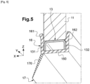
- the connecting member 16 has a U-shaped cross-section, comprising a core 160, arranged so as to come extend opposite the bottom face 130 of the radiator 11, over the entire width thereof, and two branches 161, 162.
- each branch 161, 162 of the U-shaped profile forming the connection member 16 is adapted to engage on a respective fallen edge 131, 132 of the lower cheek 13 of the radiator 11. More precisely, according to the exemplary embodiment of the figure 5 , the internal faces facing each other of the respective branches 161, 162 of the U-shaped profile are adapted to cooperate by friction (or tight assembly) with the external walls of the respective flanged edges 131, 132 of the lower cheek of the radiator. In this arrangement, the sealing device completely frames from the outside the two flanged edges of the lower cheek of the radiator.
- each branch 161, 162 of the U-shaped profile comprises a clipping groove, respectively 1610, 1620, in which a respective fallen edge of the pair of opposite fallen edges 131, 132 of the lower cheek 13 of the radiator 11 is clipped.
- Each branch 161, 162 of the U-shaped profile is for this purpose constituted by two walls, external and internal, facing each other and distant from each other, respectively 1611, 1612 and 1621, 1622, and each clipping groove 1610, 1620 extends between these two facing walls distant from each other of the respective branches of the U-shaped profile.
- the branches 161, 162 of the U-shaped profile each respectively form a first and a second clipping means with a respective fallen edge 131, 132 of the lower cheek 13 of the radiator 11.
- the clipping grooves 1610, 1620 of the branches of the U-shaped profile therefore form two grooves open upwards, each receiving a fallen edge of the lower cheek of the radiator.
- the clipping grooves 1610, 1620 of each branch of the U-shaped profile have a substantially rectangular profile defined by the respective pairs of external and internal walls 1611, 1612 and 1621, 1622.
- the distance separating said walls opposite the clipping grooves of each branch of the U-shaped profile is adapted to the thickness of the fallen edges of the lower cheek of the radiator, so as to allow these edges to be forcefully received by clipping. fallen into the respective clipping grooves of the branches of the U-shaped profile.
- the depth of the clipping grooves is adapted to the height of the fallen edges of the lower cheek.
- the opposite internal faces of the clipping grooves 1610, 1620 cooperate by friction (or tight assembly) respectively with the internal and external walls of each respective fallen edge. In this arrangement, the sealing device completely frames from the outside the two fallen edges of the lower cheek of the radiator.
- the inner faces of the clipping grooves for example the inner faces of the respective inner walls 1612, 1622 of the clipping grooves 1610, 1620, preferably comprise flexible ribs 1613, 1623, projecting towards the inside of the groove and intended to deform elastically during the insertion of the respective flanged edges of the lower cheek, thus ensuring a tight fit of the flanged edges in the respective clipping grooves.
- These ribs also make it difficult to remove the flanged edges from their respective clipping groove.
- the clipping grooves of each branch of the U-shaped profile have a constant profile over the entire length of the seal.
- the clipping grooves of each branch of the U preferably have an asymmetrical profile.
- the respective external walls 1611 and 1621 of the branches of the U-shaped profile are higher than the respective internal walls 1612 and 1622. More precisely, the respective external walls 1611 and 1621 of the branches of the U-shaped profile are dimensioned so as to come to bear against a bearing surface of the respective transverse faces of the radiator extending above the lower cheek when the flanged edges of the lower cheek are clipped into the clipping grooves. The holding of the seal under the radiator is thus further improved.
- the relatively more flexible portion of the seal of the invention may consist of a single sealing lip 170. As illustrated for example in the figure 5 , this single sealing lip 170 extends from one of the branches of the U-profile.
- the relatively more flexible portion of the seal of the invention comprises at least one sealing lip 170 extending from each branch of the U-shaped profile.
- the respective sealing lips 170 of the relatively more flexible portion 17 of the seal 15 extend from the free end of the respective branches 161, 162 of the U-shaped profile, opposite the web 160 of the U relative to the clipping grooves 1610, 1620 of the respective branches of the U-shaped profile.
- the web 160 of the U-shaped profile forms a heel which comes into contact with the bottom face 130 of the radiator extending between the two flanged edges 131, 132.
- the respective sealing lips 170 of the relatively more flexible portion 17 of the seal 15 extend from the foot of the respective branches 161, 162 of the U-shaped profile, opposite the clipping grooves 1610, 1620 of the respective branches of the U-shaped profile relative to the web 160 of the U-shaped profile.
- the flanged edges 131, 132 of the lower cheek 13 are clipped with a tight fit in the clipping grooves 1610, 1620 of the respective branches 161, 162 of the U-shaped profile and the external walls 1611 and 1621 of the respective branches of the U-shaped profile come to bear against the respective transverse faces on either side of the radiator, i.e. against the respective external walls of the edges fallen from the lower cheek 13 of the radiator, extending to above the lower cheek 13, while the core 160 of the U-shaped profile extends substantially at a distance from the bottom face 130 of the radiator 11.
- the sealing device completely surrounds the two fallen edges of the lower cheek of the radiator from the outside.
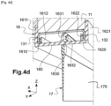
- the core 160 of the U-shaped profile may comprise an intermediate clipping groove 1630 arranged between the clipping grooves 1610, 1620 of the respective branches 161, 162 of the U-shaped profile.
- This intermediate clipping groove 1630 is delimited by two internal walls 1631 and 1632 which each extend respectively opposite the internal wall of the clipping grooves 1610 and 1620 of the respective branches of the U-shaped profile.
- the seal 15 will be able to adapt to different thicknesses of radiator, respectively a first relatively greater thickness by using together the clipping grooves 1610, 1620 of the respective branches 161, 162 of the U-shaped profile, as illustrated in FIG. Figure 4b , and a second relatively smaller thickness by using together the intermediate clipping groove 1630 with for example the clipping groove 1610 of the branch 161 of the U-profile, as illustrated in figure 4c .
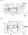
- the respective sealing lips 170 of the relatively more flexible part 17 of the seal 15 which are formed under the U-shaped profile of the relatively more rigid part 16 of the seal, are two in number and extend from each respective branch of the U-shaped profile, in this case from the foot of each branch of the U-shaped profile in the example of the Figure 4a , along two parallel transverse vertical planes, or along planes substantially orthogonal to the plane of the core of the U-shaped profile.
- the sealing gasket may comprise a single sealing lip 170, arranged for example under the intermediate clipping groove 1630 arranged between the clipping grooves 1610, 1620 of the respective branches 161, 162 of the U-profile.
- the respective sealing lips 170 formed at the respective branches of the U and in this case at their free end according to the example of the Figure 3a can also extend under the U-profile along respective planes diverging from the plane of the U-shaped web.
- the respective sealing lips 170 may extend from each respective branch of the U-shaped profile, joining together to form a single bead under the U-shaped profile whose concavity is oriented towards the web of the U.
- Such a configuration of the relatively softer portion of the seal into a single-piece bead under the U-shaped profile is particularly advantageous for enabling the seal to adapt to difficult docking areas while maintaining the sealing function.
- sealing lips 170 which extend from at least one branch and, in this case following the example of the figure 3 , from each branch 161, 162 of the U-profile and this, according to different respective orientation planes, depending on the sealing requirements in the area.
Landscapes
- Engineering & Computer Science (AREA)
- Chemical & Material Sciences (AREA)
- Combustion & Propulsion (AREA)
- Transportation (AREA)
- Mechanical Engineering (AREA)
- Cooling, Air Intake And Gas Exhaust, And Fuel Tank Arrangements In Propulsion Units (AREA)
- Seal Device For Vehicle (AREA)
Claims (12)
- Dichtungsvorrichtung, die geeignet ist, einen Luftdurchgang unter einem Kühler (11) eines Kraftfahrzeugs zu verschließen, mit einer Dichtung (15) aus zwei Teilen, nämlich einem relativ steiferen Teil (16) und einem relativ weicheren Teil (17), wobei der relativ steifere Teil aus einem Profil gebildet wird, das so beschaffen ist, dass es durch Einklipsen mit einer unteren Wange (13) des Kühlers zusammenwirkt, die aus einer Platte (130) besteht, die den Boden des Kühlers bildet und ein Paar von gegenüberliegenden Fallkanten (131, 132) aufweist, die sich im Wesentlichen vertikal unter dem Boden (130) des Kühlers erstrecken und der relativ weichere Teil mindestens eine flexible Dichtlippe (170) aufweist, die so beschaffen ist, dass sie sich unter dem Profil gegenüber der unteren Wange erstreckt, wenn die Dichtung unter dem Kühler montiert ist, dadurch gekennzeichnet, dass das Profil einen U-förmigen Querschnitt aufweist, wobei jeder Schenkel (161, 162) so beschaffen ist, dass er mit einer jeweiligen Fallkante des Paars von gegenüberliegenden Fallkanten der unteren Wange (13) des Kühlers in Eingriff kommt, wobei die Schenkel des U-Profils so beschaffen sind, dass sie mit mindestens einer Außenwand einer jeweiligen Fallkante des Paars von gegenüberliegenden Fallkanten der unteren Wange (13) des Kühlers reibschlüssig zusammenwirken, während der Steg (160) des U-Profils dazu bestimmt ist, sich gegenüber einer Bodenfläche (130) des Kühlers zu erstrecken, die sich zwischen dem Paar von Fallkanten erstreckt.
- Vorrichtung nach Anspruch 1, dadurch gekennzeichnet, dass jeder Schenkel (161, 162) des U-Profils eine Einklipsnut (1610, 1620) aufweist, in die eine jeweilige Fallkante (131, 132) des Paares von gegenüberliegenden Fallkanten der unteren Wange des Kühlers eingeklipst werden soll.
- Vorrichtung nach Anspruch 1 oder 2, dadurch gekennzeichnet, dass sie mindestens eine Dichtlippe (170) aufweist, die sich von mindestens einem Schenkel des U-Profils aus erstreckt.
- Vorrichtung nach einem der Ansprüche 1 bis 3, dadurch gekennzeichnet, dass sie mindestens eine Dichtlippe (170) aufweist, die an jedem Schenkel (161, 162) des U-Profils ausgebildet ist, wobei sich die Dichtlippen in Ebenen erstrecken, die im Wesentlichen orthogonal zur Ebene des Stegs (160) des U-Profils sind.
- Vorrichtung nach einem der Ansprüche 1 bis 3, dadurch gekennzeichnet, dass sie mindestens eine Dichtlippe (170) aufweist, die an jedem Schenkel (161, 162) des U-Profils ausgebildet ist, wobei sich die Dichtlippen entlang der jeweiligen Ebenen erstrecken, die von der Ebene des Stegs (160) des U-Profils divergieren.
- Vorrichtung nach einem der Ansprüche 1 bis 3, dadurch gekennzeichnet, dass sie mindestens eine Dichtlippe (170) aufweist, die an jedem Schenkel (161, 162) des U-Profils ausgebildet ist, wobei die Dichtlippen so zusammenlaufen, dass sie einen einzigen Wulst bilden, dessen Konkavität zum Steg des U-Profils hin gerichtet ist.
- Vorrichtung nach einem der Ansprüche 1 bis 3, dadurch gekennzeichnet, dass sie mindestens zwei Dichtlippen (170) aufweist, die sich von mindestens einem Schenkel (161, 162) des U-Profils entlang unterschiedlicher jeweiliger Ausrichtungsebenen erstrecken.
- Vorrichtung nach einem der vorhergehenden Ansprüche, dadurch gekennzeichnet, dass sich jede Dichtlippe (170) von einem freien Ende eines jeweiligen Schenkels (161, 162) des U-Profils gegenüber dem Steg (160) des U-Profils in Bezug auf die jeweiligen Schenkel des U-Profils erstreckt.
- Vorrichtung nach Anspruch 8, dadurch gekennzeichnet, dass der Steg (160) des U-Profils einen Absatz bildet, der dazu bestimmt ist, an der Bodenfläche (130) des Kühlers anzuliegen, die sich zwischen den beiden Fallkanten (131, 132) des Paars von gegenüberliegenden Fallkanten der unteren Wange (13) des Kühlers erstreckt.
- Vorrichtung nach einem der Ansprüche 1 bis 7, dadurch gekennzeichnet, dass sich jede Dichtlippe (170) von einem Fuß eines jeweiligen Schenkels (161, 162) des U-Profils aus gegenüber den jeweiligen Schenkeln (161, 162) des Us in Bezug auf den Steg (160) des U-Profils erstreckt.
- Vorrichtung nach Anspruch 2 und 10, dadurch gekennzeichnet, dass der Steg (160) des U-Profils eine Zwischen-Einklipsnut (1630) aufweist, die zwischen den Einklipsnuten (1610, 1620) der jeweiligen Schenkel (161, 162) des U-Profils angeordnet ist.
- Kraftfahrzeug mit einem Kühlerträgerquerträger (14), der sich quer über einen Motorraum des Fahrzeugs erstreckt, und einem Wärmetauschermodul (10) mit einem Kühler (11), der auf dem Kühlerträgerquerträger (14) positioniert ist, einer mit dem Kühler gekoppelten unteren Wange (13) mit einem Paar gegenüberliegender Fallkanten und einer Dichtungsvorrichtung nach einem der vorhergehenden Ansprüche, wobei die mindestens eine Dichtlippe (170) so beschaffen ist, dass sie die Luftdurchgänge zwischen dem Boden des Kühlers und dem Kühlerträgerquerträger kontinuierlich verschließt.
Applications Claiming Priority (2)
| Application Number | Priority Date | Filing Date | Title |
|---|---|---|---|
| FR1914071A FR3104076B1 (fr) | 2019-12-10 | 2019-12-10 | Joint d’étanchéité sous radiateur |
| PCT/EP2020/082652 WO2021115752A1 (fr) | 2019-12-10 | 2020-11-19 | Joint d'étanchéité sous radiateur |
Publications (2)
| Publication Number | Publication Date |
|---|---|
| EP4072882A1 EP4072882A1 (de) | 2022-10-19 |
| EP4072882B1 true EP4072882B1 (de) | 2025-01-01 |
Family
ID=69811194
Family Applications (1)
| Application Number | Title | Priority Date | Filing Date |
|---|---|---|---|
| EP20807041.7A Active EP4072882B1 (de) | 2019-12-10 | 2020-11-19 | Dichtung unter einem kühler |
Country Status (3)
| Country | Link |
|---|---|
| EP (1) | EP4072882B1 (de) |
| FR (1) | FR3104076B1 (de) |
| WO (1) | WO2021115752A1 (de) |
Families Citing this family (1)
| Publication number | Priority date | Publication date | Assignee | Title |
|---|---|---|---|---|
| EP4556838A1 (de) * | 2023-11-15 | 2025-05-21 | Valeo Systemes Thermiques | Dichtung für einen kondensator |
Citations (2)
| Publication number | Priority date | Publication date | Assignee | Title |
|---|---|---|---|---|
| EP0950555B1 (de) * | 1998-01-31 | 2001-08-08 | Ford Global Technologies, Inc., A subsidiary of Ford Motor Company | Dichtlippe zwischen Kraftfahrzeugkühler und Luftleitprofil |
| EP3315890B1 (de) * | 2016-10-27 | 2020-01-29 | Valeo Autosystemy SP. Z.O.O. | Luftabdichtung für fahrzeugwärmetauscher |
Family Cites Families (1)
| Publication number | Priority date | Publication date | Assignee | Title |
|---|---|---|---|---|
| US8408344B2 (en) | 2010-09-01 | 2013-04-02 | Toyota Motor Engineering & Manufacturing North America, Inc. | Sealing members for radiator assemblies and radiator assemblies comprising the same |
-
2019
- 2019-12-10 FR FR1914071A patent/FR3104076B1/fr active Active
-
2020
- 2020-11-19 WO PCT/EP2020/082652 patent/WO2021115752A1/fr not_active Ceased
- 2020-11-19 EP EP20807041.7A patent/EP4072882B1/de active Active
Patent Citations (2)
| Publication number | Priority date | Publication date | Assignee | Title |
|---|---|---|---|---|
| EP0950555B1 (de) * | 1998-01-31 | 2001-08-08 | Ford Global Technologies, Inc., A subsidiary of Ford Motor Company | Dichtlippe zwischen Kraftfahrzeugkühler und Luftleitprofil |
| EP3315890B1 (de) * | 2016-10-27 | 2020-01-29 | Valeo Autosystemy SP. Z.O.O. | Luftabdichtung für fahrzeugwärmetauscher |
Also Published As
| Publication number | Publication date |
|---|---|
| WO2021115752A1 (fr) | 2021-06-17 |
| FR3104076B1 (fr) | 2024-05-31 |
| EP4072882A1 (de) | 2022-10-19 |
| FR3104076A1 (fr) | 2021-06-11 |
Similar Documents
| Publication | Publication Date | Title |
|---|---|---|
| EP4072883A1 (de) | Kühlmodul für ein kraftfahrzeug | |
| FR2965219A3 (fr) | Dispositif de climatisation d'un vehicule automobile | |
| EP4072882B1 (de) | Dichtung unter einem kühler | |
| FR2935474A1 (fr) | Dispositif de fixation pour un echangeur de chaleur a ailettes, notamment pour vehicules automobiles | |
| EP3463959B1 (de) | Lager-verschlusselement für lufteinlassregelsystem und frontendmodul für kraftfahrzeug | |
| EP3857156B1 (de) | Wärmetauscherplatte mit optimierter öffnung | |
| EP1162121B1 (de) | Vorrichtung zum Befestigen eines Faltenbalges und Verfahren zu dessen Verwendung | |
| EP2265456B1 (de) | Vorrichtung zur ablenkung von luft von einer fahrzeugvorderflächenstruktur | |
| FR3097182A1 (fr) | Capot pour un système d’essuyage comprenant une aile. | |
| FR3130720A1 (fr) | Embout d’extrémité et balai d’essuie-glace pour véhicule automobile | |
| FR2812909A1 (fr) | Dispositif d'amortissement et de fixation etanche d'un carter d'huile | |
| FR3120842A1 (fr) | véhicule doté d’une grille d’auvent en deux parties | |
| FR2745046A1 (fr) | Profile destine a etre fixe sur une structure fixe, en particulier a l'interieur de l'habitacle d'un vehicule automobile | |
| FR3111332A1 (fr) | Mât d’aéronef comportant au moins un joint d’étanchéité intercalé entre une structure fixe et un panneau démontable d’un carénage | |
| WO1997025217A1 (fr) | JOINT D'ETANCHEITE POUR VEHICULES AUTOMOBILES AVEC UN FOND EN $g(V) | |
| FR3090507A1 (fr) | Système thermique d’un véhicule automobile | |
| EP3366531A1 (de) | Anpassbare endkappe für ein wischblatt | |
| FR3142400A1 (fr) | Vehicule automobile comprenant un joint d’etancheite entre des fixations avec deux nervures fourchues, batterie et procede sur la base d’un tel vehicule | |
| WO2020099808A1 (fr) | Tube pour échangeur de chaleur | |
| FR3134784A1 (fr) | Véhicule automobile comprenant un joint entre un volet et une ouverture avant. | |
| FR3130721A1 (fr) | Embout d’extrémité et balai d’essuie-glace pour véhicule automobile | |
| FR3134042A1 (fr) | Guide d’air pour dispositif de refroidissement de véhicule automobile | |
| WO2006054018A1 (fr) | Fixation tuyau d'air en plastique dans une forme elliptique realisee dans la facade avant du vehicule | |
| FR3119135A1 (fr) | Déflecteur monobloc de système d’essuyage de véhicule | |
| FR3154044A1 (fr) | Boîtier d’un module d'entrée d'air piloté pour une face avant d’un véhicule automobile |
Legal Events
| Date | Code | Title | Description |
|---|---|---|---|
| STAA | Information on the status of an ep patent application or granted ep patent |
Free format text: STATUS: UNKNOWN |
|
| STAA | Information on the status of an ep patent application or granted ep patent |
Free format text: STATUS: THE INTERNATIONAL PUBLICATION HAS BEEN MADE |
|
| PUAI | Public reference made under article 153(3) epc to a published international application that has entered the european phase |
Free format text: ORIGINAL CODE: 0009012 |
|
| STAA | Information on the status of an ep patent application or granted ep patent |
Free format text: STATUS: REQUEST FOR EXAMINATION WAS MADE |
|
| 17P | Request for examination filed |
Effective date: 20220708 |
|
| AK | Designated contracting states |
Kind code of ref document: A1 Designated state(s): AL AT BE BG CH CY CZ DE DK EE ES FI FR GB GR HR HU IE IS IT LI LT LU LV MC MK MT NL NO PL PT RO RS SE SI SK SM TR |
|
| DAV | Request for validation of the european patent (deleted) | ||
| DAX | Request for extension of the european patent (deleted) | ||
| P01 | Opt-out of the competence of the unified patent court (upc) registered |
Effective date: 20230608 |
|
| RAP1 | Party data changed (applicant data changed or rights of an application transferred) |
Owner name: AMPERE SAS |
|
| GRAP | Despatch of communication of intention to grant a patent |
Free format text: ORIGINAL CODE: EPIDOSNIGR1 |
|
| STAA | Information on the status of an ep patent application or granted ep patent |
Free format text: STATUS: GRANT OF PATENT IS INTENDED |
|
| INTG | Intention to grant announced |
Effective date: 20240618 |
|
| RIN1 | Information on inventor provided before grant (corrected) |
Inventor name: SOLTOIAN, SERGHEI Inventor name: BUI, JOSEPH |
|
| GRAS | Grant fee paid |
Free format text: ORIGINAL CODE: EPIDOSNIGR3 |
|
| GRAA | (expected) grant |
Free format text: ORIGINAL CODE: 0009210 |
|
| STAA | Information on the status of an ep patent application or granted ep patent |
Free format text: STATUS: THE PATENT HAS BEEN GRANTED |
|
| AK | Designated contracting states |
Kind code of ref document: B1 Designated state(s): AL AT BE BG CH CY CZ DE DK EE ES FI FR GB GR HR HU IE IS IT LI LT LU LV MC MK MT NL NO PL PT RO RS SE SI SK SM TR |
|
| REG | Reference to a national code |
Ref country code: GB Ref legal event code: FG4D Free format text: NOT ENGLISH |
|
| REG | Reference to a national code |
Ref country code: CH Ref legal event code: EP |
|
| REG | Reference to a national code |
Ref country code: DE Ref legal event code: R096 Ref document number: 602020044151 Country of ref document: DE |
|
| REG | Reference to a national code |
Ref country code: IE Ref legal event code: FG4D Free format text: LANGUAGE OF EP DOCUMENT: FRENCH |
|
| REG | Reference to a national code |
Ref country code: LT Ref legal event code: MG9D |
|
| REG | Reference to a national code |
Ref country code: NL Ref legal event code: MP Effective date: 20250101 |
|
| REG | Reference to a national code |
Ref country code: AT Ref legal event code: MK05 Ref document number: 1755909 Country of ref document: AT Kind code of ref document: T Effective date: 20250101 |
|
| PG25 | Lapsed in a contracting state [announced via postgrant information from national office to epo] |
Ref country code: NL Free format text: LAPSE BECAUSE OF FAILURE TO SUBMIT A TRANSLATION OF THE DESCRIPTION OR TO PAY THE FEE WITHIN THE PRESCRIBED TIME-LIMIT Effective date: 20250101 |
|
| PG25 | Lapsed in a contracting state [announced via postgrant information from national office to epo] |
Ref country code: FI Free format text: LAPSE BECAUSE OF FAILURE TO SUBMIT A TRANSLATION OF THE DESCRIPTION OR TO PAY THE FEE WITHIN THE PRESCRIBED TIME-LIMIT Effective date: 20250101 |
|
| PG25 | Lapsed in a contracting state [announced via postgrant information from national office to epo] |
Ref country code: PL Free format text: LAPSE BECAUSE OF FAILURE TO SUBMIT A TRANSLATION OF THE DESCRIPTION OR TO PAY THE FEE WITHIN THE PRESCRIBED TIME-LIMIT Effective date: 20250101 |
|
| PG25 | Lapsed in a contracting state [announced via postgrant information from national office to epo] |
Ref country code: ES Free format text: LAPSE BECAUSE OF FAILURE TO SUBMIT A TRANSLATION OF THE DESCRIPTION OR TO PAY THE FEE WITHIN THE PRESCRIBED TIME-LIMIT Effective date: 20250101 |
|
| PG25 | Lapsed in a contracting state [announced via postgrant information from national office to epo] |
Ref country code: NO Free format text: LAPSE BECAUSE OF FAILURE TO SUBMIT A TRANSLATION OF THE DESCRIPTION OR TO PAY THE FEE WITHIN THE PRESCRIBED TIME-LIMIT Effective date: 20250401 Ref country code: IS Free format text: LAPSE BECAUSE OF FAILURE TO SUBMIT A TRANSLATION OF THE DESCRIPTION OR TO PAY THE FEE WITHIN THE PRESCRIBED TIME-LIMIT Effective date: 20250501 |
|
| PG25 | Lapsed in a contracting state [announced via postgrant information from national office to epo] |
Ref country code: HR Free format text: LAPSE BECAUSE OF FAILURE TO SUBMIT A TRANSLATION OF THE DESCRIPTION OR TO PAY THE FEE WITHIN THE PRESCRIBED TIME-LIMIT Effective date: 20250101 |
|
| PG25 | Lapsed in a contracting state [announced via postgrant information from national office to epo] |
Ref country code: LV Free format text: LAPSE BECAUSE OF FAILURE TO SUBMIT A TRANSLATION OF THE DESCRIPTION OR TO PAY THE FEE WITHIN THE PRESCRIBED TIME-LIMIT Effective date: 20250101 Ref country code: PT Free format text: LAPSE BECAUSE OF FAILURE TO SUBMIT A TRANSLATION OF THE DESCRIPTION OR TO PAY THE FEE WITHIN THE PRESCRIBED TIME-LIMIT Effective date: 20250502 |
|
| PG25 | Lapsed in a contracting state [announced via postgrant information from national office to epo] |
Ref country code: BG Free format text: LAPSE BECAUSE OF FAILURE TO SUBMIT A TRANSLATION OF THE DESCRIPTION OR TO PAY THE FEE WITHIN THE PRESCRIBED TIME-LIMIT Effective date: 20250101 Ref country code: GR Free format text: LAPSE BECAUSE OF FAILURE TO SUBMIT A TRANSLATION OF THE DESCRIPTION OR TO PAY THE FEE WITHIN THE PRESCRIBED TIME-LIMIT Effective date: 20250402 |
|
| PG25 | Lapsed in a contracting state [announced via postgrant information from national office to epo] |
Ref country code: AT Free format text: LAPSE BECAUSE OF FAILURE TO SUBMIT A TRANSLATION OF THE DESCRIPTION OR TO PAY THE FEE WITHIN THE PRESCRIBED TIME-LIMIT Effective date: 20250101 |
|
| PG25 | Lapsed in a contracting state [announced via postgrant information from national office to epo] |
Ref country code: CZ Free format text: LAPSE BECAUSE OF FAILURE TO SUBMIT A TRANSLATION OF THE DESCRIPTION OR TO PAY THE FEE WITHIN THE PRESCRIBED TIME-LIMIT Effective date: 20250101 |
|
| PG25 | Lapsed in a contracting state [announced via postgrant information from national office to epo] |
Ref country code: SE Free format text: LAPSE BECAUSE OF FAILURE TO SUBMIT A TRANSLATION OF THE DESCRIPTION OR TO PAY THE FEE WITHIN THE PRESCRIBED TIME-LIMIT Effective date: 20250101 |
|
| REG | Reference to a national code |
Ref country code: DE Ref legal event code: R097 Ref document number: 602020044151 Country of ref document: DE |
|
| PG25 | Lapsed in a contracting state [announced via postgrant information from national office to epo] |
Ref country code: SM Free format text: LAPSE BECAUSE OF FAILURE TO SUBMIT A TRANSLATION OF THE DESCRIPTION OR TO PAY THE FEE WITHIN THE PRESCRIBED TIME-LIMIT Effective date: 20250101 |
|
| PG25 | Lapsed in a contracting state [announced via postgrant information from national office to epo] |
Ref country code: DK Free format text: LAPSE BECAUSE OF FAILURE TO SUBMIT A TRANSLATION OF THE DESCRIPTION OR TO PAY THE FEE WITHIN THE PRESCRIBED TIME-LIMIT Effective date: 20250101 |
|
| PG25 | Lapsed in a contracting state [announced via postgrant information from national office to epo] |
Ref country code: IT Free format text: LAPSE BECAUSE OF FAILURE TO SUBMIT A TRANSLATION OF THE DESCRIPTION OR TO PAY THE FEE WITHIN THE PRESCRIBED TIME-LIMIT Effective date: 20250101 |
|
| PG25 | Lapsed in a contracting state [announced via postgrant information from national office to epo] |
Ref country code: EE Free format text: LAPSE BECAUSE OF FAILURE TO SUBMIT A TRANSLATION OF THE DESCRIPTION OR TO PAY THE FEE WITHIN THE PRESCRIBED TIME-LIMIT Effective date: 20250101 |
|
| PG25 | Lapsed in a contracting state [announced via postgrant information from national office to epo] |
Ref country code: RO Free format text: LAPSE BECAUSE OF FAILURE TO SUBMIT A TRANSLATION OF THE DESCRIPTION OR TO PAY THE FEE WITHIN THE PRESCRIBED TIME-LIMIT Effective date: 20250101 |
|
| PG25 | Lapsed in a contracting state [announced via postgrant information from national office to epo] |
Ref country code: SK Free format text: LAPSE BECAUSE OF FAILURE TO SUBMIT A TRANSLATION OF THE DESCRIPTION OR TO PAY THE FEE WITHIN THE PRESCRIBED TIME-LIMIT Effective date: 20250101 |
|
| PLBE | No opposition filed within time limit |
Free format text: ORIGINAL CODE: 0009261 |
|
| STAA | Information on the status of an ep patent application or granted ep patent |
Free format text: STATUS: NO OPPOSITION FILED WITHIN TIME LIMIT |
|
| 26N | No opposition filed |
Effective date: 20251002 |
|
| PGFP | Annual fee paid to national office [announced via postgrant information from national office to epo] |
Ref country code: DE Payment date: 20251119 Year of fee payment: 6 |
|
| PGFP | Annual fee paid to national office [announced via postgrant information from national office to epo] |
Ref country code: GB Payment date: 20251121 Year of fee payment: 6 |
|
| PGFP | Annual fee paid to national office [announced via postgrant information from national office to epo] |
Ref country code: FR Payment date: 20251126 Year of fee payment: 6 |