EP4072736B1 - Flexible painting plant - Google Patents
Flexible painting plant Download PDFInfo
- Publication number
- EP4072736B1 EP4072736B1 EP20821419.7A EP20821419A EP4072736B1 EP 4072736 B1 EP4072736 B1 EP 4072736B1 EP 20821419 A EP20821419 A EP 20821419A EP 4072736 B1 EP4072736 B1 EP 4072736B1
- Authority
- EP
- European Patent Office
- Prior art keywords
- cartridges
- painting
- magazine
- paint
- station
- Prior art date
- Legal status (The legal status is an assumption and is not a legal conclusion. Google has not performed a legal analysis and makes no representation as to the accuracy of the status listed.)
- Active
Links
Images

Classifications
-
- B—PERFORMING OPERATIONS; TRANSPORTING
- B05—SPRAYING OR ATOMISING IN GENERAL; APPLYING FLUENT MATERIALS TO SURFACES, IN GENERAL
- B05B—SPRAYING APPARATUS; ATOMISING APPARATUS; NOZZLES
- B05B12/00—Arrangements for controlling delivery; Arrangements for controlling the spray area
- B05B12/14—Arrangements for controlling delivery; Arrangements for controlling the spray area for supplying a selected one of a plurality of liquids or other fluent materials or several in selected proportions to a spray apparatus, e.g. to a single spray outlet
- B05B12/1463—Arrangements for controlling delivery; Arrangements for controlling the spray area for supplying a selected one of a plurality of liquids or other fluent materials or several in selected proportions to a spray apparatus, e.g. to a single spray outlet separate containers for different materials to be sprayed being moved from a first location, e.g. a filling station, where they are fluidically disconnected from the spraying apparatus, to a second location, generally close to the spraying apparatus, where they are fluidically connected to the latter
-
- B—PERFORMING OPERATIONS; TRANSPORTING
- B05—SPRAYING OR ATOMISING IN GENERAL; APPLYING FLUENT MATERIALS TO SURFACES, IN GENERAL
- B05B—SPRAYING APPARATUS; ATOMISING APPARATUS; NOZZLES
- B05B13/00—Machines or plants for applying liquids or other fluent materials to surfaces of objects or other work by spraying, not covered by groups B05B1/00 - B05B11/00
- B05B13/02—Means for supporting work; Arrangement or mounting of spray heads; Adaptation or arrangement of means for feeding work
- B05B13/04—Means for supporting work; Arrangement or mounting of spray heads; Adaptation or arrangement of means for feeding work the spray heads being moved during spraying operation
- B05B13/0447—Installation or apparatus for applying liquid or other fluent material to conveyed separate articles
- B05B13/0452—Installation or apparatus for applying liquid or other fluent material to conveyed separate articles the objects being vehicle components, e.g. vehicle bodies
-
- B—PERFORMING OPERATIONS; TRANSPORTING
- B05—SPRAYING OR ATOMISING IN GENERAL; APPLYING FLUENT MATERIALS TO SURFACES, IN GENERAL
- B05B—SPRAYING APPARATUS; ATOMISING APPARATUS; NOZZLES
- B05B15/00—Details of spraying plant or spraying apparatus not otherwise provided for; Accessories
- B05B15/50—Arrangements for cleaning; Arrangements for preventing deposits, drying-out or blockage; Arrangements for detecting improper discharge caused by the presence of foreign matter
- B05B15/55—Arrangements for cleaning; Arrangements for preventing deposits, drying-out or blockage; Arrangements for detecting improper discharge caused by the presence of foreign matter using cleaning fluids
-
- B—PERFORMING OPERATIONS; TRANSPORTING
- B65—CONVEYING; PACKING; STORING; HANDLING THIN OR FILAMENTARY MATERIAL
- B65G—TRANSPORT OR STORAGE DEVICES, e.g. CONVEYORS FOR LOADING OR TIPPING, SHOP CONVEYOR SYSTEMS OR PNEUMATIC TUBE CONVEYORS
- B65G51/00—Conveying articles through pipes or tubes by fluid flow or pressure; Conveying articles over a flat surface, e.g. the base of a trough, by jets located in the surface
- B65G51/04—Conveying the articles in carriers having a cross-section approximating that of the pipe or tube; Tube mail systems
Definitions
- the present invention relates to an innovative painting plant.
- colour centre In plants of a certain size the painting system of a booth (or of several booths) is connected to a special centralized paint source, often called a "colour centre". Usually this "colour centre", which contains large paint containers, is arranged far from the booths (for example also so as to be able to serve several booths at the same time) and is connected to the painting system by means of long ducts for feeding the paint.
- a first problem of such plants is that of avoiding drying or a variation in density of the paint inside the long feed ducts, in particular owing to plant stoppage times (for example so that maintenance of the booths may be carried out).
- the minimum quantity of paint of a particular colour which can be managed by the plant is determined by the quantity of paint which is needed to fill the entire plant. This quantity may be on occasions excessive and may result in a not indifferent amount of waste paint at the end of painting.
- the paint containers of a colour centre of the known type generally contain at least 20-25 litres and therefore are heavy and difficult to manage.
- One of the conveyor systems can be for example a pneumatic system that sends the containers through ducts.
- EP1566221 discloses a coating robot provided with an exchangeable cartridge storing paint therein.
- WO97/34707 discloses a plant having a rotatable magazine for a multitude of interchangeable containers for a coating machine which containers are filled at a location separated from the coating machine and are removed from the magazine at a discharge point and supplied to the coating machine and, after use, are again returned to the magazine.
- EP0895485 discloses a plant for coating objects in which cartridge sorting and storing rack have a plurality of cartridges.
- Conveyor means consists of a ring-shaped, tubular system in which full cartridges are conveyed to a docking station and applicator and back, so that a circular circuit has to be provided for the cartridges.
- the general object of the present invention is to overcome the problems of the prior art mentioned above, by providing a flexible painting plant with more rapid and effective management of the colours and internal cleaning of the plant.
- the idea which has occurred is to provide a method for feeding paint to painting systems inside painting booths as claimed in claim 10.
- the transport system is of the pneumatic type.
- the magazine may be advantageously of the automatic type.
- cartridges containing cleaning liquid may be provided in the magazine so as to send them as an alternative to the cartridges containing paint and use them for cleaning parts of the painting system which have come into contact with the paint.
- the paint cartridges are treated as "consumable" elements that are expelled from the plant once used.
- Figure 1 shows a painting booth according to the invention, denoted generally by 10.
- This plant 10 comprises at least one painting booth 11 in which there are one or more painting systems 12 for painting objects 13, for example in particular motor vehicle bodies or parts thereof, which are conveyed into the booth preferably by means of a sequential transportation line 14 (for example a suitable and known sequential chain, roller or similar conveyor).
- the painting systems 12 may be manual systems with paint application devices (for example paint spray guns) or, for example, may comprise one or more painting robots 12a (advantageously of the anthropomorphic arm type) provided at the end with a suitable paint application device 12b (for example a suitable paint spray gun).
- paint application devices of both the manual and automatically operated type
- paint spray gun any known application device, as will be obvious to the person skilled in the art.
- the booth 11 has advantageously a grille-type floor 15 for allowing the throughflow of the overspray (namely the atomized paint inside the booth which has not become attached to the object to be painted) which is preferably transported by an air flow which is introduced via the ceiling of the booth through an inlet duct 16 and which exits through the grille floor so as to convey the air with the overspray into a known abatement system 17 for eliminating the overspray (for example by means of filters, water jets or other means well-known in the sector) which separates the overspray from the air flow.
- the overspray namely the atomized paint inside the booth which has not become attached to the object to be painted
- a known abatement system 17 for eliminating the overspray (for example by means of filters, water jets or other means well-known in the sector) which separates the overspray from the air flow.
- the air cleaned of the overspray then exits the abatement system 17, for example through one or more ducts 18, and is then introduced into the surrounding environment and/or conveyed back into the booth through the inlet duct 16.
- Special ventilators (not shown) move the air flow.
- the plant 10 comprises an automatic colour magazine 19 which receives inside special seats a plurality of colour cartridges 20 so as to select them and release them on command.
- the magazine may be of the type known per se for receiving, selecting and releasing objects on command.
- a starting station 22 of a system 23 for automatically transporting the cartridges from the starting station to at least one arrival station 33.
- the magazine may for example release and automatically insert into the starting station a selected cartridge 20.
- the magazine may for example be provided with a system 21 for selecting and picking up a cartridge from the plurality of cartridges present in the magazine and insert it directly into the starting station 22 of the system 23 for automatically transporting the cartridges towards the booth 11 as far as a suitable arrival station 33.
- the system for automatically transporting the paint cartridges is realized as a pneumatic transportation system, with each cartridge which is transported along the system (formed by suitable ducts) by means of a suitable air flow.
- the booth 11 has, associated with it, at least one feeding station 24 which feeds the paint from the cartridge to the painting system 12 present in the booth.
- a cartridge transported from the magazine to the arrival station 33 of the automatic transport system 33 may be directly introduced from the arrival station 33 into the feeding station 24.
- the station 24 comprises or advantageously forms also the arrival station 33 of the transport system and is designed to receive a cartridge sent from the magazine through the transport system and connect it automatically to the associated painting system 12 so as to send to it a flow of paint removed from the cartridge.
- a corresponding arrival station 33 and/or feeding station 24 may be associated with each paint spray gun and/or each painting robot.
- the feeding station 24 may be situated in the vicinity of the painting station and a short duct 25 may convey the paint from the cartridge contained inside it to the paint spray gun.
- the feeding station 24 may be situated in the proximity or in the base of the robot 12a such that the mass which the robot must move remains in any case small.
- the station may be located closer to the paint spray gun and the duct 25 may consequently be shorter. If need be, the duct 25 may be eliminated and the cartridge may reach and be engaged inside the paint spray gun which with the cartridge thus forms also the cartridge arrival station 33 and the paint feeding station 24.
- a controlled operation system for cleaning the paint along the section connecting together the cartridge and the gun may be provided in the feeding station 24 or connected thereto.
- This controlled operation system may for example employ a controlled circulation of a suitable cleaning liquid.
- the quantity of cleaning liquid may be kept small since the parts of the plant which come into contact with the paint are few and have small dimensions.
- the cartridge transport system 23 may comprise suitable routing units 26 for sending on command the cartridges 20 from the sending station 22 in the magazine to a selected arrival station 33 of the booths 11.
- a first duct 27 may be provided, said duct leading from the sending station 22 to a routing unit 28 which routes the cartridges into a plurality of ducts 28 each directed towards an arrival station 33.
- routing units may be provided for further routing the cartridges towards a plurality of booths and/or painting systems inside the booths.
- the sending station 22 may produce an adequate flow of air for pushing the cartridges along the ducts of the system and the routing unit 26 may comprise a mobile selector which connects on command the inlet duct 27 alternately to a desired outlet duct 28, so as to allow a cartridge arriving at the routing unit to be introduced without difficulty into the desired duct 28 and thus continue towards the selected arrival station 33.
- the cartridges 20 may have a transverse diameter slightly smaller than the internal diameter of the ducts of the transport system 23 and optionally may also comprise circumferential sealing rings in the proximity of their ends, as substantially known in the case of pneumatic postal systems.
- the cartridges 20 may also have edges of the front and rear ends which are rounded.
- the rear end of the cartridges may have a substantially flat surface so as to obtain a better pneumatic thrust.
- the front end may have a rounded surface for favouring the sliding movement of the cartridge along the ducts also in the case of relatively tight bends along the path.
- the cartridges may have an engaging valve (for example on their front end) for automatic engagement with the paint feeding circuit present in the station 24.
- the cartridges 20 may have a zone which can be perforated and the circuit present in the station 24 for feeding the paint to the painting system 12 may comprise a system for perforating the cartridge so as to introduce a duct for removing the paint through this zone.
- the cartridge may for example be made in the form of a can and have a wall part which is sufficiently weak for it to be perforated by the removal duct, made for example with a suitable pointed shape.
- the perforatable zone may also be made of a material different from the rest of the cartridge.
- this zone may be made with a membrane made of elastomeric material which may be more easily perforated and which, if desired, may also provide a hydraulic seal after extraction of the removal duct from the cartridge, so as to prevent the spread externally of any residual paint which may be left inside the cartridge.
- the stations 24 expel the empty cartridge via a chute 29 which leads into a collection container 30.
- the used cartridges are thus quickly ejected from the plant to be eliminated.
- the plant may be advantageously managed by a control system 31, which is for example made with a suitably programmed electronic controller, known per se, and which may also comprise one or more terminals 32 for displaying information about the plant and the introduction of any commands by an operator.
- a control system 31 which is for example made with a suitably programmed electronic controller, known per se, and which may also comprise one or more terminals 32 for displaying information about the plant and the introduction of any commands by an operator.
- the control system 31 may for example be programmed to send to a desired painting system (for example a particular robot) a cartridge containing the desired colour from among those colours available in the cartridges present in the magazine, detecting also when a cartridge is empty so that another replacement cartridge of the same colour or with a different colour can be sent, as required.
- a desired painting system for example a particular robot
- control system may also control operation of the cleaning system so as to eliminate traces of the previous colour before using the colour of the new cartridge.
- the control system may perform cleaning in a very simple manner, retrieving from the magazine a cleaning cartridge before the cartridge with the new colour and performing withdrawal and emission of the cleaning liquid in the zone where the paint was previously circulating.
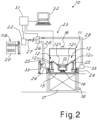
- Figure 2 shows a simplified variant of a plant according to the invention. Parts similar to those shown in Figure 1 are indicated in Figure 2 using the same numbering as in Figure 1 and, except where differently indicated below, for these parts reference may be made to the description provided above.
- the plant 10 according to Figure 2 always comprises at least one painting booth 11 containing one or more automatic or manual painting systems 12 for painting objects 13, for example in particular motor vehicle bodies or parts thereof, which are conveyed into the booth preferably by means of the sequential transportation line 14.
- the booth may have a grille-type floor 15 and an air circulation and filtration system 16, 17, 18 for eliminating the overspray.
- the booths have stations 24 for feeding the paint from the cartridges inserted inside them to the painting devices inside the booths.
- the plant comprises a colour magazine 119 inside which the colour cartridges 20 are stored.
- the starting station 22 of the automatic transport system 23 which transports the cartridges to the arrival stations 33 so that they can be transferred and inserted into the corresponding feeding station 24.
- the transfer of the cartridges from the magazine 119 to the starting station may be performed manually by an operator, who removes a cartridge from the magazine and inserts it into the starting station.
- the choice of the cartridge may for example be indicated to the operator by the control system 31 via a terminal 32.
- the transfer of the cartridges from the arrival station 33 to the feeding station 24 may be performed manually by an operator who removes the cartridge which has arrived at the arrival station 33 and inserts it inside a feeding station 24.
- a new cartridge may be automatically requested by the control system or by an operator at the booth.
- An operator at the magazine may remove from the magazine a cartridge 20 containing a suitable colour, insert it into the starting station 22 and send it via the automatic transport system 23 to the appropriate arrival station 33 from where it may be removed by an operator and inserted into the feeding station of the painting system waiting for the paint, after extraction of the empty cartridge. All of this may be performed in a rapid and easy manner.
- the cartridges may have small dimensions (also only 0.1 to 2 litres) and, if a greater capacity is required in order to paint for a longer period of time using the same colour, it is sufficient to recall in succession the cartridges containing paint of the same colour.
- the cartridges may be made of low-cost recyclable materials and may be of the disposable type or type which can be reused several times by filling them again.
- the cartridges may be made of cardboard, aluminium, plastic, etc.
- the cartridges are used substantially as “consumables” which are sent to the painting system from the warehouse and then once the paint has been consumed, they are ejected directly, as substantially “disposable” elements.
- the magazine whether it be automatic or manual may be easily filled manually by an operator, in view also of the low weight which the single cartridges may have.
- several booths may be fed by several magazines or several magazines may be used in order to supply the cartridges to a single booth or group of booths.
- the magazine may obviously be of any desired size and house any number of cartridges.
- the paints used may be of various types and different methods used to apply them onto the object to be painted.
- the paints may also be in powder form as well as liquid form and may be applied by the guns using pressurized spray nozzles, electrostatic methods, etc.
- a same magazine may contain also cartridges with paints of a different type together with any suitable corresponding different cleaning liquids and the plant may use the different paints and liquids in an in any case rapid and efficient manner, depending on the requirements.
- the painting systems inside the booths may be different from those shown in the drawings.
- the paint spray guns inside the booths may be moved using systems different from those shown.
- robots without anthropomorphic arms may be used or the guns may be simply manually operated by human operators.
- FIG. 1 parts described for the embodiment shown in Figure 1 may also be used for the embodiment shown in Figure 2 .
- an automatic magazine 19 may be used instead of the manual magazine 119 so as to supply automatically the cartridges directly to the starting station 22 or to the operator who must transfer them to the starting station 22.
- arrival stations 33 and feeding stations 24 which are separate and with an operator who transfers the cartridges from one station to the other may also be used, as shown in Figure 2 .
Landscapes
- Details Or Accessories Of Spraying Plant Or Apparatus (AREA)
- Spray Control Apparatus (AREA)
- Application Of Or Painting With Fluid Materials (AREA)
Priority Applications (1)
| Application Number | Priority Date | Filing Date | Title |
|---|---|---|---|
| RS20240610A RS65566B1 (sr) | 2019-12-11 | 2020-12-10 | Fleksibilno postrojenje za farbanje |
Applications Claiming Priority (2)
| Application Number | Priority Date | Filing Date | Title |
|---|---|---|---|
| IT102019000023613A IT201900023613A1 (it) | 2019-12-11 | 2019-12-11 | Impianto flessibile di verniciatura |
| PCT/IB2020/061720 WO2021116951A1 (en) | 2019-12-11 | 2020-12-10 | Flexible painting plant |
Publications (3)
| Publication Number | Publication Date |
|---|---|
| EP4072736A1 EP4072736A1 (en) | 2022-10-19 |
| EP4072736C0 EP4072736C0 (en) | 2024-03-27 |
| EP4072736B1 true EP4072736B1 (en) | 2024-03-27 |
Family
ID=70154989
Family Applications (1)
| Application Number | Title | Priority Date | Filing Date |
|---|---|---|---|
| EP20821419.7A Active EP4072736B1 (en) | 2019-12-11 | 2020-12-10 | Flexible painting plant |
Country Status (12)
| Country | Link |
|---|---|
| US (1) | US11857988B2 (es) |
| EP (1) | EP4072736B1 (es) |
| JP (1) | JP2023505103A (es) |
| CN (1) | CN114786822B (es) |
| BR (1) | BR112022010093A2 (es) |
| ES (1) | ES2984530T3 (es) |
| HU (1) | HUE066714T2 (es) |
| IT (1) | IT201900023613A1 (es) |
| MX (1) | MX2022007069A (es) |
| PL (1) | PL4072736T3 (es) |
| RS (1) | RS65566B1 (es) |
| WO (1) | WO2021116951A1 (es) |
Families Citing this family (1)
| Publication number | Priority date | Publication date | Assignee | Title |
|---|---|---|---|---|
| CN116116599B (zh) * | 2022-12-07 | 2025-11-07 | 上海拔山自动化技术有限公司 | 一种汽车喷涂机器人用油漆换色系统及换色方法 |
Family Cites Families (11)
| Publication number | Priority date | Publication date | Assignee | Title |
|---|---|---|---|---|
| DE3437046C2 (de) * | 1984-10-09 | 1987-03-19 | Agfa-Gevaert Ag, 5090 Leverkusen | Vorrichtung zur Entnahme des Films aus einer Filmpatrone |
| FR2638724B1 (fr) * | 1988-11-04 | 1991-01-11 | Bourg Sa Cp | Installation de transport pneumatique et protege d'objets de valeur |
| CA2248928A1 (en) * | 1996-03-18 | 1997-09-25 | Behr Systems, Inc. | Paint system with color change canisters |
| DE19616668A1 (de) | 1996-04-26 | 1997-11-06 | Audi Ag | Beschichtungsanlage zum Beschichten von Gegenständen mit häufig wechselndem Farbmaterial |
| EP1717167A3 (en) * | 1997-05-30 | 2006-11-15 | Hino Jidosha Kogyo Kabushiki Kaisha | Multi-color small amount painting system |
| CA2282595C (en) * | 1998-01-13 | 2004-04-13 | Abb K.K. | Coating method by the use of rotary atomizing head type coating system |
| JP2004008949A (ja) * | 2002-06-07 | 2004-01-15 | Toyota Motor Corp | 塗装方法 |
| JP4473006B2 (ja) * | 2004-02-20 | 2010-06-02 | トヨタ自動車株式会社 | カートリッジ式塗装装置およびそのカートリッジ |
| KR101006421B1 (ko) * | 2007-02-06 | 2011-01-06 | 에이비비 가부시키가이샤 | 도장 장치 |
| EP2110180B1 (en) * | 2007-02-06 | 2011-11-16 | Abb K.K. | Coating system |
| JP7169454B2 (ja) * | 2019-08-09 | 2022-11-10 | アーベーベー・シュバイツ・アーゲー | 塗装機 |
-
2019
- 2019-12-11 IT IT102019000023613A patent/IT201900023613A1/it unknown
-
2020
- 2020-12-10 BR BR112022010093A patent/BR112022010093A2/pt unknown
- 2020-12-10 JP JP2022532009A patent/JP2023505103A/ja active Pending
- 2020-12-10 EP EP20821419.7A patent/EP4072736B1/en active Active
- 2020-12-10 PL PL20821419.7T patent/PL4072736T3/pl unknown
- 2020-12-10 ES ES20821419T patent/ES2984530T3/es active Active
- 2020-12-10 HU HUE20821419A patent/HUE066714T2/hu unknown
- 2020-12-10 CN CN202080085642.XA patent/CN114786822B/zh active Active
- 2020-12-10 RS RS20240610A patent/RS65566B1/sr unknown
- 2020-12-10 US US17/782,250 patent/US11857988B2/en active Active
- 2020-12-10 WO PCT/IB2020/061720 patent/WO2021116951A1/en not_active Ceased
- 2020-12-10 MX MX2022007069A patent/MX2022007069A/es unknown
Also Published As
| Publication number | Publication date |
|---|---|
| US20230010454A1 (en) | 2023-01-12 |
| RS65566B1 (sr) | 2024-06-28 |
| EP4072736C0 (en) | 2024-03-27 |
| HUE066714T2 (hu) | 2024-09-28 |
| CN114786822A (zh) | 2022-07-22 |
| IT201900023613A1 (it) | 2021-06-11 |
| MX2022007069A (es) | 2022-07-11 |
| PL4072736T3 (pl) | 2024-07-22 |
| BR112022010093A2 (pt) | 2022-09-06 |
| ES2984530T3 (es) | 2024-10-29 |
| EP4072736A1 (en) | 2022-10-19 |
| WO2021116951A1 (en) | 2021-06-17 |
| US11857988B2 (en) | 2024-01-02 |
| CN114786822B (zh) | 2024-11-22 |
| JP2023505103A (ja) | 2023-02-08 |
Similar Documents
| Publication | Publication Date | Title |
|---|---|---|
| CN1182923C (zh) | 在喷涂涂层产品的喷涂设备中改换产品的方法和操作台 | |
| US3981320A (en) | Recovery system for spray painting installation with automatic color change | |
| EP0317155A2 (en) | Paint color change system | |
| US9415409B2 (en) | Device for conveying coating powder from a powder container | |
| EP3441147B1 (en) | Powder supplying device for a powder coating installation | |
| US6830414B2 (en) | Canister powder paint delivery apparatus and method | |
| CN1211165C (zh) | 给喷涂器供料的装置和方法以及装有这种装置的喷涂设备 | |
| WO1997034707A1 (en) | Paint system with color change canisters | |
| EP4072736B1 (en) | Flexible painting plant | |
| JP3992752B2 (ja) | スプレイ塗装装置に塗料を供給するためのプラント | |
| RU2823697C1 (ru) | Универсальная окрасочная установка | |
| US6401768B2 (en) | Method and configuration for transporting electrically conductive paint | |
| CN1207104C (zh) | 给喷涂器供料的装置和方法以及装有这种装置的喷涂设备 | |
| US20010047755A1 (en) | Method and configuration for transporting electrically conductive paint | |
| JP2003093931A (ja) | 多色少量塗装システム | |
| JPH11593A (ja) | 多色少量塗装システム | |
| EP3398689B1 (en) | An apparatus for the powder coating of an object and related opeative method | |
| JP2010274248A (ja) | 塗装システム | |
| EP1469948B1 (en) | Device for removing and sucking powders externally of one or more powder-drawing pipes | |
| CN101175575A (zh) | 用于涂料喷涂机的穿梭推动系统 | |
| WO2008070046A2 (en) | Powder coating system | |
| MXPA98007380A (es) | Sistema de pintura con botes de cambio de color |
Legal Events
| Date | Code | Title | Description |
|---|---|---|---|
| STAA | Information on the status of an ep patent application or granted ep patent |
Free format text: STATUS: UNKNOWN |
|
| STAA | Information on the status of an ep patent application or granted ep patent |
Free format text: STATUS: THE INTERNATIONAL PUBLICATION HAS BEEN MADE |
|
| PUAI | Public reference made under article 153(3) epc to a published international application that has entered the european phase |
Free format text: ORIGINAL CODE: 0009012 |
|
| STAA | Information on the status of an ep patent application or granted ep patent |
Free format text: STATUS: REQUEST FOR EXAMINATION WAS MADE |
|
| 17P | Request for examination filed |
Effective date: 20220504 |
|
| AK | Designated contracting states |
Kind code of ref document: A1 Designated state(s): AL AT BE BG CH CY CZ DE DK EE ES FI FR GB GR HR HU IE IS IT LI LT LU LV MC MK MT NL NO PL PT RO RS SE SI SK SM TR |
|
| DAV | Request for validation of the european patent (deleted) | ||
| DAX | Request for extension of the european patent (deleted) | ||
| STAA | Information on the status of an ep patent application or granted ep patent |
Free format text: STATUS: EXAMINATION IS IN PROGRESS |
|
| 17Q | First examination report despatched |
Effective date: 20230530 |
|
| GRAP | Despatch of communication of intention to grant a patent |
Free format text: ORIGINAL CODE: EPIDOSNIGR1 |
|
| STAA | Information on the status of an ep patent application or granted ep patent |
Free format text: STATUS: GRANT OF PATENT IS INTENDED |
|
| INTG | Intention to grant announced |
Effective date: 20240112 |
|
| GRAS | Grant fee paid |
Free format text: ORIGINAL CODE: EPIDOSNIGR3 |
|
| GRAA | (expected) grant |
Free format text: ORIGINAL CODE: 0009210 |
|
| STAA | Information on the status of an ep patent application or granted ep patent |
Free format text: STATUS: THE PATENT HAS BEEN GRANTED |
|
| AK | Designated contracting states |
Kind code of ref document: B1 Designated state(s): AL AT BE BG CH CY CZ DE DK EE ES FI FR GB GR HR HU IE IS IT LI LT LU LV MC MK MT NL NO PL PT RO RS SE SI SK SM TR |
|
| REG | Reference to a national code |
Ref country code: GB Ref legal event code: FG4D |
|
| REG | Reference to a national code |
Ref country code: CH Ref legal event code: EP |
|
| REG | Reference to a national code |
Ref country code: DE Ref legal event code: R096 Ref document number: 602020028065 Country of ref document: DE |
|
| REG | Reference to a national code |
Ref country code: IE Ref legal event code: FG4D |
|
| U01 | Request for unitary effect filed |
Effective date: 20240422 |
|
| U07 | Unitary effect registered |
Designated state(s): AT BE BG DE DK EE FI FR IT LT LU LV MT NL PT SE SI Effective date: 20240429 |
|
| PG25 | Lapsed in a contracting state [announced via postgrant information from national office to epo] |
Ref country code: GR Free format text: LAPSE BECAUSE OF FAILURE TO SUBMIT A TRANSLATION OF THE DESCRIPTION OR TO PAY THE FEE WITHIN THE PRESCRIBED TIME-LIMIT Effective date: 20240628 |
|
| PG25 | Lapsed in a contracting state [announced via postgrant information from national office to epo] |
Ref country code: HR Free format text: LAPSE BECAUSE OF FAILURE TO SUBMIT A TRANSLATION OF THE DESCRIPTION OR TO PAY THE FEE WITHIN THE PRESCRIBED TIME-LIMIT Effective date: 20240327 |
|
| PG25 | Lapsed in a contracting state [announced via postgrant information from national office to epo] |
Ref country code: NO Free format text: LAPSE BECAUSE OF FAILURE TO SUBMIT A TRANSLATION OF THE DESCRIPTION OR TO PAY THE FEE WITHIN THE PRESCRIBED TIME-LIMIT Effective date: 20240627 Ref country code: HR Free format text: LAPSE BECAUSE OF FAILURE TO SUBMIT A TRANSLATION OF THE DESCRIPTION OR TO PAY THE FEE WITHIN THE PRESCRIBED TIME-LIMIT Effective date: 20240327 Ref country code: GR Free format text: LAPSE BECAUSE OF FAILURE TO SUBMIT A TRANSLATION OF THE DESCRIPTION OR TO PAY THE FEE WITHIN THE PRESCRIBED TIME-LIMIT Effective date: 20240628 |
|
| REG | Reference to a national code |
Ref country code: HU Ref legal event code: AG4A Ref document number: E066714 Country of ref document: HU |
|
| PG25 | Lapsed in a contracting state [announced via postgrant information from national office to epo] |
Ref country code: IS Free format text: LAPSE BECAUSE OF FAILURE TO SUBMIT A TRANSLATION OF THE DESCRIPTION OR TO PAY THE FEE WITHIN THE PRESCRIBED TIME-LIMIT Effective date: 20240727 |
|
| PG25 | Lapsed in a contracting state [announced via postgrant information from national office to epo] |
Ref country code: SM Free format text: LAPSE BECAUSE OF FAILURE TO SUBMIT A TRANSLATION OF THE DESCRIPTION OR TO PAY THE FEE WITHIN THE PRESCRIBED TIME-LIMIT Effective date: 20240327 |
|
| REG | Reference to a national code |
Ref country code: ES Ref legal event code: FG2A Ref document number: 2984530 Country of ref document: ES Kind code of ref document: T3 Effective date: 20241029 |
|
| PG25 | Lapsed in a contracting state [announced via postgrant information from national office to epo] |
Ref country code: SM Free format text: LAPSE BECAUSE OF FAILURE TO SUBMIT A TRANSLATION OF THE DESCRIPTION OR TO PAY THE FEE WITHIN THE PRESCRIBED TIME-LIMIT Effective date: 20240327 Ref country code: IS Free format text: LAPSE BECAUSE OF FAILURE TO SUBMIT A TRANSLATION OF THE DESCRIPTION OR TO PAY THE FEE WITHIN THE PRESCRIBED TIME-LIMIT Effective date: 20240727 |
|
| REG | Reference to a national code |
Ref country code: DE Ref legal event code: R097 Ref document number: 602020028065 Country of ref document: DE |
|
| U20 | Renewal fee for the european patent with unitary effect paid |
Year of fee payment: 5 Effective date: 20241212 |
|
| PGFP | Annual fee paid to national office [announced via postgrant information from national office to epo] |
Ref country code: PL Payment date: 20241121 Year of fee payment: 5 |
|
| PGFP | Annual fee paid to national office [announced via postgrant information from national office to epo] |
Ref country code: CZ Payment date: 20241122 Year of fee payment: 5 |
|
| PGFP | Annual fee paid to national office [announced via postgrant information from national office to epo] |
Ref country code: RO Payment date: 20241120 Year of fee payment: 5 Ref country code: SK Payment date: 20241119 Year of fee payment: 5 |
|
| PGFP | Annual fee paid to national office [announced via postgrant information from national office to epo] |
Ref country code: RS Payment date: 20241120 Year of fee payment: 5 |
|
| PGFP | Annual fee paid to national office [announced via postgrant information from national office to epo] |
Ref country code: TR Payment date: 20241129 Year of fee payment: 5 |
|
| PLBE | No opposition filed within time limit |
Free format text: ORIGINAL CODE: 0009261 |
|
| STAA | Information on the status of an ep patent application or granted ep patent |
Free format text: STATUS: NO OPPOSITION FILED WITHIN TIME LIMIT |
|
| 26N | No opposition filed |
Effective date: 20250103 |
|
| PGFP | Annual fee paid to national office [announced via postgrant information from national office to epo] |
Ref country code: ES Payment date: 20250102 Year of fee payment: 5 |
|
| PG25 | Lapsed in a contracting state [announced via postgrant information from national office to epo] |
Ref country code: MC Free format text: LAPSE BECAUSE OF FAILURE TO SUBMIT A TRANSLATION OF THE DESCRIPTION OR TO PAY THE FEE WITHIN THE PRESCRIBED TIME-LIMIT Effective date: 20240327 |
|
| REG | Reference to a national code |
Ref country code: CH Ref legal event code: PL |
|
| PG25 | Lapsed in a contracting state [announced via postgrant information from national office to epo] |
Ref country code: CH Free format text: LAPSE BECAUSE OF NON-PAYMENT OF DUE FEES Effective date: 20241231 |
|
| PG25 | Lapsed in a contracting state [announced via postgrant information from national office to epo] |
Ref country code: IE Free format text: LAPSE BECAUSE OF NON-PAYMENT OF DUE FEES Effective date: 20241210 |
|
| PGFP | Annual fee paid to national office [announced via postgrant information from national office to epo] |
Ref country code: GB Payment date: 20251229 Year of fee payment: 6 |
|
| PGFP | Annual fee paid to national office [announced via postgrant information from national office to epo] |
Ref country code: HU Payment date: 20251124 Year of fee payment: 6 |