EP4072502B1 - Externe haltevorrichtung für einen katheter - Google Patents
Externe haltevorrichtung für einen katheter Download PDFInfo
- Publication number
- EP4072502B1 EP4072502B1 EP20820216.8A EP20820216A EP4072502B1 EP 4072502 B1 EP4072502 B1 EP 4072502B1 EP 20820216 A EP20820216 A EP 20820216A EP 4072502 B1 EP4072502 B1 EP 4072502B1
- Authority
- EP
- European Patent Office
- Prior art keywords
- catheter
- retention device
- base plate
- external retention
- interlocking
- Prior art date
- Legal status (The legal status is an assumption and is not a legal conclusion. Google has not performed a legal analysis and makes no representation as to the accuracy of the status listed.)
- Active
Links
Images



Classifications
-
- A—HUMAN NECESSITIES
- A61—MEDICAL OR VETERINARY SCIENCE; HYGIENE
- A61J—CONTAINERS SPECIALLY ADAPTED FOR MEDICAL OR PHARMACEUTICAL PURPOSES; DEVICES OR METHODS SPECIALLY ADAPTED FOR BRINGING PHARMACEUTICAL PRODUCTS INTO PARTICULAR PHYSICAL OR ADMINISTERING FORMS; DEVICES FOR ADMINISTERING FOOD OR MEDICINES ORALLY; BABY COMFORTERS; DEVICES FOR RECEIVING SPITTLE
- A61J15/00—Feeding-tubes for therapeutic purposes
- A61J15/0026—Parts, details or accessories for feeding-tubes
- A61J15/0053—Means for fixing the tube outside of the body, e.g. by a special shape, by fixing it to the skin
- A61J15/0061—Means for fixing the tube outside of the body, e.g. by a special shape, by fixing it to the skin fixing at an intermediate position on the tube, i.e. tube protruding the fixing means
-
- A—HUMAN NECESSITIES
- A61—MEDICAL OR VETERINARY SCIENCE; HYGIENE
- A61M—DEVICES FOR INTRODUCING MEDIA INTO, OR ONTO, THE BODY; DEVICES FOR TRANSDUCING BODY MEDIA OR FOR TAKING MEDIA FROM THE BODY; DEVICES FOR PRODUCING OR ENDING SLEEP OR STUPOR
- A61M25/00—Catheters; Hollow probes
- A61M25/01—Introducing, guiding, advancing, emplacing or holding catheters
- A61M25/02—Holding devices, e.g. on the body
-
- A—HUMAN NECESSITIES
- A61—MEDICAL OR VETERINARY SCIENCE; HYGIENE
- A61J—CONTAINERS SPECIALLY ADAPTED FOR MEDICAL OR PHARMACEUTICAL PURPOSES; DEVICES OR METHODS SPECIALLY ADAPTED FOR BRINGING PHARMACEUTICAL PRODUCTS INTO PARTICULAR PHYSICAL OR ADMINISTERING FORMS; DEVICES FOR ADMINISTERING FOOD OR MEDICINES ORALLY; BABY COMFORTERS; DEVICES FOR RECEIVING SPITTLE
- A61J15/00—Feeding-tubes for therapeutic purposes
- A61J15/0015—Gastrostomy feeding-tubes
-
- A—HUMAN NECESSITIES
- A61—MEDICAL OR VETERINARY SCIENCE; HYGIENE
- A61J—CONTAINERS SPECIALLY ADAPTED FOR MEDICAL OR PHARMACEUTICAL PURPOSES; DEVICES OR METHODS SPECIALLY ADAPTED FOR BRINGING PHARMACEUTICAL PRODUCTS INTO PARTICULAR PHYSICAL OR ADMINISTERING FORMS; DEVICES FOR ADMINISTERING FOOD OR MEDICINES ORALLY; BABY COMFORTERS; DEVICES FOR RECEIVING SPITTLE
- A61J15/00—Feeding-tubes for therapeutic purposes
- A61J15/0026—Parts, details or accessories for feeding-tubes
- A61J15/003—Means for fixing the tube inside the body, e.g. balloons, retaining means
- A61J15/0034—Retainers adjacent to a body opening to prevent that the tube slips through, e.g. bolsters
-
- A—HUMAN NECESSITIES
- A61—MEDICAL OR VETERINARY SCIENCE; HYGIENE
- A61M—DEVICES FOR INTRODUCING MEDIA INTO, OR ONTO, THE BODY; DEVICES FOR TRANSDUCING BODY MEDIA OR FOR TAKING MEDIA FROM THE BODY; DEVICES FOR PRODUCING OR ENDING SLEEP OR STUPOR
- A61M25/00—Catheters; Hollow probes
- A61M25/01—Introducing, guiding, advancing, emplacing or holding catheters
- A61M25/02—Holding devices, e.g. on the body
- A61M2025/0213—Holding devices, e.g. on the body where the catheter is attached by means specifically adapted to a part of the human body
- A61M2025/0233—Holding devices, e.g. on the body where the catheter is attached by means specifically adapted to a part of the human body specifically adapted for attaching to a body wall by means which are on both sides of the wall, e.g. for attaching to an abdominal wall
-
- A—HUMAN NECESSITIES
- A61—MEDICAL OR VETERINARY SCIENCE; HYGIENE
- A61M—DEVICES FOR INTRODUCING MEDIA INTO, OR ONTO, THE BODY; DEVICES FOR TRANSDUCING BODY MEDIA OR FOR TAKING MEDIA FROM THE BODY; DEVICES FOR PRODUCING OR ENDING SLEEP OR STUPOR
- A61M25/00—Catheters; Hollow probes
- A61M25/01—Introducing, guiding, advancing, emplacing or holding catheters
- A61M25/02—Holding devices, e.g. on the body
- A61M2025/024—Holding devices, e.g. on the body having a clip or clamp system
-
- A—HUMAN NECESSITIES
- A61—MEDICAL OR VETERINARY SCIENCE; HYGIENE
- A61M—DEVICES FOR INTRODUCING MEDIA INTO, OR ONTO, THE BODY; DEVICES FOR TRANSDUCING BODY MEDIA OR FOR TAKING MEDIA FROM THE BODY; DEVICES FOR PRODUCING OR ENDING SLEEP OR STUPOR
- A61M25/00—Catheters; Hollow probes
- A61M25/01—Introducing, guiding, advancing, emplacing or holding catheters
- A61M25/02—Holding devices, e.g. on the body
- A61M2025/0246—Holding devices, e.g. on the body fixed on the skin having a cover for covering the holding means
Definitions
- the present invention relates to an external retaining device (ERD) for use with a catheter, such as a Percutaneous Endoscopic Gastrostomy (PEG) tube or Gastrostomy tube (G-tube).
- ERD external retaining device
- PEG Percutaneous Endoscopic Gastrostomy
- G-tube Gastrostomy tube
- the invention further relates to a combination of an ERD with a PEG or G-tube and a method of manufacturing an ERD.
- An External Retaining Device is used in the medical field for securing a section of a catheter to remain outside a human body.
- the invention concerns in particular an ERD for catheters introduced into the stomach for the direct feeding of a patient who cannot be fed by oral intake.
- the catheter is hence placed through an opening in the abdomen or stoma, into the stomach and the ERD placed around the catheter at the exit from the abdomen.
- Such catheters used as feeding tubes include Percutaneous Endoscopic Gastrostomy (PEG) tubes mostly produced out of polyurethane and Gastrostomy tubes (G-tubes), which may be made of silicone rubber, being a common polymer inert to body fluids.
- a stoma The formation of a stoma will take place according to the directions of the medical professional and in light of the recommendations of the manufacturer of the relevant products used.
- PEG tubes are first introduced inside the stomach through the mouth and the oesophagus with the help of a lighted endoscope to ensure their correct positioning in the stomach, wherein a wound, also defined as stoma, is cut at the correct position in the stomach through the abdominal wall.
- a distal end of the PEG tube is held in place inside the stomach by a disk shaped plate, referred to as a bumper which is larger than the stoma and thus acts as a retaining element for the catheter against the stomach wall.
- the proximal end of the PEG tube is pulled out of the body through the stoma and retained using the ERD.
- a PEG tube Once placed, a PEG tube must be treated with great care, while the stoma heals. The initial period is particularly critical as the wound will be sensitive and subject to considerable exudate. After a period of one or two weeks, the stoma may become stabilised. A PEG tube may remain in use for an extended period of time, subject to the manufacturer's or physician's recommendations and judgement.. If it needs to be replaced, then a G-tube may be inserted through the stoma as this can be achieved without the requirement of an endoscopic procedure.
- An ERD is used on the protruding end of the catheter to prevent it from migrating back into the stomach.
- the bumper prevents it from migrating out of the stomach.
- the stoma must be cleaned and inspected on at least a daily basis. This requires the tube to be released from the ERD and be pushed back slightly to free the bumper so that the tube may be rotated on its axis.
- the catheter In the closed condition of the ERD, the catheter should not move up and down relative to the stoma, as it could create unnecessary and painful friction with the stoma. In this aim it is a requirement for the comfort of the patient to have an ERD that provides good holding forces for retaining the protruding end of the catheter.
- EP0648512B1 describes a bracket for securing a flexible hose protruding from the interior of an organ of the human body, in particular the stomach, through an opening in the abdominal wall to a location outside the body.
- the bracket comprises a clamping part clampingly receiving the hose, a bend piece connecting through roughly a right angle to the clamping part, and a fixing part intended for placing on the skin, in which said clamping part runs roughly parallel to said fixing part and consists of successive flexible cylindrical sections.
- a drawback of the known device is that, the flexible hose can easily be incorrectly placed by the user and/or pulled out of the bracket.
- US 6 482 183 B1 Another device is shown US 6 482 183 B1 , which has a base plate that can be of a soft elastic material and a pivotally hinged securing element that can be folded and pressed down into a closed position to partially encircle a PEG within a channel.
- the securing element and its hinge are formed of a relatively hard plastic and the hinge is positioned at a distance from the channel.
- a further ERD is shown in WO 00/48658 , having pivoting clip elements that can be molded with a body portion.
- the clip elements can flex into and out of engagement with a tube but do not engage together.
- Other devices for holding catheters, tubes and connectors on the body are known from WO 0168180 , WO 03/092781 , US 2017/043131 and US 2015/038912 . These devices are not however suitable for retaining an ERD, at least due to the absence of a guiding part for guiding a catheter as it exits a stoma.
- the present invention provides an ERD for securing a catheter exiting a stoma, as further disclosed in claim 1.
- the ERD comprises a base plate for engagement with the abdomen of a patient, a guiding part comprising a concave channel open to the top side thereof, for guiding the catheter from the base plate through a first curved section of the concave channel to a substantially parallel position relative to the base plate in a second section of the concave channel and a fixation part.
- the fixation part has an open state in which a catheter may be introduced into the channel and a closed state for encircling and fixing the catheter within the second section of the guiding part.
- the fixation part comprises a clip closure comprising two interlocking elements and a hinge therebetween, wherein at least one of the elements comprises rigid polymeric material and at least the base plate and the hinge comprise an elastomeric polymer.
- the clip closure can provide a secure lock to block the catheter within the concave channel of the guiding part.
- the clip closure should be adequately secure such that it cannot be opened by a patient pulling the catheter in an uncontrolled manner. Hence the catheter can be prevented from being pulled out of the ERD.
- encircle is intended to denote that the fixation part forms a closed loop covering 360 degrees and defining a tubular channel, which can surround and retain the catheter. It does not imply any particular circular shape to the channel.
- the curved guiding part of the ERD smoothly guides the catheter through a 90 degree angle, avoiding the catheter to become kinked, thus blocking the inner lumen and facilitating discreet wearing beneath clothing without requiring additional fastening. Locking by means of a clip in this manner may be relatively easy and patient-friendly. Furthermore the use of an elastomeric polymer provides a soft base plate for contact with the skin near the stoma and an elastomeric hinge that is robust and can be opened and closed an almost infinite number of times.
- the elastomeric hinge is similar to a living hinge although the term living hinge is usually used to refer to a plastic material that has been rendered flexible at a hinge location in a moulding process,
- the present elastomeric hinge is inherently both flexible and elastic in that it can also stretch.
- the elastomeric hinge is part of the fixation part and may allow pivoting about an axis lying parallel to the second section of the concave channel.
- the clip closure may comprise just one rigid polymeric element, which engages with another flexible closure part. This may be in the form of a strap for engaging with a rigid pin or barb.
- the clip closure may comprise two interlocking rigid polymer elements. The clicking engagement of two rigid elements may provide a relatively strong lock to securely retain the catheter within the concave channel. It can also provide certainty for the user that locking has occurred due to an audible clicking sound.
- the engaging surfaces of the rigid polymer elements can be easily adapted according to the level of engagement required.
- At least one of the two interlocking rigid polymer elements may be rotatable through an angle of at least 60° by rotation of the hinge from the closed state to the open state.
- a large opening angle between the two interlocking rigid polymer elements in the open state of the clip closure can provide sufficient width to freely lay the catheter down into the concave channel, removing any obstacle that would demand to exert a downward force onto the base plate, and hence onto the painful stoma of the patient.
- the two interlocking rigid polymer elements only partially encircle the catheter in the closed state.
- the extent of their circumferential coverage will depend on the amount of the circumference of the catheter that they need to enclose in order to perform their function. On the one hand, this may depend on the nature of the clip closure and the way in which the elements engage together. On the other hand, it will also depend on the engagement between the rigid polymeric material and the elastomeric polymer and the extent to which they must be engaged e.g. by overmoulding as further discussed below.
- the amount of rigid material compared to the amount and nature of the elastomeric material will also determine the overall resilience of the engagement with the catheter.
- the two interlocking rigid polymer elements may cover from 5 to 360 degrees of the circumference, preferably between 90 and 355 degrees and most preferably, between 220 and 330 degrees.
- closure should preferably be achieved with minimum force exerted on the body of the patient, which could cause pain or irritate a stoma that is in the process of healing.
- the ERD may be provided with suitable external ergonomic form and indicators to encourage correct placement of the fingers in order to accomplish correct manipulation.
- the two interlocking rigid polymer elements may comprise a slot and a barbed finger that engage together to lock the fixation part in the closed state. The snapclosure of the two engaging elements can provide a strong lock that can nevertheless be relatively easily opened.
- the body of the ERD comprising the base plate, guiding part and resilient portions of the fixation part are all integrally formed as a single device from the elastomeric material.
- the remaining rigid, interlocking parts are integrated therewith in the moulding or manufacturing process to achieve a one-component ERD.
- the absence of loose parts in the ERD reduces clean room operations for assembly, limits the amount of stock required and avoids loss of individual small pieces by the medical staff or the patient and any associated risks of swallowing or choking. It also may make the operation of the device easier and more self-evident and ensures that the device is easy to keep clean, since there are no joints or crevices between different components.
- the rigid polymeric material is at least in part overmoulded by the elastomeric polymer.
- the overmoulding by the elastomeric polymer minimizes the exposure of rigid polymer to the hand and skin of the patient, providing a soft layer for comfort and grip, while ensuring larger friction and holding forces for the catheter inside the channel.
- Overmoulding is also a preferred way of engaging the materials together as it may ensure a greater contact surface over which the rigid material and the elastomeric materials may bond together.
- the overmoulding ensures that the catheter is fully encircled by the elastomeric polymer. In the case that the elastomeric polymer is in contact with the catheter around or almost around its full circumference, the frictional retention will be maximised.
- the rigid polymeric material may be any suitable polymer that can provide the mechanical and material properties required of the device, in particular those related to the overmoulding process.
- the interlocking elements may also be formed of a mixture of such materials, e.g. a layered product with a core of a first material providing mechanical properties and an exterior of another material comprising surface or compatibility properties. If two or more interlocking elements of rigid polymeric material are provided, they may be of the same or different materials.
- the rigid polymeric material comprises a polyester, preferably polybutylterephthalate (PBT), including its equivalents. Polyester material, in particular PBT is known for providing good cross-linking with silicone during injection overmoulding and therefore a strong chemical fixation.
- rigid is intended to denote that the material is relatively more rigid than the elastomeric material.
- the material should be sufficiently rigid to form a clip type connection that will be able to withstand the forces imposed on the contact areas available for clipping.
- rigid polymeric materials may include not only the PBT mentioned above but also polamides. Polyolefins and other polymeric materials having a flexural modulus of greater than 500 MPa.
- the elastomeric polymer comprises silicone rubber.
- Other thermoplastic elastomers (TPE) and thermoplastic polyurethanes (TPU) may also be used including copolymers thereof.
- the elastomeric polymeric material is chosen to provide flexibility and softness to the device and a strongly fixed overmoulded layer. Silicone rubber, otherwise referred to as silicone is a most preferred material. It is a thermosetting elastomer that can be moulded from liquid silicone rubber and cured and which has showed itself to be ideal for use in medical applications.
- the flexibility of the elastomeric polymer may be a number of orders of magnitude lower than that of the rigid polymeric material. In an example, the elastomeric material may have a flexural modulus that is less than 10% of that of the rigid polymeric material.
- a closing part closes the concave channel at an upper side, distant from the base plate.
- the closing part may also be manufactured of the same elastomeric polymer as the hinge. In the closed state of the device the catheter may be in contact with the soft elastic closing part thus providing better holding forces than rigid polymeric materials while allowing the channel to accommodate tubes of various diameters due to the elasticity of the closing part.
- the hinge allows pivoting of the closing part with respect to the base plate about an axis that is generally parallel to the second section of the concave channel.
- the closing part is flexible or resilient, such that catheters of a radius up to 30% larger than a radius of the concave channel can be retained in the fixation part.
- the flexibility of the closing part allows one single ERD to accommodate and lock catheters of different diameters.
- diameters are usually given in French or Charriere values, being 3 times the diameter of the tube in mm.
- tubes for instance of CH14 to CH16 may be received in a channel of diameter 5 mm. This may give greater flexibility in terms of stock management and assembly operations.
- each ERD may be suitable for reception of 3 different CH sizes.
- the flexibility of the closing part also ensures that other elements may be captured or retained within the fixation part. In certain embodiments, it may be desirable to use the ERD to retain the proximal end of the catheter in place e.g. by capturing a loop of a connector within the fixation part.
- the base plate comprises a passage for friction-free engagement with the catheter.
- the friction-free engagement of the catheter with a passage that is at least equal to the outer diameter of the catheter allows the user to displace the ERD with ease along the catheter to clean the stoma.
- the passage is sufficiently larger than the intended catheter that no interference is experienced during movement.
- the passage will be an enclosed passage i.e. an opening through the base plate.
- the base plate comprises a passage that is open to an end or side of the base plate, such that the base plate may be engaged laterally without requiring it to be threaded over the end of the catheter.
- a plane of opening of the fixation part is at an angle to the plane of the base plate, preferably 20 degrees to 90 degrees. This tilted plane allows a user to open and close the fixation part with solely two fingers and with enough room to place one finger between the base plate and the closing element. It also ensures that forces exerted during opening and closing are directed at least partially laterally in a direction parallel to the base plate, rather than in a direction downwards onto the stoma.
- the present invention also discloses a method of manufacturing an external retention device for securing a catheter exiting a stoma, as further disclosed in claim 12, comprising providing first and second interlocking rigid polymer elements; arranging said elements in a mould; overmoulding an elastomeric polymer over the first and second interlocking rigid polymer elements to form a concave channel having a curved first section, a straight second section, a hinge and a base plate.
- the overmoulding takes place with the first and second interlocking rigid polymer elements in an open state, wherein the closing part defines an angle of 60 degrees to 180 degrees between the interlocking rigid polymer elements during overmoulding.
- the moulding of the ERD with the hinge defining an angle of at least 60 degrees between the interlocking elements, preferably in an open state with an angle of 180 degrees, allows an easier and cost-effective manufacturing process.
- the method of manufacturing further comprises post-curing the external retention device in a closed state, wherein the clip closure is closed.
- the fixing element is naturally biased to the closing position, making sure that the clip can be closed with less effort and reduced rotation of the closing part.
- the manufacture also supports the closing of the clip closure with just one hand.
- a semi-open position may be preferred so that insertion of the tube is easily achieved while movement from the post-curing position to the closed condition can still be accomplished with one hand.
- the ERD may be provided with suitable external ergonomic features and indicators to encourage correct manipulation. These may include surface texture or relief on either the elastomeric polymer e.g. of the fixation portion or the rigid polymer elements.
- Fig. 1A shows a schematic view of an exemplary External Retaining Device (ERD) 10 in use for feeding a patient. Further detail is shown in Fig. 1B .
- An exemplary catheter 1 is introduced into the stomach 2 of a patient to be fed and protrudes outside of the patient's body, through a stoma 3 in the abdomen 4.
- the exemplary catheter 1 is a polyurethane PEG with a diameter of CH14 although it will be understood that the following description applies equally to G-tubes and PEG tubes of all relevant materials and sizes.
- Such feeding tubes can present various diameters such as from CH4 to CH20 to match the stoma size and the required feeding.
- the catheter 1 comprises a distal end 1a with a bumper to maintain the distal end 1a inside the stomach while the proximal end 1b of the catheter 1 protrudes through the stoma 3.
- a stoma and the abdomen this is not intended to be in any way limiting on the device as claimed and alternative placements may be contemplated.
- the ERD 10 is placed along plane P1 on the skin of the abdomen 4 over the stoma 3 and receives portion of the catheter 1 that protrudes through the stoma 3 , to prevent it from sliding back into the stomach 2.
- Devices are produced in other sizes to receive tubes of other diameters.
- the proximal end 1b of the catheter 1 that extends beyond the ERD 10 is provided with a connector (not shown) that will connect to syringes and feeding sets. This is taped back onto the abdomen to keep it from protruding underneath the user's clothes.
- the proximal end 1b may also be engaged with the ERD as will be further discussed below.
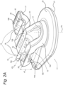
- Fig. 2A shows a perspective view of the ERD 10 according to the present invention with the device in open state.
- the depicted ERD 10 is a one-component device comprising integrally formed elements, obtained by a moulding process including a base plate 11, a guiding part 12 and a fixation part 15.
- the base plate 11 has a lower surface 21 and an upper surface 22 defining a thickness of the base plate 11 with the lower and upper surfaces 21, 22 connected by a passage 13 having a central axis P2.
- the base plate 11 is made of soft and elastic silicone rubber.
- the guiding part 12 comprises a first section 12a with a semi-circular concave channel 14 open to the top side thereof, extending upwards from the passage 13 in a curve relative to the base plate 11.
- the guiding part 12 further comprises a second section 12b, contiguous to the first section 12a, where the same concave channel 14 extends parallel to the base plate 11, at a vertical distance d 1 offset from the base plate 11.
- the concave channel 14 extends from the first section 12a to the second section 12b, along a longitudinal axis P3, between two planar surfaces, namely a clip side surface 14a and a hinge side surface 14b.
- a radius of the channel 14 in the first section 12a varies from the passage 13 to the second section 12b, where the radius is fixed to a value R1.
- the angle between P2 and P3 at the second section is 90 degrees.
- the fixation part 15 is located in the second section 12b of the guiding part 12 and surrounds or encircles the concave channel 14. It includes a clip closure 16 a closing part 17 and a hinge 23.
- the closing part 17 comprises silicon rubber and is connected via the hinge 23 at the hinge side surface 14b of the concave channel 14 so as to be selectively rotatable by 180° around an axis P4. In this open state of the ERD 10, the closing part 17 is defined to be positioned at angle 0.
- the closing part 17 includes a second channel 32 of similar size to the semi-circular concave channel 14 in the second section 12b.
- the clip closure 16 consists of first and second interlocking elements 16a, 16b, the first element 16a protrudes from the clip side surface 14a of the concave channel 14 and comprises a barbed finger 28.
- the second element 16b is provided on the closing part 17 and comprises a slot 26.
- the barbed finger 28 is receivable in the slot 26 when the fixation part 15 is in a closed state.
- the interlocking elements 16a, 16b of the clip closure are made of polybutylene terephthalate (PBT) and are embedded in silicon rubber which forms the remainder of the fixation part 15.
- PBT is known for its good cross-linking with silicone during injection moulding, resulting in an improved adhesion of the overmoulded silicone, as disclosed in WO2017216068A1 .
- the silicone rubber also provides a soft cover to the rigid PBT.
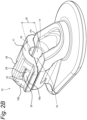
- Fig. 2B shows the same view of the ERD 10 with the device in a closed state.
- the closing part 17 In the closed state the closing part 17 is positioned at an angle of 180° relative to the open state, after rotation of the closing part 17 comprising the first interlocking element 16a to engage with the second interlocking element 16b. In this position the barbed finger 28 is thus engaged in the slot 26.
- the closure of the clip closure 16 positions the second channel 32 of the closing part 17 above the semi-circular concave channel 14, to form a tubular channel 34 of diameter d 2 .
- the fixation part 15 thus comprises rigid plastic overmoulded with silicone rubber to form the tubular channel 34.
- Fig. 2B also shows a depression 36 on an upper side of the closing part 17, which indicates a preferred location for a user's finger.
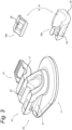
- Fig. 3 shows an exploded view of the ERD 10 according to the present invention with the device in open state.
- the main body 40 of the ERD 10 comprising the base plate 11, the guiding part 12 and the fixation part 15, including the closing part 17 and the hinge 23 are all made in one piece of soft and elastic silicone rubber. They are shown separately from the interlocking elements 16a, 16b of the clip closure 16, which are made of PBT and comprise the barbed finger 28 and the slot 26.
- the first interlocking element 16a comprises a curved, channel section 30 from which the barbed finger 28 extends.
- the second interlocking element 16b is also generally curved with a similar curvature to the channel section 30 and the concave channel 14.
- Fig. 4 shows a top view of the ERD 10 according to the invention with the device in closed state.
- the passage 13 can be seen to have a substantially circular shape. Also visible in this view is the depression 36 on the upper side of the closing part 17.
- Fig. 5 shows a front view of the ERD 10 according to the present invention with the device in closed state.
- the closing element 17 closes the top side of the concave channel 14 by fitting of the slot 26 over the barbed finger 28, whereby a catheter (not shown) can be locked within the tubular channel 34. This can be achieved by applying a squeezing pressure laterally to the ERD 10, whereby a user's finger engages the depression 36.
- the clip side surface 14a and hinge side surface 14b lie in the same plane which is referred to as the plane of opening of the fixation part 15.
- the plane of opening is parallel to the base plate 11. It will be understood that in alternative embodiments, the plane of opening may be angled with respect to the base, such that the hinge 23 is lowered. This may ensure that a force required to close the fixation part is directed sideways rather than downwards.
- the interlocking elements 16a, 16b encircle the tubular channel 34.
- the first interlocking element 16a subtends an angle of around 180 degrees, extending over the full extent of the concave channel 14.
- the second interlocking element subtends an angle of around 90 degrees or around half of the closing element 17.
- around 270 degrees of the circumference of the tubular channel is enclosed by the rigid polymeric material of the interlocking elements 16a, 16b, while the remaining 90 degrees, including the hinge 23 comprises only elastomeric polymer material. This balance between rigid and elastomeric materials and the resilience of the elastomeric material determines the amount of flexibility or resilience in the fixation part 15.
Landscapes
- Health & Medical Sciences (AREA)
- Life Sciences & Earth Sciences (AREA)
- Veterinary Medicine (AREA)
- Animal Behavior & Ethology (AREA)
- General Health & Medical Sciences (AREA)
- Public Health (AREA)
- Pulmonology (AREA)
- Biophysics (AREA)
- Engineering & Computer Science (AREA)
- Anesthesiology (AREA)
- Biomedical Technology (AREA)
- Heart & Thoracic Surgery (AREA)
- Hematology (AREA)
- Orthopedics, Nursing, And Contraception (AREA)
- Media Introduction/Drainage Providing Device (AREA)
Claims (15)
- Externe Haltevorrichtung (10) zum Befestigen eines Katheters (1), der aus einem Stoma (3) austritt, die Folgendes umfasst:eine Basisplatte (11) zum Eingriff mit dem Unterleib (4) eines Patienten;einen Führungsteil (12), der einen konkaven Kanal (14) umfasst, der zu seiner Oberseite offen ist, um den Katheter (1) von der Basisplatte (11) durch einen ersten gekrümmten Abschnitt (12a) des konkaven Kanals (14) zu einer im Wesentlichen parallelen Position relativ zu der Basisplatte (11) in einem zweiten Abschnitt (12b) des konkaven Kanals (14) zu führen;einen Befestigungsteil (15) mit einem offenen Zustand und einem geschlossenen Zustand zum Umschließen und Befestigen des Katheters (1) innerhalb des zweiten Abschnitts (12b) des Führungsteils (12), wobei das Befestigungsteil (15) einen Clipverschluss (16) umfasst, der zwei Verriegelungselemente (16a, 16b) und ein Scharnier (23) dazwischen umfasst, wobei mindestens eines der Verriegelungselemente (16a, 16b) ein starres Polymermaterial umfasst und zumindest die Basisplatte (11) ein Elastomerpolymer umfasst, gekennzeichnet dadurch, dass das Scharnier (23) auch ein Elastomerpolymer umfasst, die Basisplatte (11), der Führungsteil (12) und der Befestigungsteil (15) einstückig als eine einzige Vorrichtung gebildet sind und das starre Polymermaterial zumindest teilweise durch das Elastomerpolymer überformt ist.
- Externe Haltevorrichtung nach Anspruch 1, wobei beide Verriegelungselemente (16a, 16b) des Clipverschlusses (16) ein starres Polymermaterial umfassen.
- Externe Haltevorrichtung nach Anspruch 1 oder Anspruch 2, wobei mindestens eines der beiden Verriegelungselemente (16a, 16b) durch Drehung des Scharniers (23) in den offenen Zustand um einen Winkel von mindestens 60° gedreht werden kann.
- Externe Haltevorrichtung nach Anspruch 2 oder Anspruch 3, wobei das starre Polymermaterial nur teilweise den Katheter (1) in dem geschlossenen Zustand umschließt, wobei es vorzugsweise zwischen 90 und 330 Grad abdeckt.
- Externe Haltevorrichtung nach einem der Ansprüche 2-4, wobei die beiden Verriegelungselemente (16a, 16b) einen Schlitz (26) und einen mit Widerhaken versehenen Finger (26) umfassen, die ineinandergreifen.
- Externe Haltevorrichtung nach einem der vorhergehenden Ansprüche, wobei das starre Polymermaterial ein Polyester ist, vorzugsweise Polybutylterephthalat (PBT).
- Externe Haltevorrichtung nach einem der vorhergehenden Ansprüche, wobei das Elastomerpolymer Silikon, Polyurethan oder Copolymere davon umfasst.
- Externe Haltevorrichtung nach einem der vorhergehenden Ansprüche, wobei ein Verschlussteil (17) den konkaven Kanal (14) an seiner von der Basisplatte (11) entfernten Oberseite verschließt und ein erstes (16a) der beiden Verriegelungselemente an dem Verschlussteil (17) vorgesehen ist.
- Externe Haltevorrichtung nach Anspruch 8, wobei der Verschlussteil (17) auch das Elastomerpolymer umfasst und ausreichend elastisch ist, so dass Katheter mit einem Radius, der vorzugsweise bis zu 30 %, größer als ein Radius des konkaven Kanals (14) ist, in dem Befestigungsteil (15) gehalten werden können.
- Externe Haltevorrichtung nach einem der vorhergehenden Ansprüche, wobei die Basisplatte (11) einen Durchgang (13) zum reibungsfreien Eingriff mit dem Katheter (1) umfasst.
- Externe Haltevorrichtung nach einem der vorhergehenden Ansprüche, wobei eine Öffnungsebene des Befestigungsteils (15) in einem Winkel zu der Ebene der Basisplatte (11) liegt, vorzugsweise in einem Winkel von 20 Grad bis 90 Grad.
- Verfahren zum Herstellen der externen Haltevorrichtung (10) nach Anspruch 1 zum Befestigen eines Katheters (1), der aus einem Stoma (3) austritt, das Folgendes umfasst:Bereitstellen eines Clipverschlusses (16), der ein erstes (16a) und zweites (16b) ineinandergreifendes starres Polymerelement umfasst;Anordnen der besagten Elemente (16a, 16b) in einer Form;Überformen eines Elastomerpolymers über das erste (16a) und zweite (16b) ineinandergreifende starre Polymerelement, um einen konkaven Kanal (14) mit einem gekrümmten ersten Abschnitt (12a), einem geraden zweiten Abschnitt (12b), einem Scharnier (23) und einer Basisplatte (11) zu bilden, wobei das erste (16a) und zweite (16b) ineinandergreifende starre Polymerelement ineinandergreifen können, um den Katheter (1) innerhalb des zweiten Abschnitts (12b) zu umschließen und zu befestigen.
- Verfahren nach Anspruch 12, wobei das Formen mit dem ersten (16a) und zweiten (16b) ineinandergreifenden starren Polymerelement in einem offenen Zustand in einem Winkel von 160 Grad bis 180 Grad relativ zu ihrem geschlossenen Zustand erfolgt.
- Verfahren nach Anspruch 12 oder Anspruch 13, das ferner das Nachhärten der externen Haltevorrichtung (10) in einem geschlossenen Zustand, in dem der Clipverschluss (16) geschlossen ist, oder in einem halboffenen Zustand umfasst.
- Verfahren nach Anspruch 12 oder Anspruch 13, das ferner das Nachhärten der externen Haltevorrichtung (10) in einer offenen Position umfasst, so dass es sichtbar ist, wenn sich der Clipverschluss (16) geöffnet hat.
Applications Claiming Priority (2)
| Application Number | Priority Date | Filing Date | Title |
|---|---|---|---|
| PCT/EP2019/084716 WO2021115594A1 (en) | 2019-12-11 | 2019-12-11 | External retaining device for a catheter |
| PCT/EP2020/085568 WO2021116302A1 (en) | 2019-12-11 | 2020-12-10 | External retaining device for a catheter |
Publications (2)
| Publication Number | Publication Date |
|---|---|
| EP4072502A1 EP4072502A1 (de) | 2022-10-19 |
| EP4072502B1 true EP4072502B1 (de) | 2024-01-31 |
Family
ID=68987679
Family Applications (1)
| Application Number | Title | Priority Date | Filing Date |
|---|---|---|---|
| EP20820216.8A Active EP4072502B1 (de) | 2019-12-11 | 2020-12-10 | Externe haltevorrichtung für einen katheter |
Country Status (2)
| Country | Link |
|---|---|
| EP (1) | EP4072502B1 (de) |
| WO (2) | WO2021115594A1 (de) |
Families Citing this family (1)
| Publication number | Priority date | Publication date | Assignee | Title |
|---|---|---|---|---|
| KR20230120657A (ko) * | 2020-12-16 | 2023-08-17 | 애퍼처 서지컬 리미티드 | 고정 장치의 개선 |
Family Cites Families (8)
| Publication number | Priority date | Publication date | Assignee | Title |
|---|---|---|---|---|
| NL9301810A (nl) | 1993-10-19 | 1995-05-16 | Nutricia Nv | Beugel voor verbindingsinrichting. |
| US6231547B1 (en) * | 1999-02-18 | 2001-05-15 | Abbott Laboratories | External retaining device for a catheter and catheter assembly and method using same |
| US6572588B1 (en) * | 2000-03-10 | 2003-06-03 | Venetec International, Inc. | Medical anchoring system |
| US6482183B1 (en) * | 2000-05-10 | 2002-11-19 | Gudrun Pausch | Apparatus for the fixation of a percutaneous flexible line |
| AU2003231269B2 (en) * | 2002-05-01 | 2008-08-28 | Venetec International, Inc. | Medical line securement device |
| US9480821B2 (en) * | 2008-06-30 | 2016-11-01 | Venetec International, Inc. | Anchoring system for a medical article |
| WO2015020882A1 (en) * | 2013-08-05 | 2015-02-12 | 3M Innovative Properties Company | Catheter securement device |
| WO2017216068A1 (en) | 2016-06-15 | 2017-12-21 | Raumedic Ag | Probe device for insertion into a body of a patient, and tube/connector assembly |
-
2019
- 2019-12-11 WO PCT/EP2019/084716 patent/WO2021115594A1/en not_active Ceased
-
2020
- 2020-12-10 WO PCT/EP2020/085568 patent/WO2021116302A1/en not_active Ceased
- 2020-12-10 EP EP20820216.8A patent/EP4072502B1/de active Active
Also Published As
| Publication number | Publication date |
|---|---|
| WO2021116302A1 (en) | 2021-06-17 |
| WO2021115594A1 (en) | 2021-06-17 |
| EP4072502A1 (de) | 2022-10-19 |
Similar Documents
| Publication | Publication Date | Title |
|---|---|---|
| US4834712A (en) | Tube fixation device | |
| JP7708450B2 (ja) | 外付けカテーテル安定化装置 | |
| US6231547B1 (en) | External retaining device for a catheter and catheter assembly and method using same | |
| EP1713529B1 (de) | Selbstnähende ankervorrichtung für einen katheter | |
| JP4679026B2 (ja) | カテーテル等の取付装置 | |
| CA2462829C (en) | Esophagus stoma button | |
| US9079006B1 (en) | Suture locking mechanism | |
| JP2014532450A (ja) | ロックするカテーテルハブ | |
| US20140148778A1 (en) | Tube Anchor Assembly | |
| EP4072502B1 (de) | Externe haltevorrichtung für einen katheter | |
| US20210307947A1 (en) | Over molded implantable device to protect tubing from puncture | |
| KR20110050193A (ko) | 뇨관호스 고정 장치 | |
| JP4119904B2 (ja) | 医療用カテーテルの固定具 | |
| CN221308918U (zh) | 具有导引止挡片的消化道造瘘构造 | |
| TWI799979B (zh) | 具止逆功能的鼻胃管 | |
| US20250229060A1 (en) | Retainer System for Catheter | |
| JP4527083B2 (ja) | 食道瘻ボタン | |
| JP2010213895A (ja) | 瘻孔用カテーテル |
Legal Events
| Date | Code | Title | Description |
|---|---|---|---|
| STAA | Information on the status of an ep patent application or granted ep patent |
Free format text: STATUS: UNKNOWN |
|
| STAA | Information on the status of an ep patent application or granted ep patent |
Free format text: STATUS: THE INTERNATIONAL PUBLICATION HAS BEEN MADE |
|
| PUAI | Public reference made under article 153(3) epc to a published international application that has entered the european phase |
Free format text: ORIGINAL CODE: 0009012 |
|
| STAA | Information on the status of an ep patent application or granted ep patent |
Free format text: STATUS: REQUEST FOR EXAMINATION WAS MADE |
|
| 17P | Request for examination filed |
Effective date: 20220615 |
|
| AK | Designated contracting states |
Kind code of ref document: A1 Designated state(s): AL AT BE BG CH CY CZ DE DK EE ES FI FR GB GR HR HU IE IS IT LI LT LU LV MC MK MT NL NO PL PT RO RS SE SI SK SM TR |
|
| DAV | Request for validation of the european patent (deleted) | ||
| DAX | Request for extension of the european patent (deleted) | ||
| GRAP | Despatch of communication of intention to grant a patent |
Free format text: ORIGINAL CODE: EPIDOSNIGR1 |
|
| STAA | Information on the status of an ep patent application or granted ep patent |
Free format text: STATUS: GRANT OF PATENT IS INTENDED |
|
| GRAJ | Information related to disapproval of communication of intention to grant by the applicant or resumption of examination proceedings by the epo deleted |
Free format text: ORIGINAL CODE: EPIDOSDIGR1 |
|
| GRAP | Despatch of communication of intention to grant a patent |
Free format text: ORIGINAL CODE: EPIDOSNIGR1 |
|
| GRAJ | Information related to disapproval of communication of intention to grant by the applicant or resumption of examination proceedings by the epo deleted |
Free format text: ORIGINAL CODE: EPIDOSDIGR1 |
|
| GRAP | Despatch of communication of intention to grant a patent |
Free format text: ORIGINAL CODE: EPIDOSNIGR1 |
|
| STAA | Information on the status of an ep patent application or granted ep patent |
Free format text: STATUS: REQUEST FOR EXAMINATION WAS MADE |
|
| INTG | Intention to grant announced |
Effective date: 20230525 |
|
| GRAP | Despatch of communication of intention to grant a patent |
Free format text: ORIGINAL CODE: EPIDOSNIGR1 |
|
| STAA | Information on the status of an ep patent application or granted ep patent |
Free format text: STATUS: GRANT OF PATENT IS INTENDED |
|
| INTG | Intention to grant announced |
Effective date: 20230609 |
|
| INTC | Intention to grant announced (deleted) | ||
| INTG | Intention to grant announced |
Effective date: 20230628 |
|
| GRAS | Grant fee paid |
Free format text: ORIGINAL CODE: EPIDOSNIGR3 |
|
| GRAA | (expected) grant |
Free format text: ORIGINAL CODE: 0009210 |
|
| STAA | Information on the status of an ep patent application or granted ep patent |
Free format text: STATUS: THE PATENT HAS BEEN GRANTED |
|
| AK | Designated contracting states |
Kind code of ref document: B1 Designated state(s): AL AT BE BG CH CY CZ DE DK EE ES FI FR GB GR HR HU IE IS IT LI LT LU LV MC MK MT NL NO PL PT RO RS SE SI SK SM TR |
|
| REG | Reference to a national code |
Ref country code: GB Ref legal event code: FG4D Ref country code: CH Ref legal event code: EP |
|
| P01 | Opt-out of the competence of the unified patent court (upc) registered |
Effective date: 20231228 |
|
| REG | Reference to a national code |
Ref country code: DE Ref legal event code: R096 Ref document number: 602020025067 Country of ref document: DE |
|
| REG | Reference to a national code |
Ref country code: IE Ref legal event code: FG4D |
|
| REG | Reference to a national code |
Ref country code: LT Ref legal event code: MG9D |
|
| REG | Reference to a national code |
Ref country code: NL Ref legal event code: MP Effective date: 20240131 |
|
| PG25 | Lapsed in a contracting state [announced via postgrant information from national office to epo] |
Ref country code: IS Free format text: LAPSE BECAUSE OF FAILURE TO SUBMIT A TRANSLATION OF THE DESCRIPTION OR TO PAY THE FEE WITHIN THE PRESCRIBED TIME-LIMIT Effective date: 20240531 |
|
| PG25 | Lapsed in a contracting state [announced via postgrant information from national office to epo] |
Ref country code: LT Free format text: LAPSE BECAUSE OF FAILURE TO SUBMIT A TRANSLATION OF THE DESCRIPTION OR TO PAY THE FEE WITHIN THE PRESCRIBED TIME-LIMIT Effective date: 20240131 |
|
| PG25 | Lapsed in a contracting state [announced via postgrant information from national office to epo] |
Ref country code: GR Free format text: LAPSE BECAUSE OF FAILURE TO SUBMIT A TRANSLATION OF THE DESCRIPTION OR TO PAY THE FEE WITHIN THE PRESCRIBED TIME-LIMIT Effective date: 20240501 |
|
| REG | Reference to a national code |
Ref country code: AT Ref legal event code: MK05 Ref document number: 1653377 Country of ref document: AT Kind code of ref document: T Effective date: 20240131 |
|
| PG25 | Lapsed in a contracting state [announced via postgrant information from national office to epo] |
Ref country code: RS Free format text: LAPSE BECAUSE OF FAILURE TO SUBMIT A TRANSLATION OF THE DESCRIPTION OR TO PAY THE FEE WITHIN THE PRESCRIBED TIME-LIMIT Effective date: 20240430 Ref country code: HR Free format text: LAPSE BECAUSE OF FAILURE TO SUBMIT A TRANSLATION OF THE DESCRIPTION OR TO PAY THE FEE WITHIN THE PRESCRIBED TIME-LIMIT Effective date: 20240131 Ref country code: NL Free format text: LAPSE BECAUSE OF FAILURE TO SUBMIT A TRANSLATION OF THE DESCRIPTION OR TO PAY THE FEE WITHIN THE PRESCRIBED TIME-LIMIT Effective date: 20240131 |
|
| PG25 | Lapsed in a contracting state [announced via postgrant information from national office to epo] |
Ref country code: ES Free format text: LAPSE BECAUSE OF FAILURE TO SUBMIT A TRANSLATION OF THE DESCRIPTION OR TO PAY THE FEE WITHIN THE PRESCRIBED TIME-LIMIT Effective date: 20240131 |
|
| PG25 | Lapsed in a contracting state [announced via postgrant information from national office to epo] |
Ref country code: AT Free format text: LAPSE BECAUSE OF FAILURE TO SUBMIT A TRANSLATION OF THE DESCRIPTION OR TO PAY THE FEE WITHIN THE PRESCRIBED TIME-LIMIT Effective date: 20240131 |
|
| PG25 | Lapsed in a contracting state [announced via postgrant information from national office to epo] |
Ref country code: RS Free format text: LAPSE BECAUSE OF FAILURE TO SUBMIT A TRANSLATION OF THE DESCRIPTION OR TO PAY THE FEE WITHIN THE PRESCRIBED TIME-LIMIT Effective date: 20240430 Ref country code: NO Free format text: LAPSE BECAUSE OF FAILURE TO SUBMIT A TRANSLATION OF THE DESCRIPTION OR TO PAY THE FEE WITHIN THE PRESCRIBED TIME-LIMIT Effective date: 20240430 Ref country code: NL Free format text: LAPSE BECAUSE OF FAILURE TO SUBMIT A TRANSLATION OF THE DESCRIPTION OR TO PAY THE FEE WITHIN THE PRESCRIBED TIME-LIMIT Effective date: 20240131 Ref country code: LT Free format text: LAPSE BECAUSE OF FAILURE TO SUBMIT A TRANSLATION OF THE DESCRIPTION OR TO PAY THE FEE WITHIN THE PRESCRIBED TIME-LIMIT Effective date: 20240131 Ref country code: IS Free format text: LAPSE BECAUSE OF FAILURE TO SUBMIT A TRANSLATION OF THE DESCRIPTION OR TO PAY THE FEE WITHIN THE PRESCRIBED TIME-LIMIT Effective date: 20240531 Ref country code: HR Free format text: LAPSE BECAUSE OF FAILURE TO SUBMIT A TRANSLATION OF THE DESCRIPTION OR TO PAY THE FEE WITHIN THE PRESCRIBED TIME-LIMIT Effective date: 20240131 Ref country code: GR Free format text: LAPSE BECAUSE OF FAILURE TO SUBMIT A TRANSLATION OF THE DESCRIPTION OR TO PAY THE FEE WITHIN THE PRESCRIBED TIME-LIMIT Effective date: 20240501 Ref country code: FI Free format text: LAPSE BECAUSE OF FAILURE TO SUBMIT A TRANSLATION OF THE DESCRIPTION OR TO PAY THE FEE WITHIN THE PRESCRIBED TIME-LIMIT Effective date: 20240131 Ref country code: ES Free format text: LAPSE BECAUSE OF FAILURE TO SUBMIT A TRANSLATION OF THE DESCRIPTION OR TO PAY THE FEE WITHIN THE PRESCRIBED TIME-LIMIT Effective date: 20240131 Ref country code: BG Free format text: LAPSE BECAUSE OF FAILURE TO SUBMIT A TRANSLATION OF THE DESCRIPTION OR TO PAY THE FEE WITHIN THE PRESCRIBED TIME-LIMIT Effective date: 20240131 Ref country code: AT Free format text: LAPSE BECAUSE OF FAILURE TO SUBMIT A TRANSLATION OF THE DESCRIPTION OR TO PAY THE FEE WITHIN THE PRESCRIBED TIME-LIMIT Effective date: 20240131 |
|
| PG25 | Lapsed in a contracting state [announced via postgrant information from national office to epo] |
Ref country code: PT Free format text: LAPSE BECAUSE OF FAILURE TO SUBMIT A TRANSLATION OF THE DESCRIPTION OR TO PAY THE FEE WITHIN THE PRESCRIBED TIME-LIMIT Effective date: 20240531 Ref country code: PL Free format text: LAPSE BECAUSE OF FAILURE TO SUBMIT A TRANSLATION OF THE DESCRIPTION OR TO PAY THE FEE WITHIN THE PRESCRIBED TIME-LIMIT Effective date: 20240131 |
|
| PG25 | Lapsed in a contracting state [announced via postgrant information from national office to epo] |
Ref country code: SE Free format text: LAPSE BECAUSE OF FAILURE TO SUBMIT A TRANSLATION OF THE DESCRIPTION OR TO PAY THE FEE WITHIN THE PRESCRIBED TIME-LIMIT Effective date: 20240131 Ref country code: PT Free format text: LAPSE BECAUSE OF FAILURE TO SUBMIT A TRANSLATION OF THE DESCRIPTION OR TO PAY THE FEE WITHIN THE PRESCRIBED TIME-LIMIT Effective date: 20240531 Ref country code: PL Free format text: LAPSE BECAUSE OF FAILURE TO SUBMIT A TRANSLATION OF THE DESCRIPTION OR TO PAY THE FEE WITHIN THE PRESCRIBED TIME-LIMIT Effective date: 20240131 Ref country code: LV Free format text: LAPSE BECAUSE OF FAILURE TO SUBMIT A TRANSLATION OF THE DESCRIPTION OR TO PAY THE FEE WITHIN THE PRESCRIBED TIME-LIMIT Effective date: 20240131 |
|
| PG25 | Lapsed in a contracting state [announced via postgrant information from national office to epo] |
Ref country code: DK Free format text: LAPSE BECAUSE OF FAILURE TO SUBMIT A TRANSLATION OF THE DESCRIPTION OR TO PAY THE FEE WITHIN THE PRESCRIBED TIME-LIMIT Effective date: 20240131 |
|
| PG25 | Lapsed in a contracting state [announced via postgrant information from national office to epo] |
Ref country code: SM Free format text: LAPSE BECAUSE OF FAILURE TO SUBMIT A TRANSLATION OF THE DESCRIPTION OR TO PAY THE FEE WITHIN THE PRESCRIBED TIME-LIMIT Effective date: 20240131 |
|
| PG25 | Lapsed in a contracting state [announced via postgrant information from national office to epo] |
Ref country code: EE Free format text: LAPSE BECAUSE OF FAILURE TO SUBMIT A TRANSLATION OF THE DESCRIPTION OR TO PAY THE FEE WITHIN THE PRESCRIBED TIME-LIMIT Effective date: 20240131 Ref country code: CZ Free format text: LAPSE BECAUSE OF FAILURE TO SUBMIT A TRANSLATION OF THE DESCRIPTION OR TO PAY THE FEE WITHIN THE PRESCRIBED TIME-LIMIT Effective date: 20240131 |
|
| PG25 | Lapsed in a contracting state [announced via postgrant information from national office to epo] |
Ref country code: SK Free format text: LAPSE BECAUSE OF FAILURE TO SUBMIT A TRANSLATION OF THE DESCRIPTION OR TO PAY THE FEE WITHIN THE PRESCRIBED TIME-LIMIT Effective date: 20240131 |
|
| PG25 | Lapsed in a contracting state [announced via postgrant information from national office to epo] |
Ref country code: SM Free format text: LAPSE BECAUSE OF FAILURE TO SUBMIT A TRANSLATION OF THE DESCRIPTION OR TO PAY THE FEE WITHIN THE PRESCRIBED TIME-LIMIT Effective date: 20240131 Ref country code: SK Free format text: LAPSE BECAUSE OF FAILURE TO SUBMIT A TRANSLATION OF THE DESCRIPTION OR TO PAY THE FEE WITHIN THE PRESCRIBED TIME-LIMIT Effective date: 20240131 Ref country code: RO Free format text: LAPSE BECAUSE OF FAILURE TO SUBMIT A TRANSLATION OF THE DESCRIPTION OR TO PAY THE FEE WITHIN THE PRESCRIBED TIME-LIMIT Effective date: 20240131 Ref country code: EE Free format text: LAPSE BECAUSE OF FAILURE TO SUBMIT A TRANSLATION OF THE DESCRIPTION OR TO PAY THE FEE WITHIN THE PRESCRIBED TIME-LIMIT Effective date: 20240131 Ref country code: DK Free format text: LAPSE BECAUSE OF FAILURE TO SUBMIT A TRANSLATION OF THE DESCRIPTION OR TO PAY THE FEE WITHIN THE PRESCRIBED TIME-LIMIT Effective date: 20240131 Ref country code: CZ Free format text: LAPSE BECAUSE OF FAILURE TO SUBMIT A TRANSLATION OF THE DESCRIPTION OR TO PAY THE FEE WITHIN THE PRESCRIBED TIME-LIMIT Effective date: 20240131 |
|
| REG | Reference to a national code |
Ref country code: DE Ref legal event code: R097 Ref document number: 602020025067 Country of ref document: DE |
|
| PG25 | Lapsed in a contracting state [announced via postgrant information from national office to epo] |
Ref country code: IT Free format text: LAPSE BECAUSE OF FAILURE TO SUBMIT A TRANSLATION OF THE DESCRIPTION OR TO PAY THE FEE WITHIN THE PRESCRIBED TIME-LIMIT Effective date: 20240131 |
|
| PLBE | No opposition filed within time limit |
Free format text: ORIGINAL CODE: 0009261 |
|
| STAA | Information on the status of an ep patent application or granted ep patent |
Free format text: STATUS: NO OPPOSITION FILED WITHIN TIME LIMIT |
|
| PG25 | Lapsed in a contracting state [announced via postgrant information from national office to epo] |
Ref country code: IT Free format text: LAPSE BECAUSE OF FAILURE TO SUBMIT A TRANSLATION OF THE DESCRIPTION OR TO PAY THE FEE WITHIN THE PRESCRIBED TIME-LIMIT Effective date: 20240131 |
|
| 26N | No opposition filed |
Effective date: 20241101 |
|
| PG25 | Lapsed in a contracting state [announced via postgrant information from national office to epo] |
Ref country code: SI Free format text: LAPSE BECAUSE OF FAILURE TO SUBMIT A TRANSLATION OF THE DESCRIPTION OR TO PAY THE FEE WITHIN THE PRESCRIBED TIME-LIMIT Effective date: 20240131 |
|
| PG25 | Lapsed in a contracting state [announced via postgrant information from national office to epo] |
Ref country code: MC Free format text: LAPSE BECAUSE OF FAILURE TO SUBMIT A TRANSLATION OF THE DESCRIPTION OR TO PAY THE FEE WITHIN THE PRESCRIBED TIME-LIMIT Effective date: 20240131 |
|
| REG | Reference to a national code |
Ref country code: CH Ref legal event code: PL |
|
| PG25 | Lapsed in a contracting state [announced via postgrant information from national office to epo] |
Ref country code: LU Free format text: LAPSE BECAUSE OF NON-PAYMENT OF DUE FEES Effective date: 20241210 |
|
| GBPC | Gb: european patent ceased through non-payment of renewal fee |
Effective date: 20241210 |
|
| REG | Reference to a national code |
Ref country code: BE Ref legal event code: MM Effective date: 20241231 |
|
| PG25 | Lapsed in a contracting state [announced via postgrant information from national office to epo] |
Ref country code: BE Free format text: LAPSE BECAUSE OF NON-PAYMENT OF DUE FEES Effective date: 20241231 Ref country code: GB Free format text: LAPSE BECAUSE OF NON-PAYMENT OF DUE FEES Effective date: 20241210 |
|
| PG25 | Lapsed in a contracting state [announced via postgrant information from national office to epo] |
Ref country code: CH Free format text: LAPSE BECAUSE OF NON-PAYMENT OF DUE FEES Effective date: 20241231 |
|
| PG25 | Lapsed in a contracting state [announced via postgrant information from national office to epo] |
Ref country code: IE Free format text: LAPSE BECAUSE OF NON-PAYMENT OF DUE FEES Effective date: 20241210 |
|
| PGFP | Annual fee paid to national office [announced via postgrant information from national office to epo] |
Ref country code: FR Payment date: 20251223 Year of fee payment: 6 |
|
| PGFP | Annual fee paid to national office [announced via postgrant information from national office to epo] |
Ref country code: DE Payment date: 20251229 Year of fee payment: 6 |