EP4072167A1 - Procédé, appareil et système de positionnement - Google Patents
Procédé, appareil et système de positionnement Download PDFInfo
- Publication number
- EP4072167A1 EP4072167A1 EP19958166.1A EP19958166A EP4072167A1 EP 4072167 A1 EP4072167 A1 EP 4072167A1 EP 19958166 A EP19958166 A EP 19958166A EP 4072167 A1 EP4072167 A1 EP 4072167A1
- Authority
- EP
- European Patent Office
- Prior art keywords
- prs resource
- resource identifiers
- measured
- angle
- power
- Prior art date
- Legal status (The legal status is an assumption and is not a legal conclusion. Google has not performed a legal analysis and makes no representation as to the accuracy of the status listed.)
- Pending
Links
Images


Classifications
-
- H—ELECTRICITY
- H04—ELECTRIC COMMUNICATION TECHNIQUE
- H04W—WIRELESS COMMUNICATION NETWORKS
- H04W4/00—Services specially adapted for wireless communication networks; Facilities therefor
- H04W4/02—Services making use of location information
- H04W4/025—Services making use of location information using location based information parameters
- H04W4/026—Services making use of location information using location based information parameters using orientation information, e.g. compass
-
- G—PHYSICS
- G01—MEASURING; TESTING
- G01S—RADIO DIRECTION-FINDING; RADIO NAVIGATION; DETERMINING DISTANCE OR VELOCITY BY USE OF RADIO WAVES; LOCATING OR PRESENCE-DETECTING BY USE OF THE REFLECTION OR RERADIATION OF RADIO WAVES; ANALOGOUS ARRANGEMENTS USING OTHER WAVES
- G01S5/00—Position-fixing by co-ordinating two or more direction or position line determinations; Position-fixing by co-ordinating two or more distance determinations
- G01S5/0009—Transmission of position information to remote stations
- G01S5/0018—Transmission from mobile station to base station
- G01S5/0036—Transmission from mobile station to base station of measured values, i.e. measurement on mobile and position calculation on base station
-
- G—PHYSICS
- G01—MEASURING; TESTING
- G01S—RADIO DIRECTION-FINDING; RADIO NAVIGATION; DETERMINING DISTANCE OR VELOCITY BY USE OF RADIO WAVES; LOCATING OR PRESENCE-DETECTING BY USE OF THE REFLECTION OR RERADIATION OF RADIO WAVES; ANALOGOUS ARRANGEMENTS USING OTHER WAVES
- G01S5/00—Position-fixing by co-ordinating two or more direction or position line determinations; Position-fixing by co-ordinating two or more distance determinations
- G01S5/02—Position-fixing by co-ordinating two or more direction or position line determinations; Position-fixing by co-ordinating two or more distance determinations using radio waves
- G01S5/0205—Details
- G01S5/0236—Assistance data, e.g. base station almanac
-
- H—ELECTRICITY
- H04—ELECTRIC COMMUNICATION TECHNIQUE
- H04L—TRANSMISSION OF DIGITAL INFORMATION, e.g. TELEGRAPHIC COMMUNICATION
- H04L5/00—Arrangements affording multiple use of the transmission path
-
- H—ELECTRICITY
- H04—ELECTRIC COMMUNICATION TECHNIQUE
- H04L—TRANSMISSION OF DIGITAL INFORMATION, e.g. TELEGRAPHIC COMMUNICATION
- H04L5/00—Arrangements affording multiple use of the transmission path
- H04L5/003—Arrangements for allocating sub-channels of the transmission path
- H04L5/0048—Allocation of pilot signals, i.e. of signals known to the receiver
- H04L5/0051—Allocation of pilot signals, i.e. of signals known to the receiver of dedicated pilots, i.e. pilots destined for a single user or terminal
-
- H—ELECTRICITY
- H04—ELECTRIC COMMUNICATION TECHNIQUE
- H04W—WIRELESS COMMUNICATION NETWORKS
- H04W64/00—Locating users or terminals or network equipment for network management purposes, e.g. mobility management
-
- G—PHYSICS
- G01—MEASURING; TESTING
- G01S—RADIO DIRECTION-FINDING; RADIO NAVIGATION; DETERMINING DISTANCE OR VELOCITY BY USE OF RADIO WAVES; LOCATING OR PRESENCE-DETECTING BY USE OF THE REFLECTION OR RERADIATION OF RADIO WAVES; ANALOGOUS ARRANGEMENTS USING OTHER WAVES
- G01S5/00—Position-fixing by co-ordinating two or more direction or position line determinations; Position-fixing by co-ordinating two or more distance determinations
- G01S5/02—Position-fixing by co-ordinating two or more direction or position line determinations; Position-fixing by co-ordinating two or more distance determinations using radio waves
Definitions
- This application relates to the field of positioning technologies, and in particular, to a positioning method, an apparatus, and a system.
- Existing positioning methods mainly include a user equipment based (UE-based) positioning method, a user equipment assisted (UE-assisted) positioning method, and a standalone (standalone) positioning method.
- UE-based positioning method when assistance data is available, UE is not only responsible for providing a measurement result, but also responsible for performing location calculation based on the measurement result and the assistance data.
- UE-assisted positioning method when assistance data is available, the UE is only responsible for providing a measurement result and does not perform location calculation, and a location management function (location management function, LMF) network element performs location calculation based on the measurement result and the assistance data.
- LMF location management function
- the UE performs measurement and location calculation without network assistance data. It can be learned that the assistance data may assist the LMF network element or the UE in performing location calculation.
- Assistance data for performing location calculation includes spatial direction information of a positioning reference signal (positioning reference signal, PRS) resource, for example, an azimuth, an elevation, or a beam width.
- positioning reference signal positioning reference signal, PRS
- PRS positioning reference signal
- Embodiments of this application provide a positioning method, an apparatus, and a system, to resolve a problem that only a rough range of an angle (angle of departure or angle of arrival) can be estimated based on existing assistance data and that high-accuracy positioning cannot be implemented.
- a positioning method is provided.
- a communications apparatus that performs the method may be a location management device, or may be a module applied to a location management device, for example, a chip or a system-on-chip. The following is described by using an example in which an execution body is a location management device.
- the location management device obtains a plurality of assistance data from one or more access network devices, where each of the plurality of assistance data includes one or more groups of mapping relationships corresponding to one or more preset angles, each of the one or more groups of mapping relationships corresponds to one of the one or more preset angles, and each group of mapping relationships includes a mapping relationship between each of one or more positioning reference signal PRS resource identifiers and power information corresponding to each PRS resource identifier at a corresponding preset angle; the location management device obtains, from a terminal device, power information corresponding to one or more PRS resource identifiers at each of a plurality of to-be-measured angles; and the location management device positions the terminal device based on the plurality of assistance data and the power information corresponding to the one or more PRS resource identifiers at each of the plurality of to-be-measured angles at the corresponding to-be-measured angle.
- the assistance data in this embodiment of this application includes the one or more groups of mapping relationships corresponding to the one or more preset angles, each of the one or more groups of mapping relationships corresponds to one of the one or more preset angles, and each group of mapping relationships includes the mapping relationship between each of the one or more PRS resource identifiers and the power information corresponding to each PRS resource identifier at the corresponding preset angle.
- the location management device can accurately estimate a to-be-measured angle (for example, an angle of departure or an angle of arrival) based on the plurality of assistance data and the power information corresponding to the one or more PRS resource identifiers at each of the plurality of to-be-measured angles at the corresponding to-be-measured angle, and can further implement high-accuracy positioning.
- a to-be-measured angle for example, an angle of departure or an angle of arrival
- the positioning method provided in this embodiment of this application further includes: the location management device receives a positioning request from a mobility management network element, where the positioning request is used to request to position the terminal device; and the location management device sends location information of the terminal device to the mobility management network element.
- a communications apparatus that performs the method may be an access network device, or may be a module applied to an access network device, for example, a chip or a system-on-chip. The following is described by using an example in which an execution body is an access network device.
- the access network device establishes or updates assistance data, where the assistance data includes one or more groups of mapping relationships corresponding to one or more angles, each of the one or more groups of mapping relationships corresponds to one of the one or more angles, and each group of mapping relationships includes a mapping relationship between each of one or more positioning reference signal PRS resource identifiers and power information corresponding to each PRS resource identifier at a corresponding angle; and the access network device sends the assistance data to a location management device.
- the assistance data in this embodiment of this application includes the one or more groups of mapping relationships corresponding to the one or more preset angles, each of the one or more groups of mapping relationships corresponds to one of the one or more preset angles, and each group of mapping relationships includes the mapping relationship between each of the one or more PRS resource identifiers and the power information corresponding to each PRS resource identifier at the corresponding preset angle.
- the location management device can accurately estimate an angle (for example, an angle of departure or an angle of arrival) based on the plurality of assistance data and power information corresponding to one or more PRS resource identifiers at each of a plurality of to-be-measured angles, and can further implement high-accuracy positioning.
- an angle for example, an angle of departure or an angle of arrival
- the method before the access network device sends the assistance data to the location management device, the method further includes: the access network device receives a first request message from the location management device, where the first request message is used to request the assistance data.
- the corresponding power information includes a power value corresponding to each of the one or more PRS resource identifiers at the corresponding preset or to-be-measured angle.
- the corresponding power information includes a value obtained after the power value corresponding to each of the one or more PRS resource identifiers at the corresponding preset or to-be-measured angle is compressed.
- the corresponding power information includes a value relative to a reference first power value, for the power value corresponding to each of the one or more PRS resource identifiers at the corresponding preset or to-be-measured angle, where the first power value is a largest one of power values corresponding to the one or more PRS resource identifiers at the corresponding preset or to-be-measured angle.
- the corresponding power information includes a value relative to a reference previous power value, for the power value corresponding to each of the one or more PRS resource identifiers at the corresponding preset or to-be-measured angle, where power values corresponding to the one or more PRS resource identifiers at the corresponding preset or to-be-measured angle are sorted in ascending order or descending order.
- This solution is applicable to a case in which a difference between values is relatively large. Because a smaller compressed value can be obtained in this way, signaling overheads are reduced to a greater extent.
- the corresponding power information includes a value relative to a reference second power value, for the power value corresponding to each of the one or more PRS resource identifiers at the corresponding preset or to-be-measured angle, where the second power value is a largest one of power values corresponding to different PRS resource identifiers at the one or more angles at the corresponding angle.
- the corresponding power information includes a value relative to a reference previous power value, for the power information corresponding to each of the one or more PRS resource identifiers at the corresponding preset or to-be-measured angle, where power values corresponding to different PRS resource identifiers at the one or more angles at the corresponding angle are sorted in ascending order or descending order.
- This solution is applicable to a case in which a difference between values is relatively large. Because a smaller compressed value can be obtained in this way, signaling overheads are reduced to a greater extent.
- the power value includes a radiated power value or a received power value.
- the one or more PRS resource identifiers are PRS resource identifiers of all PRS resources that need to be measured at the corresponding preset or to-be-measured angle.
- the one or more PRS resource identifiers are PRS resource identifiers of some PRS resources that need to be measured at the corresponding preset or to-be-measured angle.
- This solution can reduce a data amount of the assistance data to some extent. Therefore, signaling overheads can be reduced during transmission of the assistance data, and the positioning latency and power consumption can be reduced.
- PRS resource identifiers of all PRS resources that need to be measured at the corresponding preset or to-be-measured angle are sorted in descending order
- some PRS resources include PRS resources corresponding to first M power values after the sorting, where M is a positive integer greater than 1.
- a communications apparatus configured to perform the method according to the first aspect or any possible implementation of the first aspect.
- the communications apparatus may be the location management device in any one of the first aspect or the possible implementations of the first aspect, or a module applied to the location management device, for example, a chip or a system-on-chip.
- the communications apparatus includes a corresponding module, unit, or means (means) for implementing the foregoing method.
- the module, unit, or means may be implemented by using hardware or software, or implemented by using hardware by executing corresponding software.
- the hardware or the software includes one or more modules or units corresponding to the foregoing functions.
- the communications apparatus includes a transceiver module and a processing module, where the transceiver module is configured to obtain a plurality of assistance data from one or more access network devices, where each of the plurality of assistance data includes one or more groups of mapping relationships corresponding to one or more preset angles, each of the one or more groups of mapping relationships corresponds to one of the one or more preset angles, and each group of mapping relationships includes a mapping relationship between each of one or more positioning reference signal PRS resource identifiers and power information corresponding to each PRS resource identifier at a corresponding preset angle; the transceiver module is further configured to obtain, from a terminal device, power information corresponding to one or more PRS resource identifiers at each of a plurality of to-be-measured angles; and the processing module is configured to position the terminal device based on the plurality of assistance data and the power information corresponding to the one or more PRS resource identifiers at each of the plurality of to-be-measured
- the processing module is specifically configured to determine the plurality of to-be-measured angles based on the plurality of assistance data and the power information corresponding to the one or more PRS resource identifiers at each of the plurality of to-be-measured angles at the corresponding to-be-measured angle; and position the terminal device based on the plurality of to-be-measured angles and location information of an access network device corresponding to each of the plurality of to-be-measured angles.
- the transceiver module is further configured to receive a positioning request from a mobility management network element, where the positioning request is used to request to position the terminal device; and the transceiver module is further configured to send location information of the terminal device to the mobility management network element.
- a communications apparatus may be the location management device in any one of the first aspect or the possible implementations of the first aspect, or a module applied to the location management device, for example, a chip or a system-on-chip.
- the communications apparatus includes a transceiver and a processor, where the transceiver is configured to obtain a plurality of assistance data from one or more access network devices, where each of the plurality of assistance data includes one or more groups of mapping relationships corresponding to one or more preset angles, each of the one or more groups of mapping relationships corresponds to one of the one or more preset angles, and each group of mapping relationships includes a mapping relationship between each of one or more positioning reference signal PRS resource identifiers and power information corresponding to each PRS resource identifier at a corresponding preset angle; the transceiver is further configured to obtain, from a terminal device, power information corresponding to one or more PRS resource identifiers at each of a plurality of to-be-measured angles; and the processor is configured to position the terminal device based on the plurality of assistance data and the power information corresponding to the one or more PRS resource identifiers at each of the plurality of to-be-measured angles at the corresponding to-be-measured angle.
- the processor is specifically configured to determine the plurality of to-be-measured angles based on the plurality of assistance data and the power information corresponding to the one or more PRS resource identifiers at each of the plurality of to-be-measured angles at the corresponding to-be-measured angle; and position the terminal device based on the plurality of to-be-measured angles and location information of an access network device corresponding to each of the plurality of to-be-measured angles.
- the transceiver is further configured to receive a positioning request from a mobility management network element, where the positioning request is used to request to position the terminal device; and the transceiver is further configured to send location information of the terminal device to the mobility management network element.
- the corresponding power information includes a power value corresponding to each of the one or more PRS resource identifiers at the corresponding preset or to-be-measured angle.
- the corresponding power information includes a value obtained after the power value corresponding to each of the one or more PRS resource identifiers at the corresponding preset or to-be-measured angle is compressed.
- the corresponding power information includes a value relative to a reference first power value, for the power value corresponding to each of the one or more PRS resource identifiers at the corresponding preset or to-be-measured angle, where the first power value is a largest one of power values corresponding to the one or more PRS resource identifiers at the corresponding preset or to-be-measured angle.
- the corresponding power information includes a value relative to a reference previous power value, for the power value corresponding to each of the one or more PRS resource identifiers at the corresponding preset or to-be-measured angle, where power values corresponding to the one or more PRS resource identifiers at the corresponding preset or to-be-measured angle are sorted in ascending order or descending order.
- the corresponding power information includes a value relative to a reference second power value, for the power information corresponding to each of the one or more PRS resource identifiers at the corresponding preset or to-be-measured angle, where the second power value is a largest one of power values corresponding to different PRS resource identifiers at the one or more angles at the corresponding angle.
- the corresponding power information includes a value relative to a reference previous power value, for the power information corresponding to each of the one or more PRS resource identifiers at the corresponding preset or to-be-measured angle, where power values corresponding to different PRS resource identifiers at the one or more angles at the corresponding angle are sorted in ascending order or descending order.
- the power value includes a radiated power value or a received power value.
- the one or more PRS resource identifiers are PRS resource identifiers of all PRS resources that need to be measured at the corresponding preset or to-be-measured angle.
- the one or more PRS resource identifiers are PRS resource identifiers of some PRS resources that need to be measured at the corresponding preset or to-be-measured angle.
- PRS resource identifiers of all PRS resources that need to be measured at the corresponding preset or to-be-measured angle are sorted in descending order
- some PRS resources include PRS resources corresponding to first M power values after the sorting, where M is a positive integer greater than 1.
- a communications apparatus may be the location management device in any one of the first aspect or the possible implementations of the first aspect, or a module applied to the location management device, for example, a chip or a system-on-chip.
- the communications apparatus includes at least one processor, configured to perform the method in any one of the first aspect or the possible implementations of the first aspect.
- the communications apparatus further includes a memory, the memory is coupled to the at least one processor, and the processor is configured to perform the method in any one of the first aspect or the possible implementations of the first aspect.
- the memory is configured to store program instructions and data.
- the memory is coupled to the at least one processor, and the at least one processor may invoke and execute the program instructions stored in the memory, to perform the method in any one of the first aspect or the possible implementations of the first aspect.
- the communications apparatus further includes a communications interface, and the communications interface is used by the communications apparatus to communicate with another device.
- the communications interface is a transceiver, an input/output interface, a circuit, or the like.
- the communications apparatus includes at least one processor and a communications interface configured to perform the method in any one of the first aspect or the possible implementations of the first aspect specifically includes: the at least one processor communicates with an outside by using the communications interface; and the at least one processor is configured to run a computer program, so that the communications apparatus performs the method in any one of the first aspect or the possible implementations of the first aspect.
- the outside may be an object other than the processor or an object other than the communications apparatus.
- the communications apparatus is a chip or a system-on-chip.
- the communications interface may be an input/output interface, an interface circuit, an output circuit, an input circuit, a pin, a related circuit, or the like in the chip or the system-on-chip.
- the processor may alternatively be embodied as a processing circuit or a logic circuit.
- a computer-readable storage medium is provided.
- a computer program is stored in the computer-readable storage medium.
- the communications apparatus is enabled to perform the method in any one of the first aspect or the possible implementations of the first aspect.
- a computer program product including instructions is provided.
- a communications apparatus is enabled to perform the method in any one of the first aspect or the possible implementations of the first aspect.
- a communications apparatus is provided and is configured to perform the method in any one of the second aspect or the possible implementations of the second aspect.
- the communications apparatus may be the access network device in any one of the second aspect or the possible implementations of the second aspect, or a module applied to the access network device, for example, a chip or a system-on-chip.
- the communications apparatus includes a corresponding module, unit, or means (means) for implementing the foregoing method.
- the module, unit, or means may be implemented by using hardware or software, or implemented by using hardware by executing corresponding software.
- the hardware or the software includes one or more modules or units corresponding to the foregoing functions.
- the communications apparatus includes a transceiver module and a processing module, where the processing module is configured to establish or update assistance data, where the assistance data includes one or more groups of mapping relationships corresponding to one or more angles, each of the one or more groups of mapping relationships corresponds to one of the one or more angles, and each group of mapping relationships includes a mapping relationship between each of one or more positioning reference signal PRS resource identifiers and power information corresponding to each PRS resource identifier at a corresponding angle; and the transceiver module is configured to send the assistance data to a location management device.
- the transceiver module before sending the assistance data to the location management device, is further configured to receive a first request message from the location management device, where the first request message is used to request the assistance data.
- a communications apparatus may be the access network device in any one of the second aspect or the possible implementations of the second aspect, or a module applied to the access network device, for example, a chip or a system-on-chip.
- the communications apparatus includes a transceiver and a processor, where the processor is configured to establish or update assistance data, where the assistance data includes one or more groups of mapping relationships corresponding to one or more angles, each of the one or more groups of mapping relationships corresponds to one of the one or more angles, and each group of mapping relationships includes a mapping relationship between each of one or more positioning reference signal PRS resource identifiers and power information corresponding to each PRS resource identifier at a corresponding angle; and the transceiver is configured to send the assistance data to a location management device.
- the transceiver before sending the assistance data to the location management device, is further configured to receive a first request message from the location management device, where the first request message is used to request the assistance data.
- the corresponding power information includes a power value corresponding to each of the one or more PRS resource identifiers at the corresponding preset or to-be-measured angle.
- the corresponding power information includes a value obtained after the power value corresponding to each of the one or more PRS resource identifiers at the corresponding preset or to-be-measured angle is compressed.
- the corresponding power information includes a value relative to a reference first power value, for the power value corresponding to each of the one or more PRS resource identifiers at the corresponding preset or to-be-measured angle, where the first power value is a largest one of power values corresponding to the one or more PRS resource identifiers at the corresponding preset or to-be-measured angle.
- the corresponding power information includes a value relative to a reference previous power value, for the power value corresponding to each of the one or more PRS resource identifiers at the corresponding preset or to-be-measured angle, where power values corresponding to the one or more PRS resource identifiers at the corresponding preset or to-be-measured angle are sorted in ascending order or descending order.
- the corresponding power information includes a value relative to a reference second power value, for the power information corresponding to each of the one or more PRS resource identifiers at the corresponding preset or to-be-measured angle, where the second power value is a largest one of power values corresponding to different PRS resource identifiers at the one or more angles at the corresponding angle.
- the corresponding power information includes a value relative to a reference previous power value, for the power information corresponding to each of the one or more PRS resource identifiers at the corresponding preset or to-be-measured angle, where power values corresponding to different PRS resource identifiers at the one or more angles at the corresponding angle are sorted in ascending order or descending order.
- the power value includes a radiated power value or a received power value.
- the one or more PRS resource identifiers are PRS resource identifiers of all PRS resources that need to be measured at the corresponding preset or to-be-measured angle.
- the one or more PRS resource identifiers are PRS resource identifiers of some PRS resources that need to be measured at the corresponding preset or to-be-measured angle.
- PRS resource identifiers of all PRS resources that need to be measured at the corresponding preset or to-be-measured angle are sorted in descending order
- some PRS resources include PRS resources corresponding to first M power values after the sorting, where M is a positive integer greater than 1.
- a communications apparatus may be the access network device in any one of the second aspect or the possible implementations of the second aspect, or a module applied to the access network device, for example, a chip or a system-on-chip.
- the communications apparatus includes at least one processor, configured to perform the method in any one of the second aspect or the possible implementations of the second aspect.
- the communications apparatus further includes a memory, the memory is coupled to the at least one processor, and the processor is configured to perform the method in any one of the second aspect or the possible implementations of the second aspect.
- the memory is configured to store program instructions and data.
- the memory is coupled to the at least one processor, and the at least one processor may invoke and execute the program instructions stored in the memory, to perform the method in any one of the second aspect or the possible implementations of the second aspect.
- the communications apparatus further includes a communications interface, and the communications interface is used by the communications apparatus to communicate with another device.
- the communications interface is a transceiver, an input/output interface, a circuit, or the like.
- the communications apparatus includes at least one processor and a communications interface configured to perform the method in any one of the second aspect or the possible implementations of the second aspect specifically includes: the at least one processor communicates with an outside by using the communications interface; and the processor is configured to run a computer program, so that the communications apparatus performs the method in any one of the second aspect or the possible implementations of the second aspect.
- the outside may be an object other than the processor or an object other than the communications apparatus.
- the communications apparatus is a chip or a system-on-chip.
- the communications interface may be an input/output interface, an interface circuit, an output circuit, an input circuit, a pin, a related circuit, or the like in the chip or the system-on-chip.
- the processor may alternatively be embodied as a processing circuit or a logic circuit.
- a computer-readable storage medium is provided.
- a computer program is stored in the computer-readable storage medium.
- the communications apparatus is enabled to perform the method in any one of the second aspect or the possible implementations of the second aspect.
- a computer program product including instructions is provided.
- a communications apparatus is enabled to perform the method in any one of the second aspect or the possible implementations of the second aspect.
- a positioning system configured to implement the method according to the first aspect and one or more communications apparatuses configured to perform the method according to the second aspect.
- the assistance data may assist an LMF network element in performing location calculation in a UE-assisted positioning method, or the assistance data may assist UE in performing location calculation in a UE-based positioning method.
- a base station and/or the UE need/needs to transmit the assistance data to the LMF network element, to assist the LMF network element in performing location calculation.
- Content of the assistance data depends on capabilities of the base station and the UE.
- the assistance data may be classified into the following types:
- angle of departure angle of departure, AoD
- An azimuth angle of departure (azimuth angle of departure, AOD) and a zenith angle of departure) are important angle information in an angle-based positioning method.
- AOD azimuth angle of departure
- a zenith angle of departure (zinth angle of departure) are important angle information in an angle-based positioning method.
- both the azimuth angle of departure and the zenith angle of departure are information about an angle of departure (radio signals sent from the base station to a user).
- the azimuth angle of departure is an included angle with a due north direction (a clockwise direction is positive)
- the zenith angle of departure is an included angle with a zenith direction. If coordinate information of the base station and information about the azimuth angle of departure and the zenith angle of departure are obtained, a location (three-dimensional) of the user may be calculated.
- the azimuth angle of departure and the zenith angle of departure are collectively referred to as the angle of departure.
- the AOD hereinafter also refers to the angle of departure, and is not further subdivided. This is centrally described herein, and not described again later.
- the DL-AOD positioning method mainly depends on angle estimation information from a plurality of TRPs, and includes the following two steps:
- the UE may obtain a beam gain (equivalent to a fingerprint corresponding to the AOD) of each beam through measurement by sweeping each beam (beam) in a beam sweeping manner.
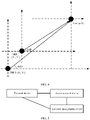
- a beam pattern (beam pattern) may be formed by traversing values of the AoD, as shown in a left diagram in FIG. 3 .
- the AoD is 30 degrees
- beam gains obtained through measurement at a beam#1, a beam#2, and a beam#3 are -11 dB, -5.3 dB, and 9 dB respectively.
- normalization processing may be performed on the beam gains. As shown in a right diagram in FIG.
- relative gains of the three beams after the normalization processing may be considered as a relative gain envelope when the AoD is 30 degrees.
- a maximum likelihood (maximum likelihood) algorithm may be used to select an angle that best matches the relative gain envelope (equivalent to a prestored angle fingerprint database) to estimate a corresponding AoD value.
- the beam gain may be, for example, reference signal received power (reference signal received power, RSRP).
- FIG. 4 is a schematic diagram of the DL-AOD positioning method in a two-dimensional plane.
- the assistance data used to perform location calculation includes spatial direction information of a PRS resource, such as an azimuth, an elevation, or a beam width.
- a PRS resource such as an azimuth, an elevation, or a beam width.
- only a coarse-grained angle range can be provided based on the assistance information in the solution, and high-accuracy positioning cannot be implemented.
- new assistance data needs to be designed for accurate angle estimation.
- LTE long term evolution
- FDD frequency division duplex
- TDD time division duplex
- UMTS universal mobile telecommunications system
- WiMAX worldwide interoperability for microwave access
- 5G future 5th generation
- new radio new radio
- the 5G mobile communications system used in this application includes a 5G mobile communications system with non-standalone (non-standalone, NSA) networking or a 5G mobile communications system with standalone (standalone, SA) networking.
- the technical solutions provided in this application are further applicable to a future communications system, for example, a 6th generation mobile communications system.
- the communications system may be a public land mobile network (public land mobile network, PLMN), a device-to-device (device-to-device, D2D) communications system, a machine-to-machine (machine to machine, M2M) communications system, an Internet of things (Internet of Things, IoT) communications system, or another communications system.
- PLMN public land mobile network
- D2D device-to-device
- M2M machine-to-machine
- IoT Internet of things
- FIG. 5 is a schematic diagram of an architecture of a positioning system to which a positioning method according to an embodiment of this application is applied.
- the positioning system includes a terminal device, one or more access network devices (one access network device is used as an example for illustration in FIG. 5 ), and a location management device.
- the terminal device, the access network device, and the location management device may directly communicate with each other, or may communicate with each other through forwarding by another device. This is not specifically limited in this embodiment of this application.
- the positioning system may further include another network element such as a mobility management network element. This is not specifically limited in this embodiment of this application.
- the location management device obtains a plurality of assistance data from the one or more access network devices, where each of the plurality of assistance data includes one or more groups of mapping relationships corresponding to one or more preset angles, each of the one or more groups of mapping relationships corresponds to one of the one or more preset angles, and each group of mapping relationships includes a mapping relationship between each of one or more PRS resource identifiers and power information corresponding to each PRS resource identifier at a corresponding preset angle; the location management device obtains, from a terminal device, power information corresponding to one or more PRS resource identifiers at each of a plurality of to-be-measured angles; and further, the location management device positions the terminal device based on the plurality of assistance data and the power information corresponding to the one or more PRS resource identifiers at each of the plurality of to-be-measured angles at the corresponding to-be-measured angle.
- the assistance data in this embodiment of this application includes the one or more groups of mapping relationships corresponding to the one or more preset angles, each of the one or more groups of mapping relationships corresponds to one of the one or more preset angles, and each group of mapping relationships includes the mapping relationship between each of the one or more PRS resource identifiers and the power information corresponding to each PRS resource identifier at the corresponding preset angle.
- the location management device can accurately estimate a to-be-measured angle (for example, an angle of departure or an angle of arrival) based on the plurality of assistance data and the power information corresponding to the one or more PRS resource identifiers at each of the plurality of to-be-measured angles at the corresponding to-be-measured angle, and can further implement high-accuracy positioning.
- a to-be-measured angle for example, an angle of departure or an angle of arrival
- the location management device in this embodiment of this application may be an LMF network element or a location management component (location management component, LMC) network element, or may be a local location management function (local location management function, LLMF) network element located in a network device.
- LMC location management component
- LLMF local location management function
- a 5G mobile communications system is used as an example.
- a network element or an entity corresponding to the access network device in FIG. 5 may be a next-generation radio access network (next-generation radio access network, NG-RAN) device in the 5G mobile communications system.
- the network element or entity corresponding to the mobility management network element may be an access and mobility management function (access and mobility management function, AMF) network element in the 5G mobile communications system. This is not specifically limited in this embodiment of this application.
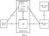
- FIG. 6 is a schematic diagram of an architecture of a positioning system to which a positioning method according to an embodiment of this application is applied in a 5G mobile communications system.
- a terminal device is connected to a radio access network through a next-generation evolved NodeB (next-generation evolved NodeB, ng-eNB) and a next-generation NodeB (generation NodeB, gNB) respectively by using an LTE-Uu interface and/or an NR-Uu interface.
- the radio access network is connected to a core network through an AMF network element by using an NG-C interface.
- the NG-RAN includes one or more ng-eNBs (one ng-eNB is used as an example for illustration in FIG.
- the NG-RAN may include one or more gNBs (one gNB is used as an example for illustration in FIG. 6 ).
- the NG-RAN may include one or more ng-eNBs and one or more gNBs.
- the ng-eNB is an LTE base station that accesses a 5G core network
- the gNB is a 5G base station that accesses the 5G core network.
- the core network includes an AMF network element and an LMF network element.
- the AMF network element is configured to implement functions such as access management.
- the LMF network element is configured to implement functions such as positioning or positioning assistance.
- the AMF network element is connected to the LMF network element by using an NLs interface.
- FIG. 7 is a schematic diagram of an architecture of another positioning system to which a positioning method according to an embodiment of this application is applied in a 5G mobile communications system.
- a difference between the architectures of the positioning systems in FIG. 7 and FIG. 6 lies in that a location management function apparatus or component (for example, an LMF network element) in FIG. 6 is deployed in a core network, but a location management function apparatus or component (for example, an LMC network element) in FIG. 7 may be deployed in an NG-RAN device.
- a gNB includes an LMC network element.
- the LMC network element is a part of a functional component of an LMF network element, and may be integrated into the gNB of the NG-RAN device.
- the device or function node included in the positioning system in FIG. 6 or FIG. 7 is merely an example for description, and does not constitute a limitation on the embodiments of this application.
- the positioning system in FIG. 6 or FIG. 7 may further include another network element, device, or function node that has an interaction relationship with the device or function node shown in the figure. This is not specifically limited herein.
- the terminal device (terminal equipment) in the embodiments of this application may be an access terminal, a subscriber unit, a subscriber station, a mobile station, a mobile station, a relay station, a remote station, a remote terminal, a mobile device, a user terminal (user terminal), UE, a terminal (terminal), a wireless communications device, a user agent, a user apparatus, a cellular phone, a cordless phone, a session initiation protocol (session initiation protocol, SIP) phone, a wireless local loop (wireless local loop, WLL) station, a personal digital assistant (personal digital assistant, PDA), a handheld device having a wireless communication function, a computing device or another processing device connected to a wireless modem, a vehicle-mounted device, a wearable device, a terminal device in a future 5G network, a terminal device in a future evolved PLMN, a terminal device in a future Internet of Vehicles, or the like. This is not limited in the embodiments of this application.
- the terminal may be a mobile phone, a tablet computer, a computer with a radio transceiver function, a virtual reality terminal device, an augmented reality terminal device, a wireless terminal in industrial control, a wireless terminal in unmanned driving, a wireless terminal in remote surgery, a wireless terminal in a smart grid, a wireless terminal in transportation safety, a wireless terminal in a smart city, or a wireless terminal in a smart home.
- the wearable device may also be referred to as a wearable intelligent device, and is a generic term for wearable devices such as glasses, gloves, watches, clothes, and shoes that are developed based on intelligent design of daily wearing by using wearable technologies.
- the wearable device is a portable device that can be directly worn on a body or integrated into clothes or an accessory of a user.
- the wearable device is not only a hardware device, but also implements a powerful function through software support, data exchange, and cloud interaction.
- wearable intelligent devices include full-featured and large-sized devices that can implement complete or partial functions without depending on smartphones, such as smart watches or smart glasses, and devices that focus on only one type of application function and need to work with other devices such as smartphones, such as various smart bands or smart jewelry for monitoring physical signs.
- the terminal device in the embodiments of this application may alternatively be a terminal device in an IoT system.
- IoT is an important part of future development of information technologies.
- a main technical feature of the IoT is connecting a thing to a network by using a communications technology, to implement an intelligent network for interconnection between a person and a machine or between things.
- an IoT technology may implement massive connections, deep coverage, and terminal power saving by using, for example, a narrowband (narrow band, NB) technology.
- NB narrowband
- the terminal device may further include a sensor, for example, an intelligent printer, a train detector, or a gas station.
- Main functions of the terminal device include: collecting data (for some terminal devices), receiving control information and downlink data of an access network device, sending electromagnetic waves, and transmitting uplink data to the access network device.
- the access network device in the embodiments of this application may be any communications device configured to communicate with the terminal device and having a radio transceiver function.
- the access network device includes but is not limited to an evolved NodeB (evolved NodeB, eNB), a baseband unit (baseband unit, BBU), an access point (access point, AP) in a wireless fidelity (wireless fidelity, Wi-Fi) system, a wireless relay node, a wireless backhaul node, a transmission point (transmission point, TP), a TRP, or the like.
- the access network device may be a gNB, a TRP, or a TP in a 5G system, or one antenna panel or a group of antenna panels (including a plurality of antenna panels) of a base station in a 5G system.
- the access network device may alternatively be a network node that constitutes a gNB or a TP, for example, a BBU or a distributed unit (distributed unit, DU).
- the gNB may include a centralized unit (centralized unit, CU) and a DU.
- the gNB may further include an active antenna unit (active antenna unit, AAU).
- the CU implements some functions of the gNB
- the DU implements some functions of the gNB.
- the CU is responsible for processing a non-real-time protocol and service, and implements functions of a radio resource control (radio resource control, RRC) layer and a packet data convergence protocol (packet data convergence protocol, PDCP) layer.
- RRC radio resource control
- PDCP packet data convergence protocol
- the DU is responsible for processing a physical layer protocol and a real-time service, and implements functions of a radio link control (radio link control, RLC) layer, a media access control (media access control, MAC) layer, and a physical (physical, PHY) layer.
- RLC radio link control
- MAC media access control
- PHY physical (physical, PHY) layer.
- the AAU implements some physical layer processing functions, radio frequency processing, and a function related to an active antenna.
- Information at the RRC layer is eventually converted into information at the PHY layer, or is converted from information at the PHY layer. Therefore, in this architecture, higher layer signaling such as RRC layer signaling may also be considered as being sent by the DU or sent by the DU and the AAU.
- the access network device may be a device including one or more of a CU node, a DU node, and an AAU node.
- communication between the access network device and the terminal device may be performed by using a licensed spectrum, communication may be performed by using an unlicensed spectrum, or communication may be performed by using both a licensed spectrum and an unlicensed spectrum.
- the access network device and the terminal device may communicate with each other by using a spectrum below 6 gigahertz (gigahertz, GHz), or may communicate with each other by using a spectrum above 6 GHz, or may communicate with each other by using both a spectrum below 6 GHz and a spectrum above 6 GHz.
- Spectrum resources used between the access network device and the terminal device are not limited in the embodiments of this application.
- the terminal device, the access network device, or the location management device in the embodiments of this application may be deployed on land, for example, in an indoor, outdoor, handheld, or vehicle-mounted application scenario, or may be deployed on water, or may be deployed on an airplane, a balloon, or a satellite in the air.
- An application scenario of the terminal device, the access network device, or the location management device is not limited in the embodiments of this application.
- the terminal device, the access network device, or the location management device includes a hardware layer, an operating system layer that runs on the hardware layer, and an application layer that runs on the operating system layer.
- the hardware layer includes hardware such as a central processing unit (central processing unit, CPU), a memory management unit (memory management unit, MMU), and a memory (also referred to as a main memory).
- the operating system may be any one or more computer operating systems that implement service processing through a process (process), for example, a Linux operating system, a Unix operating system, an Android operating system, an iOS operating system, or a Windows operating system.
- the application layer includes applications such as a browser, a contact list, word processing software, and instant messaging software.
- the embodiments of this application do not particularly limit a specific structure of an execution body of the method provided in the embodiments of this application, as long as communication can be performed according to the method provided in the embodiments of this application by running a program that records code of the method provided in the embodiments of this application.
- the execution body of the method provided in the embodiments of this application may be the terminal device, the access network device, or the location management device, or a functional module that is in the terminal device, the access network device, or the location management device and capable of invoking the program and executing the program.
- related functions of the terminal device, the access network device, or the location management device in the embodiments of this application may be implemented by one device, or may be implemented by a plurality of devices together, or may be implemented by one or more functional modules in one device.
- This is not specifically limited in the embodiments of this application.
- the foregoing function may be a network element on a hardware device, or may be a software function running on dedicated hardware, or may be a combination of hardware and software, or may be a virtualization function instantiated on a platform (for example, a cloud platform).
- FIG. 8 is a schematic diagram of a structure of a communications apparatus 800 according to an embodiment of this application.
- the communications apparatus 800 includes one or more processors 801, a communications line 802, and at least one communications interface (in FIG. 8 , only an example in which a communications interface 804 and one processor 801 are included is used for description).
- the communications apparatus 800 may further include a memory 803.
- the processor 801 may be a CPU, a microprocessor, an application-specific integrated circuit (application-specific integrated circuit, ASIC), or one or more integrated circuits configured to control program execution in the solution of this application.
- ASIC application-specific integrated circuit
- the communications line 802 may include a path for connecting different components.
- the communications interface 804 may be a transceiver module configured to communicate with another device or a communications network, for example, the Ethernet, a RAN, or a wireless local area network (wireless local area network, WLAN).
- the transceiver module may be an apparatus such as a transceiver or a transceiver machine.
- the communications interface 804 may alternatively be a transceiver circuit located in the processor 801, to implement signal input and signal output of the processor.
- the memory 803 may be an apparatus having a storage function.
- the memory may be a read-only memory (read-only memory, ROM) or another type of static storage device that can store static information and instructions, a random access memory (random access memory, RAM) or another type of dynamic storage device that can store information and instructions, an electrically erasable programmable read-only memory (electrically erasable programmable read-only memory, EEPROM), a compact disc read-only memory (compact disc read-only memory, CD-ROM) or another optical disk storage, an optical disc storage (including a compact disc, a laser disc, an optical disc, a digital versatile disc, a Blu-ray disc, and the like), a disk storage medium or another magnetic storage device, or any other medium that can be used to carry or store expected program code in a form of an instruction or a data structure and that can be accessed by a computer.
- the memory may stand alone and is connected to the processor through the communications line 802.
- the memory may alternatively be integrated with
- the memory 803 is configured to store computer-executable instructions for executing the solution of this application, and the processor 801 controls execution of the computer-executable instructions.
- the processor 801 is configured to execute the computer-executable instructions stored in the memory 803, to implement the positioning method provided in the embodiments of this application.
- the processor 801 may execute processing-related functions in a positioning method provided in the following embodiments of this application, and the communications interface 804 is responsible for communicating with another device or a communications network. This is not specifically limited in this embodiment of this application.
- the computer-executable instructions in this embodiment of this application may also be referred to as application program code. This is not specifically limited in this embodiment of this application.
- the processor 801 may include one or more CPUs, for example, a CPU 0 and a CPU 1 in FIG. 8 .
- the communications apparatus 800 may include a plurality of processors, for example, the processor 801 and a processor 808 in FIG. 8 .
- Each of the processors may be a single-core (single-CPU) processor or a multi-core (multi-CPU) processor.
- the processor herein may refer to one or more devices, circuits, and/or processing cores configured to process data (for example, computer program instructions).
- the communications apparatus 800 may further include an output device 805 and an input device 806.
- the output device 805 communicates with the processor 801, and may display information in a plurality of manners.
- the communications apparatus 800 may be a general-purpose apparatus or a dedicated apparatus.
- the communications apparatus 800 may be a desktop computer, a portable computer, a network server, a personal digital assistant (personal digital assistant, PDA), a mobile phone, a tablet computer, a wireless terminal device, an embedded device, or a device having a structure similar to that in FIG. 8 .
- a type of the communications apparatus 800 is not limited in this embodiment of this application.
- names of messages between network elements, names of parameters in the messages, or the like in the following embodiments of this application are merely examples, and there may be other names in a specific implementation. This is not specifically limited in embodiments of this application.
- assistance data added in the embodiments of this application relative to assistance data in an existing positioning method is described as follows:
- the assistance data includes one or more groups of mapping relationships corresponding to one or more preset angles, each of the one or more groups of mapping relationships corresponds to one of the one or more preset angles, and each group of mapping relationships includes a mapping relationship between each of one or more PRS resource identifiers and power information corresponding to each PRS resource identifier at a corresponding preset angle.
- a form of the assistance data may be shown in Table 1.
- Table 1 Angle PRS resource identifier Power info AOD#1 ID1 Power information corresponding to an ID1_#1 ID2 Power information corresponding to an ID2_#1 ID3 Power information corresponding to an ID3_#1 ⁇ ⁇
- the power information corresponding to each PRS resource identifier at the corresponding preset angle includes a power value corresponding to each PRS resource identifier at the corresponding preset angle.
- the power value in the embodiments of this application may be a power value obtained through actual measurement, or may be a power value after normalization processing is performed on a power value obtained through actual measurement to eliminate an unknown path loss.
- This is centrally described herein, and not specifically limited in the embodiments of this application.
- For a manner of performing normalization processing on the power value obtained through actual measurement to eliminate the unknown path loss refer to the conventional technology. Details are not described herein.
- the power value in the embodiments of this application includes a radiated power value, a received power value, or another power value.
- the radiated power value or the received power value may be, for example, an RSRP value, reference signal received quality (reference signal received quality, RSRQ), a received signal strength indicator (received signal strength indicator, RSSI), or a signal to interference plus noise ratio or signal to noise ratio (signal to interference noise ratio or signal to noise ratio, SINR/SNR).
- RSRQ reference signal received quality
- RSSI received signal strength indicator
- SINR/SNR signal to interference plus noise ratio or signal to noise ratio
- the power information corresponding to each PRS resource identifier at the corresponding preset angle includes a value obtained after the power value corresponding to each PRS resource identifier at the corresponding preset angle is compressed. In this manner, because the power value corresponding to each PRS resource identifier at the corresponding preset angle is compressed, signaling overheads can be reduced during transmission of the assistance data, and a positioning latency and power consumption can be reduced.
- a plurality of methods are available for compressing the power value corresponding to each PRS resource identifier at the corresponding preset angle.
- two compression methods are provided as examples: a lossless compression method and a lossy compression method.
- the lossless compression method may include the following two compression scenarios.
- the power information corresponding to each PRS resource identifier at the corresponding preset angle includes a value relative to a reference first power value, for the power value corresponding to each PRS resource identifier at the corresponding preset angle.
- the first power value is a largest one of power values corresponding to the one or more PRS resource identifiers at the corresponding preset angle. In other words, the first power value is a largest value obtained after the power values corresponding to the one or more PRS resource identifiers at the corresponding preset angle are sorted at the corresponding preset angle.
- the value relative to the reference first power value, for the power value corresponding to each PRS resource identifier at the corresponding preset angle, may be implemented by using the following difference method or quotient method.
- power values corresponding to all PRS resource identifiers at the corresponding preset angle are first sorted (for example, the power values may be in ascending order or descending order); and then by using a largest one (that is, the foregoing first power value) of the power values corresponding to the one or more PRS resource identifiers at the corresponding preset angle as a reference, subtraction is performed between the first power value and the power value corresponding to each PRS resource identifier at the corresponding preset angle to obtain a difference (rounded to an integer), where the difference may be used as the power information corresponding to each PRS resource identifier at the corresponding preset angle.
- Table 3 is described by using an example in which the power value corresponding to each PRS resource identifier at the corresponding preset angle is subtracted from the first power value.
- the first power value may alternatively be subtracted from the power value corresponding to each PRS resource identifier at the corresponding preset angle, and a result is shown in Table 4. This is not specifically limited in the embodiments of this application.
- power values corresponding to all PRS resource identifiers at the corresponding preset angle are first sorted (for example, the power values may be in ascending order or descending order); and then by using a largest one (that is, the foregoing first power value) of the power values corresponding to the one or more PRS resource identifiers at the corresponding preset angle as a reference, division is performed between the first power value and the power value corresponding to each PRS resource identifier at the corresponding preset angle, to obtain a quotient and a remainder (rounded to integers), where the quotient and the remainder may be used as the power information corresponding to each PRS resource identifier at the corresponding preset angle.
- Table 5 is described by using an example in which the first power value is divided by the power value corresponding to each PRS resource identifier at the corresponding preset angle.
- the power value corresponding to each PRS resource identifier at the corresponding preset angle may alternatively be divided by the first power value. This is not specifically limited in the embodiments of this application.
- the power information corresponding to each PRS resource identifier at the corresponding preset angle includes a value relative to a reference second power value, for the power value corresponding to each PRS resource identifier at the corresponding preset angle.
- the second power value is a largest one of power values corresponding to different PRS resource identifiers at the one or more preset angles at the corresponding preset angle. In other words, the second power value is a largest value obtained after the power values corresponding to the one or more PRS resource identifiers at the corresponding preset angle are sorted at all preset angles.
- the value relative to the reference second power value, for the power value corresponding to each PRS resource identifier at the corresponding preset angle, may be implemented by using the following difference method or quotient method.
- power values corresponding to different PRS resource identifiers at the one or more preset angles at the corresponding preset angle are first sorted (for example, the power values may be in ascending order or descending order); and then by using a largest one (that is, the foregoing second power value) of the power values corresponding to the different PRS resource identifiers at the one or more angles at the corresponding preset angle as a reference, subtraction is performed between the second power value and the power value corresponding to each PRS resource identifier at the corresponding preset angle to obtain a difference (rounded to an integer), where the difference may be used as the power information corresponding to each PRS resource identifier at the corresponding preset angle.
- a largest one that is, the foregoing second power value
- Table 6 is described by using an example in which the power value corresponding to each PRS resource identifier at the corresponding preset angle is subtracted from the second power value.
- the second power value may alternatively be subtracted from the power value corresponding to each PRS resource identifier at the corresponding preset angle. This is not specifically limited in the embodiments of this application.
- power values corresponding to different PRS resource identifiers at the one or more preset angles at the corresponding preset angle are first sorted (for example, the power values may be in ascending order or descending order); and then by using a largest one (that is, the foregoing second power value) of the power values corresponding to the different PRS resource identifiers at the one or more angles at the corresponding preset angle as a reference, division is performed between the second power value and the power value corresponding to each PRS resource identifier at the corresponding preset angle to obtain a quotient and a remainder (rounded to integers), where the quotient and the remainder may be used as the power information corresponding to each PRS resource identifier at the corresponding preset angle.
- Table 7 is described by using an example in which the second power value is divided by the power value corresponding to each PRS resource identifier at the corresponding preset angle.
- the power value corresponding to each PRS resource identifier at the corresponding preset angle may alternatively be divided by the second power value. This is not specifically limited in the embodiments of this application.
- the lossy compression method may include the following two compression scenarios.
- the power information corresponding to each PRS resource identifier at the corresponding preset angle includes a value relative to a reference previous power value, for the power value corresponding to each PRS resource identifier at the corresponding preset angle.
- Power values corresponding to the one or more PRS resource identifiers at the corresponding preset angle are sorted in ascending order or descending order. In other words, the power values corresponding to the one or more PRS resource identifiers at the corresponding preset angle are sorted at the corresponding preset angle.
- the value relative to the reference previous power value, for the power value corresponding to each PRS resource identifier at the corresponding preset angle, may be implemented by using the following differential method or differential quotient method.
- power values corresponding to all PRS resource identifiers at the corresponding preset angle are first sorted (for example, the power values may be in ascending order or descending order); and then subtraction is performed between a previous power value and a next power value to obtain a difference (rounded to an integer), where the difference may be used as the power information corresponding to each PRS resource identifier at the corresponding preset angle.
- the previous power value may be a compressed power value.
- the power information 3 corresponding to the ID2 is not obtained by directly subtracting a third power value (5.6) from a second power value (9.5), but obtained by directly subtracting the third power value (5.6) from a compressed second power value (9). This is centrally described herein, and not described again later.
- Table 8 is described by using an example in which the next power value is subtracted from the previous power value after the power values are sorted in descending order.
- the previous power value may alternatively be subtracted from the next power value after the power values are sorted in descending order.
- the next power value may be subtracted from the previous power value after the power values are sorted in ascending order.
- the previous power value may be subtracted from the next power value after the power values are sorted in ascending order. This is not specifically limited in the embodiments of this application.
- power values corresponding to all PRS resource identifiers at the corresponding preset angle are first sorted (for example, the power values may be in ascending order or descending order); and then subtraction is performed between a previous power value and a next power value to obtain a quotient and a remainder (rounded to integers), where the quotient and the remainder may be used as the power information corresponding to each PRS resource identifier at the corresponding preset angle.
- Table 9 is described by using an example in which the previous power value is divided by the next power value after the power values are sorted in descending order. Certainly, the next power value may be divided by the previous power value after the power values are sorted in descending order. Alternatively, the previous power value may be divided by the next power value after the power values are sorted in ascending order. Alternatively, the next power value may be divided by the previous power value after the power values are sorted in ascending order. This is not specifically limited in the embodiments of this application.
- the power information corresponding to each PRS resource identifier at the corresponding preset angle includes a value relative to a reference previous power value, for the power value corresponding to each PRS resource identifier at the corresponding preset angle.
- Power values corresponding to different PRS resource identifiers at the one or more preset angles at the corresponding preset angle are sorted in ascending order or descending order. In other words, the power values corresponding to the one or more PRS resource identifiers at the corresponding preset angle are sorted at all preset angles.
- the value relative to the reference previous power value, for the power value corresponding to each PRS resource identifier at the corresponding preset angle, may be implemented by using the following differential method or differential quotient method.
- power values corresponding to different PRS resource identifiers at the one or more preset angles at the corresponding preset angle are first sorted (for example, the power values may be in ascending order or descending order); and then subtraction is performed between a previous power value and a next power value to obtain a difference (rounded to an integer), where the difference may be used as the power information corresponding to each PRS resource identifier at the corresponding preset angle.
- Table 10 is described by using an example in which the next power value is subtracted from the previous power value after the power values are sorted in descending order.
- the previous power value may alternatively be subtracted from the next power value after the power values are sorted in descending order.
- the next power value may be subtracted from the previous power value after the power values are sorted in ascending order.
- the previous power value may be subtracted from the next power value after the power values are sorted in ascending order. This is not specifically limited in the embodiments of this application.
- power values corresponding to different PRS resource identifiers at the one or more preset angles at the corresponding preset angle are first sorted (for example, the power values may be in ascending order or descending order); and then division is performed between a previous power value and a next power value to obtain a quotient and a remainder (rounded to integers), where the quotient and the remainder may be used as the power information corresponding to each PRS resource identifier at the corresponding preset angle.
- Table 11 is described by using an example in which the previous power value is divided by the next power value after the power values are sorted in descending order. Certainly, the next power value may be divided by the previous power value after the power values are sorted in descending order. Alternatively, the previous power value may be divided by the next power value after the power values are sorted in ascending order. Alternatively, the next power value may be divided by the previous power value after the power values are sorted in ascending order. This is not specifically limited in the embodiments of this application.
- an order of presentation of each group of mapping relationships in the assistance data should also be based on a power value sorting result.
- the order of presentation of each group of mapping relationships in the assistance data during transmission may be shown in Table 12. Therefore, it is convenient to sequentially restore the power value corresponding to each PRS resource identifier at the corresponding preset angle. This is centrally described herein, and not described again later.
- each compression method may be used for a plurality of times or may be used in combination with other compression methods.
- the differential method or the differential quotient method is applicable to a case in which a difference between values is relatively large. Because a smaller compressed value can be obtained in this way, signaling overheads are reduced to a greater extent.
- the first power value may not need to be transmitted during transmission of the assistance data.
- a positioning device for example, an LMF network element in the following embodiments of this application
- the second power value needs to be transmitted during transmission of the assistance data. This is because when determining power information corresponding to one or more PRS resource identifiers at each of a plurality of to-be-measured angles, a positioning device needs to determine the power information by referring to the second power value; or a positioning device needs to restore, at all to-be-measured angles based on the second power value, power values corresponding to the PRS resource identifiers at the corresponding to-be-measured angle. This is not specifically limited in the embodiments of this application.
- the one or more PRS resource identifiers included in each group of mapping relationships are PRS resource identifiers of all PRS resources that need to be measured at the corresponding preset angle.
- the one or more PRS resource identifiers included in each group of mapping relationships are PRS resource identifiers of some PRS resources that need to be measured at the corresponding preset angle.
- the one or more PRS resource identifiers included in each group of mapping relationships are PRS resource identifiers of all PRS resources that need to be measured at the corresponding preset angle
- the one or more PRS resource identifiers included in each group of mapping relationships are PRS resource identifiers of some PRS resources that need to be measured at the corresponding preset angle. Therefore, signaling overheads can be reduced during transmission of the assistance data, and the positioning latency and power consumption can be reduced.
- the one or more PRS resource identifiers included in each group of mapping relationships are PRS resource identifiers of some PRS resources that need to be measured at the corresponding preset angle
- the one or more PRS resource identifiers included in each group of mapping relationships are PRS resource identifiers of all PRS resources that need to be measured at the corresponding preset angle, accuracy of angle estimation can be improved, and the positioning accuracy is improved to a greater extent.
- some PRS resources include PRS resources corresponding to first M power values after the sorting, where M is a positive integer greater than 1.
- the assistance data provided in the embodiments of this application may be shown in Table 13.
- Table 13 Angle PRS resource identifier Power value AOD#1 2° ID4 12.1 ID1 9.5 ID2 5.6
- AOD#2 4° ID2 11.5 ID4 6.7 ID1 4.1
- the assistance data provided in the embodiments of this application is values obtained by compressing the first M power values obtained after the power values corresponding to the PRS resource identifiers of all PRS resources that need to be measured at the corresponding preset angle are sorted in descending order.
- the positioning method includes the following steps.
- An NG-RAN device establishes assistance data, where the assistance data includes one or more groups of mapping relationships corresponding to one or more angles.
- the NG-RAN device may obtain, from a terminal device, a power value corresponding to each of one or more PRS resource identifiers at one or more preset angles, and establish the assistance data based on the power value corresponding to each of the one or more PRS resource identifiers at the one or more preset angles.
- a power value corresponding to a PRS resource identifier at a preset angle may be an average value of power values obtained by the NG-RAN device from different terminal devices and corresponding to the PRS resource identifier at the preset angle, or may be a power value obtained by the NG-RAN device from a terminal device and corresponding to the PRS resource identifier at the preset angle. This is not specifically limited in this embodiment of this application.
- the power value corresponding to each of the one or more PRS resource identifiers at the one or more preset angles may be shown in the foregoing Table 2.
- each PRS resource identifier in the one or more groups of mapping relationships at a corresponding preset angle includes a power value corresponding to each PRS resource identifier at the corresponding preset angle
- that the NG-RAN device establishes the assistance data based on the power value corresponding to each of the one or more PRS resource identifiers at the one or more preset angles specifically includes: the NG-RAN device establishes the one or more groups of mapping relationships corresponding to the one or more preset angles, where each of the one or more groups of mapping relationships corresponds to one of the one or more preset angles, and each group of mapping relationships includes a mapping relationship between each of the one or more PRS resource identifiers and a power value corresponding to each PRS resource identifier at a corresponding preset angle.
- each PRS resource identifier in the one or more groups of mapping relationships at a corresponding preset angle includes a value obtained after a power value corresponding to each PRS resource identifier at the corresponding preset angle is compressed
- that the NG-RAN device establishes the assistance data based on the power value corresponding to each of the one or more PRS resource identifiers at the one or more preset angles specifically includes: the NG-RAN device first compresses, by using the data compression method provided in the foregoing embodiment, the power value corresponding to each PRS resource identifier at the corresponding preset angle, and further establishes one or more groups of mapping relationships corresponding to the one or more preset angles, where each of the one or more groups of mapping relationships corresponds to one of the one or more preset angles, and each group of mapping relationships includes a mapping relationship between each of the one or more PRS resource identifiers and the value obtained after the power value corresponding to each PRS resource identifier at the corresponding preset angle is compressed.
- the NG-RAN device may periodically update the assistance data.
- the assistance data is updated based on power values recently obtained from different terminal devices and corresponding to each of the one or more PRS resource identifiers at the one or more preset angles. Because the assistance data is periodically updated, accuracy of the assistance data can be ensured, and further, accuracy of subsequently estimating a to-be-measured angle can be improved, and positioning accuracy is improved to a greater extent.
- step S901 in this embodiment of this application may be considered as an offline part, that is, a step performed before a positioning procedure of a terminal device is started. This is not specifically limited in this embodiment of this application.
- a positioning procedure may be initiated by performing the following step S902a, S902b, or S902c.
- the terminal device sends a positioning request to an AMF network element.
- the AMF network element receives the positioning request from the terminal device.
- the positioning request is used to request to position the terminal device.
- the terminal device may actively initiate a procedure for positioning the terminal device.
- a 5G core (5G core, 5GC) location services (location services, LCS) entity sends a positioning request to the AMF network element.
- the AMF network element receives the positioning request 2 from the terminal device.
- the positioning request is used to request to position the terminal device.
- the 5GC LCS entity may initiate a procedure for positioning the terminal device.
- the 5GC LCS entity in this embodiment of this application may be, for example, a gateway mobile location center (gateway mobile location center, GMLC).
- GMLC gateway mobile location center
- S902c Determine some positioning service requirements of the terminal device (for example, the terminal device needs an emergency call), and triggers a positioning request by itself.
- the AMF network element may initiate a procedure for positioning the terminal device.
- the positioning method provided in this embodiment of this application further includes the following steps S903 to S909.
- the AMF network element sends a positioning request to an LMF network element.
- the LMF network element receives the positioning request from the AMF network element.
- the positioning request is used to request to position the terminal device.
- the LMF network element sends an LTE positioning protocol (LTE positioning protocol, LPP) message 1 to the terminal device.
- LPP LTE positioning protocol
- the terminal device receives the LPP message 1 from the LMF network element.
- the LPP message 1 is used to request a positioning capability of the terminal device.
- the LPP message 1 in this embodiment of this application may be, for example, an LPP request capabilities (LPP Request Capabilities) message.
- LPP Request Capabilities LPP Request Capabilities
- the terminal device sends an LPP message 2 to the LMF network element.
- the LMF network element receives the LPP message 2 from the terminal device.
- the LPP message 2 carries the positioning capability of the terminal device.
- the positioning capability of the terminal device may be, for example, a UE-assisted DL-time difference of arrival (time difference of arrival, TDOA) or a UE-assisted DL-AOD in UE-assisted positioning. This is not specifically limited in this embodiment of this application.
- the LPP message 2 in this embodiment of this application may be, for example, an LPP provide capabilities (LPP Provide Capabilities) message.
- LPP provide capabilities LPP Provide Capabilities
- the LMF network element sends an NR positioning protocol (NR positioning protocol annex, NRPPa) message 1 to the NG-RAN device.
- NRPPa NR positioning protocol annex
- the NG-RAN device receives the NRPPa message 1 from the LMF network element.
- the NRPPa message 1 is used to request positioning assistance data.
- the NRPPa message 1 in this embodiment of this application may be, for example, an NRPPa request assistance data (NRPPa Request Assistance Data) message.
- NRPPa Request Assistance Data NRPPa Request Assistance Data
- the NG-RAN device sends an NRPPa message 2 to the LMF network element.
- the LMF network element receives the NRPPa message 2 from the NG-RAN device.
- the NRPPa message 2 carries the assistance data provided by the NG-RAN device for the LMF network element.
- the NRPPa message 2 in this embodiment of this application may be, for example, an NRPPa provide assistance data (NRPPa Provide Assistance Data) message.
- NRPPa Provide Assistance Data NRPPa Provide Assistance Data
- the assistance data provided by the NG-RAN device for the LMF network element not only includes the one or more groups of mapping relationships corresponding to the one or more preset angles in the foregoing embodiment, but also includes some assistance data that can be provided by the NG-RAN device for the LMF network element for assisted positioning in the conventional technology, for example, location information of the NG-RAN device. This is not specifically limited in this embodiment of this application.
- the NG-RAN device may also actively send, to the LMF network element by using an NRPPa message, assistance data that can be provided by the NG-RAN device for the LMF network element. This is not specifically limited in this embodiment of this application.
- the LMF network element sends an LPP message 3 to the terminal device.
- the terminal device receives the LPP message 3 from the LMF network element.
- the LPP message 3 is used to request positioning assistance data.
- the LPP message 3 in this embodiment of this application may be, for example, an LPP request assistance data (LPP Request Assistance Data) message.
- LPP Request Assistance Data LPP Request Assistance Data
- the terminal device sends an LPP message 4 to the LMF network element.
- the LMF network element receives the LPP message 4 from the terminal device.
- the LPP message 4 carries the assistance data provided by the terminal device for the LMF network element.
- the LPP message 4 in this embodiment of this application may be, for example, an LPP provide assistance data (LPP Provide Assistance Data) message.
- LPP Provide Assistance Data LPP Provide Assistance Data
- the assistance data provided by the terminal device for the LMF network element may include, for example, physical cell IDs (physical cell IDs, PCIs), global cell IDs (global cell IDs, GCIs), and P IDs. This is not specifically limited in this embodiment of this application.
- the terminal device may actively provide the assistance data for the LMF network element. This is not specifically limited in this embodiment of this application.
- steps S901 to S909 merely provide an example of a procedure in which one access network device participates in the positioning method when the LMF network element obtains the assistance data.
- participation of a plurality of access network devices may be required.
- processing and an interaction procedure (not shown in FIG. 9A and FIG. 9B ) of each access network device refer to processing and the related interaction procedure of the NG-RAN device in the foregoing steps S901 to S909. Details are not described herein again.
- the positioning method provided in this embodiment of this application further includes the following steps S910 and S911.
- the terminal device determines power information corresponding to one or more PRS resource identifiers which correspond to each of a plurality of to-be-measured angles.
- that the terminal device determines power information corresponding to one or more PRS resource identifiers at each of a plurality of to-be-measured angles may include: the terminal device receives a reference signal from the NG-RAN device in FIG. 9A and FIG. 9B , and determines, based on the reference signal, power information corresponding to one or more PRS resource identifiers at a to-be-measured angle at the to-be-measured angle; and the terminal device may receive a reference signal from another access network device (not shown in FIG. 9A and FIG. 9B ), and determine, based on the reference signal, power information corresponding to one or more PRS resource identifiers at another to-be-measured angle at the another to-be-measured angle.
- the terminal device may determine, based on a reference signal, a power value corresponding to one or more PRS resource identifiers at a to-be-measured angle at the to-be-measured angle. Further, in a possible implementation, the terminal device may use the power value corresponding to the one or more PRS resource identifiers at the to-be-measured angle as power information corresponding to the one or more PRS resource identifiers at the to-be-measured angle.
- the terminal device may compress the power value corresponding to the one or more PRS resource identifiers at the to-be-measured angle, and use a value obtained after the power value corresponding to the one or more PRS resource identifiers at the to-be-measured angle is compressed, as power information corresponding to the one or more PRS resource identifiers at the to-be-measured angle.
- a corresponding compression method is consistent with that on the NG-RAN device side. Refer to the related description in the foregoing assistance data. Details are not described herein again.
- the one or more PRS resource identifiers included in each group of mapping relationships in the assistance data are PRS resource identifiers of all PRS resources that need to be measured at the corresponding preset angle
- the one or more PRS resource identifiers at each to-be-measured angle are PRS resource identifiers of all PRS resources that need to be measured at the corresponding to-be-measured angle
- the one or more PRS resource identifiers at each to-be-measured angle are PRS resource identifiers of some PRS resources that need to be measured at the corresponding to-be-measured angle.
- PRS resource identifiers of all PRS resources that need to be measured at the corresponding to-be-measured angle are sorted in descending order
- some PRS resources that need to be measured at the corresponding to-be-measured angle include PRS resources corresponding to first M power values after the sorting, where M is a positive integer greater than 1. This is centrally described herein, and not described again later.
- the LMF network element sends an LPP message 5 to the terminal device.
- the terminal device receives the LPP message 5 from the LMF network element.
- the LPP message 5 is used to request location information.
- the LPP message 5 in this embodiment of this application may be, for example, an LPP request location information (LPP Request Location Information) message.
- LPP Request Location Information LPP Request Location Information
- the terminal device sends an LPP message 6 to the LMF network element.
- the LMF network element receives the LPP message 6 from the terminal device.
- the LPP message 6 carries the power information corresponding to the one or more PRS resource identifiers at each of the plurality of to-be-measured angles at the corresponding to-be-measured angle.
- the LPP message 6 in this embodiment of this application may be, for example, an LPP provide location information (LPP Provide Location Information) message.
- LPP Provide Location Information LPP Provide Location Information
- the terminal device may actively provide the location information for the LMF network element. This is not specifically limited in this embodiment of this application.
- the LMF network element positions the terminal device based on the plurality of assistance data and the power information corresponding to the one or more PRS resource identifiers at each of the plurality of to-be-measured angles.
- the LMF network element positions the terminal device based on the plurality of assistance data and the power information corresponding to the one or more PRS resource identifiers at each of the plurality of to-be-measured angles at the corresponding to-be-measured angle may include: the LMF network element determines the plurality of to-be-measured angles based on the plurality of assistance data and the power information corresponding to the one or more PRS resource identifiers at each of the plurality of to-be-measured angles at the corresponding to-be-measured angle; and further, the LMF network element positions the terminal device based on the plurality of to-be-measured angles and location information of an access network device corresponding to each of the plurality of to-be-measured angles.
- a basis for positioning the terminal device may further include other assistance data obtained by the LMF network element, for example, physical cell IDs (physical cell IDs, PCIs), global cell IDs (global cell IDs, GCIs), TP IDs, and PRS configuration information. This is not specifically limited in this embodiment of this application.
- location information of the terminal device may be determined with reference to the foregoing formula (1). Details are not described herein again.
- both the terminal device and the NG-RAN device compress a power value corresponding to each PRS resource identifier at the corresponding preset or to-be-measured angle according to the method described in scenario 1 in the foregoing embodiment.
- Power information corresponding to each PRS resource identifier in the mapping relationship at the corresponding preset angle is shown in Table 3.
- Power information obtained by the terminal device and corresponding to one or more PRS resource identifiers at the to-be-measured angle at the corresponding to-be-measured angle is shown in Table 14.
- Table 14 PRS resource identifier Power info ID1 7.1 ID2 0 ID3 10 ID4 5
- any to-be-measured angle is an angle between a PRS resource (beam) of an access network device and a receive beam of the terminal device.
- the corresponding assistance data should be understood as assistance data established by using the access network device.
- the assistance data corresponding to the to-be-measured angle between the NG-RAN device and the terminal device in FIG. 9A and FIG. 9B is the assistance data established by using the NG-RAN device in FIG. 9A and FIG. 9B . This is centrally described herein, and not described again later.
- the foregoing steps S910 and S911 are described by using an example in which the terminal device determines the power information corresponding to the one or more PRS resource identifiers at each of the plurality of to-be-measured angles at the corresponding to-be-measured angle, and further, the LMF network element determines the plurality of to-be-measured angles based on the plurality of assistance data and the power information corresponding to the one or more PRS resource identifiers at each of the plurality of to-be-measured angles at the corresponding to-be-measured angle.
- the terminal device may determine a power value corresponding to the one or more PRS resource identifiers at each of the plurality of to-be-measured angles at the corresponding to-be-measured angle, and further, the LMF network element determines the plurality of to-be-measured angles based on the plurality of assistance data and the power value corresponding to the one or more PRS resource identifiers at each of the plurality of to-be-measured angles at the corresponding to-be-measured angle.
- the LMF network element may restore power information corresponding to one or more PRS resource identifiers included in the corresponding assistance data at the corresponding preset angle to a power value corresponding to the one or more PRS resource identifiers at the corresponding preset angle. Further, matching is performed between this power value and the power value corresponding to the one or more PRS resource identifiers at the to-be-measured angle at the corresponding to-be-measured angle, to determine the corresponding to-be-measured angle. This is not specifically limited in this embodiment of this application.
- the LMF network element may restore, based on a largest value (that is, the foregoing second power value) obtained after power values corresponding to the one or more PRS resource identifiers at the corresponding preset angle are sorted at all preset angles, the power information corresponding to the one or more PRS resource identifiers included in the corresponding assistance data at the corresponding preset angle to the power value corresponding to the one or more PRS resource identifiers at the corresponding preset angle, and further perform matching between this power value and the power value corresponding to the one or more PRS resource identifiers at the to-be-measured angle at the corresponding to-be-measured angle, to determine the corresponding to-be-measured angle.
- a largest value that is, the foregoing second power value
- the positioning method provided in this embodiment of this application further includes the following step S914.
- the LMF network element sends the location information of the terminal device to the AMF network element.
- the AMF network element receives the location information of the terminal device from the LMF network element.
- the positioning method provided in this embodiment of this application further includes the following step S915.
- the AMF network element sends the location information of the terminal device to the 5GC LCS entity.
- the 5GC LCS entity receives the location information of the terminal device from the AMF network element.
- the assistance data in this embodiment of this application includes the one or more groups of mapping relationships corresponding to the one or more preset angles, each of the one or more groups of mapping relationships corresponds to one of the one or more preset angles, and each group of mapping relationships includes the mapping relationship between each of the one or more PRS resource identifiers and the power information corresponding to each PRS resource identifier at the corresponding preset angle.
- the LMF network element can accurately estimate a to-be-measured angle based on the plurality of assistance data and the power information corresponding to the one or more PRS resource identifiers at each of the plurality of to-be-measured angles at the corresponding to-be-measured angle, and can further implement high-accuracy positioning.
- the processor 801 in the communications apparatus 800 shown in FIG. 8 may perform actions of the terminal device, the NG-RAN device, or the LMF network element in steps S901 to S915 by invoking the application program code stored in the memory 803.
- the method and/or step implemented by the location management device may also be implemented by a component (for example, a chip or a circuit) that can be used for the location management device; and the method and/or step implemented by the access network device may also be implemented by a component (for example, a chip or a circuit) that can be used for the access network device.
- an embodiment of this application further provides a communications apparatus, and the communications apparatus is configured to implement the foregoing methods.
- the communications apparatus may be the location management device in the foregoing method embodiment, or an apparatus including the location management device, or a component that can be used for the location management device; or the communications apparatus may be the access network device in the foregoing method embodiment, or an apparatus including the access network device, or a component that can be used for the access network device.
- the communications apparatus includes a corresponding hardware structure and/or software module for performing each function.
- the communications apparatus may be divided into functional modules based on the foregoing method embodiments.
- each functional module may be obtained through division based on each corresponding function, or two or more functions may be integrated into one processing module.
- the integrated module may be implemented in a form of hardware, or may be implemented in a form of a software functional module. It should be noted that, in embodiments of this application, division into the modules is an example, and is merely a logical function division. In actual implementation, another division manner may be used.
- FIG. 10 is a schematic diagram of a structure of a communications apparatus 100 according to an embodiment of this application.
- the communications apparatus 100 includes a transceiver module 1001 and a processing module 1002.
- the transceiver module 1001 may also be referred to as a transceiver unit, and is configured to implement a transceiver function.
- the transceiver module 1001 may be a transceiver circuit, a transceiver machine, a transceiver, or a communications interface.
- the transceiver module 1001 is configured to obtain a plurality of assistance data from one or more access network devices, where each of the plurality of assistance data includes one or more groups of mapping relationships corresponding to one or more preset angles, each of the one or more groups of mapping relationships corresponds to one of the one or more preset angles, and each group of mapping relationships includes a mapping relationship between each of one or more PRS resource identifiers and power information corresponding to each PRS resource identifier at a corresponding preset angle; the transceiver module 1001 is further configured to obtain, from a terminal device, power information corresponding to one or more PRS resource identifiers at each of a plurality of to-be-measured angles; and the processing module 1002 is configured to position the terminal device based on the plurality of assistance data and the power information corresponding to the one or more PRS resource identifiers at each of the plurality of to-be-measured angles at the corresponding to-
- the processing module 1002 is specifically configured to: determine the plurality of to-be-measured angles based on the plurality of assistance data and the power information corresponding to the one or more PRS resource identifiers at each of the plurality of to-be-measured angles at the corresponding to-be-measured angle; and position the terminal device based on the plurality of to-be-measured angles and location information of an access network device corresponding to each of the plurality of to-be-measured angles.
- the transceiver module 1001 is further configured to receive a positioning request from a mobility management network element, where the positioning request is used to request to position the terminal device; and the transceiver module 1001 is further configured to send location information of the terminal device to the mobility management network element.
- the processing module 1002 is configured to establish or update assistance data, where the assistance data includes one or more groups of mapping relationships corresponding to one or more preset angles, each of the one or more groups of mapping relationships corresponds to one of the one or more preset angles, and each group of mapping relationships includes a mapping relationship between each of one or more PRS resource identifiers and power information corresponding to each PRS resource identifier at a corresponding preset angle; and the transceiver module 1001 is configured to send the assistance data to a location management device.
- the transceiver module 1001 is further configured to receive a first request message from the location management device, where the first request message is used to request the assistance data.
- the corresponding power information includes a power value corresponding to each of the one or more PRS resource identifiers at the corresponding preset or to-be-measured angle.
- the corresponding power information includes a value obtained after the power value corresponding to each of the one or more PRS resource identifiers at the corresponding preset or to-be-measured angle is compressed.
- the corresponding power information includes a value relative to a reference first power value, for the power value corresponding to each of the one or more PRS resource identifiers at the corresponding preset or to-be-measured angle, where the first power value is a largest one of power values corresponding to the one or more PRS resource identifiers at the corresponding preset or to-be-measured angle.
- the corresponding power information includes a value relative to a reference previous power value, for the power value corresponding to each of the one or more PRS resource identifiers at the corresponding preset or to-be-measured angle, where power values corresponding to the one or more PRS resource identifiers at the corresponding preset or to-be-measured angle are sorted in ascending order or descending order.
- the power value includes a radiated power value or a received power value.
- the one or more PRS resource identifiers are PRS resource identifiers of all PRS resources that need to be measured at the corresponding preset or to-be-measured angle; or the one or more PRS resource identifiers are PRS resource identifiers of some PRS resources that need to be measured at the corresponding preset or to-be-measured angle.
- some PRS resources include PRS resources corresponding to first M power values after the sorting, where M is a positive integer greater than 1.
- the communications apparatus 100 is presented in a form of functional modules obtained through division in an integrated manner.
- the "module” herein may be a specific ASIC, a circuit, a processor and a memory that execute one or more software or firmware programs, an integrated logic circuit, and/or another component that may provide the foregoing functions.
- the processor 801 in the communications apparatus 800 shown in FIG. 8 may invoke the computer-executable instructions stored in the memory 803, so that the communications apparatus 800 performs the positioning method in the foregoing method embodiment.
- the processor 801 in the communications apparatus 800 shown in FIG. 8 may invoke the computer-executable instructions stored in the memory 803 to implement functions or implementation processes of the transceiver module 1001 and the processing module 1002 in FIG. 10 .
- the processor 801 in the communications apparatus 800 shown in FIG. 8 may invoke the computer-executable instructions stored in the memory 803 to implement functions or an implementation process of the processing module 1002 in FIG. 10
- the communications interface 804 in the communications apparatus 800 shown in FIG. 8 may implement functions or an implementation process of the transceiver module 1001 in FIG. 10 .
- the communications apparatus 100 provided in this embodiment may perform the positioning method in the foregoing method embodiment, for technical effects that can be achieved by the communications apparatus 100, refer to the foregoing method embodiment. Details are not described herein again.
- one or more of the foregoing modules or units may be implemented by using software, hardware, or a combination thereof.
- the software exists in a form of computer program instructions, and is stored in a memory.
- the processor may be configured to execute the program instructions to implement the foregoing method procedures.
- the processor may be integrated into an SoC (system-on-chip) or an ASIC, or may be an independent semiconductor chip.
- the processor may further include a necessary hardware accelerator, for example, a field programmable gate array (field programmable gate array, FPGA), a PLD (programmable logic device), or a logic circuit that implements a dedicated logic operation.
- the hardware may be any one of or any combination of a CPU, a microprocessor, a digital signal processing (digital signal processing, DSP) chip, a microcontroller unit (microcontroller unit, MCU), an artificial intelligence processor, an ASIC, an SoC, an FPGA, a PLD, a dedicated digital circuit, a hardware accelerator, or a non-integrated discrete device.
- the hardware may perform the foregoing method procedures with necessary software or without software.
- FIG. 11 is a schematic diagram of a structure of yet another communications apparatus 110 according to an embodiment of this application.
- the communications apparatus 110 includes a transceiver 1101 and a processor 1102.
- the transceiver 1101 is configured to obtain a plurality of assistance data from one or more access network devices, where each of the plurality of assistance data includes one or more groups of mapping relationships corresponding to one or more preset angles, each of the one or more groups of mapping relationships corresponds to one of the one or more preset angles, and each group of mapping relationships includes a mapping relationship between each of one or more PRS resource identifiers and power information corresponding to each PRS resource identifier at a corresponding preset angle; the transceiver 1101 is further configured to obtain, from a terminal device, power information corresponding to one or more PRS resource identifiers at each of a plurality of to-be-measured angles; and the processor 1102 is configured to position the terminal device based on the plurality of assistance data and the power information corresponding to the one or more PRS resource identifiers at each of the plurality of to-be-measured angles at the corresponding to-be-measure
- the processor 1102 is specifically configured to: determine the plurality of to-be-measured angles based on the plurality of assistance data and the power information corresponding to the one or more PRS resource identifiers at each of the plurality of to-be-measured angles at the corresponding to-be-measured angle; and position the terminal device based on the plurality of to-be-measured angles and location information of an access network device corresponding to each of the plurality of to-be-measured angles.
- the transceiver 1101 is further configured to receive a positioning request from a mobility management network element, where the positioning request is used to request to position the terminal device; and the transceiver 1101 is further configured to send location information of the terminal device to the mobility management network element.
- the processor 1102 is configured to establish or update assistance data, where the assistance data includes one or more groups of mapping relationships corresponding to one or more preset angles, each of the one or more groups of mapping relationships corresponds to one of the one or more preset angles, and each group of mapping relationships includes a mapping relationship between each of one or more PRS resource identifiers and power information corresponding to each PRS resource identifier at a corresponding preset angle; and the transceiver 1101 is configured to send the assistance data to a location management device.
- the transceiver 1101 is further configured to receive a first request message from the location management device, where the first request message is used to request the assistance data.
- the corresponding power information includes a power value corresponding to each of the one or more PRS resource identifiers at the corresponding preset or to-be-measured angle.
- the corresponding power information includes a value obtained after the power value corresponding to each of the one or more PRS resource identifiers at the corresponding preset or to-be-measured angle is compressed.
- the corresponding power information includes a value relative to a reference first power value, for the power value corresponding to each of the one or more PRS resource identifiers at the corresponding preset or to-be-measured angle, where the first power value is a largest one of power values corresponding to the one or more PRS resource identifiers at the corresponding preset or to-be-measured angle.
- the corresponding power information includes a value relative to a reference previous power value, for the power value corresponding to each of the one or more PRS resource identifiers at the corresponding preset or to-be-measured angle, where power values corresponding to the one or more PRS resource identifiers at the corresponding preset or to-be-measured angle are sorted in ascending order or descending order.
- the power value includes a radiated power value or a received power value.
- the one or more PRS resource identifiers are PRS resource identifiers of all PRS resources that need to be measured at the corresponding preset or to-be-measured angle; or the one or more PRS resource identifiers are PRS resource identifiers of some PRS resources that need to be measured at the corresponding preset or to-be-measured angle.
- some PRS resources include PRS resources corresponding to first M power values after the sorting, where M is a positive integer greater than 1.
- the communications apparatus 110 provided in this embodiment may perform the positioning method in the foregoing method embodiment, for technical effects that can be achieved by the communications apparatus 110, refer to the foregoing method embodiment. Details are not described herein again.
- an embodiment of this application further provides a system-on-chip, including at least one processor and an interface.
- the at least one processor is coupled to a memory by using the interface.
- the at least one processor executes a computer program or computer instructions in the memory, the method in any one of the foregoing method embodiments is performed.
- the system-on-chip may include a chip, or may include a chip and another discrete component. This is not specifically limited in this embodiment of this application.
- a, b, or c may indicate: a, b, c, a and b, a and c, b and c, or a, b, and c, where a, b, and c may be singular or plural.
- terms such as “first” and “second” are used in embodiments of this application to distinguish between same items or similar items that have basically same functions and purposes. A person skilled in the art may understand that the terms such as “first” and “second” do not limit a quantity and an execution sequence, and the terms such as “first” and “second” do not indicate a definite difference.
- example or “for example” is used to represent giving an example, an illustration, or a description. Any embodiment or solution described as “example” or “for example” in embodiments of this application is not to be construed as being more preferred or having more advantages than other embodiments or solutions. Exactly, use of the word such as “example” or “for example” is intended to present a related concept in a specific manner for ease of understanding.
- All or some of the foregoing embodiments may be implemented by using software, hardware, firmware, or any combination thereof.
- a software program is used to implement the embodiments, all or a part of the embodiments may be implemented in a form of a computer program product.
- the computer program product includes one or more computer instructions.
- the computer may be a general-purpose computer, a dedicated computer, a computer network, or another programmable apparatus.
- the computer instructions may be stored in a computer-readable storage medium or may be transmitted from a computer-readable storage medium to another computer-readable storage medium.
- the computer instructions may be transmitted from a website, computer, server, or data center to another website, computer, server, or data center in a wired (for example, a coaxial cable, an optical fiber, or a digital subscriber line (digital subscriber line, DSL)) or wireless (for example, infrared, radio, or microwave) manner.
- the computer-readable storage medium may be any usable medium accessible by a computer, or a data storage device, such as a server or a data center, integrating one or more usable media.
- the usable medium may be a magnetic medium (for example, a floppy disk, a hard disk, or a magnetic tape), an optical medium (for example, a DVD), a semiconductor medium (for example, a solid-state disk (solid-state disk, SSD)), or the like.
- a magnetic medium for example, a floppy disk, a hard disk, or a magnetic tape
- an optical medium for example, a DVD
- a semiconductor medium for example, a solid-state disk (solid-state disk, SSD)
Landscapes
- Engineering & Computer Science (AREA)
- Signal Processing (AREA)
- Computer Networks & Wireless Communication (AREA)
- Physics & Mathematics (AREA)
- General Physics & Mathematics (AREA)
- Radar, Positioning & Navigation (AREA)
- Remote Sensing (AREA)
- Mobile Radio Communication Systems (AREA)
- Position Fixing By Use Of Radio Waves (AREA)
Applications Claiming Priority (1)
| Application Number | Priority Date | Filing Date | Title |
|---|---|---|---|
| PCT/CN2019/130989 WO2021134729A1 (fr) | 2019-12-31 | 2019-12-31 | Procédé, appareil et système de positionnement |
Publications (2)
| Publication Number | Publication Date |
|---|---|
| EP4072167A1 true EP4072167A1 (fr) | 2022-10-12 |
| EP4072167A4 EP4072167A4 (fr) | 2022-10-26 |
Family
ID=76685811
Family Applications (1)
| Application Number | Title | Priority Date | Filing Date |
|---|---|---|---|
| EP19958166.1A Pending EP4072167A4 (fr) | 2019-12-31 | 2019-12-31 | Procédé, appareil et système de positionnement |
Country Status (6)
| Country | Link |
|---|---|
| US (1) | US20220334212A1 (fr) |
| EP (1) | EP4072167A4 (fr) |
| JP (1) | JP7521716B2 (fr) |
| CN (1) | CN114846822A (fr) |
| CA (1) | CA3163434A1 (fr) |
| WO (1) | WO2021134729A1 (fr) |
Families Citing this family (2)
| Publication number | Priority date | Publication date | Assignee | Title |
|---|---|---|---|---|
| CN117882399A (zh) * | 2022-08-12 | 2024-04-12 | 北京小米移动软件有限公司 | 定位方法、装置、基站、设备、存储介质及芯片 |
| CN118524345A (zh) * | 2023-02-17 | 2024-08-20 | 大唐移动通信设备有限公司 | 一种信息传输方法及装置 |
Family Cites Families (6)
| Publication number | Priority date | Publication date | Assignee | Title |
|---|---|---|---|---|
| CN101388700B (zh) | 2007-09-14 | 2012-09-26 | 中兴通讯股份有限公司 | 一种自适应选择信道质量指示信息压缩方式的方法和装置 |
| US10660109B2 (en) * | 2016-11-16 | 2020-05-19 | Qualcomm Incorporated | Systems and methods to support multiple configurations for positioning reference signals in a wireless network |
| US10736074B2 (en) | 2017-07-31 | 2020-08-04 | Qualcomm Incorporated | Systems and methods to facilitate location determination by beamforming of a positioning reference signal |
| CN109327901B (zh) * | 2017-08-01 | 2023-06-20 | 北京三星通信技术研究有限公司 | 分配定位资源的方法及设备 |
| CN109842437A (zh) * | 2017-11-29 | 2019-06-04 | 索尼公司 | 无线通信系统中的电子设备、方法和计算机可读存储介质 |
| CN110536234A (zh) * | 2019-08-13 | 2019-12-03 | 中兴通讯股份有限公司 | 位置信息确定方法、装置、第一终端及第二终端 |
-
2019
- 2019-12-31 CN CN201980103303.7A patent/CN114846822A/zh active Pending
- 2019-12-31 EP EP19958166.1A patent/EP4072167A4/fr active Pending
- 2019-12-31 JP JP2022540675A patent/JP7521716B2/ja active Active
- 2019-12-31 CA CA3163434A patent/CA3163434A1/fr active Pending
- 2019-12-31 WO PCT/CN2019/130989 patent/WO2021134729A1/fr unknown
-
2022
- 2022-06-30 US US17/854,274 patent/US20220334212A1/en active Pending
Also Published As
| Publication number | Publication date |
|---|---|
| US20220334212A1 (en) | 2022-10-20 |
| JP7521716B2 (ja) | 2024-07-24 |
| JP2023509044A (ja) | 2023-03-06 |
| EP4072167A4 (fr) | 2022-10-26 |
| WO2021134729A1 (fr) | 2021-07-08 |
| CA3163434A1 (fr) | 2021-07-08 |
| CN114846822A (zh) | 2022-08-02 |
Similar Documents
| Publication | Publication Date | Title |
|---|---|---|
| US20220334212A1 (en) | Positioning Method, Apparatus, and System | |
| EP3372024B1 (fr) | Positionnement dans des systèmes wlan | |
| US20210329416A1 (en) | Method and Apparatus for Location Services | |
| WO2021031714A1 (fr) | Procédé et appareil de positionnement basé sur angle relatif | |
| WO2021227901A1 (fr) | Procédé de positionnement, appareil de gestion de positionnement, dispositif de réseau d'accès et terminal | |
| CN110036307A (zh) | 一种定位方法、系统及相关设备 | |
| WO2020207096A1 (fr) | Procédé pour effectuer un positionnement dans des scénarios 5g, plate-forme de positionnement et terminal utilisateur | |
| US12015965B2 (en) | Apparatus and user equipment positioning method | |
| CN114762402A (zh) | 一种定位方法及装置 | |
| US20220353637A1 (en) | Method, apparatus and computer program for supporting location services requirements | |
| WO2021022479A1 (fr) | Procédé et appareil de formation de faisceau, dispositif de réseau d'accès radio et support de stockage lisible | |
| WO2021196099A1 (fr) | Procédé et appareil de positionnement d'un terminal | |
| WO2022090315A1 (fr) | Double suivi d'actif basé sur des technologies d'accès radio différentes | |
| US20220326334A1 (en) | Positioning method, apparatus, and system | |
| EP4319302A1 (fr) | Noeud ran, ue et procédé | |
| WO2021237463A1 (fr) | Procédé et appareil d'estimation de position | |
| EP4207656A1 (fr) | Procédé de positionnement de liaison descendante et appareil de communication | |
| US20230079177A1 (en) | Uplink transmission method and apparatus | |
| EP4181590A1 (fr) | Procédé de positionnement d'antenne pour une première station de base, et appareil de communication | |
| WO2024093939A1 (fr) | Procédé et système de configuration de signal et appareil de communication | |
| CN116889041A (zh) | 通信方法、终端设备以及网络设备 | |
| WO2019205075A1 (fr) | Procédé, dispositif et système de positionnement de faisceau | |
| CN115225188A (zh) | 时间同步方法及装置 | |
| CN118104254A (zh) | 训练定位模型的方法、终端设备以及网络设备 | |
| CN115942230A (zh) | 位置确定的方法和装置 |
Legal Events
| Date | Code | Title | Description |
|---|---|---|---|
| STAA | Information on the status of an ep patent application or granted ep patent |
Free format text: STATUS: THE INTERNATIONAL PUBLICATION HAS BEEN MADE |
|
| PUAI | Public reference made under article 153(3) epc to a published international application that has entered the european phase |
Free format text: ORIGINAL CODE: 0009012 |
|
| STAA | Information on the status of an ep patent application or granted ep patent |
Free format text: STATUS: REQUEST FOR EXAMINATION WAS MADE |
|
| 17P | Request for examination filed |
Effective date: 20220707 |
|
| AK | Designated contracting states |
Kind code of ref document: A1 Designated state(s): AL AT BE BG CH CY CZ DE DK EE ES FI FR GB GR HR HU IE IS IT LI LT LU LV MC MK MT NL NO PL PT RO RS SE SI SK SM TR |
|
| A4 | Supplementary search report drawn up and despatched |
Effective date: 20220928 |
|
| RIC1 | Information provided on ipc code assigned before grant |
Ipc: G01S 19/21 20100101ALI20220922BHEP Ipc: H04L 5/00 20060101ALI20220922BHEP Ipc: H04W 4/02 20180101AFI20220922BHEP |
|
| DAV | Request for validation of the european patent (deleted) | ||
| DAX | Request for extension of the european patent (deleted) | ||
| STAA | Information on the status of an ep patent application or granted ep patent |
Free format text: STATUS: EXAMINATION IS IN PROGRESS |
|
| 17Q | First examination report despatched |
Effective date: 20230717 |