EP4072162A1 - Selbstdiagnoseverfahren eines audiowiedergabegeräts - Google Patents
Selbstdiagnoseverfahren eines audiowiedergabegeräts Download PDFInfo
- Publication number
- EP4072162A1 EP4072162A1 EP22167041.7A EP22167041A EP4072162A1 EP 4072162 A1 EP4072162 A1 EP 4072162A1 EP 22167041 A EP22167041 A EP 22167041A EP 4072162 A1 EP4072162 A1 EP 4072162A1
- Authority
- EP
- European Patent Office
- Prior art keywords
- signal
- received
- loudspeaker
- self
- audio
- Prior art date
- Legal status (The legal status is an assumption and is not a legal conclusion. Google has not performed a legal analysis and makes no representation as to the accuracy of the status listed.)
- Granted
Links
Images

Classifications
-
- H—ELECTRICITY
- H04—ELECTRIC COMMUNICATION TECHNIQUE
- H04R—LOUDSPEAKERS, MICROPHONES, GRAMOPHONE PICK-UPS OR LIKE ACOUSTIC ELECTROMECHANICAL TRANSDUCERS; ELECTRIC HEARING AIDS; PUBLIC ADDRESS SYSTEMS
- H04R29/00—Monitoring arrangements; Testing arrangements
- H04R29/001—Monitoring arrangements; Testing arrangements for loudspeakers
-
- H—ELECTRICITY
- H04—ELECTRIC COMMUNICATION TECHNIQUE
- H04R—LOUDSPEAKERS, MICROPHONES, GRAMOPHONE PICK-UPS OR LIKE ACOUSTIC ELECTROMECHANICAL TRANSDUCERS; ELECTRIC HEARING AIDS; PUBLIC ADDRESS SYSTEMS
- H04R29/00—Monitoring arrangements; Testing arrangements
- H04R29/001—Monitoring arrangements; Testing arrangements for loudspeakers
- H04R29/002—Loudspeaker arrays
-
- H—ELECTRICITY
- H04—ELECTRIC COMMUNICATION TECHNIQUE
- H04R—LOUDSPEAKERS, MICROPHONES, GRAMOPHONE PICK-UPS OR LIKE ACOUSTIC ELECTROMECHANICAL TRANSDUCERS; ELECTRIC HEARING AIDS; PUBLIC ADDRESS SYSTEMS
- H04R29/00—Monitoring arrangements; Testing arrangements
- H04R29/004—Monitoring arrangements; Testing arrangements for microphones
- H04R29/005—Microphone arrays
-
- H—ELECTRICITY
- H04—ELECTRIC COMMUNICATION TECHNIQUE
- H04R—LOUDSPEAKERS, MICROPHONES, GRAMOPHONE PICK-UPS OR LIKE ACOUSTIC ELECTROMECHANICAL TRANSDUCERS; ELECTRIC HEARING AIDS; PUBLIC ADDRESS SYSTEMS
- H04R5/00—Stereophonic arrangements
- H04R5/04—Circuit arrangements, e.g. for selective connection of amplifier inputs/outputs to loudspeakers, for loudspeaker detection, or for adaptation of settings to personal preferences or hearing impairments
Definitions
- the invention relates to the field of audio reproduction equipment comprising loudspeakers and microphones.
- the object of the invention is to reduce, for the user and the manufacturer, the constraints resulting from the occurrence of an acoustic defect in audio reproduction equipment.
- the audio reproduction equipment can therefore implement a first diagnosis of the audio reproduction unit which uses the set of microphones, and a second diagnostics of the audio capture unit that uses the speaker array.
- This mutual and complete self-diagnosis is entirely carried out by the audio reproduction equipment, in an autonomous manner, and therefore does not require any external equipment (such as a test bench).
- the audio reproduction equipment can thus itself correct certain acoustic defects, for example by carrying out an acoustic recalibration or by asking the user to modify the positioning of the audio reproduction equipment. Returns to the seller or manufacturer of the audio reproduction equipment are thus limited.
- self-diagnosis makes it possible to better target the origin of the fault in order to improve its management.
- the self-diagnosis method according to the invention therefore limits the constraints, for the user and the manufacturer, which result from the occurrence of an acoustic defect in the audio reproduction equipment.
- the audio test signals emitted comprise a first emitted signal broadcast by at least one first loudspeaker
- the audio test signals received comprise at least a first signal received produced by at least one first microphone
- the analysis comprising the step of verifying that the first signal transmitted is indeed present in the first signal received.
- a self-diagnosis method as described above comprising the step of detecting an irremediable failure of the first loudspeaker if the first transmitted signal is not present in the first received signal.
- a self-diagnosis method as previously described comprising the steps, if the first transmitted signal is indeed present in the first received signal, to detect a residual noise signal also present in the first received signal, to check whether the residual noise signal has a frequency greater than a predefined frequency and a level greater than a predefined level , the predefined frequency being higher than a frequency of the first transmitted signal and, if this is the case, to detect a sealing defect of an acoustic enclosure of the audio reproduction equipment incorporating the first loudspeaker.
- a self-diagnosis method as described above is also proposed, in which the first transmitted signal comprises a first sinusoidal signal having a frequency lower than 100 Hz.
- the audio test signals emitted comprise a second emitted signal broadcast by at least one second loudspeaker
- the audio test signals received comprise at least a second received signal produced by at least a second microphone
- the second transmitted signal comprising a succession of second sinusoidal signals exhibiting distinct second frequencies and forming a frequency sweep
- the analysis comprising the steps, for each second sinusoidal signal, of performing measurements of a level of a fundamental and of harmonic levels of the second audio signal received, and of detecting an acoustic defect of the second loudspeaker from said measurements.
- a self-diagnosis method as described above comprising the step of calculating a ratio between a sum of the levels of the harmonics and the level of the fundamental, and of detecting the fault acoustics from said report.
- a self-diagnosis method as described above is also proposed, in which the harmonics are the first five harmonics of the second signal received, and in which the fault detected is a fault internal to the second loudspeaker.
- a self-diagnosis method as described above is also proposed, in which the harmonics are the harmonics of orders greater than ten of the second signal received, and in which the fault detected is a vibration fault manifesting itself by the presence of first vibration levels too high at early vibration frequencies.
- a self-diagnosis method as described above comprising the steps, if a vibration defect is detected, of asking a user to move the audio reproduction equipment, then of again transmitting the second signal emitted and to re-analyze the second received signal to evaluate second vibration levels at second vibration frequencies, then to compare the first vibration levels with the second vibration levels, and/or the first vibration frequencies with the second vibration frequencies, in order to determine whether the fault detected comes from a positioning of the audio reproduction equipment or from an internal fault in the audio reproduction equipment.
- the audio test signals emitted comprise a third emitted signal broadcast by at least one third loudspeaker
- the audio test signals received comprise at least a current third received signal produced by at least one third microphone
- the analysis comprising the steps of comparing the current third received signal with at least one previous third received signal which has been previously recorded, of detecting an acoustic defect from results of said comparison, and of performing an acoustic recalibration of the audio reproduction equipment for correcting said acoustic defect.
- a self-diagnosis method as described above is also proposed, in which the acoustic recalibration comprises a modification of the audio equalization of an audio channel integrating the third loudspeaker.
- test audio signals emitted comprise a fourth emitted signal broadcast via at least one fourth loudspeaker which thus emits a sound signal
- the self-diagnosis method diagnostics including the step of verifying that the sound signal has been received by the tested microphones.
- a self-diagnosis method as described above comprising the step, if at least one first microphone tested has received the sound signal and if at least one second microphone tested has not received the sound signal, to detect an irreparable failure of the second microphone tested.
- An audio reproduction equipment comprising a processing component, an audio reproduction unit comprising at least one loudspeaker, and an audio capture unit comprising at least one microphone, the self-diagnosis method as previously described being implemented in the processing component.
- a computer program is also proposed comprising instructions which lead the processing component of the audio reproduction equipment as previously described to execute the steps of the self-diagnosis method as previously described.
- a computer-readable recording medium is also proposed, on which the computer program as previously described is recorded.
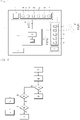
- the invention is here implemented in audio reproduction equipment which is in this case a connected speaker 1.
- the connected speaker 1 includes an audio reproduction unit 2, an audio capture unit 3, a processing module 4 and a communication module 5.
- the audio reproduction unit 2 comprises a set of loudspeakers 6 comprising at least one, in this case a plurality of loudspeakers 7 integrated into an acoustic enclosure, as well as electronic components 8 arranged to process and transmit signals audio emitted to the loudspeakers 7 which restore them by generating sound signals.
- the electronic components 8 notably comprise amplifiers.
- the electronic components 8 form several audio channels each connected to one or more loudspeakers 7.
- the audio capture unit 3 comprises a set of microphones 9 comprising at least one, in this case a plurality of microphones 10 as well as electronic components 11 arranged to acquire and process received audio signals produced by the microphones 10 when these this capture sound signals.
- the electronic components 11 notably comprise one or more analog-digital converters which transform the analog audio signals produced by the microphones 10 into digital signals.
- the processing module 4 comprises a processing component 12 which is suitable for executing program instructions to implement the self-diagnosis method according to the invention.
- the program is stored in a memory module 13 comprising one or more memories of different type (volatile, non-volatile) and connected or integrated in the processing component 12.
- the processing component 12 is for example a processor, a microcontroller, a DSP (for Digital Signal Processor, which can be translated as “digital signal processor”), or a programmable logic circuit such as an FPGA (for Field Programmable Gate Arrays ) or an ASIC (for Application Specific Integrated Circuit ) .
- the communication module 5 implements a wireless connection here using a Wi-Fi protocol.
- the communication module 5 makes it possible to connect the connected enclosure 1 to a residential gateway located in the dwelling of the user of the enclosure. connected 1.
- the connected speaker 1 can thus be connected to a communication network (for example the Internet) via its communication module 5 and the residential gateway.
- the link could be another wireless link (for example a Bluetooth link), or else a wired link.
- the self-diagnosis method according to the invention consists in acquiring or producing emitted test audio signals Se and broadcasting them via the loudspeaker(s) 7 which generate then test beeps So.
- the processing component 12 acquires received test audio signals Sr produced by the microphone(s) 10 and resulting from reception by the microphone(s) 10 of the test sound signals.
- the processing component 12 analyzes the received test audio signals Sr to establish a first diagnosis of the audio reproduction unit 2 and a second diagnosis of the audio capture unit 3.
- the processing component 12 thus establishes first of all, within the framework of the first diagnosis of the audio reproduction unit 2, a diagnosis relating to a first group of loudspeakers tested and to the loudspeaker.
- the first group of loudspeakers tested comprises at least a first loudspeaker 7a of the set of loudspeakers 6.
- the first group of loudspeakers tested which is targeted by this diagnosis can comprise a single loudspeaker, all the loudspeakers, or only certain loudspeakers of loudspeaker set 6.
- Performing the diagnosis uses at least a first microphone 10a of the set of microphones 9. Again, it is possible to use a single microphone, all the microphones, or even only certain microphones of the set of microphones 9.
- the audio test signals emitted Se comprise a first emitted signal Sel which is broadcast via the first loudspeaker(s) 7a of the first group of loudspeakers tested.
- the first signal emitted Sel is a pre-recorded signal.
- the received test audio signals Sr comprise, for each first microphone 10a, a first received signal Sr1 produced by said first microphone 10a.
- the processing component 12 produces and broadcasts the first transmitted signal Sel via the first group of loudspeakers tested (step E1).
- the first transmitted signal Sel is broadcast successively by each of the first loudspeakers 7a which each produce a first sound signal So1.
- the first transmitted signal Sel here comprises a first sinusoidal signal having a frequency lower than 100Hz, here equal to 50Hz.
- the first sinusoidal signal is a pure sine.
- the first microphones 10a capture the first sound signal So1 produced by said first loudspeaker 7a (step E2).
- the processing component 12 acquires the first received signal Sr1 produced by each first microphone 10a.
- the processing component 12 verifies whether or not the first received signal Sr1 is consistent with the first transmitted signal Sel (step E3).
- step E4 the processing component 12 launches an acoustic recalibration phase, which will be mentioned below.
- the processing component 12 verifies that the first transmitted signal Sel is indeed present in the first received signal Sr1 (step E5).
- step E6 If the first transmitted signal Sel is not present in the first received signal Sr1, an irremediable failure of the first loudspeaker 7a is detected (step E6).
- step E5 if the first transmitted signal Sel is indeed present in the first received signal Sr1, the processing component 12 analyzes the first received signal Sr1 to detect a residual noise signal also present in the first received signal Sr1.
- the analysis is a spectral analysis which uses a spectral measurement of the first received signal Sr1.
- the spectral measurement shows a peak at the frequency of the fundamental, as well as possibly other peaks at the frequencies of the harmonics (multiples of the fundamental).
- the processing component 12 By removing these peaks from the spectrum, the processing component 12 obtains the spectrum of the residual noise signal, which is normally weak and at the very least clearly lower than the preceding peaks.
- the residual noise signal will be high: this is the noise of the airflow turbulence of the leaks.
- the processing component 12 checks whether the residual noise signal has a frequency greater than a predefined frequency and a level greater than a predefined level, the predefined frequency being greater than a first frequency of the first transmitted signal Sel (step E7). If this is the case, the processing component 12 detects a leak in the acoustic enclosure (step E8).
- step E7 if the sealing defect is not detected, the processing component 12 launches an acoustic recalibration phase (step E9).
- each first loudspeaker 7a emits the first transmitted signal Sel successively.
- the first transmitted signal Sel it is possible to cause the first transmitted signal Sel to be transmitted by several first loudspeakers 7a simultaneously. In this case, if a fault is detected, it is possible either to incriminate all the first loudspeakers 7a concerned, or to have the first signal emitted Sel retransmitted by the first loudspeakers 7a successively to precisely identify the first loudspeaker or loudspeakers 7a at the origin of the fault.
- a pure sine at a medium frequency (for example equal to 500 Hz) can only be used to verify the presence of a loudspeaker.
- a pure sine at a low frequency (for example equal to 50 Hz) can be used to verify the presence of a loudspeaker and to ensure that its acoustic enclosure is sealed.
- Pink noise can be used to verify the presence of a speaker and its frequency response.
- a frequency sweep can be used to check the presence of a loudspeaker, its frequency response, its THD (for Total Harmonie Distortion or Rates of Harmonic Distortion in French), and possible parasitic vibrations in the connected speaker 1.
- the implementation of the first diagnosis of the audio reproduction unit 2 can therefore consist in detecting other faults.
- the self-diagnosis method can establish a diagnosis of a second group of loudspeakers tested comprising at least one second loudspeaker 7b of the set of loudspeakers 6.
- the second group of loudspeakers tested which is targeted by this diagnostic may include a single loudspeaker, all the loudspeakers, or only certain loudspeakers of the set of loudspeakers 6.
- the second loudspeakers 7b can be the same as the first loudspeaker(s) 7a.
- Carrying out the diagnosis uses at least a second microphone 10b of the set of microphones 9. Again, it is possible to use a single microphone, all the microphones, or else only certain microphones of the set of microphones 9.
- the or the second microphones 10b can be the same as the first microphone(s) 10a.
- the transmitted test audio signals comprise a second transmitted signal Se2 which is broadcast via the second loudspeaker(s) 7b of the second group of loudspeakers tested.
- the test audio signals received include, for each second microphone 10b, a second received signal Sr2 produced by said second microphone 10b.
- the second emitted signal Se2 is emitted successively by each second loudspeaker 7b.
- the second transmitted signal Se2 here comprises a succession of second sinusoidal signals exhibiting distinct second frequencies and forming a frequency sweep.
- the second sinusoidal signals are pure sines.
- the frequencies emitted are for example between 31.25 Hz and 1 kHz, per third octave, that is to say: 31.25 Hz x 2 ⁇ (N ⁇ 1/3).
- the frequencies could of course be different, and for example between 20 Hz and 2 kHz, in steps of a multiplicative factor equal to 1.58: 20 Hz, 31.7 Hz, 50.2 Hz, ..., 1.26 kHz, 2 kHz.
- Each frequency is for example transmitted for 500 ms.
- the second microphones 10b capture the second sound signal So2 produced by said second loudspeaker 7b.
- the processing component 12 acquires the second received signal Sr2 produced by each second microphone 10b.
- the processing component 12 implements a spectral analysis which, for each second sinusoidal signal of the second signal emitted Se2, that is to say for each frequency emitted, consists in carrying out measurements of a level of a fundamental and of harmonic levels of the second received audio signal Sr2, and detecting a fault from said measurements.
- the processing component 12 calculates a ratio between a sum of the levels of the harmonics and the level of the fundamental, and detects a fault from said ratio.
- the level of the fundamental gives the frequency response of the audio reproduction unit 2.
- the harmonics are the multiples of the fundamental.
- the distortion can be calculated by taking into account the first five harmonics of the second received signal Sr2.
- the fault detected is an internal fault in the second loudspeaker 7b.
- the fault detected is for example a deterioration of the membrane or of the suspension, a fault in the alignment of the coil, etc.
- the processing component 12 can detect a vibration fault by calculating the ratio between a sum of the levels of the harmonics and the level of the fundamental, the harmonics taken into account being the harmonics of orders greater than ten of the second received signal Sr2.
- the fault detected is a vibration fault manifested by the presence in the connected enclosure 1 of first vibration levels that are too high at first vibration frequencies.
- Each first vibration frequency is therefore an emitted frequency, which is associated with a first vibration level (ratio between the sum of the levels of the harmonics and the level of the fundamental, that is to say of said first vibration frequency) too high and symptomatic of a vibration defect.
- the processing component therefore establishes a first list of frequencies for which the level of vibration is greater than a predefined threshold, which is for example equal to 5%.
- the processing component 12 uses the set of loudspeakers 6 to communicate with the user and ask him to move the connected speaker 1.
- the processing component 12 again broadcasts the second transmitted signal Se2 via the second loudspeaker 7b and again analyzes the second received signal Sr2 to evaluate second vibration levels at second vibration frequencies.
- the second vibration frequencies are again the emitted frequencies of the signal Se2.
- the processing component attempts to detect excessively high second vibration levels associated with second vibration frequencies.
- the processing component therefore establishes a second list of frequencies for which the level of vibration is greater than the predefined threshold.
- the processing component 12 then compares the first vibration levels with the second vibration levels, and/or the first vibration frequencies with the second vibration frequencies, in order to determine whether the fault detected comes from the positioning of the connected speaker 1 or from an internal fault in the connected speaker 1.
- the processing component considers that there is a vibration defect at these frequencies, which is intrinsic to the connected speaker 1.
- the acoustic recalibration phase can be implemented at any time, and for example periodically, to ensure that the audio reproduction performance of the loudspeaker 1 is optimal.
- the acoustic recalibration phase can also be implemented, as we have seen, following the completion of the first diagnosis, i.e. at steps E4 and E9: see picture 2 .
- the acoustic recalibration phase can also be implemented when the existence of an acoustic defect is observed by comparing the latest results with those previously stored.
- the acoustic defect in question may consist of an incoherent frequency response, due for example to vibrations, and requiring recalibration in order to approximate the initial acoustic characteristics.
- the acoustic recalibration may relate to a third group of loudspeakers tested comprising at least a third loudspeaker 7c of the set of loudspeakers 6.
- the third group of loudspeakers tested which is concerned by this recalibration can comprise a single speaker, all speakers, or only some speakers in the speaker set.
- the third loudspeaker(s) 7c can be the same as the first loudspeaker(s) 7a or the second loudspeaker(s) 7b.
- At least one third microphone 10c from the set of microphones 9 is again used. It is possible to use a single microphone, all the microphones, or else only certain microphones from the set of microphones 9.
- the third microphone(s) 10c can be the same as the first microphone(s) 10a or the second microphone(s) 10b.
- the emitted test audio signals Se include a third emitted signal Se3 which is broadcast via the third loudspeaker(s) 7c of the third group of loudspeakers tested.
- the test audio signals received include, for each third microphone 10c, a third received signal Sr3 produced by said third microphone 10c.
- a third sound signal So3 produced by at least a third loudspeaker 7c
- the third microphone 10c produces a third current received signal Sr3.
- the third current signal received is recorded in a non-volatile memory of the memory module 13 (step E10).
- the processing component 12 checks whether the memory contains at least a third previous received signal which was previously transmitted by the same third loudspeaker 7c (or the same third loudspeakers 7c) and recorded by the processing component 12 (step E11).
- step E12 the acoustic recalibration phase is not carried out
- the processing component 12 analyzes the current third received signal by comparing it with the previous third received signals stored in the memory (step E13).
- the processing component 12 attempts to detect an acoustic defect from the results of said comparison (step E14).
- step E15 If no acoustic fault is detected, the decision process ends; the acoustic recalibration phase is not carried out (step E15).
- the processing component 12 performs a recalibration of the connected speaker 1 to correct said acoustic defect (step E16).
- the processing component 12 can decide to limit the level of the audio signals emitted in this frequency band, if said frequency band is sufficiently narrow.
- the processing component 12 decides to limit the level of the audio signals transmitted if the width of the frequency band is less than a predetermined threshold.
- the predetermined threshold is for example equal to 1/6 of an octave.
- the acoustic recalibration can also comprise a modification of the audio equalization of an audio channel integrating the third loudspeaker 7c concerned, so as to obtain the desired shape of the spectrum (for example a flat frequency response).
- the transmitted test audio signals comprise a fourth transmitted signal Se4.
- the fourth transmitted signal Se4 is broadcast via a fourth group of loudspeakers comprising at least a fourth loudspeaker 7d of the set of loudspeakers 6, which thus emits a fourth sound signal So4.
- the processing component 12 begins by adjusting the sound volume of the connected speaker 1 to a predefined level (for example 50% or 100% of the maximum volume): step E20. This step is optional.
- the processing component 12 uses the set of loudspeakers 6 to ask the user to check that no object is obstructing the inputs of the microphones 10 of the set of microphones 9 nor the outputs of the loudspeakers 7 of the set of loudspeakers 6 (step E21). This step is optional.
- the processing component 12 initializes the audio capture on the microphones 10d which are the tested microphones (step E22).
- the processing component 12 broadcasts the fourth transmitted signal Se4 via the fourth group of loudspeakers (step E23), which produces a fourth sound signal So4.
- the processing component 12 then checks that the fourth sound signal So4 has indeed been received by at least one tested microphone (step E24).
- the processing component 12 verifies that the fourth sound signal So4 has indeed been received by all the microphones tested (step E25).
- processing component 12 optionally implements the first diagnosis (if this has not already been carried out): step E26.
- step E25 if at least one first microphone tested has indeed received the fourth sound signal So4 and if at least one second microphone tested has not received said fourth sound signal So4, the processing component 12 detects an irremediable failure of the second microphone(s) tested (step E27).
- step E24 if none of the microphones tested has received the fourth sound signal So4, the processing component 12 asks the user if he has heard the fourth sound signal So4 (step E28).
- the processing component 12 detects an irremediable failure of a first subsystem belonging to the audio reproduction unit 2 and comprising the fourth group of loudspeakers (step E29).
- the processing component 12 detects an irremediable failure of a second subsystem belonging to the audio capture unit 3 and comprising the microphones tested (step E30) .
- step E23 or step E24 if one or more microphones tested have not received the fourth sound signal So4, the processing component 12 can use the set of loudspeakers 6 to request the user to check that no object obstructs the inputs of the microphones 10 of the set of microphones 9 nor the outputs of the loudspeakers 7 of the set of loudspeakers 6 (if this verification has not already been carried out). If this is the case, the second diagnosis is restarted.
- step E24 if none of the microphones tested has received the fourth sound signal So4, the processing component, before asking the user if he has heard the fourth sound signal So4, emits again the fourth sound signal So4 using a fifth loudspeaker different from the fourth loudspeaker.
- the processing component detects an irremediable failure of the fourth loudspeaker if the sound signal So4 is this time well received by at least one of the microphones tested.
- the invention therefore makes it possible to implement a mutual self-diagnosis by using the set of microphones 9 to establish the first diagnosis of the audio reproduction unit 2, and by using the set of loudspeakers 6 to establish the second audio capture unit diagnostics 3.
- the first diagnosis and the second diagnosis can be implemented periodically, each time testing all 7 loudspeakers or only certain loudspeakers 7, and each time testing all 10 microphones or only some 10 microphones.
- the regular implementation of the self-diagnosis process makes it possible to solve the problem of the modification of the environment of the connected speaker 1: displacement of the connected speaker 1, object placed nearby, etc.
- the microphones 10 it is noted that it is possible, during the implementation of the first diagnosis (relating to the loudspeakers 7), to test the first microphones 10a. For example, following step E2 visible on the picture 2 , it is possible to compare the first received signals Sr1 produced by the first microphones 10a with each other. If the first received signal Sr1 produced by one of the first microphones 10a is inconsistent with the other first received signals Sr1 produced by the other first microphones 10a, the processing component 12 detects a failure of the first microphone 10a in question.
- the connected speaker 1 can transmit to the manufacturer, via the communication module 5, the results of the tests carried out. This information can be uploaded to a database to allow statistical processing of the data.
- the invention minimizes interactions with the user.
- the connected speaker 1 can perfectly inform the user of the presence and the nature of this defect, and can guide him to possibly try to correct this defect.
- the manufacturer can also possibly contact the user to help him solve certain problems reported by the connected speaker 1.
- the invention therefore makes it possible to detect the irremediable failure of one or more loudspeakers 7, the irremediable failure of one or more audio channels (amplifier, etc.), the irremediable failure of one or more microphones 10.
- invention also makes it possible to inform the user and/or to proactively inform the After-Sales Service, and to update the product statistical data.
- the invention also makes it possible to detect an under-optimized use of the audio reproduction unit 2 (modification of the user environment, natural aging of the audio elements, etc.).
- the invention can also propose to the user to carry out an acoustic recalibration in order to take full advantage over time of the characteristics and performance of his connected speaker 1.
- the audio reproduction equipment in which the invention is implemented is of course not necessarily a connected speaker, but can be any electronic equipment incorporating one or more loudspeakers and one or more microphones: residential gateway, decoder box , voice assistant, tablet, smartphone, etc.
- the transmitted test audio signals can be pre-recorded, generated by the processing component 12, or else obtained from the network via the communication module 5.
Landscapes
- Physics & Mathematics (AREA)
- Engineering & Computer Science (AREA)
- Acoustics & Sound (AREA)
- Signal Processing (AREA)
- Health & Medical Sciences (AREA)
- General Health & Medical Sciences (AREA)
- Otolaryngology (AREA)
- Circuit For Audible Band Transducer (AREA)
Applications Claiming Priority (1)
| Application Number | Priority Date | Filing Date | Title |
|---|---|---|---|
| FR2103681A FR3121810A1 (fr) | 2021-04-09 | 2021-04-09 | Procédé d’auto-diagnostic d’un équipement de restitution audio |
Publications (2)
| Publication Number | Publication Date |
|---|---|
| EP4072162A1 true EP4072162A1 (de) | 2022-10-12 |
| EP4072162B1 EP4072162B1 (de) | 2024-08-28 |
Family
ID=75850382
Family Applications (1)
| Application Number | Title | Priority Date | Filing Date |
|---|---|---|---|
| EP22167041.7A Active EP4072162B1 (de) | 2021-04-09 | 2022-04-06 | Selbstdiagnoseverfahren eines audiowiedergabegeräts |
Country Status (3)
| Country | Link |
|---|---|
| US (1) | US12156002B2 (de) |
| EP (1) | EP4072162B1 (de) |
| FR (1) | FR3121810A1 (de) |
Citations (5)
| Publication number | Priority date | Publication date | Assignee | Title |
|---|---|---|---|---|
| JP2007124203A (ja) * | 2005-10-27 | 2007-05-17 | Yamaha Corp | マルチスピーカシステムおよびマルチマイクシステム |
| US20170289717A1 (en) * | 2016-03-31 | 2017-10-05 | Sonos, Inc. | Defect Detection via Audio Playback |
| US20180213340A1 (en) * | 2017-01-26 | 2018-07-26 | W. L. Gore & Associates, Inc. | High throughput acoustic vent structure test apparatus |
| CN108430026A (zh) * | 2018-03-07 | 2018-08-21 | 广州艾美网络科技有限公司 | 音频设备故障检测方法和点唱设备 |
| CN109379689A (zh) * | 2018-10-30 | 2019-02-22 | Oppo广东移动通信有限公司 | 扬声器总谐波失真测量方法、装置、存储介质及测量系统 |
Family Cites Families (2)
| Publication number | Priority date | Publication date | Assignee | Title |
|---|---|---|---|---|
| US8600067B2 (en) * | 2008-09-19 | 2013-12-03 | Personics Holdings Inc. | Acoustic sealing analysis system |
| WO2013126603A1 (en) * | 2012-02-21 | 2013-08-29 | Intertrust Technologies Corporation | Audio reproduction systems and methods |
-
2021
- 2021-04-09 FR FR2103681A patent/FR3121810A1/fr not_active Withdrawn
-
2022
- 2022-04-06 EP EP22167041.7A patent/EP4072162B1/de active Active
- 2022-04-07 US US17/715,499 patent/US12156002B2/en active Active
Patent Citations (5)
| Publication number | Priority date | Publication date | Assignee | Title |
|---|---|---|---|---|
| JP2007124203A (ja) * | 2005-10-27 | 2007-05-17 | Yamaha Corp | マルチスピーカシステムおよびマルチマイクシステム |
| US20170289717A1 (en) * | 2016-03-31 | 2017-10-05 | Sonos, Inc. | Defect Detection via Audio Playback |
| US20180213340A1 (en) * | 2017-01-26 | 2018-07-26 | W. L. Gore & Associates, Inc. | High throughput acoustic vent structure test apparatus |
| CN108430026A (zh) * | 2018-03-07 | 2018-08-21 | 广州艾美网络科技有限公司 | 音频设备故障检测方法和点唱设备 |
| CN109379689A (zh) * | 2018-10-30 | 2019-02-22 | Oppo广东移动通信有限公司 | 扬声器总谐波失真测量方法、装置、存储介质及测量系统 |
Non-Patent Citations (2)
| Title |
|---|
| "Sound system equipment - Part 21: Acoustical (output-based) measurements", IEC 60268-21:2018, IEC, 3, RUE DE VAREMBÉ, PO BOX 131, CH-1211 GENEVA 20, SWITZERLAND, 7 November 2018 (2018-11-07), pages 1 - 77, XP082013922 * |
| KLIPPEL ET AL: "Evaluation of Audio Performance over Product Life", AES CONVENTION 142; MAY 2017, AES, 60 EAST 42ND STREET, ROOM 2520 NEW YORK 10165-2520, USA, 11 May 2017 (2017-05-11), XP040687405 * |
Also Published As
| Publication number | Publication date |
|---|---|
| FR3121810A1 (fr) | 2022-10-14 |
| EP4072162B1 (de) | 2024-08-28 |
| US20220329956A1 (en) | 2022-10-13 |
| US12156002B2 (en) | 2024-11-26 |
Similar Documents
| Publication | Publication Date | Title |
|---|---|---|
| US11626850B2 (en) | Automated tuning by measuring and equalizing speaker output in an audio environment | |
| US9596553B2 (en) | Apparatus and method for performing an audio measurement sweep | |
| US12192737B2 (en) | Automated audio tuning and compensation procedure | |
| EP2136359B1 (de) | Verfahren und Gerät zur Messung der Verständlichkeit einer Vorrichtung zur Schallausstrahlung | |
| CN103179495A (zh) | 移动终端的耳机麦克风和听筒的音频测试方法及系统 | |
| CN103179240A (zh) | 移动终端的音频测试方法及测试系统 | |
| US12267655B2 (en) | Automated audio tuning launch procedure and report | |
| EP2042000A2 (de) | Verfahren und vorrichtung zur diagnostizierung des betriebszustandes einer tonanlage | |
| WO2023081534A1 (en) | Automated audio tuning launch procedure and report | |
| CN114584908B (zh) | 助听器的声学测试方法、装置以及设备 | |
| CN109195089A (zh) | 用于产品内扬声器电声参数的测试方法及系统 | |
| EP4072162B1 (de) | Selbstdiagnoseverfahren eines audiowiedergabegeräts | |
| CN111274073A (zh) | 一种服务器声卡音频功能诊断方法及系统 | |
| CN121284449A (zh) | 音频信号的输出方法、装置、电子设备和存储介质 | |
| CN115460527A (zh) | 基于心理声学的耳机失真测量方法、存储介质、耳机 | |
| CN112951265A (zh) | 音频处理方法、装置、电子设备和存储介质 | |
| CN117851975A (zh) | 噪声模型确定方法、装置、存储介质及计算机设备 | |
| CN113473348A (zh) | 扫频音源定位方法、音频设备品质测试方法、系统及设备 | |
| JP2022181759A (ja) | 音声品質評価装置、音声品質評価方法、および音声品質評価プログラム | |
| CN117558302B (zh) | 音频测试方法、装置、电子设备及存储介质 | |
| FR3112017A1 (fr) | Equipement électronique comprenant un simulateur de distorsion | |
| CN115668984A (zh) | 音频扬声器的瞬态多音调测试信号和方法 | |
| CN105763892B (zh) | 一种检测媒体节目播出服务质量的方法及装置 | |
| EP3844979A1 (de) | Verfahren und vorrichtung zur steuerung der verzerrung eines lautsprechersystems an bord eines fahrzeuges | |
| FR2984581A1 (fr) | Methode pour mesurer une distorsion causee par un appareil audionumerique |
Legal Events
| Date | Code | Title | Description |
|---|---|---|---|
| PUAI | Public reference made under article 153(3) epc to a published international application that has entered the european phase |
Free format text: ORIGINAL CODE: 0009012 |
|
| STAA | Information on the status of an ep patent application or granted ep patent |
Free format text: STATUS: EXAMINATION IS IN PROGRESS |
|
| 17P | Request for examination filed |
Effective date: 20220406 |
|
| AK | Designated contracting states |
Kind code of ref document: A1 Designated state(s): AL AT BE BG CH CY CZ DE DK EE ES FI FR GB GR HR HU IE IS IT LI LT LU LV MC MK MT NL NO PL PT RO RS SE SI SK SM TR |
|
| RBV | Designated contracting states (corrected) |
Designated state(s): AL AT BE BG CH CY CZ DE DK EE ES FI FR GB GR HR HU IE IS IT LI LT LU LV MC MK MT NL NO PL PT RO RS SE SI SK SM TR |
|
| RAP3 | Party data changed (applicant data changed or rights of an application transferred) |
Owner name: SAGEMCOM BROADBAND SAS |
|
| GRAP | Despatch of communication of intention to grant a patent |
Free format text: ORIGINAL CODE: EPIDOSNIGR1 |
|
| STAA | Information on the status of an ep patent application or granted ep patent |
Free format text: STATUS: GRANT OF PATENT IS INTENDED |
|
| INTG | Intention to grant announced |
Effective date: 20240320 |
|
| GRAS | Grant fee paid |
Free format text: ORIGINAL CODE: EPIDOSNIGR3 |
|
| GRAA | (expected) grant |
Free format text: ORIGINAL CODE: 0009210 |
|
| STAA | Information on the status of an ep patent application or granted ep patent |
Free format text: STATUS: THE PATENT HAS BEEN GRANTED |
|
| AK | Designated contracting states |
Kind code of ref document: B1 Designated state(s): AL AT BE BG CH CY CZ DE DK EE ES FI FR GB GR HR HU IE IS IT LI LT LU LV MC MK MT NL NO PL PT RO RS SE SI SK SM TR |
|
| REG | Reference to a national code |
Ref country code: CH Ref legal event code: EP |
|
| REG | Reference to a national code |
Ref country code: DE Ref legal event code: R096 Ref document number: 602022005584 Country of ref document: DE |
|
| REG | Reference to a national code |
Ref country code: IE Ref legal event code: FG4D Free format text: LANGUAGE OF EP DOCUMENT: FRENCH |
|
| REG | Reference to a national code |
Ref country code: LT Ref legal event code: MG9D |
|
| PG25 | Lapsed in a contracting state [announced via postgrant information from national office to epo] |
Ref country code: NO Free format text: LAPSE BECAUSE OF FAILURE TO SUBMIT A TRANSLATION OF THE DESCRIPTION OR TO PAY THE FEE WITHIN THE PRESCRIBED TIME-LIMIT Effective date: 20241128 |
|
| REG | Reference to a national code |
Ref country code: AT Ref legal event code: MK05 Ref document number: 1719231 Country of ref document: AT Kind code of ref document: T Effective date: 20240828 |
|
| PG25 | Lapsed in a contracting state [announced via postgrant information from national office to epo] |
Ref country code: FI Free format text: LAPSE BECAUSE OF FAILURE TO SUBMIT A TRANSLATION OF THE DESCRIPTION OR TO PAY THE FEE WITHIN THE PRESCRIBED TIME-LIMIT Effective date: 20240828 Ref country code: NL Free format text: LAPSE BECAUSE OF FAILURE TO SUBMIT A TRANSLATION OF THE DESCRIPTION OR TO PAY THE FEE WITHIN THE PRESCRIBED TIME-LIMIT Effective date: 20240828 Ref country code: PT Free format text: LAPSE BECAUSE OF FAILURE TO SUBMIT A TRANSLATION OF THE DESCRIPTION OR TO PAY THE FEE WITHIN THE PRESCRIBED TIME-LIMIT Effective date: 20241230 Ref country code: PL Free format text: LAPSE BECAUSE OF FAILURE TO SUBMIT A TRANSLATION OF THE DESCRIPTION OR TO PAY THE FEE WITHIN THE PRESCRIBED TIME-LIMIT Effective date: 20240828 Ref country code: GR Free format text: LAPSE BECAUSE OF FAILURE TO SUBMIT A TRANSLATION OF THE DESCRIPTION OR TO PAY THE FEE WITHIN THE PRESCRIBED TIME-LIMIT Effective date: 20241129 |
|
| PG25 | Lapsed in a contracting state [announced via postgrant information from national office to epo] |
Ref country code: BG Free format text: LAPSE BECAUSE OF FAILURE TO SUBMIT A TRANSLATION OF THE DESCRIPTION OR TO PAY THE FEE WITHIN THE PRESCRIBED TIME-LIMIT Effective date: 20240828 |
|
| PG25 | Lapsed in a contracting state [announced via postgrant information from national office to epo] |
Ref country code: LV Free format text: LAPSE BECAUSE OF FAILURE TO SUBMIT A TRANSLATION OF THE DESCRIPTION OR TO PAY THE FEE WITHIN THE PRESCRIBED TIME-LIMIT Effective date: 20240828 |
|
| REG | Reference to a national code |
Ref country code: NL Ref legal event code: MP Effective date: 20240828 |
|
| PG25 | Lapsed in a contracting state [announced via postgrant information from national office to epo] |
Ref country code: IS Free format text: LAPSE BECAUSE OF FAILURE TO SUBMIT A TRANSLATION OF THE DESCRIPTION OR TO PAY THE FEE WITHIN THE PRESCRIBED TIME-LIMIT Effective date: 20241228 Ref country code: AT Free format text: LAPSE BECAUSE OF FAILURE TO SUBMIT A TRANSLATION OF THE DESCRIPTION OR TO PAY THE FEE WITHIN THE PRESCRIBED TIME-LIMIT Effective date: 20240828 |
|
| PG25 | Lapsed in a contracting state [announced via postgrant information from national office to epo] |
Ref country code: HR Free format text: LAPSE BECAUSE OF FAILURE TO SUBMIT A TRANSLATION OF THE DESCRIPTION OR TO PAY THE FEE WITHIN THE PRESCRIBED TIME-LIMIT Effective date: 20240828 |
|
| PG25 | Lapsed in a contracting state [announced via postgrant information from national office to epo] |
Ref country code: RS Free format text: LAPSE BECAUSE OF FAILURE TO SUBMIT A TRANSLATION OF THE DESCRIPTION OR TO PAY THE FEE WITHIN THE PRESCRIBED TIME-LIMIT Effective date: 20241128 Ref country code: ES Free format text: LAPSE BECAUSE OF FAILURE TO SUBMIT A TRANSLATION OF THE DESCRIPTION OR TO PAY THE FEE WITHIN THE PRESCRIBED TIME-LIMIT Effective date: 20240828 |
|
| PG25 | Lapsed in a contracting state [announced via postgrant information from national office to epo] |
Ref country code: RS Free format text: LAPSE BECAUSE OF FAILURE TO SUBMIT A TRANSLATION OF THE DESCRIPTION OR TO PAY THE FEE WITHIN THE PRESCRIBED TIME-LIMIT Effective date: 20241128 Ref country code: PT Free format text: LAPSE BECAUSE OF FAILURE TO SUBMIT A TRANSLATION OF THE DESCRIPTION OR TO PAY THE FEE WITHIN THE PRESCRIBED TIME-LIMIT Effective date: 20241230 Ref country code: PL Free format text: LAPSE BECAUSE OF FAILURE TO SUBMIT A TRANSLATION OF THE DESCRIPTION OR TO PAY THE FEE WITHIN THE PRESCRIBED TIME-LIMIT Effective date: 20240828 Ref country code: NO Free format text: LAPSE BECAUSE OF FAILURE TO SUBMIT A TRANSLATION OF THE DESCRIPTION OR TO PAY THE FEE WITHIN THE PRESCRIBED TIME-LIMIT Effective date: 20241128 Ref country code: NL Free format text: LAPSE BECAUSE OF FAILURE TO SUBMIT A TRANSLATION OF THE DESCRIPTION OR TO PAY THE FEE WITHIN THE PRESCRIBED TIME-LIMIT Effective date: 20240828 Ref country code: LV Free format text: LAPSE BECAUSE OF FAILURE TO SUBMIT A TRANSLATION OF THE DESCRIPTION OR TO PAY THE FEE WITHIN THE PRESCRIBED TIME-LIMIT Effective date: 20240828 Ref country code: IS Free format text: LAPSE BECAUSE OF FAILURE TO SUBMIT A TRANSLATION OF THE DESCRIPTION OR TO PAY THE FEE WITHIN THE PRESCRIBED TIME-LIMIT Effective date: 20241228 Ref country code: HR Free format text: LAPSE BECAUSE OF FAILURE TO SUBMIT A TRANSLATION OF THE DESCRIPTION OR TO PAY THE FEE WITHIN THE PRESCRIBED TIME-LIMIT Effective date: 20240828 Ref country code: GR Free format text: LAPSE BECAUSE OF FAILURE TO SUBMIT A TRANSLATION OF THE DESCRIPTION OR TO PAY THE FEE WITHIN THE PRESCRIBED TIME-LIMIT Effective date: 20241129 Ref country code: FI Free format text: LAPSE BECAUSE OF FAILURE TO SUBMIT A TRANSLATION OF THE DESCRIPTION OR TO PAY THE FEE WITHIN THE PRESCRIBED TIME-LIMIT Effective date: 20240828 Ref country code: ES Free format text: LAPSE BECAUSE OF FAILURE TO SUBMIT A TRANSLATION OF THE DESCRIPTION OR TO PAY THE FEE WITHIN THE PRESCRIBED TIME-LIMIT Effective date: 20240828 Ref country code: BG Free format text: LAPSE BECAUSE OF FAILURE TO SUBMIT A TRANSLATION OF THE DESCRIPTION OR TO PAY THE FEE WITHIN THE PRESCRIBED TIME-LIMIT Effective date: 20240828 Ref country code: AT Free format text: LAPSE BECAUSE OF FAILURE TO SUBMIT A TRANSLATION OF THE DESCRIPTION OR TO PAY THE FEE WITHIN THE PRESCRIBED TIME-LIMIT Effective date: 20240828 |
|
| PG25 | Lapsed in a contracting state [announced via postgrant information from national office to epo] |
Ref country code: SM Free format text: LAPSE BECAUSE OF FAILURE TO SUBMIT A TRANSLATION OF THE DESCRIPTION OR TO PAY THE FEE WITHIN THE PRESCRIBED TIME-LIMIT Effective date: 20240828 Ref country code: RO Free format text: LAPSE BECAUSE OF FAILURE TO SUBMIT A TRANSLATION OF THE DESCRIPTION OR TO PAY THE FEE WITHIN THE PRESCRIBED TIME-LIMIT Effective date: 20240828 Ref country code: DK Free format text: LAPSE BECAUSE OF FAILURE TO SUBMIT A TRANSLATION OF THE DESCRIPTION OR TO PAY THE FEE WITHIN THE PRESCRIBED TIME-LIMIT Effective date: 20240828 |
|
| PG25 | Lapsed in a contracting state [announced via postgrant information from national office to epo] |
Ref country code: EE Free format text: LAPSE BECAUSE OF FAILURE TO SUBMIT A TRANSLATION OF THE DESCRIPTION OR TO PAY THE FEE WITHIN THE PRESCRIBED TIME-LIMIT Effective date: 20240828 |
|
| PG25 | Lapsed in a contracting state [announced via postgrant information from national office to epo] |
Ref country code: CZ Free format text: LAPSE BECAUSE OF FAILURE TO SUBMIT A TRANSLATION OF THE DESCRIPTION OR TO PAY THE FEE WITHIN THE PRESCRIBED TIME-LIMIT Effective date: 20240828 |
|
| PG25 | Lapsed in a contracting state [announced via postgrant information from national office to epo] |
Ref country code: IT Free format text: LAPSE BECAUSE OF FAILURE TO SUBMIT A TRANSLATION OF THE DESCRIPTION OR TO PAY THE FEE WITHIN THE PRESCRIBED TIME-LIMIT Effective date: 20240828 Ref country code: SK Free format text: LAPSE BECAUSE OF FAILURE TO SUBMIT A TRANSLATION OF THE DESCRIPTION OR TO PAY THE FEE WITHIN THE PRESCRIBED TIME-LIMIT Effective date: 20240828 |
|
| REG | Reference to a national code |
Ref country code: DE Ref legal event code: R097 Ref document number: 602022005584 Country of ref document: DE |
|
| PLBE | No opposition filed within time limit |
Free format text: ORIGINAL CODE: 0009261 |
|
| STAA | Information on the status of an ep patent application or granted ep patent |
Free format text: STATUS: NO OPPOSITION FILED WITHIN TIME LIMIT |
|
| PGFP | Annual fee paid to national office [announced via postgrant information from national office to epo] |
Ref country code: DE Payment date: 20250319 Year of fee payment: 4 |
|
| 26N | No opposition filed |
Effective date: 20250530 |
|
| PG25 | Lapsed in a contracting state [announced via postgrant information from national office to epo] |
Ref country code: SE Free format text: LAPSE BECAUSE OF FAILURE TO SUBMIT A TRANSLATION OF THE DESCRIPTION OR TO PAY THE FEE WITHIN THE PRESCRIBED TIME-LIMIT Effective date: 20240828 |
|
| REG | Reference to a national code |
Ref country code: CH Ref legal event code: H13 Free format text: ST27 STATUS EVENT CODE: U-0-0-H10-H13 (AS PROVIDED BY THE NATIONAL OFFICE) Effective date: 20251125 |
|
| PG25 | Lapsed in a contracting state [announced via postgrant information from national office to epo] |
Ref country code: LU Free format text: LAPSE BECAUSE OF NON-PAYMENT OF DUE FEES Effective date: 20250406 |
|
| PG25 | Lapsed in a contracting state [announced via postgrant information from national office to epo] |
Ref country code: MC Free format text: LAPSE BECAUSE OF FAILURE TO SUBMIT A TRANSLATION OF THE DESCRIPTION OR TO PAY THE FEE WITHIN THE PRESCRIBED TIME-LIMIT Effective date: 20240828 |
|
| REG | Reference to a national code |
Ref country code: BE Ref legal event code: MM Effective date: 20250430 |
|
| PG25 | Lapsed in a contracting state [announced via postgrant information from national office to epo] |
Ref country code: BE Free format text: LAPSE BECAUSE OF NON-PAYMENT OF DUE FEES Effective date: 20250430 |
|
| PG25 | Lapsed in a contracting state [announced via postgrant information from national office to epo] |
Ref country code: CH Free format text: LAPSE BECAUSE OF NON-PAYMENT OF DUE FEES Effective date: 20250430 |
|
| PG25 | Lapsed in a contracting state [announced via postgrant information from national office to epo] |
Ref country code: IE Free format text: LAPSE BECAUSE OF NON-PAYMENT OF DUE FEES Effective date: 20250406 |
|
| PGFP | Annual fee paid to national office [announced via postgrant information from national office to epo] |
Ref country code: FR Payment date: 20260319 Year of fee payment: 5 |