EP4072002B1 - Détermination sans capteur de la position du rotor d'un moteur synchrone à aimants permanents - Google Patents
Détermination sans capteur de la position du rotor d'un moteur synchrone à aimants permanents Download PDFInfo
- Publication number
- EP4072002B1 EP4072002B1 EP22164919.7A EP22164919A EP4072002B1 EP 4072002 B1 EP4072002 B1 EP 4072002B1 EP 22164919 A EP22164919 A EP 22164919A EP 4072002 B1 EP4072002 B1 EP 4072002B1
- Authority
- EP
- European Patent Office
- Prior art keywords
- determined
- magnet synchronous
- synchronous motor
- permanent magnet
- phase
- Prior art date
- Legal status (The legal status is an assumption and is not a legal conclusion. Google has not performed a legal analysis and makes no representation as to the accuracy of the status listed.)
- Active
Links
Images



Classifications
-
- H—ELECTRICITY
- H02—GENERATION; CONVERSION OR DISTRIBUTION OF ELECTRIC POWER
- H02P—CONTROL OR REGULATION OF ELECTRIC MOTORS, ELECTRIC GENERATORS OR DYNAMO-ELECTRIC CONVERTERS; CONTROLLING TRANSFORMERS, REACTORS OR CHOKE COILS
- H02P6/00—Arrangements for controlling synchronous motors or other dynamo-electric motors using electronic commutation dependent on the rotor position; Electronic commutators therefor
- H02P6/14—Electronic commutators
- H02P6/16—Circuit arrangements for detecting position
-
- H—ELECTRICITY
- H02—GENERATION; CONVERSION OR DISTRIBUTION OF ELECTRIC POWER
- H02P—CONTROL OR REGULATION OF ELECTRIC MOTORS, ELECTRIC GENERATORS OR DYNAMO-ELECTRIC CONVERTERS; CONTROLLING TRANSFORMERS, REACTORS OR CHOKE COILS
- H02P21/00—Arrangements or methods for the control of electric machines by vector control, e.g. by control of field orientation
- H02P21/24—Vector control not involving the use of rotor position or rotor speed sensors
-
- H—ELECTRICITY
- H02—GENERATION; CONVERSION OR DISTRIBUTION OF ELECTRIC POWER
- H02P—CONTROL OR REGULATION OF ELECTRIC MOTORS, ELECTRIC GENERATORS OR DYNAMO-ELECTRIC CONVERTERS; CONTROLLING TRANSFORMERS, REACTORS OR CHOKE COILS
- H02P21/00—Arrangements or methods for the control of electric machines by vector control, e.g. by control of field orientation
- H02P21/14—Estimation or adaptation of machine parameters, e.g. flux, current or voltage
- H02P21/18—Estimation of position or speed
-
- H—ELECTRICITY
- H02—GENERATION; CONVERSION OR DISTRIBUTION OF ELECTRIC POWER
- H02P—CONTROL OR REGULATION OF ELECTRIC MOTORS, ELECTRIC GENERATORS OR DYNAMO-ELECTRIC CONVERTERS; CONTROLLING TRANSFORMERS, REACTORS OR CHOKE COILS
- H02P6/00—Arrangements for controlling synchronous motors or other dynamo-electric motors using electronic commutation dependent on the rotor position; Electronic commutators therefor
- H02P6/14—Electronic commutators
- H02P6/16—Circuit arrangements for detecting position
- H02P6/18—Circuit arrangements for detecting position without separate position detecting elements
- H02P6/185—Circuit arrangements for detecting position without separate position detecting elements using inductance sensing, e.g. pulse excitation
-
- H—ELECTRICITY
- H02—GENERATION; CONVERSION OR DISTRIBUTION OF ELECTRIC POWER
- H02P—CONTROL OR REGULATION OF ELECTRIC MOTORS, ELECTRIC GENERATORS OR DYNAMO-ELECTRIC CONVERTERS; CONTROLLING TRANSFORMERS, REACTORS OR CHOKE COILS
- H02P2203/00—Indexing scheme relating to controlling arrangements characterised by the means for detecting the position of the rotor
- H02P2203/03—Determination of the rotor position, e.g. initial rotor position, during standstill or low speed operation
-
- H—ELECTRICITY
- H02—GENERATION; CONVERSION OR DISTRIBUTION OF ELECTRIC POWER
- H02P—CONTROL OR REGULATION OF ELECTRIC MOTORS, ELECTRIC GENERATORS OR DYNAMO-ELECTRIC CONVERTERS; CONTROLLING TRANSFORMERS, REACTORS OR CHOKE COILS
- H02P2207/00—Indexing scheme relating to controlling arrangements characterised by the type of motor
- H02P2207/05—Synchronous machines, e.g. with permanent magnets or DC excitation
Definitions
- the invention relates to a method for determining a rotor position of a three-phase permanent magnet synchronous motor, wherein the permanent magnet synchronous motor has a d-axis inductance (Ld) and a q-axis inductance (Lq) that differs from the d-axis inductance (Ld) relative to a d/q coordinate system having a d-axis and a q-axis as a rotor-fixed reference system, wherein each phase of the permanent magnet synchronous motor is assigned an inductance that changes depending on the rotor position, and wherein the rotor position is determined by means of the changing inductances.
- Ld d-axis inductance
- Lq q-axis inductance
- the invention relates to a method for the field-oriented control of a permanent magnet synchronous motor, in particular a permanent magnet synchronous motor used in a motor vehicle for an assistance system, wherein a rotor position of the permanent magnet synchronous motor necessary for the field-oriented control is determined by means of an above-mentioned method for determining a rotor position.
- the invention further relates to a control unit for the operation of a permanent magnet synchronous motor, as well as a steering system with such a control unit.
- a permanent magnet synchronous motor is essentially a combination of an induction motor and a brushless DC motor.
- a permanent magnet synchronous motor comprises a permanent magnet rotor and coils on the stator.
- the stator's coil design creates a sinusoidal waveform of the back electromotive force, also known as back EMF (EMF: electromotive force) or BEMF (BEMF: back electromotive force), making the permanent magnet synchronous motor more similar to an induction motor in this respect.
- EMF electromotive force
- BEMF back electromotive force
- Permanent magnet synchronous motors are frequently used in motor vehicles, particularly as servomotors. Such motors are particularly well-known in electromechanical power steering systems, but also in other vehicle assistance systems that include an electric motor. For example, such permanent magnet synchronous motors can also be used to drive an air conditioning compressor. Since the on-board power system of a motor vehicle provides a direct current, methods for controlling permanent magnet synchronous motors are usually based on PWM (Pulse Width Modulation). which makes it possible to simulate a multi-phase three-phase system electronically.
- PWM Pulse Width Modulation
- rotor position sensor units which can include Hall sensors and angle sensors.
- reliable control of the synchronous motor must be ensured in all cases. For this reason, a third rotor position sensor is often provided in such applications, increasing complexity and costs.
- a back EMF-based method also known as a BEMF-based method, is also known for determining the rotor position.
- a high-frequency signal is applied to the base voltage, and the induced current is determined, from which the rotor position is derived.
- a disadvantage of this method is that the high-frequency signal impairs the base voltage signal.
- Another disadvantage is the requirement to measure the current waveform induced by the applied signal.
- this method is essentially only applicable once a predetermined speed has been reached.
- the rotor position of a synchronous motor can be determined by determining the star-point voltage.
- This method exploits the fact that the star-point voltage depends on the inductance of the respective phase, which in turn depends on the rotor position.
- the PWM signal used is used as the excitation voltage. This requires that the inductances in the d- and q-axes are different in the d/q coordinate system.
- the motor's star point must be connected to the associated control unit. In order to determine the star-point voltage for different space vectors, a special DC bus-compatible pulse width modulation must also be used.
- RAVIKUMAR SETTY A ET AL "Comparison of high frequency signal injection techniques for rotor position estimation at low speed to standstill of PMSM", POWER ELECTRONICS (IICPE), 2012 IEEE 5TH INDIA INTERNATIONAL CONFERENCE ON, IEEE, December 6, 2012 , also provides an overview of various approaches for determining rotor position using high frequency signal injection (HFSI) techniques.
- HFSI high frequency signal injection
- a system for controlling an electric motor is also used in the WO 2020/161496 A1 discloses a motor having a rotor and stator windings.
- the system includes a sensor arrangement with a first sensor measuring the current in one phase of the motor and a second sensor measuring the rate of change of the current (dl/dt) in the phase of the motor.
- the system also includes a controller configured to drive the electric motor based on the feedback received from the sensor arrangement.
- the proposed solution provides a method for determining a rotor position of a three-phase permanent magnet synchronous motor, wherein the permanent magnet synchronous motor has a d-axis inductance (Ld) and a q-axis inductance (Lq) that differs from the d-axis inductance (Ld) relative to a d/q coordinate system having a d-axis and a q-axis as a rotor-fixed reference system.
- Each phase of the permanent magnet synchronous motor is assigned an inductance that changes depending on the rotor position, and the rotor position is determined using the changing inductances.
- a voltage is applied to the phases, the applied voltage causing a ripple current for each phase.
- the ripple current is determined for at least two of the three phases, and the inductance of the respective phase is determined based on the ripple current determined for the respective phase.
- the permanent magnet synchronous motor is a motor used in a motor vehicle, in particular a motor used in a safety-relevant system of a motor vehicle Motor, more particularly a motor used in a steering system of a motor vehicle.
- the permanent magnet synchronous motor is a motor with a salient pole rotor.
- the applied voltage is advantageously not affected by a further voltage superimposed on this voltage.
- the voltage is applied as a pulse-width modulated signal, also called a PWM signal.
- the permanent magnet synchronous motor is controlled by means of a PWM signal, wherein the PWM signal, in particular without superimposing another signal, is advantageously used to generate the ripple current.
- the PWM signal has a frequency of at least 10 kHz (kHz: kilohertz).
- the permanent magnet synchronous motor is controlled by means of space vector modulation using voltage space vectors, wherein the applied voltage space vector is advantageously used to generate the ripple current.
- the ripple current is advantageously determined as a current caused by a ripple voltage, with the ripple voltage advantageously resulting from the voltage difference between an instantaneous voltage and an average phase voltage.
- the instantaneous voltage is determined by the corresponding voltage space vector.
- the average phase voltage is determined, in particular, based on the phase duty cycles and/or an alpha-beta filter and/or the d-q voltage vectors.
- the phase voltage corresponding to the respective harmonic current is advantageously determined as the average phase voltage.
- the ripple current is thus advantageously caused for each phase by the excitation voltage, which results from the voltage difference between the applied voltage space vector and the average phase voltage.
- This excitation voltage is based on the pulse width modulation-based space vector modulation used to control the permanent magnet synchronous motor and therefore advantageously does not need to be additionally generated. This means that the generation of an additional voltage signal and the application of an additional voltage signal to an applied voltage are advantageously eliminated. Due to the high frequency at the converter output for the space vector modulation, in particular more than 10 kHz, in particular due to a frequency in a range from 12 kHz to 24 kHz, the excitation voltage is also advantageously high-frequency. In particular, a frequency of 16 kHz or 20 kHz is provided at the converter output.
- the voltage space vectors have, in particular, discrete voltage levels that interact with the phase voltage.
- the instantaneous voltages for the respective phases can be advantageously determined, taking into account the inductance Lu, Lv, Lw assigned to each winding phase U, V, W and thus to each phase, as shown in the following table, where Ubat denotes the voltage of the main voltage source, and when the method is used in a motor vehicle, in particular the voltage of the vehicle battery: Voltage space vector phase U (SV_ph_U) Voltage space vector phase V (SV_ph_V) Voltage space vector phase W (SV_ph_W) Up Ubat* (Lu/ (Lu + Lv x Lw)) SV_ph_U - Ubat SV_ph_U - Ubat Vp Ubat* (Lv/ (Lv + Lu x Lw)) SV_ph_V - Ubat SV_ph_V - Ubat Wp Ubat* (Lw/ (Lw + Lu x Lv)) SV_ph_W - Ubat SV_ph_W
- a gradient of the ripple current is determined for at least two of the three phases, wherein the inductance of the respective phase is determined from the gradient determined for a phase and the ripple voltage resulting for this phase.
- a gradient of the ripple current is determined for all three phases, wherein the inductance of the respective phase is determined from the gradient determined for a phase and the ripple voltage resulting for this phase.
- the determination of the gradient of the Ripple current for all three phases is particularly important when different voltage space vectors are applied. This allows the inductance for each phase to be determined for each gradient, taking the ripple voltage into account.
- An advantageous embodiment of the method provides that the gradient of the ripple current is determined for only two of the three phases, and the inductances of the two phases are determined from the gradient determined for one phase and the resulting ripple voltage for this phase.
- the inductances for the two phases are determined using the same voltage space vector.
- the inductance of the third phase is advantageously determined for this voltage space vector from the inductances determined for the other two phases.
- the gradient of the ripple current is determined by means of phase current measurement.
- a further advantageous embodiment provides that the gradient of the ripple current is determined by means of intermediate circuit current measurement.
- a microcontroller unit with an analog-to-digital converter is used to control the permanent magnet synchronous motor, wherein it is provided in particular that the inputs of the analog-to-digital converter of the microcontroller used to control the permanent magnet synchronous motor are used to measure the ripple current.
- at least two gradients of the ripple current of the phases can be determined by means of phase current measurement, and one gradient of the ripple current can be determined by means of intermediate circuit current measurement.
- the ripple current gradient is determined via an intermediate circuit current measurement or a low-side current measurement, it is provided in particular that a measurement is not carried out until a predetermined time after a switching operation, wherein the predetermined time is preferably dimensioned such that the signal at the operational amplifier output has stabilized. It is also advantageous to increase the duty cycle, i.e., the ratio of pulse duration to period duration, with respect to the voltage space vector in order to be able to determine the gradient of the ripple current sufficiently accurately. Since, during an intermediate circuit current measurement, for a specific applied voltage space vector, only the ripple current for one phase can initially be determined, at least two different additional voltage space vectors are advantageously used to determine the value for all three phases. The inductance for the respective phase is advantageously determined from the determined gradient of the ripple current and the associated voltage.
- a first rotor angle is determined from the determined inductance for a respective phase using a Clarke transformation.
- the Clarke transformation is known as such and is also referred to as the ⁇ , ⁇ transformation because it is used to convert multi-phase variables, such as those in a three-phase machine with the axes U, V, and W, into a two-axis coordinate system with an ⁇ axis and a ⁇ axis.
- the determined first rotor angle does not correspond to the actual rotor angle of the rotor of the permanent magnet synchronous motor. In particular, the first rotor angle rotates at twice the rotor speed in the opposite direction.
- a correction calculation is therefore applied to the first rotor angle to determine a second rotor angle.
- the second rotor angle is preferably determined using the correction calculation as the actual rotor angle.
- the second rotor angle rotates at half the speed and with the opposite sign compared to the first rotor angle.
- the correction calculation takes into account a period curve with a change between a first period and a second period, which is offset by 180° from the first period.
- the periods are counted using a counter, wherein the counter is advantageously initialized when the permanent magnet synchronous motor starts up, in particular taking into account the settling time of the current.
- the rotor position is determined at a predetermined speed of the permanent magnet synchronous motor using a BEMF-based method.
- the rotor position is determined at a speed below the predetermined speed by determining the inductances of the phases based on the determination of the respective gradients of the ripple current, and that a switch is made to the BEMF-based method when the predetermined speed is reached.
- different PWM signals are applied when the permanent magnet synchronous motor is in a load-free, stationary state and when the permanent magnet synchronous motor is under load.
- a modified space vector modulation is used to generate ripple current in the steady state.
- This advantageously takes into account that the fundamental harmonic of the phase voltage is zero in the steady state, which can lead to errors in current measurement.
- an error correction is advantageously carried out that takes into account the magnitude of the ripple current known for each voltage space vector and further takes into account that the ripple current does not contribute to the fundamental harmonic of the phase current.
- the sampling for the control of the permanent magnet synchronous motor is advantageously adapted such that the ripple current is not measured if it superimposes the fundamental harmonic.
- the proposed method for determining a rotor position of a three-phase permanent magnet synchronous motor with the aforementioned features is used individually or in combination in a method for field-oriented control of a permanent magnet synchronous motor, in particular a permanent magnet synchronous motor used in a motor vehicle for an assistance system.
- a method for field-oriented control of a permanent magnet synchronous motor, in particular a permanent magnet synchronous motor used in a motor vehicle for an assistance system is proposed, wherein a rotor position of the permanent magnet synchronous motor necessary for the field-oriented control is determined and the rotor position is determined according to a method proposed according to the invention for determining a rotor position.
- the rotor position is determined primarily using at least one rotor position determination sensor and - to increase reliability - secondarily using the method proposed according to the invention for determining a rotor position.
- it is intended to use the method proposed according to the invention for determining a rotor position instead of a third sensor, in particular as a replacement function in the event of failure of a rotor position determination sensor.
- the control unit also proposed to achieve the aforementioned object is advantageously designed for field-oriented control of a permanent magnet synchronous motor according to a method proposed according to the invention for field-oriented control of a permanent magnet synchronous motor.
- the further proposed steering system in particular an electromechanical steering system, in particular an electromechanical power steering system, advantageously comprises such a control.
- the steering system is designed to detect steering commands given via a steering handle and to transmit them via a steering actuator to a rack on which wheels steerable via tie rods are arranged, wherein the steering actuator comprises a permanent magnet synchronous motor.
- FIG. 1 A three-phase permanent magnet synchronous motor 1 is shown schematically with a winding phase U 101, a winding phase V 102 and a winding phase W 103, wherein each winding phase U 101, V 102, W 103 and thus each phase is assigned an inductance Lu, Lv, Lw.
- the phase inductances of the permanent magnet synchronous motor 1 change as a function of the rotor angle.
- the permanent magnet synchronous motor 1 has a d-axis inductance (Ld) and a q-axis inductance (Lq) deviating from the d-axis inductance (Ld), as in the d/q coordinate system according to Fig. 2 shown as an example.
- the inductance is plotted in ⁇ H ( ⁇ H: microhenry) on the axes Ax1 and Ay2.
- the phases U 101, V 102, W 103 are in Fig. 2 entered as well as the Ld-Lq difference 120, which is modeled as an ellipse rotating with the rotor of the permanent magnet synchronous motor 1, which leads to the change of the phase inductances Lu, Lv, Lw.
- the inductances Lu, Lv, Lw can be represented as sine functions of the rotor position of the permanent magnet synchronous motor 1, as shown in the following example: Fig.3 shown.
- Fig. 3 The angle is plotted in radians (rad) on the Ax2 axis and the inductance in ⁇ H ( ⁇ H: microhenry) on the Ay2 axis.
- the permanent magnet synchronous motor 1 according to the Fig. 1
- the embodiment shown is controlled by means of the control unit 2.
- the control unit 2 comprises a control block 200, which comprises functions known per se for controlling a permanent magnet synchronous motor, without describing them in detail, such as in particular an analog-digital converter, an SVM modulator (SVM: space vector modulation) and a PWM unit.
- SVM space vector modulation
- PWM pulse width modulation
- the control unit 2 is designed for field-oriented control of the permanent magnet synchronous motor 1, with a block 21 for the field-oriented control function, which is also known per se, being shown within the control block 200.
- the rotor position of the rotor of the permanent magnet synchronous motor 1 must be provided to block 21 as an input variable.
- the rotor position RP2 is determined sensorlessly in block 20 using a method for determining a rotor position of a three-phase permanent magnet synchronous motor, wherein the rotor position is determined using the inductances that change as the rotor rotates.
- the method is designed for use with three-phase permanent magnet synchronous motors, wherein, as in this exemplary embodiment, the permanent magnet synchronous motor has a d-axis inductance (Ld) and a q-axis inductance (Lq) that differs from the d-axis inductance (Ld) as a rotor-fixed reference system, with reference to a d/q coordinate system having a d-axis and a q-axis, and each phase of the permanent magnet synchronous motor is assigned an inductance Lu, Lv, Lw that changes depending on the rotor position.
- the method for determining the rotor position is also carried out by the control unit 2 outside of block 21.
- the method for determining the rotor position provides that a voltage u(t) is applied to the phases via the connecting lines 111, 112, 113 of the permanent magnet synchronous motor, whereby the applied voltage causes a ripple current i(t) for each phase.
- the axis Ay3 indicates the voltage.
- the difference between the instantaneous voltage u(t) and the average phase voltage ua(Ts) results in a ripple voltage ur(t) which causes a ripple current i(t).
- the ripple current i(t) caused by the ripple voltage ur(t) is Fig. 4b and is determined for at least two of the three phases. Time is plotted on the Ax4 axis, corresponding to the Ax3 axis. The Ay4 axis indicates the current.
- the method for determining the rotor position in this embodiment provides that different PWM signals are applied when the permanent magnet synchronous motor 1 is in a load-free stationary state and when the permanent magnet synchronous motor 1 is under load.
- Fig. 5 a special PWM signal is shown for application to the respective connecting lines 111, 112, 113, which advantageously ensures that a ripple current i(t) is generated in the load-free stationary state, which would otherwise not occur if the PWM signal were not adjusted, which would prevent a determination of the phase inductances Lu, Lv, Lw.
- a conversion into a two-dimensional coordinate representation takes place in block 20 by applying a Clarke transformation to the determined inductances, from which a first rotor angle w1 is determined.
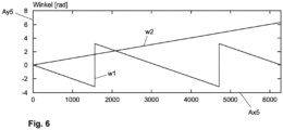
- An example of such a determined first rotor angle w1 is shown in Fig. 6 , with the samples being shown on the Ax5 axis and the angle in radians (rad) being shown on the Ay5 axis.
- a second rotor angle w2 is determined from the first rotor angle w1, which corresponds to the actual rotor angle.
- Block 20 also includes a counter by means of which the periods are counted in order to incorporate them into the correction calculation.
- the counter is initialized, taking the current settling time into account.
- the rotor position RP2 determined in this way is then provided to block 21 for the field-oriented control of the permanent magnet synchronous motor 1 as an input variable.
- the rotor position RP2 is a rotor position determined redundantly to a rotor position RP1 determined with an optional rotor position sensor unit 3. Both the rotor position RP1 determined by a sensor and the rotor position RP2 determined without a sensor are transmitted to block 21, so that in the event of a failure of the rotor position sensor unit 3, the permanent magnet synchronous motor 1 can advantageously continue to operate.
- control unit 2 has a block 22 for BEMF-based rotor position determination, wherein it is provided that the BEMF-based rotor position determination of block 22 replaces the ripple current-based rotor position determination of block 20 at a predetermined speed of the rotor of the permanent magnet synchronous motor 1.
- the BEMF-based determined rotor position RP3 is also fed to block 21 for the control of the permanent magnet synchronous motor 1.
- a permanent magnet synchronous motor 1 with a control unit 2 as in Fig. 1 shown is intended in particular for use in a motor vehicle 4, as exemplified in Fig. 7 outlined. In particular, it is intended to provide the permanent magnet synchronous motor 1 with the control unit 2 in a steering actuator 53 of a steering system 5.
- Another application is as a motor 61 in an air conditioning compressor used in a motor vehicle 4.
- Another application is as a servomotor 73 in a braking system 7 of a motor vehicle 4, wherein the servomotor sets the braking force acting on the respective brake 71.
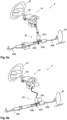
- a steering system 8 for a motor vehicle is shown.
- Fig. 8a is an electromechanical steering system 8 and in Fig. 8b a steer-by-wire steering system 8 is shown.
- the steering systems 8 each comprise a steering column 81 with a steering spindle 82 and a steering gear 83.
- the steering gear 83 comprises a pinion 835 and a rack 836, which can also be referred to as a toothed coupling rod.
- the steering gear 83 serves to translate a rotational movement of the pinion 835 into a translational movement of the rack 836 along the longitudinal axis of the rack 836.
- a steering wheel 87 is attached for inputting a driver's steering request or a steering command, wherein the driver can turn the steering wheel 87 in a known manner to input his steering request.
- the rack 836 which moves linearly along its longitudinal axis, is mechanically connected to a tie rod 838 on both sides of the motor vehicle.
- the tie rods 838 are in turn mechanically coupled to the vehicle wheels 84.
- the steering column 81 is mechanically coupled to the steered wheels 84 of the motor vehicle via the steering gear 83.
- Both the steering actuator 831 according to Fig. 8a as well as the steering actuator 831 according to Fig. 8b each comprise a permanent magnet synchronous motor 1 with a control unit 2, as described with reference to Fig. 1 explained.
Landscapes
- Engineering & Computer Science (AREA)
- Power Engineering (AREA)
- Control Of Motors That Do Not Use Commutators (AREA)
Claims (15)
- Procédé pour déterminer une position de rotor (RP2) d'un moteur synchrone à aimants permanents triphasé (1), le moteur synchrone à aimants permanents (1) présentant, par rapport à un système de coordonnées d/q présentant un axe d et un axe q, comme système de référence fixe par rapport au rotor, une inductance d'axe d (Ld) et une inductance d'axe q (Lq) différente de l'inductance d'axe d (Ld), une inductance (Lu, Lv, Lw) étant associée à chaque phase du moteur synchrone à aimants permanents (1), laquelle inductance varie en fonction de la position du rotor, et la position du rotor étant déterminée au moyen des inductances variables, où une tension (u(t)) est appliquée aux phases, la tension appliquée (u(t)) provoquant pour chaque phase respectivement un courant d'ondulation (i(t)), le courant d'ondulation (i(t)) étant déterminé pour au moins deux des trois phases et l'inductance de la phase respective étant déterminée sur la base du courant d'ondulation (i(t)) déterminé pour la phase respective, caractérisé en ce qu'un premier angle de rotor (w1) étant déterminé à partir de l'inductance déterminée pour une phase respective en utilisant une transformation de Clarke, un calcul de correction est appliqué au premier angle de rotor (w1) pour déterminer un deuxième angle de rotor (w2), et le calcul de correction tient compte d'un déroulement de période avec une alternance entre une première période et une deuxième période qui est décalée de 180° par rapport à la première période.
- Procédé selon la revendication 1, caractérisé en ce que les périodes sont comptées au moyen d'un compteur.
- Procédé selon la revendication 2, caractérisé en ce qu'une initialisation du compteur est effectuée lors du démarrage du moteur synchrone à aimants permanents (1).
- Procédé selon l'une quelconque des revendications précédentes, caractérisé en ce que le moteur synchrone à aimants permanents (1) est commandé au moyen d'un signal PWM, ledit signal PWM étant utilisé pour provoquer le courant d'ondulation (i(t)).
- Procédé selon l'une des revendications précédentes, caractérisé en ce que le moteur synchrone à aimants permanents (1) est commandé au moyen d'une modulation de pointeur spatial utilisant des pointeurs spatiaux de tension.
- Procédé selon l'une des revendications précédentes, caractérisé en ce que, pour une phase, on détermine comme courant d'ondulation (i(t)) un courant qui est provoqué par une tension d'ondulation (ur(t)) résultant de la différence de tension entre une tension instantanée (u(t)) et une tension de phase moyenne (ua(t)), la tension instantanée (u(t)) étant déterminée par le pointeur spatial de tension associé.
- Procédé selon la revendication 6, caractérisé en ce qu'un gradient du courant d'ondulation (i(t)) est déterminé pour au moins deux des trois phases, l'inductance de la phase respective étant déterminée à partir du gradient déterminé pour une phase et de la tension d'ondulation (ur(t)) qui en résulte pour cette phase.
- Procédé selon la revendication 7, dans lequel on détermine le gradient du courant d'ondulation (i(t)) pour seulement deux des trois phases et on détermine les inductances des deux phases à partir du gradient déterminé pour une phase et de la tension d'ondulation (ur(t)) qui en résulte pour cette phase, caractérisé en ce que la détermination des inductances pour les deux phases s'effectue sous le même vecteur spatial de tension, l'inductance de la troisième phase étant déterminée pour ce vecteur spatial de tension à partir des inductances déterminées pour les deux autres phases.
- Procédé selon la revendication 7 ou la revendication 8, caractérisé en ce que le gradient du courant d'ondulation (i(t)) est déterminé au moyen de la mesure du courant de phase ; et/ou
en ce que le gradient du courant d'ondulation (i(t)) est déterminé au moyen d'une mesure de courant de circuit intermédiaire. - Procédé selon l'une des revendications 7 à 9, caractérisé en ce qu'une unité de microcontrôleur est utilisée pour la commande du moteur synchrone à aimants permanents (1), des entrées d'un convertisseur analogique-numérique de l'unité de microcontrôleur étant utilisées pour une détermination du gradient du courant d'ondulation (i(t)).
- Procédé selon l'une quelconque des revendications précédentes, caractérisé en ce que, à une vitesse de rotation prédéterminée du moteur synchrone à aimants permanents (1), la position du rotor (RP3) est déterminée en utilisant un procédé basé sur la BEMF.
- Procédé selon l'une des revendications précédentes, caractérisé en ce que des signaux PWM différents sont appliqués lorsque le moteur synchrone à aimants permanents (1) est dans un état stationnaire sans charge et lorsque le moteur synchrone à aimants permanents (1) est dans un état de charge.
- Procédé de régulation orientée champ d'un moteur synchrone à aimants permanents (1), en particulier d'un moteur synchrone à aimants permanents (1) utilisé dans un véhicule automobile (4) pour un système d'assistance, une position de rotor (RP1, RP2, RP3) du moteur synchrone à aimants permanents (1) nécessaire pour la régulation orientée champ étant déterminée, caractérisé en ce que la détermination de la position de rotor est effectuée selon un procédé selon l'une des revendications 1 à 12.
- Unité de commande (2) pour le fonctionnement d'un moteur synchrone à aimants permanents (1), caractérisée en ce que l'unité de commande (2) est conçue pour la régulation orientée champ du moteur synchrone à aimants permanents (1) selon le procédé selon la revendication 13.
- Système de direction (5, 8) qui est conçu pour détecter des ordres de direction donnés par l'intermédiaire d'une manette de direction (51, 87) et les transmettre par l'intermédiaire d'un actionneur de direction (53, 831) à une crémaillère (836) sur laquelle sont disposées des roues orientables (54, 84) par l'intermédiaire de barres d'accouplement (838), l'actionneur de direction (53, 831) comprenant un moteur synchrone à aimants permanents (1), caractérisé en ce que le moteur synchrone à aimants permanents (1) comprend une unité de commande (2) selon la revendication 14.
Applications Claiming Priority (1)
| Application Number | Priority Date | Filing Date | Title |
|---|---|---|---|
| DE102021203450.0A DE102021203450A1 (de) | 2021-04-07 | 2021-04-07 | Sensorlose Bestimmung der Rotorposition bei einem Permanentmagnet-Synchronmotor |
Publications (2)
| Publication Number | Publication Date |
|---|---|
| EP4072002A1 EP4072002A1 (fr) | 2022-10-12 |
| EP4072002B1 true EP4072002B1 (fr) | 2025-05-07 |
Family
ID=76432401
Family Applications (1)
| Application Number | Title | Priority Date | Filing Date |
|---|---|---|---|
| EP22164919.7A Active EP4072002B1 (fr) | 2021-04-07 | 2022-03-29 | Détermination sans capteur de la position du rotor d'un moteur synchrone à aimants permanents |
Country Status (3)
| Country | Link |
|---|---|
| EP (1) | EP4072002B1 (fr) |
| CN (1) | CN115250082A (fr) |
| DE (1) | DE102021203450A1 (fr) |
Families Citing this family (3)
| Publication number | Priority date | Publication date | Assignee | Title |
|---|---|---|---|---|
| DE102021209436A1 (de) | 2021-08-27 | 2023-03-02 | Zf Friedrichshafen Ag | Elektrische Einrichtung für ein Kraftfahrzeug |
| DE102023203527A1 (de) * | 2023-04-18 | 2024-10-24 | Zf Friedrichshafen Ag | Bestimmung eines Rotorwinkels einer elektrischen Maschine |
| DE102023127465A1 (de) * | 2023-10-09 | 2025-04-10 | Bayerische Motoren Werke Aktiengesellschaft | Verfahren und Vorrichtung zur Ermittlung der Winkelposition des Rotors einer elektrischen Maschine |
Family Cites Families (9)
| Publication number | Priority date | Publication date | Assignee | Title |
|---|---|---|---|---|
| GB0220401D0 (en) * | 2002-09-03 | 2002-10-09 | Trw Ltd | Motor drive control |
| JP5329005B2 (ja) * | 2011-03-15 | 2013-10-30 | 三菱電機株式会社 | 永久磁石式回転電機 |
| CN103997268A (zh) * | 2014-05-28 | 2014-08-20 | 东南大学 | 一种用于变电站巡视机器人的无位置传感控制方法 |
| US10830610B2 (en) * | 2016-09-26 | 2020-11-10 | Analog Devices, Inc. | Method and apparatus for motor rotor position determination |
| CN106385215B (zh) * | 2016-09-27 | 2018-10-26 | 华中科技大学 | 一种交流电机变开关频率pwm转矩脉动控制方法 |
| JP2018153027A (ja) * | 2017-03-14 | 2018-09-27 | 株式会社東芝 | 同期電動機の回転位置推定装置,空調機及び洗濯機 |
| GB2581187A (en) * | 2019-02-07 | 2020-08-12 | Stannah Stairlifts Ltd | Electric motor control |
| DE102019202142A1 (de) | 2019-02-18 | 2020-08-20 | Thyssenkrupp Ag | Hilfskraftlenkung für ein Kraftfahrzeug |
| EP3651347B1 (fr) * | 2019-12-31 | 2021-12-01 | Pfeiffer Vacuum GmbH | Procédé de régulation d'un moteur synchrone à aimants permanents, dispositif de commande et appareil sous vide |
-
2021
- 2021-04-07 DE DE102021203450.0A patent/DE102021203450A1/de active Pending
-
2022
- 2022-03-29 EP EP22164919.7A patent/EP4072002B1/fr active Active
- 2022-04-07 CN CN202210362338.6A patent/CN115250082A/zh active Pending
Also Published As
| Publication number | Publication date |
|---|---|
| DE102021203450A1 (de) | 2021-07-08 |
| CN115250082A (zh) | 2022-10-28 |
| EP4072002A1 (fr) | 2022-10-12 |
Similar Documents
| Publication | Publication Date | Title |
|---|---|---|
| EP4072002B1 (fr) | Détermination sans capteur de la position du rotor d'un moteur synchrone à aimants permanents | |
| EP2499737B1 (fr) | Procédé de contrôle de plausibilité du couple d'une machine électrique, et régulateur de machine servant à la régulation d'une machine électrique et à la mise en oeuvre de ce procédé | |
| EP3262748B1 (fr) | Disposition des circuits et procédé de commutation sans capteur | |
| EP2194641B1 (fr) | Système de détermination de la position initiale des pôles du rotor d'un moteur électrique | |
| DE10312199B4 (de) | Elektrische Servolenkungsvorrichtung und zugehöriges Steuer- /Regelverfahren | |
| DE102016212924A1 (de) | Leistungswandler | |
| DE102008058434A1 (de) | Motoransteuerungsvorrichtung und -verfahren für ein elektrisches Kraftlenksystem | |
| DE102005052015B4 (de) | Motorsteuerung und Lenkvorrichtung | |
| DE10205755A1 (de) | Elektrisches Servolenkungssteuersystem und dessen Steuerverfahren | |
| EP2348630B1 (fr) | Circuit de commande pour moteur triphasé | |
| DE10226974A1 (de) | Verfahren und Vorrichtung zur Bestimmung einer Rotorlage einer feldorientiert betriebenen Drehfeldmaschine ohne mechanischen Sensor | |
| EP1699676B1 (fr) | Procede de ralentissement d'un moteur electrique et mecanisme d'entrainement electrique | |
| WO2018072778A1 (fr) | Procédé de correction des erreurs de mesure d'un capteur de rotation sinus-consinus | |
| DE102011088242A1 (de) | Verfahren zum Betrieb einer Drehfeldmaschine | |
| EP2555417B1 (fr) | Détermination de l'angle d'un rotor d'un moteur électrique dans un véhicule équipé de capteurs de roue | |
| WO2021074094A1 (fr) | Procédé de fonctionnement d'un moteur électrique polyphasé sans balai et sans capteur | |
| DE10333414A1 (de) | Verfahren zum Betrieb einer motorischen Positionierungsvorrichtung sowie zugehörige Positionierungsvorrichtung | |
| EP3016270A2 (fr) | Procédé et système de circuit de stabilisation de la position d'un rotor par rapport à un stator dans un moteur électrique | |
| DE102010040223A1 (de) | Verfahren zum Betrieb einer Drehfeldmaschine | |
| DE10338996A1 (de) | Verfahren zur Steuerung eines bürstenlosen Elektromotors | |
| DE102012213386A1 (de) | Verfahren zum Betrieb einer Drehfeldmaschine | |
| EP3098960B1 (fr) | Procede destine au fonctionnement d'une machine electrique et entrainement | |
| EP4224704B1 (fr) | Machine électrique commutée électroniquement comprenant plusieurs machines partielles et procédé de fonctionnement d'une telle machine électrique | |
| DE102020201087A1 (de) | Verfahren und Vorrichtung zum Betreiben einer Elektromaschine, Antriebseinrichtung | |
| DE102005050591B4 (de) | Wechselstrom-Servotreiber |
Legal Events
| Date | Code | Title | Description |
|---|---|---|---|
| PUAI | Public reference made under article 153(3) epc to a published international application that has entered the european phase |
Free format text: ORIGINAL CODE: 0009012 |
|
| STAA | Information on the status of an ep patent application or granted ep patent |
Free format text: STATUS: THE APPLICATION HAS BEEN PUBLISHED |
|
| AK | Designated contracting states |
Kind code of ref document: A1 Designated state(s): AL AT BE BG CH CY CZ DE DK EE ES FI FR GB GR HR HU IE IS IT LI LT LU LV MC MK MT NL NO PL PT RO RS SE SI SK SM TR |
|
| RAP3 | Party data changed (applicant data changed or rights of an application transferred) |
Owner name: THYSSENKRUPP AG Owner name: THYSSENKRUPP PRESTA AG |
|
| STAA | Information on the status of an ep patent application or granted ep patent |
Free format text: STATUS: REQUEST FOR EXAMINATION WAS MADE |
|
| 17P | Request for examination filed |
Effective date: 20230412 |
|
| RBV | Designated contracting states (corrected) |
Designated state(s): AL AT BE BG CH CY CZ DE DK EE ES FI FR GB GR HR HU IE IS IT LI LT LU LV MC MK MT NL NO PL PT RO RS SE SI SK SM TR |
|
| GRAP | Despatch of communication of intention to grant a patent |
Free format text: ORIGINAL CODE: EPIDOSNIGR1 |
|
| STAA | Information on the status of an ep patent application or granted ep patent |
Free format text: STATUS: GRANT OF PATENT IS INTENDED |
|
| RIC1 | Information provided on ipc code assigned before grant |
Ipc: H02P 21/24 20160101ALI20241104BHEP Ipc: H02P 6/185 20160101AFI20241104BHEP |
|
| INTG | Intention to grant announced |
Effective date: 20241125 |
|
| GRAS | Grant fee paid |
Free format text: ORIGINAL CODE: EPIDOSNIGR3 |
|
| GRAA | (expected) grant |
Free format text: ORIGINAL CODE: 0009210 |
|
| STAA | Information on the status of an ep patent application or granted ep patent |
Free format text: STATUS: THE PATENT HAS BEEN GRANTED |
|
| AK | Designated contracting states |
Kind code of ref document: B1 Designated state(s): AL AT BE BG CH CY CZ DE DK EE ES FI FR GB GR HR HU IE IS IT LI LT LU LV MC MK MT NL NO PL PT RO RS SE SI SK SM TR |
|
| REG | Reference to a national code |
Ref country code: GB Ref legal event code: FG4D Free format text: NOT ENGLISH |
|
| REG | Reference to a national code |
Ref country code: CH Ref legal event code: EP |
|
| REG | Reference to a national code |
Ref country code: DE Ref legal event code: R096 Ref document number: 502022003836 Country of ref document: DE |
|
| REG | Reference to a national code |
Ref country code: IE Ref legal event code: FG4D Free format text: LANGUAGE OF EP DOCUMENT: GERMAN |
|
| REG | Reference to a national code |
Ref country code: DE Ref legal event code: R084 Ref document number: 502022003836 Country of ref document: DE |
|
| REG | Reference to a national code |
Ref country code: DE Ref legal event code: R083 Ref document number: 502022003836 Country of ref document: DE |
|
| REG | Reference to a national code |
Ref country code: NL Ref legal event code: MP Effective date: 20250507 |
|
| PG25 | Lapsed in a contracting state [announced via postgrant information from national office to epo] |
Ref country code: FI Free format text: LAPSE BECAUSE OF FAILURE TO SUBMIT A TRANSLATION OF THE DESCRIPTION OR TO PAY THE FEE WITHIN THE PRESCRIBED TIME-LIMIT Effective date: 20250507 Ref country code: ES Free format text: LAPSE BECAUSE OF FAILURE TO SUBMIT A TRANSLATION OF THE DESCRIPTION OR TO PAY THE FEE WITHIN THE PRESCRIBED TIME-LIMIT Effective date: 20250507 Ref country code: PT Free format text: LAPSE BECAUSE OF FAILURE TO SUBMIT A TRANSLATION OF THE DESCRIPTION OR TO PAY THE FEE WITHIN THE PRESCRIBED TIME-LIMIT Effective date: 20250908 |
|
| REG | Reference to a national code |
Ref country code: LT Ref legal event code: MG9D |
|
| PG25 | Lapsed in a contracting state [announced via postgrant information from national office to epo] |
Ref country code: NO Free format text: LAPSE BECAUSE OF FAILURE TO SUBMIT A TRANSLATION OF THE DESCRIPTION OR TO PAY THE FEE WITHIN THE PRESCRIBED TIME-LIMIT Effective date: 20250807 Ref country code: GR Free format text: LAPSE BECAUSE OF FAILURE TO SUBMIT A TRANSLATION OF THE DESCRIPTION OR TO PAY THE FEE WITHIN THE PRESCRIBED TIME-LIMIT Effective date: 20250808 |
|
| PG25 | Lapsed in a contracting state [announced via postgrant information from national office to epo] |
Ref country code: NL Free format text: LAPSE BECAUSE OF FAILURE TO SUBMIT A TRANSLATION OF THE DESCRIPTION OR TO PAY THE FEE WITHIN THE PRESCRIBED TIME-LIMIT Effective date: 20250507 Ref country code: PL Free format text: LAPSE BECAUSE OF FAILURE TO SUBMIT A TRANSLATION OF THE DESCRIPTION OR TO PAY THE FEE WITHIN THE PRESCRIBED TIME-LIMIT Effective date: 20250507 |
|
| PG25 | Lapsed in a contracting state [announced via postgrant information from national office to epo] |
Ref country code: BG Free format text: LAPSE BECAUSE OF FAILURE TO SUBMIT A TRANSLATION OF THE DESCRIPTION OR TO PAY THE FEE WITHIN THE PRESCRIBED TIME-LIMIT Effective date: 20250507 |
|
| PG25 | Lapsed in a contracting state [announced via postgrant information from national office to epo] |
Ref country code: HR Free format text: LAPSE BECAUSE OF FAILURE TO SUBMIT A TRANSLATION OF THE DESCRIPTION OR TO PAY THE FEE WITHIN THE PRESCRIBED TIME-LIMIT Effective date: 20250507 |
|
| PG25 | Lapsed in a contracting state [announced via postgrant information from national office to epo] |
Ref country code: RS Free format text: LAPSE BECAUSE OF FAILURE TO SUBMIT A TRANSLATION OF THE DESCRIPTION OR TO PAY THE FEE WITHIN THE PRESCRIBED TIME-LIMIT Effective date: 20250807 |
|
| PG25 | Lapsed in a contracting state [announced via postgrant information from national office to epo] |
Ref country code: IS Free format text: LAPSE BECAUSE OF FAILURE TO SUBMIT A TRANSLATION OF THE DESCRIPTION OR TO PAY THE FEE WITHIN THE PRESCRIBED TIME-LIMIT Effective date: 20250907 |
|
| PG25 | Lapsed in a contracting state [announced via postgrant information from national office to epo] |
Ref country code: LV Free format text: LAPSE BECAUSE OF FAILURE TO SUBMIT A TRANSLATION OF THE DESCRIPTION OR TO PAY THE FEE WITHIN THE PRESCRIBED TIME-LIMIT Effective date: 20250507 |
|
| PG25 | Lapsed in a contracting state [announced via postgrant information from national office to epo] |
Ref country code: SM Free format text: LAPSE BECAUSE OF FAILURE TO SUBMIT A TRANSLATION OF THE DESCRIPTION OR TO PAY THE FEE WITHIN THE PRESCRIBED TIME-LIMIT Effective date: 20250507 Ref country code: DK Free format text: LAPSE BECAUSE OF FAILURE TO SUBMIT A TRANSLATION OF THE DESCRIPTION OR TO PAY THE FEE WITHIN THE PRESCRIBED TIME-LIMIT Effective date: 20250507 |
|
| PG25 | Lapsed in a contracting state [announced via postgrant information from national office to epo] |
Ref country code: CZ Free format text: LAPSE BECAUSE OF FAILURE TO SUBMIT A TRANSLATION OF THE DESCRIPTION OR TO PAY THE FEE WITHIN THE PRESCRIBED TIME-LIMIT Effective date: 20250507 |
|
| PG25 | Lapsed in a contracting state [announced via postgrant information from national office to epo] |
Ref country code: EE Free format text: LAPSE BECAUSE OF FAILURE TO SUBMIT A TRANSLATION OF THE DESCRIPTION OR TO PAY THE FEE WITHIN THE PRESCRIBED TIME-LIMIT Effective date: 20250507 |
|
| PG25 | Lapsed in a contracting state [announced via postgrant information from national office to epo] |
Ref country code: SK Free format text: LAPSE BECAUSE OF FAILURE TO SUBMIT A TRANSLATION OF THE DESCRIPTION OR TO PAY THE FEE WITHIN THE PRESCRIBED TIME-LIMIT Effective date: 20250507 |
|
| PG25 | Lapsed in a contracting state [announced via postgrant information from national office to epo] |
Ref country code: IT Free format text: LAPSE BECAUSE OF FAILURE TO SUBMIT A TRANSLATION OF THE DESCRIPTION OR TO PAY THE FEE WITHIN THE PRESCRIBED TIME-LIMIT Effective date: 20250507 |
|
| REG | Reference to a national code |
Ref country code: DE Ref legal event code: R097 Ref document number: 502022003836 Country of ref document: DE |
|
| PLBE | No opposition filed within time limit |
Free format text: ORIGINAL CODE: 0009261 |
|
| STAA | Information on the status of an ep patent application or granted ep patent |
Free format text: STATUS: NO OPPOSITION FILED WITHIN TIME LIMIT |
|
| REG | Reference to a national code |
Ref country code: CH Ref legal event code: L10 Free format text: ST27 STATUS EVENT CODE: U-0-0-L10-L00 (AS PROVIDED BY THE NATIONAL OFFICE) Effective date: 20260318 |
|
| PGFP | Annual fee paid to national office [announced via postgrant information from national office to epo] |
Ref country code: GB Payment date: 20260324 Year of fee payment: 5 |
|
| PGFP | Annual fee paid to national office [announced via postgrant information from national office to epo] |
Ref country code: DE Payment date: 20260319 Year of fee payment: 5 |
|
| PGFP | Annual fee paid to national office [announced via postgrant information from national office to epo] |
Ref country code: AT Payment date: 20260301 Year of fee payment: 5 |
|
| 26N | No opposition filed |
Effective date: 20260210 |
|
| PGFP | Annual fee paid to national office [announced via postgrant information from national office to epo] |
Ref country code: FR Payment date: 20260323 Year of fee payment: 5 |