EP4071901A1 - Battery pack - Google Patents
Battery pack Download PDFInfo
- Publication number
- EP4071901A1 EP4071901A1 EP20895577.3A EP20895577A EP4071901A1 EP 4071901 A1 EP4071901 A1 EP 4071901A1 EP 20895577 A EP20895577 A EP 20895577A EP 4071901 A1 EP4071901 A1 EP 4071901A1
- Authority
- EP
- European Patent Office
- Prior art keywords
- outer case
- drain hole
- battery
- battery pack
- tubular body
- Prior art date
- Legal status (The legal status is an assumption and is not a legal conclusion. Google has not performed a legal analysis and makes no representation as to the accuracy of the status listed.)
- Pending
Links
- 238000004891 communication Methods 0.000 claims abstract description 21
- 230000036544 posture Effects 0.000 claims description 9
- 239000000126 substance Substances 0.000 abstract description 35
- 239000007789 gas Substances 0.000 description 15
- XLYOFNOQVPJJNP-UHFFFAOYSA-N water Substances O XLYOFNOQVPJJNP-UHFFFAOYSA-N 0.000 description 9
- 238000007599 discharging Methods 0.000 description 6
- 239000012212 insulator Substances 0.000 description 5
- 229910052751 metal Inorganic materials 0.000 description 5
- 239000002184 metal Substances 0.000 description 5
- 238000003466 welding Methods 0.000 description 5
- 229910052782 aluminium Inorganic materials 0.000 description 4
- XAGFODPZIPBFFR-UHFFFAOYSA-N aluminium Chemical compound [Al] XAGFODPZIPBFFR-UHFFFAOYSA-N 0.000 description 4
- 238000009434 installation Methods 0.000 description 4
- 239000000463 material Substances 0.000 description 4
- HBBGRARXTFLTSG-UHFFFAOYSA-N Lithium ion Chemical compound [Li+] HBBGRARXTFLTSG-UHFFFAOYSA-N 0.000 description 3
- 229910001416 lithium ion Inorganic materials 0.000 description 3
- 229910000838 Al alloy Inorganic materials 0.000 description 2
- 239000004743 Polypropylene Substances 0.000 description 2
- 230000002708 enhancing effect Effects 0.000 description 2
- 229920001155 polypropylene Polymers 0.000 description 2
- 239000011347 resin Substances 0.000 description 2
- 229920005989 resin Polymers 0.000 description 2
- 238000007789 sealing Methods 0.000 description 2
- 229910001111 Fine metal Inorganic materials 0.000 description 1
- 230000000712 assembly Effects 0.000 description 1
- 238000000429 assembly Methods 0.000 description 1
- QVGXLLKOCUKJST-UHFFFAOYSA-N atomic oxygen Chemical compound [O] QVGXLLKOCUKJST-UHFFFAOYSA-N 0.000 description 1
- YACLQRRMGMJLJV-UHFFFAOYSA-N chloroprene Chemical compound ClC(=C)C=C YACLQRRMGMJLJV-UHFFFAOYSA-N 0.000 description 1
- 230000000052 comparative effect Effects 0.000 description 1
- 239000000470 constituent Substances 0.000 description 1
- 230000008094 contradictory effect Effects 0.000 description 1
- 230000000694 effects Effects 0.000 description 1
- 230000005611 electricity Effects 0.000 description 1
- 230000006355 external stress Effects 0.000 description 1
- 239000006260 foam Substances 0.000 description 1
- 239000011810 insulating material Substances 0.000 description 1
- 238000009413 insulation Methods 0.000 description 1
- 239000011159 matrix material Substances 0.000 description 1
- 239000007769 metal material Substances 0.000 description 1
- 239000002923 metal particle Substances 0.000 description 1
- 238000000034 method Methods 0.000 description 1
- 239000001301 oxygen Substances 0.000 description 1
- 229910052760 oxygen Inorganic materials 0.000 description 1
- 239000004033 plastic Substances 0.000 description 1
- 229920000515 polycarbonate Polymers 0.000 description 1
- 239000004417 polycarbonate Substances 0.000 description 1
- -1 polypropylene Polymers 0.000 description 1
- 230000002250 progressing effect Effects 0.000 description 1
- 230000001681 protective effect Effects 0.000 description 1
- 239000007787 solid Substances 0.000 description 1
- 230000001629 suppression Effects 0.000 description 1
Images


Classifications
-
- H—ELECTRICITY
- H01—ELECTRIC ELEMENTS
- H01M—PROCESSES OR MEANS, e.g. BATTERIES, FOR THE DIRECT CONVERSION OF CHEMICAL ENERGY INTO ELECTRICAL ENERGY
- H01M50/00—Constructional details or processes of manufacture of the non-active parts of electrochemical cells other than fuel cells, e.g. hybrid cells
- H01M50/30—Arrangements for facilitating escape of gases
- H01M50/35—Gas exhaust passages comprising elongated, tortuous or labyrinth-shaped exhaust passages
- H01M50/367—Internal gas exhaust passages forming part of the battery cover or case; Double cover vent systems
-
- H—ELECTRICITY
- H01—ELECTRIC ELEMENTS
- H01M—PROCESSES OR MEANS, e.g. BATTERIES, FOR THE DIRECT CONVERSION OF CHEMICAL ENERGY INTO ELECTRICAL ENERGY
- H01M50/00—Constructional details or processes of manufacture of the non-active parts of electrochemical cells other than fuel cells, e.g. hybrid cells
- H01M50/60—Arrangements or processes for filling or topping-up with liquids; Arrangements or processes for draining liquids from casings
- H01M50/691—Arrangements or processes for draining liquids from casings; Cleaning battery or cell casings
-
- H—ELECTRICITY
- H01—ELECTRIC ELEMENTS
- H01M—PROCESSES OR MEANS, e.g. BATTERIES, FOR THE DIRECT CONVERSION OF CHEMICAL ENERGY INTO ELECTRICAL ENERGY
- H01M50/00—Constructional details or processes of manufacture of the non-active parts of electrochemical cells other than fuel cells, e.g. hybrid cells
- H01M50/20—Mountings; Secondary casings or frames; Racks, modules or packs; Suspension devices; Shock absorbers; Transport or carrying devices; Holders
- H01M50/233—Mountings; Secondary casings or frames; Racks, modules or packs; Suspension devices; Shock absorbers; Transport or carrying devices; Holders characterised by physical properties of casings or racks, e.g. dimensions
- H01M50/24—Mountings; Secondary casings or frames; Racks, modules or packs; Suspension devices; Shock absorbers; Transport or carrying devices; Holders characterised by physical properties of casings or racks, e.g. dimensions adapted for protecting batteries from their environment, e.g. from corrosion
-
- H—ELECTRICITY
- H01—ELECTRIC ELEMENTS
- H01M—PROCESSES OR MEANS, e.g. BATTERIES, FOR THE DIRECT CONVERSION OF CHEMICAL ENERGY INTO ELECTRICAL ENERGY
- H01M50/00—Constructional details or processes of manufacture of the non-active parts of electrochemical cells other than fuel cells, e.g. hybrid cells
- H01M50/20—Mountings; Secondary casings or frames; Racks, modules or packs; Suspension devices; Shock absorbers; Transport or carrying devices; Holders
- H01M50/204—Racks, modules or packs for multiple batteries or multiple cells
-
- H—ELECTRICITY
- H01—ELECTRIC ELEMENTS
- H01M—PROCESSES OR MEANS, e.g. BATTERIES, FOR THE DIRECT CONVERSION OF CHEMICAL ENERGY INTO ELECTRICAL ENERGY
- H01M50/00—Constructional details or processes of manufacture of the non-active parts of electrochemical cells other than fuel cells, e.g. hybrid cells
- H01M50/20—Mountings; Secondary casings or frames; Racks, modules or packs; Suspension devices; Shock absorbers; Transport or carrying devices; Holders
- H01M50/244—Secondary casings; Racks; Suspension devices; Carrying devices; Holders characterised by their mounting method
-
- H—ELECTRICITY
- H01—ELECTRIC ELEMENTS
- H01M—PROCESSES OR MEANS, e.g. BATTERIES, FOR THE DIRECT CONVERSION OF CHEMICAL ENERGY INTO ELECTRICAL ENERGY
- H01M50/00—Constructional details or processes of manufacture of the non-active parts of electrochemical cells other than fuel cells, e.g. hybrid cells
- H01M50/20—Mountings; Secondary casings or frames; Racks, modules or packs; Suspension devices; Shock absorbers; Transport or carrying devices; Holders
- H01M50/247—Mountings; Secondary casings or frames; Racks, modules or packs; Suspension devices; Shock absorbers; Transport or carrying devices; Holders specially adapted for portable devices, e.g. mobile phones, computers, hand tools or pacemakers
-
- H—ELECTRICITY
- H01—ELECTRIC ELEMENTS
- H01M—PROCESSES OR MEANS, e.g. BATTERIES, FOR THE DIRECT CONVERSION OF CHEMICAL ENERGY INTO ELECTRICAL ENERGY
- H01M50/00—Constructional details or processes of manufacture of the non-active parts of electrochemical cells other than fuel cells, e.g. hybrid cells
- H01M50/30—Arrangements for facilitating escape of gases
- H01M50/317—Re-sealable arrangements
-
- H—ELECTRICITY
- H01—ELECTRIC ELEMENTS
- H01M—PROCESSES OR MEANS, e.g. BATTERIES, FOR THE DIRECT CONVERSION OF CHEMICAL ENERGY INTO ELECTRICAL ENERGY
- H01M50/00—Constructional details or processes of manufacture of the non-active parts of electrochemical cells other than fuel cells, e.g. hybrid cells
- H01M50/50—Current conducting connections for cells or batteries
- H01M50/502—Interconnectors for connecting terminals of adjacent batteries; Interconnectors for connecting cells outside a battery casing
- H01M50/507—Interconnectors for connecting terminals of adjacent batteries; Interconnectors for connecting cells outside a battery casing comprising an arrangement of two or more busbars within a container structure, e.g. busbar modules
-
- H—ELECTRICITY
- H01—ELECTRIC ELEMENTS
- H01M—PROCESSES OR MEANS, e.g. BATTERIES, FOR THE DIRECT CONVERSION OF CHEMICAL ENERGY INTO ELECTRICAL ENERGY
- H01M50/00—Constructional details or processes of manufacture of the non-active parts of electrochemical cells other than fuel cells, e.g. hybrid cells
- H01M50/20—Mountings; Secondary casings or frames; Racks, modules or packs; Suspension devices; Shock absorbers; Transport or carrying devices; Holders
- H01M50/204—Racks, modules or packs for multiple batteries or multiple cells
- H01M50/207—Racks, modules or packs for multiple batteries or multiple cells characterised by their shape
- H01M50/213—Racks, modules or packs for multiple batteries or multiple cells characterised by their shape adapted for cells having curved cross-section, e.g. round or elliptic
-
- Y—GENERAL TAGGING OF NEW TECHNOLOGICAL DEVELOPMENTS; GENERAL TAGGING OF CROSS-SECTIONAL TECHNOLOGIES SPANNING OVER SEVERAL SECTIONS OF THE IPC; TECHNICAL SUBJECTS COVERED BY FORMER USPC CROSS-REFERENCE ART COLLECTIONS [XRACs] AND DIGESTS
- Y02—TECHNOLOGIES OR APPLICATIONS FOR MITIGATION OR ADAPTATION AGAINST CLIMATE CHANGE
- Y02E—REDUCTION OF GREENHOUSE GAS [GHG] EMISSIONS, RELATED TO ENERGY GENERATION, TRANSMISSION OR DISTRIBUTION
- Y02E60/00—Enabling technologies; Technologies with a potential or indirect contribution to GHG emissions mitigation
- Y02E60/10—Energy storage using batteries
Definitions
- the present invention relates to a battery pack.
- a battery pack is used as a power source for an electric assist bicycle, an electric motorcycle, an electric tool, an electric cleaner, and the like.
- a large number of rechargeable battery cells are connected in series or in parallel, and are housed in an outer case.
- Such a battery pack is used not only indoors but also outdoors.
- a through-hole opens in the outer case as a drain hole for discharging, to the outside, water unintentionally entering the outer case or as a discharge hole for discharging air in the outer case or a gas discharged from the battery to the outside (see PTL 1).
- a combustible substance such as a combustible metal piece, may be released in addition to a high-temperature gas due to external stress, an electrical short circuit, or the like.
- the combustible substance may un desirably be ignited.
- a release material may be released from the drain hole to the outside of the outer case.
- An object of the present invention is to provide a battery pack that prevents a combustible substance from leaking to the outside of the battery pack through a drain hole opening in an outer case.
- a battery pack is a battery pack that includes an outer case and one or more battery cells housed inside the outer case. Each battery includes a safety valve.
- a drain hole communicating with the inside of the outer case is provided in a part of the outer case.
- a tubular body extends to the inside of the outer case from the drain hole. One opening end of the tubular body is at the drain hole. Another opening end of the tubular body as an internal communication port opens to the inside of the outer case.
- a wall portion is provided apart from the internal communication port in an extending direction with respect to the internal communication port, the extending direction being directed toward the internal communication port from the drain hole.
- the tubular body and the wall portion block a path through the tubular body and prevents the combustible substance from being directly released from the drain hole to the outside of the battery pack while maintaining the configuration in which the water stored in the outer case is discharged to the outside through the drain hole, thus enhancing safety.
- a battery pack according to an aspect of the present invention may have the following configurations in addition to the above-described configuration.
- the tubular body has a rectangular tubular shape.
- the tubular body and the wall portion are be formed integrally with the outer case.
- the drain hole opens in a side surface of a lower part of the outer case.
- the drain hole is provided in each of left and right side surfaces of the outer case, and the drain hole provided in each of left and right side surfaces includes the tubular body and the wall portion.
- the battery pack further includes a battery holder holding the one or more battery cells at predetermined postures and plural lead plates electrically connected to a positive electrode terminal and a negative electrode terminal of each of the one or more battery cells on a side surface of the battery holder.
- the safety valve is provided on a positive electrode terminal side of each of the one or more battery cells.
- respective elements constituting the present invention may be configured such that the plurality of elements are constituted of the same members to form one member that functions as a plurality of elements, or conversely, the function of one member can be shared and achieved by a plurality of members.
- the content described in some of examples and exemplary embodiments may be applicable to other examples and exemplary embodiments.
- the battery pack described below is mainly used as a power supply device that supplies driving power to a motor for an electric assist bicycle
- the battery pack may be applied to a driving power supply of another power supply device, for example, an electric tool or an electric cleaner, or a driving power supply of an electric vehicle such as an electric scooter, an electric cart, or an electric automobile.
- exemplary Embodiment 1
- FIGS. 1 to 3 illustrate a battery pack according to Exemplary Embodiment 1.
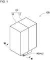
- FIG. 1 is a perspective view of battery pack 100 according to the embodiment of the present invention.
- FIG. 2 is an exploded perspective view of battery pack 100 shown in FIG. 1 .
- FIG. 3 is an exploded perspective view of the battery pack shown in FIG. 2 .
- Battery pack 100 shown in these drawings includes battery assembly 20 housed in outer case 10.
- Battery assembly 20 includes one or more battery cells 1 and battery holder 21 holding battery cells 1.
- Battery holder 21 is configured to hold one or more battery cells 1 at fixed positions. In this example, plural battery cells 1 are held by battery holder 21.
- Each battery cell 1 includes an exterior can with a tubular shape extended in one direction.
- a safety valve configured to discharges gas when an internal pressure rises is provided on one end surface of the tubular shape of the exterior can.
- Outer case 10 houses battery holder 21 therein.
- Outer case 10 illustrated in FIGS. 1 and 2 includes first case 11 with a box shape and second case 12 with a box shape into which the case 10 is divided in front and rear directions. Cases 11 and 12 are connected to each other at opening end edges thereof, and hose battery holder 21 in insides thereof.
- Outer case 10 is molded with resin of insulating material, such as polycarbonate (PC) or polypropylene (PP).
- Outer case 10 may have any shape, such as a cylindrical shape, other than the illustrated box shape.
- Outer case 10 houses battery assembly 20 therein.
- Battery assembly 20 includes one or more battery cells 1 and battery holder 21 holding battery cells 1. As shown in FIGS. 2 and 3 , in battery holder 21, plural battery cells 1 are arranged in postures parallel to one another while respective both ends of the cells are flush with one another.
- Lead plates 24 are connected to electrode terminals at both ends of each battery cell 1.
- Lead plate 24 is a current collecting terminal made of a metal plate or the like.
- Battery cell 1 is a lithium ion battery with a cylindrical shape. Lithium ion batteries have a large capacity with respect to a size and a weight, and increase a total capacity of the battery pack. However, the battery pack of the present invention does not specify the battery cell as the lithium ion battery. As the battery cell, another rechargeable, secondary battery may be used. In battery pack 100 shown in FIG. 3 , battery cell 1 is a cylindrical battery cell, but a rectangular battery cell may be used as the battery cell. Lead plates 24 are welded to the electrode terminals at both the ends of each battery cell 1 to connect adjacent battery cells 1 in series or in parallel.
- discharge port 1b of the safety valve configured to open at a predetermined pressure is provided on an end surface of the cell.
- the safety valve is a discharge valve configured to open when the inside of the exterior can of battery cell 1 has a high pressure for some reason and discharges a substance, such as a high pressure gas or a metal piece, inside to the outside.
- the electrode terminals are provided at both the ends of battery cell 1.
- an opening of the exterior can made of metal, such as aluminum, is air-tightly sealed with a sealing plate.
- a protrusion electrode is provided on the sealing plate to form a first electrode terminal, and a bottom surface of the exterior can is a second electrode terminal.
- Discharge port 1b of the safety valve is provided on the protrusion electrode side or is provided on the bottom surface of the exterior can.
- the safety valve is provided on positive electrode 1a side of the electrode terminals of battery cell 1.
- Battery holder 21 holds battery cells 1 in postures parallel to one another, such that battery cells 1 are arranged in a zigzag or matrix when viewed from a side surface of battery holder 21 while the electrode terminals are flush with one another.
- Battery holder 21 is divided into two, a pair of sub-holders 22, and holds battery cells 1 sandwiched between the pair of sub-holders 22 from the left and right.
- Each sub-holder 22 forms a housing cylinder that houses cylindrical battery cells 1.
- Battery holder 21 is made of material having excellent insulation properties, for example, resin, such as plastic.
- Circuit board 27 on which a charge and discharge circuit for controlling charge and discharge of battery cells 1, a protective circuit, and the like are mounted is arranged on one surface of battery assembly 20.
- Lead plates 24 connect cylindrical battery cells 1 arranged in plural stages and plural rows in a predetermined arrangement to one another.
- Lead plates 24 connect cylindrical battery cells 1 in parallel, in series, or in series and in parallel to one another.
- Lead plate 24 connecting the end surfaces may be formed as one sheet, or may be divided into plural sheets on each side surface in which the end surfaces of battery cells 1 are arranged on the same plane,.
- Lead plate 24 is a metal plate and is electrically connected to end-surface electrodes of the cylindrical batteries by performing ultrasonic welding, resistance welding, or laser welding.
- lead plate 24 is made of aluminum or aluminum alloy and the exterior can of the cylindrical battery is made of aluminum or aluminum alloy, since an electrical resistance of aluminum is low, connection by resistance welding becomes difficult.
- lead plate 24 is welded to the end-face electrodes preferably by ultrasonic welding.
- a fuse link that is melted by heat of a discharge gas injected from discharge port 1b upon the safety valve opening may be provided in lead plate 24.
- Lead plate 24 may form the fuse link by connecting a connecting part connected to the protrusion electrode and a main body of lead plate 24 with an elongated connecting part. In this structure, when the discharge gas is discharged, unintended energization or the like can be avoided to enhance safety by providing the fuse link that fuses lead plate 24.
- Heat insulator 26 may be disposed on lead plate 24.
- heat insulator 26 When the inside of any one of battery cells 1 has high pressure and the safety valve opens, heat insulator 26 functions as a backflow suppression layer that suppresses occurrence of catching fire due to scattering of a high-temperature and high-pressure gas and a combustible substance discharged from discharge port 1b of the safety valve and adhesion to another battery cell 1. Rubber such as chloroprene or a foam is suitably used for heat insulator 26.
- Outer case 10 has drain holes 14 therein for discharging water stored therein to the outside. Drain holes 14 open to a side surface of the case configured to face a lower surface in a posture in which outer case 10 is in a use state, for example, in a posture in which battery pack 100 is set in a power supply apparatus. In the example of FIG. 1 , since a portion protruding in a block shape is formed on the lower surface of outer case 10 and the block-shaped portion is positioned at a lowermost position in outer case 10, drain holes 14 open to a side surface of the block-shaped portion.
- drain holes 14 open to the left and right, and water is efficiently discharged from left and right drain holes 14a and 14b to the outside of outer case 10.
- the positions and the number of drain holes are not limited to this configuration.
- the drain holes may open to front and rear side surfaces, may be opened at plural locations on left and right side surfaces, or may open to only one of the side surfaces.
- tubular body 15 is provides inside outer case 10 to communicate with drain holes 14.
- Wall portion 16 is disposed at a position facing an inner communication port that is another opening end of tubular body 15.
- Outer case 10 is shown in FIGS. 4 to 8 .
- FIG. 4 is a transparent perspective view of the case for showing a part around drain hole 14 of battery pack 100 shown in FIG. 1 .
- FIG. 5 is a perspective view of the case for showing an inner surface side of outer case 10 shown in FIG. 2 .
- FIG. 6 is a perspective view of outer case 10 shown in FIG. 5 when viewed from a bottom surface side.
- FIG. 7 is a cross-sectional perspective view of outer case 10 along line VII-VII shown in FIG. 6 .
- FIG. 8 is a cross-sectional view of battery pack 100 taken along line VIII-VIII shown in in FIG. 1 .
- a safety valve opens to release a combustible substance together with a high-temperature and high-pressure gas, the combustible substance may be directly released from drain hole 914 to the outside of battery pack 900 as shown in FIG. 9 .
- the combustible substance may be ignited by a spark or the like to become a flame.
- this method restricts an installation position and an installation posture of a battery holder or the like holding the battery cell, accordingly impairing a degree of freedom in design.
- the conventional battery pack is not preferable.
- an arrangement direction of the battery cell and the battery holder may previously determined, and the battery cell and the battery holder may not be arranged not to face drain hole 914.
- the inventors of the present invention examined a configuration of battery pack 800 shown in FIG. 10 .
- tubular body 815 extends inside the exterior communicates with drain hole 814.
- Drain hole 814 has a posture opening only in a horizontal direction (lateral direction in FIG. 10 ).
- this configuration causes the combustible substance to be blocked by tubular body 815, and a situation in which the combustible substance is directly discharged from drain hole 814 to the outside is eliminated (an arrow indicated by a broken line in FIG. 10 ).
- the combustible substance is a solid having a mass of fine metal particles or the like, straightness is strong as compared with a gas having no mass. Accordingly, the periphery of the opening end is covered with tubular body 815, and thus, it is possible to effectively block the combustible substance directly coming flying and to accumulate the combustible substance inside the outer case.
- the high-temperature and high-pressure gas easily changes a traveling direction as compared with a mass combustible substance, and can be released to the outside of battery pack 800 from drain hole 814. As a result, it is possible to avoid a situation in which the high-pressure gas accumulates and expands in the outer case. Drain hole 814 opens, and thus, the water stored in the outer case can still be discharged from drain hole 814.
- drain hole 814 covered with tubular body 815 opens only in the horizontal direction.
- the combustible substance travels in the horizontal direction, the combustible substance is still discharged to the outside (an arrow indicated by a solid line in FIG. 10 indicates a flying direction of the combustible substance).
- wall portion 16a is provided at a position apart from the inner communication port in an extending direction with respect to the internal communication port, the extending direction being directed toward the internal communication port from the drain hole. Wall portion 16a prevents a progress along the extending direction of the inner communication port.
- tubular body 15 and wall portion 16a which crosses an axis along an opening direction of tubular body 15 prevent the combustible substance from being directly released from drain hole 14 to the outside of battery pack 100.
- This configuration prevents the flame from being released from drain hole 14 of battery pack 100, and causes the combustible substance to be stored inside battery pack 100 by being reflected by the surface of tubular body 15 and wall portion 16a or another member inside the exterior can, or to be discharged to the outside in a state where the strength of the combustible substance is weakened.
- the combustible substance is a metal material having a mass, the combustible substance has strong straightness, is inhibited from progressing by collision, and can suppress strength.
- this configuration maintains a function of discharging the water stored in battery pack 100 to the outside through drain holes 14, providing both contradictory characteristics of discharging the water while the combustible substance is discharged.
- tubular body 15 is extended from drain hole 14 to the inside of outer case 10.
- Tubular body 15 has one opening end as drain hole 14 and the other opening end as the internal communication port.
- the inner communication port opens to the inside of outer case 10.
- tubular body 15 has a rectangular tubular shape.
- tubular body 15 may have a polygonal tubular shape, such as an octagonal tubular shape or a triangular tubular shape, or may have a tubular shape, such as a cylindrical shape or an elliptical tubular shape.
- wall portion 16 is disposed apart from the inner communication port in an extending direction of tubular body 15. The extending direction is directed from drain hole 14 toward the inner communication port.
- Tubular body 15 and wall portion 16 are made of material having excellent heat resistance.
- Tubular body 15 and wall portion 16 are preferably formed integrally with outer case 10. In the example shown in FIGS. 4 to 8 , tubular body 15 and wall portion 16 are disposed in first case 11, but may be provided in the second case.
- drain holes 14a and 14b are provided on left and right side surfaces of outer case 10, respectively.
- Tubular bodies 15a and 15b and wall portions 16a and 16b are provided at drain holes 14a and 14b, respectively.
- tubular bodies 15a and 15b and wall portions 16a and 16b block a path of the gas or substance. This configuration prevents the combustible substance from being directly released to the outside of battery pack 100 from drain holes 14a and 14b, thereby enhancing safety while maintaining the configuration in which water accumulated in outer case 10 may be discharged to the outside from drain holes 14a and 14b.
- the present invention is not limited to this configuration, and a plurality of battery assemblies may be housed in an outer case.
- the battery pack of the present invention can be suitably used as a driving power source for an assist bicycle, an electric tool, an electric cleaner, an electric scooter, an electric cart, an electric automobile, and the like.
- the battery pack may be used in an electricity storage device or the like for home use or factory use.
Landscapes
- Chemical & Material Sciences (AREA)
- Chemical Kinetics & Catalysis (AREA)
- Electrochemistry (AREA)
- General Chemical & Material Sciences (AREA)
- Life Sciences & Earth Sciences (AREA)
- Engineering & Computer Science (AREA)
- Biophysics (AREA)
- Computer Hardware Design (AREA)
- Battery Mounting, Suspending (AREA)
Abstract
Description
- The present invention relates to a battery pack.
- A battery pack is used as a power source for an electric assist bicycle, an electric motorcycle, an electric tool, an electric cleaner, and the like. In the battery pack, a large number of rechargeable battery cells are connected in series or in parallel, and are housed in an outer case. Such a battery pack is used not only indoors but also outdoors. In this type of battery pack, a through-hole opens in the outer case as a drain hole for discharging, to the outside, water unintentionally entering the outer case or as a discharge hole for discharging air in the outer case or a gas discharged from the battery to the outside (see PTL 1).
- PTL 1:
Japanese Patent Laid-Open Publication No. 2006-196277 - In each battery cell housed in the outer case, a combustible substance, such as a combustible metal piece, may be released in addition to a high-temperature gas due to external stress, an electrical short circuit, or the like. In a case where such an event occurs, when the combustible substance released from the battery cell is output from the inside to the outside of the battery pack, the combustible substance may un desirably be ignited.
- In the case that the battery pack has the drain hole for discharging water stored in the outer case to the outside of the case as described above, a release material may be released from the drain hole to the outside of the outer case.
- An object of the present invention is to provide a battery pack that prevents a combustible substance from leaking to the outside of the battery pack through a drain hole opening in an outer case.
- A battery pack according to one aspect of the present invention is a battery pack that includes an outer case and one or more battery cells housed inside the outer case. Each battery includes a safety valve. A drain hole communicating with the inside of the outer case is provided in a part of the outer case. A tubular body extends to the inside of the outer case from the drain hole. One opening end of the tubular body is at the drain hole. Another opening end of the tubular body as an internal communication port opens to the inside of the outer case. A wall portion is provided apart from the internal communication port in an extending direction with respect to the internal communication port, the extending direction being directed toward the internal communication port from the drain hole.
- Even though the safety valve of the battery cell opens and releases the high-temperature and high-pressure gas or the combustible substance from the valve, the tubular body and the wall portion block a path through the tubular body and prevents the combustible substance from being directly released from the drain hole to the outside of the battery pack while maintaining the configuration in which the water stored in the outer case is discharged to the outside through the drain hole, thus enhancing safety.
-
-
FIG. 1 is a perspective view of a battery pack according to an exemplary embodiment. -
FIG. 2 is an exploded perspective view of the battery pack shown inFIG. 1 . -
FIG. 3 is an exploded perspective view of the battery pack shown inFIG. 2 . -
FIG. 4 is a transparent perspective view showing a part of the battery pack shown inFIG. 1 around a drain hole. -
FIG. 5 is a perspective view of an outer case shown inFIG. 2 for showing an inner surface side of the outer case. -
FIG. 6 is a bottom perspective view of the outer case shown inFIG. 5 . -
FIG. 7 is a cross-sectional perspective view of the outer case taken along line VII-VII shown inFIG. 6 . -
FIG. 8 is a cross-sectional view of the battery pack taken along line VIII-VIII shown inFIG. 1 . -
FIG. 9 is a cross-sectional view of a conventional battery pack. -
FIG. 10 is a cross-sectional view of a battery pack according to a comparative example. -
FIG. 11 is a cross-sectional view of the battery pack according to the exemplary - A battery pack according to an aspect of the present invention may have the following configurations in addition to the above-described configuration.
- The tubular body has a rectangular tubular shape.
- The tubular body and the wall portion are be formed integrally with the outer case.
- The drain hole opens in a side surface of a lower part of the outer case.
- The drain hole is provided in each of left and right side surfaces of the outer case, and the drain hole provided in each of left and right side surfaces includes the tubular body and the wall portion.
- The battery pack further includes a battery holder holding the one or more battery cells at predetermined postures and plural lead plates electrically connected to a positive electrode terminal and a negative electrode terminal of each of the one or more battery cells on a side surface of the battery holder.
- The safety valve is provided on a positive electrode terminal side of each of the one or more battery cells.
- The exemplary embodiment of the present invention will be described below with reference to the accompanying drawings. However, the exemplary embodiment described below exemplifies a configuration that embodies the technical idea of the present invention, and the present invention is not limited to the following. Moreover, the members described in the claims are never specified as the members of the exemplary embodiment. In particular, the dimensions, materials, shapes, relative arrangements, and the like of the constituent members described in the exemplary embodiment are not intended to limit the scope of the present invention to the specific ones unless otherwise specified and are exemplary only. The sizes and positional relationships of the members illustrated in the respective drawings are sometimes exaggerated to clarify the explanation. Further, in the following description, the same names and reference numerals indicate the same or similar members, and detailed description will be appropriately omitted. Furthermore, respective elements constituting the present invention may be configured such that the plurality of elements are constituted of the same members to form one member that functions as a plurality of elements, or conversely, the function of one member can be shared and achieved by a plurality of members. In addition, the content described in some of examples and exemplary embodiments may be applicable to other examples and exemplary embodiments.
- An example in which the battery pack described below is mainly used as a power supply device that supplies driving power to a motor for an electric assist bicycle will be described. The battery pack may be applied to a driving power supply of another power supply device, for example, an electric tool or an electric cleaner, or a driving power supply of an electric vehicle such as an electric scooter, an electric cart, or an electric automobile.
Exemplary Embodiment 1 -
FIGS. 1 to 3 illustrate a battery pack according toExemplary Embodiment 1.FIG. 1 is a perspective view ofbattery pack 100 according to the embodiment of the present invention.FIG. 2 is an exploded perspective view ofbattery pack 100 shown inFIG. 1 .FIG. 3 is an exploded perspective view of the battery pack shown inFIG. 2 .Battery pack 100 shown in these drawings includesbattery assembly 20 housed inouter case 10.Battery assembly 20 includes one ormore battery cells 1 andbattery holder 21holding battery cells 1.Battery holder 21 is configured to hold one ormore battery cells 1 at fixed positions. In this example,plural battery cells 1 are held bybattery holder 21. Eachbattery cell 1 includes an exterior can with a tubular shape extended in one direction. A safety valve configured to discharges gas when an internal pressure rises is provided on one end surface of the tubular shape of the exterior can. -
Outer case 10houses battery holder 21 therein.Outer case 10 illustrated inFIGS. 1 and2 includesfirst case 11 with a box shape andsecond case 12 with a box shape into which thecase 10 is divided in front and rear directions.Cases hose battery holder 21 in insides thereof.Outer case 10 is molded with resin of insulating material, such as polycarbonate (PC) or polypropylene (PP).Outer case 10 may have any shape, such as a cylindrical shape, other than the illustrated box shape. -
Outer case 10houses battery assembly 20 therein.Battery assembly 20 includes one ormore battery cells 1 andbattery holder 21 holdingbattery cells 1. As shown inFIGS. 2 and3 , inbattery holder 21,plural battery cells 1 are arranged in postures parallel to one another while respective both ends of the cells are flush with one another. Leadplates 24 are connected to electrode terminals at both ends of eachbattery cell 1. Leadplate 24 is a current collecting terminal made of a metal plate or the like. -
Battery cell 1 is a lithium ion battery with a cylindrical shape. Lithium ion batteries have a large capacity with respect to a size and a weight, and increase a total capacity of the battery pack. However, the battery pack of the present invention does not specify the battery cell as the lithium ion battery. As the battery cell, another rechargeable, secondary battery may be used. Inbattery pack 100 shown inFIG. 3 ,battery cell 1 is a cylindrical battery cell, but a rectangular battery cell may be used as the battery cell. Leadplates 24 are welded to the electrode terminals at both the ends of eachbattery cell 1 to connectadjacent battery cells 1 in series or in parallel. - In
battery cell 1, dischargeport 1b of the safety valve configured to open at a predetermined pressure is provided on an end surface of the cell. The safety valve is a discharge valve configured to open when the inside of the exterior can ofbattery cell 1 has a high pressure for some reason and discharges a substance, such as a high pressure gas or a metal piece, inside to the outside. - The electrode terminals are provided at both the ends of
battery cell 1. Inbattery cell 1, an opening of the exterior can made of metal, such as aluminum, is air-tightly sealed with a sealing plate. A protrusion electrode is provided on the sealing plate to form a first electrode terminal, and a bottom surface of the exterior can is a second electrode terminal.Discharge port 1b of the safety valve is provided on the protrusion electrode side or is provided on the bottom surface of the exterior can. In this example, as shown inFIG. 3 , the safety valve is provided onpositive electrode 1a side of the electrode terminals ofbattery cell 1. -
Battery holder 21 holdsbattery cells 1 in postures parallel to one another, such thatbattery cells 1 are arranged in a zigzag or matrix when viewed from a side surface ofbattery holder 21 while the electrode terminals are flush with one another.Battery holder 21 is divided into two, a pair ofsub-holders 22, and holdsbattery cells 1 sandwiched between the pair ofsub-holders 22 from the left and right. Each sub-holder 22 forms a housing cylinder that housescylindrical battery cells 1.Battery holder 21 is made of material having excellent insulation properties, for example, resin, such as plastic.Circuit board 27 on which a charge and discharge circuit for controlling charge and discharge ofbattery cells 1, a protective circuit, and the like are mounted is arranged on one surface ofbattery assembly 20. - Lead
plates 24 connectcylindrical battery cells 1 arranged in plural stages and plural rows in a predetermined arrangement to one another. Leadplates 24 connectcylindrical battery cells 1 in parallel, in series, or in series and in parallel to one another. Leadplate 24 connecting the end surfaces may be formed as one sheet, or may be divided into plural sheets on each side surface in which the end surfaces ofbattery cells 1 are arranged on the same plane,. Leadplate 24 is a metal plate and is electrically connected to end-surface electrodes of the cylindrical batteries by performing ultrasonic welding, resistance welding, or laser welding. In particular, whenlead plate 24 is made of aluminum or aluminum alloy and the exterior can of the cylindrical battery is made of aluminum or aluminum alloy, since an electrical resistance of aluminum is low, connection by resistance welding becomes difficult. Thus, in such a case, leadplate 24 is welded to the end-face electrodes preferably by ultrasonic welding. - A fuse link that is melted by heat of a discharge gas injected from
discharge port 1b upon the safety valve opening may be provided inlead plate 24. Leadplate 24 may form the fuse link by connecting a connecting part connected to the protrusion electrode and a main body oflead plate 24 with an elongated connecting part. In this structure, when the discharge gas is discharged, unintended energization or the like can be avoided to enhance safety by providing the fuse link that fuseslead plate 24. -
Heat insulator 26 may be disposed onlead plate 24. When the inside of any one ofbattery cells 1 has high pressure and the safety valve opens,heat insulator 26 functions as a backflow suppression layer that suppresses occurrence of catching fire due to scattering of a high-temperature and high-pressure gas and a combustible substance discharged fromdischarge port 1b of the safety valve and adhesion to anotherbattery cell 1. Rubber such as chloroprene or a foam is suitably used forheat insulator 26. -
Outer case 10 has drain holes 14 therein for discharging water stored therein to the outside. Drain holes 14 open to a side surface of the case configured to face a lower surface in a posture in whichouter case 10 is in a use state, for example, in a posture in whichbattery pack 100 is set in a power supply apparatus. In the example ofFIG. 1 , since a portion protruding in a block shape is formed on the lower surface ofouter case 10 and the block-shaped portion is positioned at a lowermost position inouter case 10, drain holes 14 open to a side surface of the block-shaped portion. - In the example of
FIG. 1 , drain holes 14 open to the left and right, and water is efficiently discharged from left and right drain holes 14a and 14b to the outside ofouter case 10. However, in the present invention, the positions and the number of drain holes are not limited to this configuration. For example, the drain holes may open to front and rear side surfaces, may be opened at plural locations on left and right side surfaces, or may open to only one of the side surfaces. - In
battery pack 100 according to the present exemplary embodiment,tubular body 15 is provides insideouter case 10 to communicate with drain holes 14.Wall portion 16 is disposed at a position facing an inner communication port that is another opening end oftubular body 15.Outer case 10 is shown inFIGS. 4 to 8 .FIG. 4 is a transparent perspective view of the case for showing a part arounddrain hole 14 ofbattery pack 100 shown inFIG. 1 .FIG. 5 is a perspective view of the case for showing an inner surface side ofouter case 10 shown inFIG. 2 .FIG. 6 is a perspective view ofouter case 10 shown inFIG. 5 when viewed from a bottom surface side.FIG. 7 is a cross-sectional perspective view ofouter case 10 along line VII-VII shown inFIG. 6 .FIG. 8 is a cross-sectional view ofbattery pack 100 taken along line VIII-VIII shown in inFIG. 1 . - In a conventional battery pack, an internal pressure of a battery cell rises and a safety valve opens to release a combustible substance together with a high-temperature and high-pressure gas, the combustible substance may be directly released from
drain hole 914 to the outside ofbattery pack 900 as shown inFIG. 9 . At this moment, obtaining oxygen, the combustible substance may be ignited by a spark or the like to become a flame. On the other hand, it is conceivable to regulate an installation position and an installation posture of the battery cell from which the combustible substance may be released not to be directed towarddrain hole 914. However, this method restricts an installation position and an installation posture of a battery holder or the like holding the battery cell, accordingly impairing a degree of freedom in design. Thus, the conventional battery pack is not preferable. Depending on a required specification of the battery pack, an arrangement direction of the battery cell and the battery holder may previously determined, and the battery cell and the battery holder may not be arranged not to facedrain hole 914. - The inventors of the present invention examined a configuration of
battery pack 800 shown inFIG. 10 . Inbattery pack 800,tubular body 815 extends inside the exterior communicates withdrain hole 814.Drain hole 814 has a posture opening only in a horizontal direction (lateral direction inFIG. 10 ). AS a result, even though the combustible substance flies from above, this configuration causes the combustible substance to be blocked bytubular body 815, and a situation in which the combustible substance is directly discharged fromdrain hole 814 to the outside is eliminated (an arrow indicated by a broken line inFIG. 10 ). In particular, since the combustible substance is a solid having a mass of fine metal particles or the like, straightness is strong as compared with a gas having no mass. Accordingly, the periphery of the opening end is covered withtubular body 815, and thus, it is possible to effectively block the combustible substance directly coming flying and to accumulate the combustible substance inside the outer case. On the other hand, the high-temperature and high-pressure gas easily changes a traveling direction as compared with a mass combustible substance, and can be released to the outside ofbattery pack 800 fromdrain hole 814. As a result, it is possible to avoid a situation in which the high-pressure gas accumulates and expands in the outer case.Drain hole 814 opens, and thus, the water stored in the outer case can still be discharged fromdrain hole 814. - However, in the state of
FIG. 10 ,drain hole 814 covered withtubular body 815 opens only in the horizontal direction. When the combustible substance travels in the horizontal direction, the combustible substance is still discharged to the outside (an arrow indicated by a solid line inFIG. 10 indicates a flying direction of the combustible substance). Thus, inbattery pack 100 according to the present exemplary embodiment, as shown inFIG. 11 ,wall portion 16a is provided at a position apart from the inner communication port in an extending direction with respect to the internal communication port, the extending direction being directed toward the internal communication port from the drain hole.Wall portion 16a prevents a progress along the extending direction of the inner communication port. Even though the combustible substance travels in the horizontal direction, this configuration prevents the combustible substance from being directly released fromdrain hole 14 to the outside. As described above, even though the combustible substance is released from the battery cell,tubular body 15 andwall portion 16a which crosses an axis along an opening direction oftubular body 15 prevent the combustible substance from being directly released fromdrain hole 14 to the outside ofbattery pack 100. This configuration prevents the flame from being released fromdrain hole 14 ofbattery pack 100, and causes the combustible substance to be stored insidebattery pack 100 by being reflected by the surface oftubular body 15 andwall portion 16a or another member inside the exterior can, or to be discharged to the outside in a state where the strength of the combustible substance is weakened. In particular, unlike the gas, since the combustible substance is a metal material having a mass, the combustible substance has strong straightness, is inhibited from progressing by collision, and can suppress strength. On the other hand, this configuration maintains a function of discharging the water stored inbattery pack 100 to the outside through drain holes 14, providing both contradictory characteristics of discharging the water while the combustible substance is discharged. - As shown in
FIG. 4 ,tubular body 15 is extended fromdrain hole 14 to the inside ofouter case 10.Tubular body 15 has one opening end asdrain hole 14 and the other opening end as the internal communication port. The inner communication port opens to the inside ofouter case 10. In this example,tubular body 15 has a rectangular tubular shape. However,tubular body 15 may have a polygonal tubular shape, such as an octagonal tubular shape or a triangular tubular shape, or may have a tubular shape, such as a cylindrical shape or an elliptical tubular shape. - In
outer case 10,wall portion 16 is disposed apart from the inner communication port in an extending direction oftubular body 15. The extending direction is directed fromdrain hole 14 toward the inner communication port.Tubular body 15 andwall portion 16 are made of material having excellent heat resistance.Tubular body 15 andwall portion 16 are preferably formed integrally withouter case 10. In the example shown inFIGS. 4 to 8 ,tubular body 15 andwall portion 16 are disposed infirst case 11, but may be provided in the second case. - In the example of
FIG. 8 ,drain holes outer case 10, respectively.Tubular bodies wall portions drain holes tubular bodies wall portions battery pack 100 fromdrain holes outer case 10 may be discharged to the outside fromdrain holes - In the above configuration, although the example in which one
battery assembly 20 is housed inouter case 10 has been described, the present invention is not limited to this configuration, and a plurality of battery assemblies may be housed in an outer case. - The battery pack of the present invention can be suitably used as a driving power source for an assist bicycle, an electric tool, an electric cleaner, an electric scooter, an electric cart, an electric automobile, and the like. The battery pack may be used in an electricity storage device or the like for home use or factory use.
-
- 100, 800, 900: battery pack
- 1: battery cell
- 1a: positive electrode
- 1b: discharge port of safety valve
- 10: outer case
- 11: first case
- 12: second case
- 14, 14a, 14b, 814, 914: drain hole
- 15, 15a, 15b, 815: tubular body
- 16, 16a, 16b: wall portion
- 20: battery assembly
- 21: battery holder
- 22: sub-holder
- 24: lead plate
- 26: heat insulator
- 27: circuit board
Claims (7)
- A battery pack comprising:an outer case; andone or more battery cells housed in an inside of the outer case, each of the one or more battery cells including a safety valve, whereinthe outer case has a drain hole provided in a part thereof, the drain hole communicating with an inside of the outer case,a tubular body is extended from the drain hole to the inside of the outer case,the tubular body has one opening and another opening end, the one opening end being the drain hole, the another opening end being an internal communication port opening to the inside of the outer case, anda wall portion is disposed apart from the internal communication port of the drain hole in an extending direction with respect to the internal communication port, the extending direction being directed toward the internal communication port from the drain hole.
- The battery pack according to claim 1, wherein the tubular body has a rectangular tubular shape.
- The battery pack according to claim 1 or 2, wherein the tubular body and the wall portion are formed integrally with the outer case.
- The battery pack according to any one of claims 1 to 3, wherein the drain hole opens to a side surface of a lower part of the outer case.
- The battery pack according to any one of claims 1 to 4, whereinthe drain hole is provided in each of left and right side surfaces of the outer case, andthe tubular body and the wall portion are provided for the drain hole in each of left and right side surfaces of the outer case.
- The battery pack according to any one of claims 1 to 5, further comprising:a battery holder holding the one or more battery cells at predetermined postures; anda plurality of lead plates electrically connected to a positive electrode terminal and a negative electrode terminal of each of the one or more battery cells on a side surface of the battery holder.
- The battery pack according to any one of claims 1 to 6, wherein the safety valve is disposed on the positive electrode terminal side of the each of the one or more battery cells.
Applications Claiming Priority (2)
| Application Number | Priority Date | Filing Date | Title |
|---|---|---|---|
| JP2019218563 | 2019-12-03 | ||
| PCT/JP2020/042360 WO2021111844A1 (en) | 2019-12-03 | 2020-11-13 | Battery pack |
Publications (2)
| Publication Number | Publication Date |
|---|---|
| EP4071901A1 true EP4071901A1 (en) | 2022-10-12 |
| EP4071901A4 EP4071901A4 (en) | 2023-01-25 |
Family
ID=76221217
Family Applications (1)
| Application Number | Title | Priority Date | Filing Date |
|---|---|---|---|
| EP20895577.3A Pending EP4071901A4 (en) | 2019-12-03 | 2020-11-13 | Battery pack |
Country Status (5)
| Country | Link |
|---|---|
| US (1) | US20230361440A1 (en) |
| EP (1) | EP4071901A4 (en) |
| JP (1) | JPWO2021111844A1 (en) |
| CN (1) | CN114616714B (en) |
| WO (1) | WO2021111844A1 (en) |
Families Citing this family (2)
| Publication number | Priority date | Publication date | Assignee | Title |
|---|---|---|---|---|
| WO2024058268A1 (en) * | 2022-09-15 | 2024-03-21 | 本田技研工業株式会社 | Accommodation device |
| WO2024116645A1 (en) * | 2022-11-30 | 2024-06-06 | パナソニックエナジー株式会社 | Battery pack |
Family Cites Families (19)
| Publication number | Priority date | Publication date | Assignee | Title |
|---|---|---|---|---|
| JPH09181460A (en) * | 1995-12-25 | 1997-07-11 | Hitachi Telecom Technol Ltd | Waterproofing structure of outdoor installed frame |
| JP4601432B2 (en) | 2005-01-12 | 2010-12-22 | 三洋電機株式会社 | Pack battery |
| CN101651192A (en) * | 2009-09-01 | 2010-02-17 | 长春锂源新能源科技有限公司 | Lithium-ion power battery box |
| JP2011181415A (en) * | 2010-03-02 | 2011-09-15 | Sanyo Electric Co Ltd | Battery pack with stabilizing circuit |
| KR20120111163A (en) * | 2011-03-31 | 2012-10-10 | 삼성에스디아이 주식회사 | Rechargeable battery pack |
| CN103889831B (en) * | 2011-10-28 | 2016-11-16 | 川崎重工业株式会社 | Saddle-type electric vehicle |
| WO2014030339A2 (en) * | 2012-08-22 | 2014-02-27 | Hitachi Koki Co., Ltd. | Battery pack and electric device |
| CN103000843B (en) * | 2012-11-30 | 2014-10-29 | 力帆实业(集团)股份有限公司 | Storage battery box assembly for motorcycle |
| KR102101751B1 (en) * | 2014-01-20 | 2020-04-20 | 삼성에스디아이 주식회사 | Rechargeable battery pack |
| JP6759533B2 (en) * | 2015-06-12 | 2020-09-23 | 株式会社Gsユアサ | Power storage device |
| JP6679910B2 (en) * | 2015-12-11 | 2020-04-15 | マックス株式会社 | Battery pack |
| JP6557207B2 (en) * | 2016-12-23 | 2019-08-07 | 本田技研工業株式会社 | Battery pack |
| JP6860022B2 (en) * | 2017-02-15 | 2021-04-14 | 株式会社村田製作所 | Battery packs, electronics, vehicles, power tools and power storage systems |
| JP6845984B2 (en) * | 2017-04-11 | 2021-03-24 | トヨタ車体株式会社 | Vehicle battery tray |
| JP2020205135A (en) * | 2017-08-29 | 2020-12-24 | 三洋電機株式会社 | Pack cell |
| CN207409561U (en) * | 2017-11-02 | 2018-05-25 | 宁德时代新能源科技股份有限公司 | Battery case and battery pack |
| CN108134020A (en) * | 2017-12-21 | 2018-06-08 | 苏州精控能源科技有限公司 | Safe battery case |
| CN110393875A (en) * | 2019-08-05 | 2019-11-01 | 清华大学 | Lithium ion battery firebreak device |
| CN110504724A (en) * | 2019-08-12 | 2019-11-26 | 深圳易马达科技有限公司 | Change electric cabinet |
-
2020
- 2020-11-13 JP JP2021562543A patent/JPWO2021111844A1/ja active Pending
- 2020-11-13 US US17/781,287 patent/US20230361440A1/en active Pending
- 2020-11-13 EP EP20895577.3A patent/EP4071901A4/en active Pending
- 2020-11-13 WO PCT/JP2020/042360 patent/WO2021111844A1/en unknown
- 2020-11-13 CN CN202080075545.2A patent/CN114616714B/en active Active
Also Published As
| Publication number | Publication date |
|---|---|
| CN114616714B (en) | 2024-03-12 |
| JPWO2021111844A1 (en) | 2021-06-10 |
| EP4071901A4 (en) | 2023-01-25 |
| US20230361440A1 (en) | 2023-11-09 |
| CN114616714A (en) | 2022-06-10 |
| WO2021111844A1 (en) | 2021-06-10 |
Similar Documents
| Publication | Publication Date | Title |
|---|---|---|
| KR102656955B1 (en) | Batteries and related devices, manufacturing methods and manufacturing equipment | |
| US20230344044A1 (en) | End cover assembly, battery, electric device, battery cell, and manufacturing method thereof | |
| EP2860787B1 (en) | Battery module comprising venting guidance portion | |
| JP7162706B2 (en) | Storage element | |
| CN216054941U (en) | Battery cell, battery and electric equipment | |
| WO2012017586A1 (en) | Cell module | |
| JP7292654B2 (en) | Battery modules and battery packs containing the same | |
| WO2023050835A1 (en) | End cover assembly, battery cell, battery and electrical device | |
| CN213692271U (en) | Battery cell, battery and power consumption device | |
| KR20170044473A (en) | Battery Pack | |
| KR101979371B1 (en) | Battery module and battery pack including the same | |
| KR102686170B1 (en) | Batteries and related devices, manufacturing methods and manufacturing equipment | |
| EP4071901A1 (en) | Battery pack | |
| KR20230127330A (en) | Battery cells, batteries, electricity users, and manufacturing methods and equipment for battery cells | |
| KR102654717B1 (en) | Battery and manufacturing method thereof | |
| KR102019472B1 (en) | Battery module and battery pack including the same | |
| CN115715438B (en) | Battery cell, manufacturing method and manufacturing system thereof, battery and electricity utilization device | |
| JP6598187B2 (en) | Secondary battery pack | |
| KR102250180B1 (en) | Battery module, battery pack including the same, and vehicle including the same | |
| WO2021049315A1 (en) | Battery pack | |
| WO2022006896A1 (en) | Battery and related apparatus thereof, preparation method therefor, and preparation device therefor | |
| WO2024004504A1 (en) | Battery pack | |
| CN217468606U (en) | End cover assembly, battery monomer, battery and consumer | |
| WO2024004505A1 (en) | Battery pack | |
| CN115735297B (en) | Battery cell, battery, electric equipment and manufacturing method and equipment of battery cell |
Legal Events
| Date | Code | Title | Description |
|---|---|---|---|
| STAA | Information on the status of an ep patent application or granted ep patent |
Free format text: STATUS: THE INTERNATIONAL PUBLICATION HAS BEEN MADE |
|
| PUAI | Public reference made under article 153(3) epc to a published international application that has entered the european phase |
Free format text: ORIGINAL CODE: 0009012 |
|
| STAA | Information on the status of an ep patent application or granted ep patent |
Free format text: STATUS: REQUEST FOR EXAMINATION WAS MADE |
|
| 17P | Request for examination filed |
Effective date: 20220621 |
|
| AK | Designated contracting states |
Kind code of ref document: A1 Designated state(s): AL AT BE BG CH CY CZ DE DK EE ES FI FR GB GR HR HU IE IS IT LI LT LU LV MC MK MT NL NO PL PT RO RS SE SI SK SM TR |
|
| REG | Reference to a national code |
Ref country code: DE Ref legal event code: R079 Free format text: PREVIOUS MAIN CLASS: H01M0050200000 Ipc: H01M0050240000 |
|
| A4 | Supplementary search report drawn up and despatched |
Effective date: 20230104 |
|
| RIC1 | Information provided on ipc code assigned before grant |
Ipc: H01M 50/24 20210101AFI20221222BHEP |
|
| DAV | Request for validation of the european patent (deleted) | ||
| DAX | Request for extension of the european patent (deleted) |