EP4071824A1 - Panneau d'affichage - Google Patents
Panneau d'affichage Download PDFInfo
- Publication number
- EP4071824A1 EP4071824A1 EP22167379.1A EP22167379A EP4071824A1 EP 4071824 A1 EP4071824 A1 EP 4071824A1 EP 22167379 A EP22167379 A EP 22167379A EP 4071824 A1 EP4071824 A1 EP 4071824A1
- Authority
- EP
- European Patent Office
- Prior art keywords
- layer
- encapsulation
- disposed
- display panel
- ccf
- Prior art date
- Legal status (The legal status is an assumption and is not a legal conclusion. Google has not performed a legal analysis and makes no representation as to the accuracy of the status listed.)
- Pending
Links
- 239000010410 layer Substances 0.000 claims abstract description 285
- 238000005538 encapsulation Methods 0.000 claims abstract description 159
- 238000005192 partition Methods 0.000 claims abstract description 65
- 239000012044 organic layer Substances 0.000 claims abstract description 43
- 239000002096 quantum dot Substances 0.000 claims description 30
- 238000006243 chemical reaction Methods 0.000 claims description 21
- 230000005540 biological transmission Effects 0.000 claims description 8
- 239000000463 material Substances 0.000 claims description 8
- 150000001875 compounds Chemical class 0.000 description 36
- 238000000034 method Methods 0.000 description 20
- 239000002131 composite material Substances 0.000 description 19
- 239000011347 resin Substances 0.000 description 18
- 229920005989 resin Polymers 0.000 description 18
- 239000007788 liquid Substances 0.000 description 17
- 230000003287 optical effect Effects 0.000 description 13
- 239000000758 substrate Substances 0.000 description 13
- 201000007288 Pleomorphic xanthoastrocytoma Diseases 0.000 description 12
- 239000000203 mixture Substances 0.000 description 12
- VYPSYNLAJGMNEJ-UHFFFAOYSA-N Silicium dioxide Chemical compound O=[Si]=O VYPSYNLAJGMNEJ-UHFFFAOYSA-N 0.000 description 9
- 239000002245 particle Substances 0.000 description 9
- 229910052710 silicon Inorganic materials 0.000 description 8
- XUIMIQQOPSSXEZ-UHFFFAOYSA-N Silicon Chemical compound [Si] XUIMIQQOPSSXEZ-UHFFFAOYSA-N 0.000 description 7
- 239000003086 colorant Substances 0.000 description 7
- 238000004519 manufacturing process Methods 0.000 description 7
- 239000010703 silicon Substances 0.000 description 7
- 229910052814 silicon oxide Inorganic materials 0.000 description 7
- 239000011368 organic material Substances 0.000 description 6
- JYBNOVKZOPMUFI-UHFFFAOYSA-N n-(3-hydroxy-2-methyl-3,4-diphenylbutyl)-n-methylpropanamide Chemical compound C=1C=CC=CC=1C(O)(C(C)CN(C)C(=O)CC)CC1=CC=CC=C1 JYBNOVKZOPMUFI-UHFFFAOYSA-N 0.000 description 5
- 230000002093 peripheral effect Effects 0.000 description 5
- 239000004065 semiconductor Substances 0.000 description 5
- 239000011521 glass Substances 0.000 description 4
- 239000000049 pigment Substances 0.000 description 4
- 239000000654 additive Substances 0.000 description 3
- 230000000996 additive effect Effects 0.000 description 3
- 239000011230 binding agent Substances 0.000 description 3
- 239000003795 chemical substances by application Substances 0.000 description 3
- 239000000805 composite resin Substances 0.000 description 3
- 238000005137 deposition process Methods 0.000 description 3
- 238000000206 photolithography Methods 0.000 description 3
- VYZAMTAEIAYCRO-UHFFFAOYSA-N Chromium Chemical compound [Cr] VYZAMTAEIAYCRO-UHFFFAOYSA-N 0.000 description 2
- 239000006229 carbon black Substances 0.000 description 2
- 229910052804 chromium Inorganic materials 0.000 description 2
- 239000011651 chromium Substances 0.000 description 2
- 238000001723 curing Methods 0.000 description 2
- 230000007547 defect Effects 0.000 description 2
- 230000000694 effects Effects 0.000 description 2
- 238000002347 injection Methods 0.000 description 2
- 239000007924 injection Substances 0.000 description 2
- 229910010272 inorganic material Inorganic materials 0.000 description 2
- 239000011147 inorganic material Substances 0.000 description 2
- 239000007769 metal material Substances 0.000 description 2
- 239000002105 nanoparticle Substances 0.000 description 2
- 238000001228 spectrum Methods 0.000 description 2
- YBNMDCCMCLUHBL-UHFFFAOYSA-N (2,5-dioxopyrrolidin-1-yl) 4-pyren-1-ylbutanoate Chemical compound C=1C=C(C2=C34)C=CC3=CC=CC4=CC=C2C=1CCCC(=O)ON1C(=O)CCC1=O YBNMDCCMCLUHBL-UHFFFAOYSA-N 0.000 description 1
- 239000004925 Acrylic resin Substances 0.000 description 1
- 229920000178 Acrylic resin Polymers 0.000 description 1
- 229910003373 AgInS2 Inorganic materials 0.000 description 1
- 229910017083 AlN Inorganic materials 0.000 description 1
- 229910017115 AlSb Inorganic materials 0.000 description 1
- 229910004613 CdTe Inorganic materials 0.000 description 1
- 229910004611 CdZnTe Inorganic materials 0.000 description 1
- 229910002601 GaN Inorganic materials 0.000 description 1
- 229910005540 GaP Inorganic materials 0.000 description 1
- 229910005542 GaSb Inorganic materials 0.000 description 1
- 229910001218 Gallium arsenide Inorganic materials 0.000 description 1
- 229910004262 HgTe Inorganic materials 0.000 description 1
- 229910000673 Indium arsenide Inorganic materials 0.000 description 1
- GPXJNWSHGFTCBW-UHFFFAOYSA-N Indium phosphide Chemical compound [In]#P GPXJNWSHGFTCBW-UHFFFAOYSA-N 0.000 description 1
- 241000764773 Inna Species 0.000 description 1
- 229910000661 Mercury cadmium telluride Inorganic materials 0.000 description 1
- 229910002665 PbTe Inorganic materials 0.000 description 1
- 229910052581 Si3N4 Inorganic materials 0.000 description 1
- 229910000577 Silicon-germanium Inorganic materials 0.000 description 1
- 229910005642 SnTe Inorganic materials 0.000 description 1
- GWEVSGVZZGPLCZ-UHFFFAOYSA-N Titan oxide Chemical compound O=[Ti]=O GWEVSGVZZGPLCZ-UHFFFAOYSA-N 0.000 description 1
- 229910007709 ZnTe Inorganic materials 0.000 description 1
- NIXOWILDQLNWCW-UHFFFAOYSA-N acrylic acid group Chemical group C(C=C)(=O)O NIXOWILDQLNWCW-UHFFFAOYSA-N 0.000 description 1
- 239000012790 adhesive layer Substances 0.000 description 1
- 229910052784 alkaline earth metal Inorganic materials 0.000 description 1
- 230000000903 blocking effect Effects 0.000 description 1
- UHYPYGJEEGLRJD-UHFFFAOYSA-N cadmium(2+);selenium(2-) Chemical compound [Se-2].[Cd+2] UHYPYGJEEGLRJD-UHFFFAOYSA-N 0.000 description 1
- 239000011248 coating agent Substances 0.000 description 1
- 238000000576 coating method Methods 0.000 description 1
- 239000000470 constituent Substances 0.000 description 1
- 239000000356 contaminant Substances 0.000 description 1
- 239000011258 core-shell material Substances 0.000 description 1
- 230000008878 coupling Effects 0.000 description 1
- 239000007822 coupling agent Substances 0.000 description 1
- 238000010168 coupling process Methods 0.000 description 1
- 238000005859 coupling reaction Methods 0.000 description 1
- 239000002178 crystalline material Substances 0.000 description 1
- 230000003247 decreasing effect Effects 0.000 description 1
- 230000032798 delamination Effects 0.000 description 1
- 239000002270 dispersing agent Substances 0.000 description 1
- 238000009826 distribution Methods 0.000 description 1
- 239000003822 epoxy resin Substances 0.000 description 1
- 238000005530 etching Methods 0.000 description 1
- 230000005281 excited state Effects 0.000 description 1
- 238000011049 filling Methods 0.000 description 1
- 230000009975 flexible effect Effects 0.000 description 1
- 230000014509 gene expression Effects 0.000 description 1
- 230000005283 ground state Effects 0.000 description 1
- LNEPOXFFQSENCJ-UHFFFAOYSA-N haloperidol Chemical compound C1CC(O)(C=2C=CC(Cl)=CC=2)CCN1CCCC(=O)C1=CC=C(F)C=C1 LNEPOXFFQSENCJ-UHFFFAOYSA-N 0.000 description 1
- 230000005525 hole transport Effects 0.000 description 1
- WPYVAWXEWQSOGY-UHFFFAOYSA-N indium antimonide Chemical compound [Sb]#[In] WPYVAWXEWQSOGY-UHFFFAOYSA-N 0.000 description 1
- RPQDHPTXJYYUPQ-UHFFFAOYSA-N indium arsenide Chemical compound [In]#[As] RPQDHPTXJYYUPQ-UHFFFAOYSA-N 0.000 description 1
- 239000003999 initiator Substances 0.000 description 1
- 238000002156 mixing Methods 0.000 description 1
- 239000002121 nanofiber Substances 0.000 description 1
- 239000002071 nanotube Substances 0.000 description 1
- 239000002070 nanowire Substances 0.000 description 1
- 238000010943 off-gassing Methods 0.000 description 1
- 239000004033 plastic Substances 0.000 description 1
- 229920003023 plastic Polymers 0.000 description 1
- 229920000647 polyepoxide Polymers 0.000 description 1
- 239000002952 polymeric resin Substances 0.000 description 1
- SBIBMFFZSBJNJF-UHFFFAOYSA-N selenium;zinc Chemical compound [Se]=[Zn] SBIBMFFZSBJNJF-UHFFFAOYSA-N 0.000 description 1
- 239000000377 silicon dioxide Substances 0.000 description 1
- HQVNEWCFYHHQES-UHFFFAOYSA-N silicon nitride Chemical compound N12[Si]34N5[Si]62N3[Si]51N64 HQVNEWCFYHHQES-UHFFFAOYSA-N 0.000 description 1
- 229920002050 silicone resin Polymers 0.000 description 1
- 239000013589 supplement Substances 0.000 description 1
- 229920003002 synthetic resin Polymers 0.000 description 1
- OCGWQDWYSQAFTO-UHFFFAOYSA-N tellanylidenelead Chemical compound [Pb]=[Te] OCGWQDWYSQAFTO-UHFFFAOYSA-N 0.000 description 1
- 238000001029 thermal curing Methods 0.000 description 1
- 229920002803 thermoplastic polyurethane Polymers 0.000 description 1
Images


Classifications
-
- H—ELECTRICITY
- H10—SEMICONDUCTOR DEVICES; ELECTRIC SOLID-STATE DEVICES NOT OTHERWISE PROVIDED FOR
- H10K—ORGANIC ELECTRIC SOLID-STATE DEVICES
- H10K59/00—Integrated devices, or assemblies of multiple devices, comprising at least one organic light-emitting element covered by group H10K50/00
- H10K59/30—Devices specially adapted for multicolour light emission
- H10K59/38—Devices specially adapted for multicolour light emission comprising colour filters or colour changing media [CCM]
-
- H—ELECTRICITY
- H10—SEMICONDUCTOR DEVICES; ELECTRIC SOLID-STATE DEVICES NOT OTHERWISE PROVIDED FOR
- H10K—ORGANIC ELECTRIC SOLID-STATE DEVICES
- H10K50/00—Organic light-emitting devices
- H10K50/10—OLEDs or polymer light-emitting diodes [PLED]
- H10K50/11—OLEDs or polymer light-emitting diodes [PLED] characterised by the electroluminescent [EL] layers
- H10K50/115—OLEDs or polymer light-emitting diodes [PLED] characterised by the electroluminescent [EL] layers comprising active inorganic nanostructures, e.g. luminescent quantum dots
-
- H—ELECTRICITY
- H10—SEMICONDUCTOR DEVICES; ELECTRIC SOLID-STATE DEVICES NOT OTHERWISE PROVIDED FOR
- H10K—ORGANIC ELECTRIC SOLID-STATE DEVICES
- H10K50/00—Organic light-emitting devices
- H10K50/10—OLEDs or polymer light-emitting diodes [PLED]
- H10K50/11—OLEDs or polymer light-emitting diodes [PLED] characterised by the electroluminescent [EL] layers
- H10K50/125—OLEDs or polymer light-emitting diodes [PLED] characterised by the electroluminescent [EL] layers specially adapted for multicolour light emission, e.g. for emitting white light
-
- H—ELECTRICITY
- H10—SEMICONDUCTOR DEVICES; ELECTRIC SOLID-STATE DEVICES NOT OTHERWISE PROVIDED FOR
- H10K—ORGANIC ELECTRIC SOLID-STATE DEVICES
- H10K50/00—Organic light-emitting devices
- H10K50/80—Constructional details
- H10K50/84—Passivation; Containers; Encapsulations
- H10K50/844—Encapsulations
-
- H—ELECTRICITY
- H10—SEMICONDUCTOR DEVICES; ELECTRIC SOLID-STATE DEVICES NOT OTHERWISE PROVIDED FOR
- H10K—ORGANIC ELECTRIC SOLID-STATE DEVICES
- H10K59/00—Integrated devices, or assemblies of multiple devices, comprising at least one organic light-emitting element covered by group H10K50/00
- H10K59/10—OLED displays
- H10K59/12—Active-matrix OLED [AMOLED] displays
- H10K59/122—Pixel-defining structures or layers, e.g. banks
-
- H—ELECTRICITY
- H10—SEMICONDUCTOR DEVICES; ELECTRIC SOLID-STATE DEVICES NOT OTHERWISE PROVIDED FOR
- H10K—ORGANIC ELECTRIC SOLID-STATE DEVICES
- H10K59/00—Integrated devices, or assemblies of multiple devices, comprising at least one organic light-emitting element covered by group H10K50/00
- H10K59/80—Constructional details
- H10K59/88—Dummy elements, i.e. elements having non-functional features
-
- H—ELECTRICITY
- H10—SEMICONDUCTOR DEVICES; ELECTRIC SOLID-STATE DEVICES NOT OTHERWISE PROVIDED FOR
- H10K—ORGANIC ELECTRIC SOLID-STATE DEVICES
- H10K59/00—Integrated devices, or assemblies of multiple devices, comprising at least one organic light-emitting element covered by group H10K50/00
- H10K59/10—OLED displays
- H10K59/12—Active-matrix OLED [AMOLED] displays
-
- H—ELECTRICITY
- H10—SEMICONDUCTOR DEVICES; ELECTRIC SOLID-STATE DEVICES NOT OTHERWISE PROVIDED FOR
- H10K—ORGANIC ELECTRIC SOLID-STATE DEVICES
- H10K59/00—Integrated devices, or assemblies of multiple devices, comprising at least one organic light-emitting element covered by group H10K50/00
- H10K59/80—Constructional details
- H10K59/87—Passivation; Containers; Encapsulations
- H10K59/873—Encapsulations
- H10K59/8731—Encapsulations multilayered coatings having a repetitive structure, e.g. having multiple organic-inorganic bilayers
Definitions
- the present disclosure relates to a display panel, and in particular, to a display panel including a light control pattern.
- Display panels may be classified as a transmission-type display panel and an emission-type display panel.
- a transmission-type display panel uses a separate light source to produce a visible image.
- An emission-type display panel does not require a separate light source to produce a visible image.
- the display panel includes three or more different kinds of light control patterns.
- the light control pattern may be transparent to only the source light in a specific wavelength range or may convert the color of the source light. Some light control patterns may change the optical characteristics of the source light, but not the color of the source light.
- An embodiment of the invention provides a display panel with increased display quality.
- a display panel may include a display region provided with pixels and a non-display region located outside the display region.
- the display panel may comprise: emission elements corresponding to the pixels, respectively, each of the emission elements comprising a first electrode, an emission layer disposed on the first electrode, and a second electrode disposed on the emission layer; a pixel definition layer including a first opening that exposes the first electrode of the emission element; a first encapsulation layer disposed on the pixel definition layer and overlapping the emission element; a partition wall disposed on the first encapsulation layer and including a second opening corresponding to the first opening and a dummy opening overlapping the non-display region; a light control pattern disposed in the second opening; a second encapsulation layer disposed on the partition wall and overlapping the light control pattern; and a color filter disposed on the second encapsulation layer and overlapping the light control pattern, wherein the second encapsulation layer includes: a first encapsulation inorganic layer disposed on the
- the display panel may further include a dummy control pattern disposed in the dummy opening.
- the dummy control pattern may include the same material as the light control pattern.
- the light control pattern may include a quantum dot.
- the emission element may include a first emission element, a second emission element, and a third emission element for generating a source light, and the emission layer of the first emission element, the emission layer of the second emission element, and the emission layer of the third emission element may be in the form of a single body.
- the partition wall may overlap the display region and the non-display region, and the first and second encapsulation inorganic layers may be disposed on a top surface of the partition wall in the non-display region.
- At least one of the first and second encapsulation inorganic layers may be disposed on a side surface of the partition wall in the non-display region.
- the display panel may further include an inorganic layer disposed below the emission element.
- the at least one of the first and second encapsulation inorganic layers may be in contact with the inorganic layer in the non-display region.
- the second opening and the dummy opening may have substantially the same area.
- a plurality of the dummy openings may be provided.
- the plurality of dummy openings may enclose the display region when viewed in a plan view.
- a difference in height between a top surface of the partition wall and a top surface of the light control pattern may be about 2 ⁇ m to about 3 ⁇ m.
- the emission element may include a first emission element, a second emission element, and a third emission element for generating a source light.
- the light control pattern may include a first color conversion pattern for converting the source light to a first color light, a second color conversion pattern for converting the source light to a second color light, and a transmission pattern transparent to the source light.
- the color filter may include a first color filter corresponding to the first color conversion pattern, a second color filter corresponding to the second color conversion pattern, and a third color filter corresponding to the transmission pattern. The least two of the first color filter, the second color filter, and the third color filter may be disposed on the second encapsulation layer and in the non-display region.
- the dummy opening may overlap the pixel definition layer.
- the display panel may further include a dam line, which is disposed away from the pixel definition layer and overlaps the non-display region when viewed in a plan view.
- the first encapsulation layer may include: a first encapsulation inorganic layer overlapping the dam line; an encapsulation organic layer disposed on the first encapsulation inorganic layer of the first encapsulation layer and including an edge disposed inside the dam line; and a second encapsulation inorganic layer disposed on the encapsulation organic layer of the first encapsulation layer and overlapping the dam line.
- the dam line may have a closed-line shape when viewed in a plan view.
- the display panel may further include a protection layer overlapping the display region and the non-display region and may be disposed on the color filter.
- the first encapsulation inorganic layer may include a silicon oxynitride layer and a silicon oxide layer disposed on the silicon oxynitride layer.
- a display panel may include: a display region including pixels and a non-display region adjacent to the display region, wherein each of the pixels includes an emission element disposed on the inorganic layer, wherein the emission element includes a first electrode, an emission layer disposed on the first electrode, and a second electrode disposed on the emission layer; an inorganic layer overlapping the display region and the non-display region; a pixel definition layer including a first opening that exposes the first electrode of each of the emission element; a first encapsulation layer disposed on the pixel definition layer and overlapping the emission elements; a partition wall disposed on the first encapsulation layer and including a second opening corresponding to the first opening; a light control pattern disposed in the second opening; a second encapsulation layer disposed on the partition wall and overlapping the light control pattern; and a color filter disposed on the second encapsulation layer and overlapping the light control pattern, wherein the second encapsulation layer includes: a first encapsulation in
- the at least one of the first and second encapsulation inorganic layers may be in contact with the inorganic layer in the non-display region.
- the emission element may include a first emission element, a second emission element, and a third emission element for generating a source light.
- the light control pattern may include a first color conversion pattern for converting the source light to a first color light, a second color conversion pattern for converting the source light to a second color light, and a transmission pattern transparent to the source light
- the color filter may include a first color filter corresponding to the first color conversion pattern, a second color filter corresponding to the second color conversion pattern, and a third color filter corresponding to the transmission pattern. At least two of the first color filter, the second color filter, and the third color filter may be disposed in the non-display region and on the second encapsulation layer.
- a display panel may include: a display region including emission elements and a non-display region adjacent to the display region; a pixel definition layer; a first encapsulation layer disposed on the pixel definition layer and overlapping the emission elements; a partition wall disposed on the first encapsulation layer and including a second opening overlapping the first opening and first and second dummy openings overlapping the pixel definition layer in the non-display region; a light control pattern disposed in the second opening; and a second encapsulation layer disposed on the partition wall and overlapping the light control pattern and the first and second dummy openings, wherein the second encapsulation layer includes: an organic layer ending at the second dummy opening.
- the display panel may include a dummy control pattern provided in each of the first and second dummy openings.
- the second encapsulation layer may further include first and second inorganic layers extending beyond the second dummy opening to overlap a portion of the partition wall covering a dam.
- Example embodiments of the invention will now be described more fully with reference to the accompanying drawings.
- Example embodiments of the invention may, however, be embodied in many different forms and should not be construed as being limited to the embodiments set forth herein. For example, these embodiments are provided so that this disclosure will be thorough and complete, and will fully convey the concept of example embodiments to those of ordinary skill in the art.
- first, second, etc. may be used herein to describe various elements, components, regions, layers and/or sections, these elements, components, regions, layers and/or sections should not be limited by these terms. These terms are only used to distinguish one element, component, region, layer or section from another element, component, region, layer or section. Thus, a first element, component, region, layer or section discussed below could be termed a second element, component, region, layer or section.
- spatially relative terms such as “beneath,” “below,” “lower,” “above,” “upper” and the like, may be used herein for ease of description to describe one element or feature's relationship to another element(s) or feature(s) as illustrated in the figures. It will be understood that the spatially relative terms are intended to encompass different orientations of the device in use or operation in addition to the orientation depicted in the figures. For example, if the device in the figures is turned over, elements described as “below” or “beneath” other elements or features would then be oriented “above” the other elements or features. Thus, the term “below” can encompass both an orientation of above and below. The device may be otherwise oriented (e.g., rotated 90 degrees or at other orientations) and the spatially relative descriptors used herein interpreted accordingly.
- Example embodiments of the invention are described herein with reference to cross-sectional illustrations that are schematic illustrations of idealized embodiments (and intermediate structures) of example embodiments. As such, variations from the shapes of the illustrations as a result, for example, of manufacturing techniques and/or tolerances, are to be expected. Thus, example embodiments of the invention should not be construed as limited to the particular shapes of regions illustrated herein but are to include deviations in shapes that result, for example, from manufacturing.
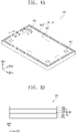
- FIG. 1A is a perspective view illustrating a display panel DP according to an embodiment of the invention.
- FIG. 1B is a sectional view illustrating the display panel DP according to an embodiment of the invention.
- the display panel DP shown in FIGS. 1A and 1B may be a light-emitting type display panel, and in an embodiment, the display panel DP may be one of an inorganic light emitting display panel or an organic light emitting display panel. However, the invention is not limited thereto.
- the display panel DP may include a display surface DP-IS, which is used to display an image.
- the display surface DP-IS may be parallel to a plane formed by a first direction axis DR1 and a second direction axis DR2.
- the display surface DP-IS may form a front surface of the display panel DP.
- a top surface of the topmost one of components constituting the display panel DP may be referred to as the display surface DP-IS.
- a top surface of an optical control layer OSL shown in FIG. 1B may be referred to as the display surface DP-IS of FIG. 1A .
- a normal direction of the display surface DP-IS e.g., a thickness direction of the display panel DP
- the third direction axis DR3 may be used to differentiate a front or top surface of each element (e.g., a layer or a unit) from a back or bottom surface.
- first to third directions DR1, DR2, and DR3 may be just an example.
- first to third directions may be referred to as directions that are indicated by the first to third direction axes DR1, DR2, and DR3, respectively, and will be identified with the same reference numbers.
- the display panel DP may include a display region DA and a non-display region NDA.
- a pixel PX may be disposed in the display region DA but not in the non-display region NDA.
- the non-display region NDA may be provided along an edge of the display surface DP-IS.
- the non-display region NDA may enclose the display region DA. In other words, the non-display region NDA may surround four sides of the display region DA.
- the non-display region NDA may be omitted or may be locally disposed near only one side portion of the display region DA.
- the display panel DP is illustrated to have a flat-type display surface DP-IS, but the invention is not limited to this example.
- the display panel DP may include a curved or three-dimensional display surface.
- the three-dimensional display surface may include a plurality of display regions, which are oriented in different directions.
- the display panel DP may be a rollable display panel, a foldable display panel, or a slidable display panel.
- the display panel DP may have a flexible property and may be provided as a folded or rolled component in a display device.
- the display panel DP may include a base substrate BS and a circuit element layer DP-CL, a display element layer DP-OLED, a first encapsulation layer TFE1, and the optical control layer OSL, which are disposed on the base substrate BS.
- the base substrate BS and the circuit element layer DP-CL, the display element layer DP-OLED, the first encapsulation layer TFE1, and the optical control layer OSL may be arranged in sequence.
- the base substrate BS may include a glass substrate, a plastic substrate, or a composite substrate made of organic and inorganic materials.
- the circuit element layer DP-CL may include a driving circuit of the pixel PX or a signal line.
- the display element layer DP-OLED may include an emission element disposed in each pixel PX.
- the first encapsulation layer TFE1 may include at least one inorganic layer, which is provided to hermetically seal or encapsulate the emission element.
- the optical control layer OSL may be configured to convert optical characteristics of a source light generated by the emission element.
- the display panel DP will be described in more detail with reference to FIGS. 2A and 2B .
- FIG. 2A is a sectional view taken along line I-I' of FIG. 1A .
- FIG. 2B is a sectional view taken along line II-II' of FIG. 1A .
- FIG. 2C is a sectional view illustrating a step of a process of fabricating the display panel DP.
- FIG. 2A illustrates a section corresponding to the pixel PX
- FIG. 2B illustrates a section corresponding to the non-display region NDA of the display panel DP.
- an emission element OLED is illustrated in a simplified manner.
- the display region DA may include a pixel region PXA and a peripheral region NPXA.
- the pixel region PXA may be disposed in each of a plurality of pixels PX shown in FIG. 1A .
- the peripheral region NPXA may delimit the plurality of pixel regions PXA and may prevent color-mixing from occurring in adjacent pixel regions PXA.
- the pixel region PXA may correspond to a second opening OP2, which will be described below.
- the peripheral region NPXA may be a region, in which a partition wall BW is disposed.
- the pixel regions PXA may include a first pixel region providing a first color light (e.g., red light), a second pixel region providing a second color light (e.g., green light), and a third pixel region providing a third color light (e.g., blue light).
- the red, green, and blue colors may be replaced by another set of primary colors, but the invention is not limited to this example.
- the description that follows will refer to an example in which the pixel region PXA of FIG. 2A is the first pixel region providing the red light.
- the first pixel region, the second pixel region, and the third pixel region may have substantially the same sectional structure, and thus, the first pixel region will be mainly described below. Differences between the first, second, and third pixel regions will be more clearly described below, and except for the differences, the first, second, and third pixel regions may be interpreted as having substantially the same structure.
- the first, second, and third pixel regions may have the same area or different areas and the invention is not limited to the areas of the first, second, and third pixel regions.
- the first, second, and third pixel regions may be arranged in a stripe shape or in a pentile shape, but the invention is not limited to this example.
- the first, second, and third pixel regions may be arranged in a specific rule.
- the minimum repetition unit of the first, second, and third pixel regions may be a unit pixel.
- the unit pixel may be a region, in which one first pixel region, one second pixel region, and one third pixel region are disposed.
- the unit pixel may include one first pixel region, two second pixel regions, and one third pixel region.
- the display panel DP may include a plurality of insulating layers, a plurality of semiconductor patterns, a plurality of conductive patterns, and a plurality of signal lines.
- an insulating layer, a semiconductor layer, and a conductive layer may be formed through a coating or deposition process. Thereafter, the insulating layer, the semiconductor layer, and the conductive layer may be selectively patterned by a photolithography and etching process. This method may be used to form the semiconductor patterns, the conductive patterns, and the signal lines constituting the circuit element layer DP-CL and the display element layer DP-OLED.
- the circuit element layer DP-CL may include a buffer layer BFL, a first insulating layer 10, a second insulating layer 20, and a third insulating layer 30.
- the buffer layer BFL, the first insulating layer 10, and the second insulating layer 20 may be inorganic layers, and the third insulating layer 30 may be an organic layer.
- FIG. 2A illustrates an example arrangement of an active A-D, a source S-D, a drain D-D, and a gate G-D constituting the driving transistor T-D.
- the active A-D, the source S-D, and the drain D-D may be portions of a semiconductor pattern that are distinguished according to their doping concentrations or conductivity types.
- the active A-D may be referred to as an active region
- the source S-D may be referred to as a source region or a source electrode
- the drain D-D may be referred to as a drain region or a drain electrode
- the gate G-D may be referred to as a gate electrode.
- the display element layer DP-OLED may include the emission element OLED.
- the emission element OLED may generate a source light.
- the emission element OLED may include a first electrode, a second electrode, and an emission layer therebetween.
- the display element layer DP-OLED may include an organic light emitting diode serving as its emission element.
- the display element layer DP-OLED may include a pixel definition layer PDL.
- the pixel definition layer PDL may be an organic layer.
- the pixel definition layer PDL may include a black coloring agent.
- the pixel definition layer PDL may include a base resin and a black dye or black pigment, which is mixed in the base resin.
- the black coloring agent may contain a carbon black or may include at least one of metallic materials (e.g., chromium) or oxides thereof.
- a first electrode AE of the emission element OLED may be disposed on the third insulating layer 30.
- the first electrode AE may be directly or indirectly connected to the driving transistor T-D.
- the first electrode AE may overlap the driving transistor T-D.
- a first opening OP1 may be provided in the pixel definition layer PDL. The first opening OP1 may expose at least a portion of the first electrode AE.
- a hole control layer HCL, an emission layer EML, an electron control layer ECL of the emission element OLED may be disposed in both of the pixel region PXA and the peripheral region NPXA.
- the hole control layer HCL, the emission layer EML, and the electron control layer ECL may be commonly disposed in a plurality of pixel regions PXAs.
- the emission layer EML in the pixel regions PXAs may be provided in the form of a single body.
- the emission layers in the first, second, and third pixel regions may be provided in the form of a single emission layer and may emit a source light of the same color, regardless of their regions.
- the hole control layer HCL may include a hole transport layer and, in an embodiment, the hole control layer HCL may further include a hole injection layer.
- the emission layer EML may generate a blue light as the source light.
- the blue light may have a wavelength ranging from 410nm to 480 nm.
- the blue light may have a light spectrum whose peak wavelength is within the range from 440 nm to 460 nm.
- the electron control layer ECL may include an electron transport layer, and in an embodiment, the electron control layer ECL may further include an electron injection layer.
- a second electrode CE may be disposed on the electron control layer ECL.
- the second electrode CE may be in direct contact with the electron control layer ECL.
- the second electrode CE may be commonly disposed in a plurality of pixel regions.
- the second electrode CE which is provided in the form of a single body, may be disposed in the plurality of pixel regions.
- the first encapsulation layer TFE1 may be disposed on the second electrode CE to hermetically seal or encapsulate the emission element OLED.
- the first encapsulation layer TFE1 may include at least one inorganic layer.
- the first encapsulation layer TFE1 may include a multi-layered structure, in which inorganic and organic layers are repeatedly stacked.
- the first encapsulation layer TFE1 may include a first encapsulation inorganic layer IOL1, an encapsulation organic layer OL, and a second encapsulation inorganic layer IOL2.
- the first and second encapsulation inorganic layer IOL1/IOL2 may protect the emission element OLED from external moisture, and the encapsulation organic layer OL may prevent an imprinting failure from occurring in the emission element OLED due to an external contaminant during the fabrication process.
- the display panel DP may further include a refractive index control layer, which is configured to improve the upward emission efficiency of the first encapsulation layer TFE1.
- the optical control layer OSL may be disposed on the first encapsulation layer TFE1.
- the optical control layer OSL may be disposed on the second encapsulation inorganic layer IOL2.
- the optical control layer OSL may include the partition wall BW, a light control pattern CCF-R, a second encapsulation layer TFE2, a color filter CF-R, and a protection layer OC.
- the partition wall BW may include a base resin having a highly transparent property and an additive agent.
- the base resin may be formed of various resin composites which may be called "binders".
- the additive agent may include a coupling agent and/or a photo-initiator.
- the additive agent may further include a dispersing agent.
- the partition wall BW may include a black coloring agent having a light blocking property.
- the partition wall BW may include a base resin and a black dye or black pigment mixed in the base resin.
- the black coloring agent may contain a carbon black or may contain at least one of metallic materials (e.g., chromium) or oxides thereof.
- the partition wall BW may include the second opening OP2 corresponding to the first opening OP1.
- the second opening OP2 may be overlapped with the first opening OP1 and may have an area larger than the first opening OP1.
- the second opening OP2 may be wider than the first opening OP1.
- the light control pattern CCF-R may be disposed in the second opening OP2.
- the light control pattern CCF-R may change optical characteristics of the source light.
- the light control pattern CCF-R may change optical characteristics of light emitted from the emission element OLED.
- the light control pattern CCF-R of the first and second pixel regions may be a color conversion pattern capable of changing the color of the source light. When the source light is a blue light, the color conversion pattern of the first pixel region may convert the source light to a red light, and the color conversion pattern of the second pixel region may convert the source light to a green light.
- the light control pattern CCF-R of the third pixel region may be a transmission pattern.
- the light control pattern CCF-R of the third pixel region may include scattering particles, and in this case, the source or blue light, which is incident into the third pixel region, may be scattered by the light control pattern CCF-R and may be emitted to the outside of the third pixel region.
- the color conversion pattern may include a base resin and quantum dots, which are mixed or dispersed in the base resin.
- the color conversion pattern may include a quantum dot, and in this sense, the color conversion pattern may be referred to as a quantum dot pattern.
- the color conversion patterns of the first and second pixel regions may include different quantum dots from each other.
- the base resin may be a medium material, in which the quantum dots are dispersed, and may be formed of at least one of various resin composites, which may be called "binders".
- the invention is not limited to this example, and in the present specification, if the quantum dots can be dispersed in a medium material, the medium material may be referred to as a base resin, regardless of its name, additional function, or constituents.
- the base resin may be a polymer resin.
- the base resin may be acrylic resins, urethane resins, silicone resins, and/or epoxy resins.
- the base resin may be transparent.
- the color conversion pattern may include a base resin and a scattering particle mixed in the base resin, like the transmission pattern.
- the scattering particle may be a nano particle that is formed of or includes titanium oxide (TiO 2 ) or silica.
- Quantum dots may be particles that cause a change in the wavelength of incident light.
- Each of the quantum dots may have a nanometer-order crystalline material consisting of hundreds to thousands of atoms and may exhibit an increase in band gap, due to its small size and the consequent quantum confinement effect.
- each of the quantum dots may absorb the light to enter an excited state, and then, may emit light of a specific wavelength to return to its ground state.
- the light emitted from the quantum dots may have an energy corresponding to the band gap.
- by adjusting sizes or compositions of the quantum dots it is possible to control the quantum confinement effect and the light-emitting characteristics of the optical conversion pattern.
- the quantum dot may be selected from the group consisting of II-VI compounds, I-III-VI compounds, III-V compounds, IV-VI compounds, IV elements, IV compounds, and combination thereof.
- the II-VI compounds may be selected from the group consisting of binary compounds (e.g., including CdSe, CdTe, CdS, ZnS, ZnSe, ZnTe, ZnO, HgS, HgSe, HgTe, MgSe, and MgS), mixtures of the binary compounds, ternary compounds (e.g., including AgInS, CdSeS, CdSeTe, CdSTe, ZnSeS, ZnSeTe, ZnSTe, HgSeS, HgSeTe, HgSTe, CdZnS, CdZnSe, CdZnTe, CdHgS, CdHgSe, CdHgTe, HgZnS, HgZnSe, HgZnTe, MgZnSe, and MgZnS), mixtures of the ternary compounds, quaternary compounds (e.g., including HgZn
- the I-III-VI compounds may be selected from the group consisting of ternary compounds (e.g., including AgInS2, CuInS2, AgGaS2, and CuGaS2), mixtures of the ternary compounds, quaternary compounds (e.g., including AgInGaS2 and CuInGaS2), and mixtures of the quaternary compounds.
- ternary compounds e.g., including AgInS2, CuInS2, AgGaS2, and CuGaS2
- quaternary compounds e.g., including AgInGaS2 and CuInGaS2
- mixtures of the quaternary compounds e.g., including AgInGaS2 and CuInGaS2
- the III-V compounds may be selected from the group consisting of binary compounds (e.g., including GaN, GaP, GaAs, GaSb, AlN, AlP, AlAs, AlSb, InN, InP, InAs, and InSb), mixtures of the binary compounds, ternary compounds (e.g., including GaNP, GaNAs, GaNSb, GaPAs, GaPSb, AlNP, AINAs, AINSb, AlPAs, AlPSb, InGaP, InAlP, InNP, InNAs, InNSb, InPAs, and InPSb), mixtures of the ternary compounds, quaternary compounds (e.g., including GaAlNP, GaAlNAs, GaAlNSb, GaAlPAs, GaAlPSb, GaInNP, GaInNAs, GaInNSb, GaInPAs, GaInPSb, InAlNP, InAlNAs, InAlNSb, InAlPAs, and InAlPS
- the IV-VI compounds may be selected from the group consisting of binary compounds (e.g., including SnS, SnSe, SnTe, PbS, PbSe, and PbTe), mixtures of the binary compounds, ternary compounds (e.g., including SnSeS, SnSeTe, SnSTe, PbSeS, PbSeTe, PbSTe, SnPbS, SnPbSe, and SnPbTe), mixtures of the ternary compounds, quaternary compounds (e.g., including SnPbSSe, SnPbSeTe, and SnPbSTe), and mixtures of the quaternary compounds.
- the IV elements may be selected from the group consisting of Si, Ge, and combination thereof.
- the IV compounds may include binary compounds selected from the group consisting of SiC, SiGe, and combination thereof.
- the binary, ternary, or quaternary compound may be provided to have a uniform concentration throughout the particle or to have a varying concentration distribution or spatially divided concentration states.
- the quantum dots may be a core-shell structure including a core and a shell enclosing the core.
- the quantum dots may have a core/shell structure, in which one quantum dot is enclosed by another quantum dot.
- an element contained in the shell may have a concentration gradient decreasing in a central direction.
- Each of the quantum dots may be a nanometer-scale particle.
- Each of the quantum dots may have a light-emitting wavelength spectrum whose full-width-at-half-maximum (FWHM) is less than about 45 nm (in particular, less than about 40 nm or in more particular, less than about 30 nm), and in this case, it is possible to improve color purity or color reproduction characteristics. Furthermore, since the quantum dots emit light radially, it is possible to improve a viewing angle property.
- FWHM full-width-at-half-maximum
- the quantum dots may be a spherical, pyramid-shaped, multi-arm, or cubic nano particle.
- the quantum dots may be a nano tube, a nano wire, a nano fiber, a nano plate-shaped particle, but the shape of the quantum dots is not limited to these examples.
- a wavelength or color of light emitted from the quantum dot may be determined by a particle size of the quantum dot, and thus, in the case where the quantum dots are provided in various sizes, lights converted by the quantum dots may have various colors (e.g., red, green, and blue).
- the light control pattern CCF-R may be formed by an inkjet process.
- a liquid composite may be provided in the second opening OP2.
- a composite material, which is polymerized by a thermal curing process or optical curing process, may have a reduced volume after the curing process.
- top surface of the partition wall BW may be higher than the top surface of the light control pattern CCF-R.
- the difference in height between the top surface of the partition wall BW and the top surface of the light control pattern CCF-R may range from about 2 ⁇ m to about 3 ⁇ m.
- the second encapsulation layer TFE2 may be disposed on the partition wall BW to be overlapped with the light control pattern CCF-R.
- the second encapsulation layer TFE2 may include a first encapsulation inorganic layer IOL10, an encapsulation organic layer OL-1, and a second encapsulation inorganic layer IOL20.
- Each of the first encapsulation inorganic layer IOL10, the encapsulation organic layer OL-1, and the second encapsulation inorganic layer IOL20 may be provided in the second opening OP2.
- the first and second encapsulation inorganic layers IOL10 and IOL20 may protect the light control pattern CCF-R from external moisture, and the encapsulation organic layer OL-1 may remove an uneven profile that is formed by a difference in height between the partition wall BW and the light control pattern CCF-R and may provide a flat base surface to an element to be disposed thereon.
- Each of the first and second encapsulation inorganic layers IOL10 and IOL20 may be formed of or include at least one of silicon oxide, silicon oxynitride, or silicon nitride.
- the encapsulation organic layer OL-1 may be formed of or include an organic material (e.g., acrylic organic materials).
- the color filter CF-R may be disposed on the second encapsulation layer TFE2.
- the color filter CF-R may be transparent to light in a specific wavelength range and may block light whose wavelength is not within the wavelength range.
- the color filter CF-R of the first pixel region may be transparent to a red light that passes therethrough and may block green and blue lights.
- the color filter CF-R may include a base resin and a dye and/or pigment dispersed in the base resin.
- the base resin may be a medium material, in which the dye and/or pigment is dispersed, and may be made of at least one of various resin composites, which may be called "binders".
- the color filter CF-R may be formed on a flat surface and may have a uniform thickness in the pixel region PXA. A red light generated in the light control pattern CCF-R may be emitted to the outside of the pixel region PXA with a uniform brightness.
- the protection layer OC may be disposed on the color filter CF-R.
- the protection layer OC may be an organic layer which is used to protect the color filter CF-R.
- the protection layer OC may be formed of or include an optically- or thermally-curable organic material.
- a glass substrate may be further disposed on the protection layer OC.
- the glass substrate may protect the underlying layers of the display panel DP.
- An adhesive layer may be disposed between the protection layer OC and the glass substrate.
- the protection layer OC may be formed of or include an inorganic material.
- the display panel DP may include a dam line DM, which is disposed outside the pixel definition layer PDL and is overlapped with the non-display region NDA.
- FIG. 2B illustrates an example, in which two dam lines DM are provided, but the invention is not limited to the specific number of the dam lines DM.
- the dam line DM may be omitted.
- the dam line DM may delimit a region, which is occupied by a liquid composite during a process of fabricating the encapsulation organic layer OL of the first encapsulation layer TFE1, within the border of the base substrate BS.
- a position of an edge of the encapsulation organic layer OL of the first encapsulation layer TFE1 may be limited to a region inside the dam line DM, e.g., in the right portion of FIG. 2B .
- the encapsulation organic layer OL of the first encapsulation layer TFE1 may end at the dam line DM.
- the dam line DM may include a first layer D-1 and a second layer D-2, which is disposed on the first layer D-1.
- the first layer D-1 may be formed by the same fabrication process (including a photolithography step and a developing step) as the third insulating layer 30, and the second layer D-2 may be formed by the same fabrication process (including a photolithography step and a developing step) as the pixel definition layer PDL.
- a sub-dam line DM-S may be further provided outside the dam line DM (e.g., in the left portion of FIG. 2B ).
- the first and second encapsulation inorganic layers IOL1 and IOL2 of the first encapsulation layer TFE1 may be overlapped with the dam line DM.
- the first and second encapsulation inorganic layers IOL1 and IOL2 of the first encapsulation layer TFE1 may be disposed inside the sub-dam line DM-S. In other words, the first and second encapsulation inorganic layers IOL1 and IOL2 of the first encapsulation layer TFE1 may not extend beyond the sub-dam line DM-S.
- the partition wall BW may also be overlapped with the peripheral region NPXA and the non-display region NDA.
- the partition wall BW may be overlapped with the dam line DM and the sub-dam line DM-S.
- a dummy opening OP-D which is overlapped with the non-display region NDA, may be provided in the partition wall BW.
- FIG. 2B illustrates an example in which two dummy openings OP-D are disposed at the left side of the outermost one of the second openings OP2 in the display region DA.
- a dummy control pattern CCF-D may be disposed in the dummy opening OP-D. Since the dummy control pattern CCF-D fills the dummy opening OP-D, a difference in height between the partition wall BW and a region corresponding to the dummy opening OP-D may be reduced. A difference in height between the partition wall BW and the dummy control pattern CCF-D may be controlled to have substantially the same value as that between the partition wall BW and the light control pattern CCF-R. In other words, the top of the dummy control pattern CCF-D may be lower than a top of the partition wall BW.
- the dummy control pattern CCF-D may be formed by the same process as that for the light control pattern CCF-R and, in this case, it may be formed of the same material as the light control pattern CCF-R.
- the second encapsulation layer TFE2 may not be normally formed in the dummy opening OP-D.
- the photosensitive organic material may be insufficiently cured, and in this case, a failure, such as an out-gassing phenomenon, may occur.
- the dummy control pattern CCF-D may be disposed in the dummy opening OP-D.
- the dummy opening OP-D may be overlapped with the pixel definition layer PDL. In this case, it is possible to control a depth of the dummy opening OP-D to a value similar to the depth of the second opening OP2. If the dummy opening OP-D is not overlapped with the pixel definition layer PDL, the dummy opening OP-D may be formed to have a depth that is larger than a reference value, and in this case, a difference in height between the dummy control pattern CCF-D and the partition wall BW may not be controlled.
- the partition wall BW and the dummy control pattern CCF-D may be formed to have a height difference that is larger than that between the partition wall BW and the light control pattern CCF-R. In this case, the partition wall BW and the dummy control pattern CCF-D may be formed to have a height difference larger than the reference value. In such a case, the afore-stated failure may be likely to occur.
- the first encapsulation inorganic layer IOL10 of second encapsulation layer TFE2 may be disposed on the partition wall BW, the light control pattern CCF-R, and the dummy control pattern CCF-D.
- the difference in height between the underlying patterns may be transcribed to the first encapsulation inorganic layer IOL10. This is because the first encapsulation inorganic layer IOL10 is formed by a deposition process.
- a first step which is substantially the same as a step formed by the partition wall BW and the light control pattern CCF-R and a second step, which is substantially the same as a step formed by the partition wall BW and the dummy control pattern CCF-D, may be formed on a top surface of the first encapsulation inorganic layer IOL10.
- the first and second steps may be adjacent to each other.
- An edge of the encapsulation organic layer OL-1 of the second encapsulation layer TFE2 may be overlapped with the dummy opening OP-D (e.g., the dummy control pattern CCF-D). Due to the step formed by the partition wall BW and the dummy control pattern CCF-D, when a liquid composite OL-P is used in a process of forming the encapsulation organic layer OL-1, it is possible to delimit a region occupied by the liquid composite OL-P or thereby to prevent the encapsulation organic layer OL-1 from being formed in a region beyond the base substrate BS.
- FIG. 2C illustrates a profile of the liquid composite OL-P, which may be outwardly overflowed when the dummy opening OP-D is omitted. For example, if the dummy opening OP-D is omitted, the liquid composite OL-P may overflow to an area beyond the leftmost dummy opening OP-D in FIG. 2C .
- the dummy opening OP-D and the dummy control pattern CCF-D may serve as a stopper for stopping the liquid composite OL-P from outwardly flowing. Since the structure serving as the stopper is formed without an additional process, it is possible to realize a highly reliable display panel without an increase in fabrication cost.
- the liquid composite OL-P forming the encapsulation organic layer OL-1 of the second encapsulation layer TFE2 may end at the dummy opening OP-D.
- the encapsulation organic layer OL-1 may extend from the display region DA to the dummy opening OP-D closest to the dam line DM in the non-display region NDA.
- the encapsulation organic layer OL-1 may end at the dummy opening OP-D closest to the second opening OP2.
- the right curved dash line in FIG. 2C illustrates a profile of the liquid composite OL-P in which the outward flow of the liquid composite OL-P is stopped by a step formed by the partition wall BW and the outermost light control pattern CCF-R, when the dummy opening OP-D is omitted.
- the color filter CF-R which is overlapped with the outermost one of the second openings OP2, may not have a uniform thickness.
- a small amount of the liquid composite OL-P is provided to prevent defects such as the left dash line of FIG. 2C . But this may cause another defect such as the right dash line of FIG. 2C .
- the first encapsulation inorganic layer IOL10 of the second encapsulation layer TFE2 is illustrated to have a single-layered structure, the first encapsulation inorganic layer IOL10 may have a multi-layered structure.
- the first encapsulation inorganic layer IOL10 may include a silicon oxynitride layer and a silicon oxide layer thereon.
- a silicon oxynitride layer which has high moisture-prevention efficiency, may be used to directly cover the light control pattern CCF-R.
- a silicon oxynitride layer which is formed by a low temperature deposition process, may have a layer density higher than a silicon oxide layer and may exhibit a high coupling strength to an underlying layer.
- the liquid composite OL-P may be provided onto a center region of the display region DA (e.g., see FIG. 1A ) in the form of droplet, and in this case, it may be necessary to supply the liquid composite OL-P to the non-display region NDA.
- the liquid composite OL-P may flow smoothly toward the non-display region NDA while filling the uneven region, which is formed by a difference in height between the second opening OP2 and the light control pattern CCF-R.
- the first encapsulation inorganic layer IOL10 may include a silicon oxide layer. Since the silicon oxide layer is relatively hydrophilic compared with silicon oxynitride layer, the silicon oxide layer may improve the fluidity of the liquid composite OL-P.
- the second encapsulation inorganic layer IOL20 of the second encapsulation layer TFE2 may be disposed on a top surface BW-US of the partition wall BW to be in contact with the first encapsulation inorganic layer IOL10 of the second encapsulation layer TFE2.
- the first and second encapsulation inorganic layers IOL10 and IOL20 may be in direct contact with each other.
- the second encapsulation inorganic layer IOL20 may hermetically seal the encapsulation organic layer OL-1 thereunder, and thus, the light control pattern CCF-R may be further hermetically sealed by the second encapsulation inorganic layer IOL20.
- At least one of the first and second encapsulation inorganic layers IOL10 and IOL20 may be disposed on a side surface BW-SS of the partition wall BW. Such an encapsulation inorganic layer may hermetically seal the partition wall BW.
- At least one of the first and second encapsulation inorganic layers IOL10 and IOL20 may be in contact with an inorganic layer of the circuit element layer DP-CL.
- the partition wall BW may be hermetically sealed by the inorganic layers (e.g., the second insulating layer 20 and one of the encapsulation inorganic layers IOL10 and IOL20). In this case, it is possible to prevent the partition wall BW from being damaged by a wet process of forming the color filter CF-R and the protection layer OC.
- two or more color filters CF-R and CF-B in the non-display region NDA may be disposed on the second encapsulation layer TFE2.
- the two color filters CF-R and CF-B stacked may serve as a light-blocking pattern.
- an embodiment of the invention provides a display panel DP including: a display region DA including pixels PX and a non-display region NDA adjacent to the display region DA, wherein each pixel PX includes an emission element OLED, each of the emission elements including a first electrode AE, an emission layer EML disposed on the first electrode AE, and a second electrode CE disposed on the emission layer EML; a pixel definition layer PDL including a first opening OP1 that exposes the first electrode AE of each of the emission elements OLED; a first encapsulation layer TFE1 disposed on the pixel definition layer PDL and overlapping the emission elements OLED; a partition wall BW disposed on the first encapsulation layer TFE1 and including a second opening OP2 corresponding to the first opening OP1 and a dummy opening OP-D overlapping the non-display region NDA; a light control pattern CCF-R disposed in the second opening OP2
- FIG. 3A is a plan view illustrating the display panel DP according to an embodiment of the invention.
- FIG. 3B is a plan view illustrating the display panel DP according to an embodiment of the invention.
- FIG. 4A is a plan view illustrating the display panel DP according to an embodiment of the invention.
- FIG. 4B is a plan view illustrating the display panel DP according to an embodiment of the invention.
- an element previously described with reference to FIGS. 1A to 2B may be identified by the same reference number without repeating an overlapping description thereof.
- the pixel definition layer PDL may be overlapped with the display region DA and may be partially overlapped with the non-display region NDA, when viewed in a plan view.
- An edge of the pixel definition layer PDL may be disposed outside the display region DA.
- the first opening OP1 may be disposed in each of the pixels PX shown in FIG. 1A .
- FIG. 3A illustrates an example, in which one dam line DM is provided to be spaced apart from the edge of the pixel definition layer PDL.
- the dam line DM may have a closed-line shape, when viewed in a plan view.
- the dam line DM may be located between an edge of the pixel definition layer PDL and an edge of the base substrate BS.
- the partition wall BW may be overlapped with the display region DA and may be partially overlapped with the non-display region NDA, when viewed in a plan view.
- An edge of the partition wall BW may be disposed outside the edge of the pixel definition layer PDL shown in FIG. 3A .
- the second opening OP2 may be disposed in each of the first openings OP1 of FIG. 3A .
- the dummy opening OP-D may have the same area as the second opening OP2, when viewed in a plan view.
- the dummy opening OP-D may be formed under the same condition as that for the second opening OP2.
- the dummy opening OP-D and the second opening OP2 may be formed through the same process without any additional mask.
- FIG. 3B illustrates an example in which the dummy openings OP-D are arranged outside the display region DA to form a single group enclosing the display region DA.
- the dummy openings OP-D may be arranged to form a pair of groups, each of which encloses the display region DA.
- the dummy openings OP-D may be formed on less than all sides of the display region DA.
- the dummy opening OP-D may be different from the second opening OP2 in terms of area and shape, when viewed in a plan view.
- the dummy opening OP-D may have a closed-line shape continuously enclosing the display region DA.
- the dummy opening OP-D may include four regions that are provided to face four different edges of the display region DA. In this case, spaces may be provided between adjacent ones of the four regions of the dummy opening OP-D.
- a second encapsulation layer may be disposed to hermetically seal or encapsulate a partition wall, and in this case, it is possible to reduce a delamination or loosing failure in the partition wall.
- a light-blocking structure may be formed using a color filter.
Landscapes
- Physics & Mathematics (AREA)
- Optics & Photonics (AREA)
- Engineering & Computer Science (AREA)
- Microelectronics & Electronic Packaging (AREA)
- Chemical & Material Sciences (AREA)
- Crystallography & Structural Chemistry (AREA)
- Inorganic Chemistry (AREA)
- Nanotechnology (AREA)
- Electroluminescent Light Sources (AREA)
Applications Claiming Priority (1)
| Application Number | Priority Date | Filing Date | Title |
|---|---|---|---|
| KR1020210046747A KR20220140935A (ko) | 2021-04-09 | 2021-04-09 | 표시패널 |
Publications (1)
| Publication Number | Publication Date |
|---|---|
| EP4071824A1 true EP4071824A1 (fr) | 2022-10-12 |
Family
ID=81306777
Family Applications (1)
| Application Number | Title | Priority Date | Filing Date |
|---|---|---|---|
| EP22167379.1A Pending EP4071824A1 (fr) | 2021-04-09 | 2022-04-08 | Panneau d'affichage |
Country Status (4)
| Country | Link |
|---|---|
| US (1) | US20220328581A1 (fr) |
| EP (1) | EP4071824A1 (fr) |
| KR (1) | KR20220140935A (fr) |
| CN (2) | CN218831232U (fr) |
Cited By (1)
| Publication number | Priority date | Publication date | Assignee | Title |
|---|---|---|---|---|
| EP4236657A1 (fr) * | 2022-02-25 | 2023-08-30 | Samsung Display Co., Ltd. | Dispositif d'affichage |
Citations (4)
| Publication number | Priority date | Publication date | Assignee | Title |
|---|---|---|---|---|
| US20180182816A1 (en) * | 2016-12-26 | 2018-06-28 | Lg Display Co., Ltd. | Display Device with Integrated Touch Screen |
| US20200258944A1 (en) * | 2019-02-11 | 2020-08-13 | Samsung Display Co. Ltd. | Display device |
| EP3706184A1 (fr) * | 2019-03-05 | 2020-09-09 | Samsung Display Co., Ltd. | Panneau d'affichage |
| EP4002473A1 (fr) * | 2020-11-13 | 2022-05-25 | Samsung Display Co., Ltd. | Dispositif d'affichage |
-
2021
- 2021-04-09 KR KR1020210046747A patent/KR20220140935A/ko active Search and Examination
-
2022
- 2022-01-13 US US17/574,729 patent/US20220328581A1/en active Pending
- 2022-04-08 EP EP22167379.1A patent/EP4071824A1/fr active Pending
- 2022-04-11 CN CN202220819919.3U patent/CN218831232U/zh active Active
- 2022-04-11 CN CN202210372845.8A patent/CN115207045A/zh active Pending
Patent Citations (4)
| Publication number | Priority date | Publication date | Assignee | Title |
|---|---|---|---|---|
| US20180182816A1 (en) * | 2016-12-26 | 2018-06-28 | Lg Display Co., Ltd. | Display Device with Integrated Touch Screen |
| US20200258944A1 (en) * | 2019-02-11 | 2020-08-13 | Samsung Display Co. Ltd. | Display device |
| EP3706184A1 (fr) * | 2019-03-05 | 2020-09-09 | Samsung Display Co., Ltd. | Panneau d'affichage |
| EP4002473A1 (fr) * | 2020-11-13 | 2022-05-25 | Samsung Display Co., Ltd. | Dispositif d'affichage |
Cited By (1)
| Publication number | Priority date | Publication date | Assignee | Title |
|---|---|---|---|---|
| EP4236657A1 (fr) * | 2022-02-25 | 2023-08-30 | Samsung Display Co., Ltd. | Dispositif d'affichage |
Also Published As
| Publication number | Publication date |
|---|---|
| US20220328581A1 (en) | 2022-10-13 |
| CN115207045A (zh) | 2022-10-18 |
| CN218831232U (zh) | 2023-04-07 |
| KR20220140935A (ko) | 2022-10-19 |
Similar Documents
| Publication | Publication Date | Title |
|---|---|---|
| US11204518B2 (en) | Display panel and manufacturing method thereof | |
| US11469287B2 (en) | Display panel and method for manufacturing the same | |
| US11889718B2 (en) | Display panel including functional layer | |
| US20230006184A1 (en) | Display panel | |
| US20230413636A1 (en) | Display panel and manufacturing method therefor | |
| EP3893284A1 (fr) | Panneau d'affichage | |
| EP4071824A1 (fr) | Panneau d'affichage | |
| EP4175446A1 (fr) | Panneau d'affichage | |
| US20210376000A1 (en) | Display panel and method for manufacturing the same | |
| US11696463B2 (en) | Display panel and method of manufacturing the same | |
| US11569305B2 (en) | Display panel including reflection pattern | |
| US20230169914A1 (en) | Display panel and fabricating method of the same | |
| CN220383485U (zh) | 显示装置 | |
| CN221081904U (zh) | 显示装置 | |
| US20230074534A1 (en) | Display device and method for manufacturing the same | |
| US20230068622A1 (en) | Display panel and manufacturing method of the same | |
| US20230157120A1 (en) | Display device | |
| CN219205142U (zh) | 显示装置 | |
| US20220293685A1 (en) | Display panel and manufacturing method thereof | |
| US20230131912A1 (en) | Display panel and method for manufacturing the same | |
| CN116423995A (zh) | 喷墨打印装置和使用该装置制造显示装置的方法 | |
| KR20220131401A (ko) | 표시 장치 |
Legal Events
| Date | Code | Title | Description |
|---|---|---|---|
| PUAI | Public reference made under article 153(3) epc to a published international application that has entered the european phase |
Free format text: ORIGINAL CODE: 0009012 |
|
| STAA | Information on the status of an ep patent application or granted ep patent |
Free format text: STATUS: THE APPLICATION HAS BEEN PUBLISHED |
|
| AK | Designated contracting states |
Kind code of ref document: A1 Designated state(s): AL AT BE BG CH CY CZ DE DK EE ES FI FR GB GR HR HU IE IS IT LI LT LU LV MC MK MT NL NO PL PT RO RS SE SI SK SM TR |
|
| STAA | Information on the status of an ep patent application or granted ep patent |
Free format text: STATUS: REQUEST FOR EXAMINATION WAS MADE |
|
| 17P | Request for examination filed |
Effective date: 20230329 |
|
| RBV | Designated contracting states (corrected) |
Designated state(s): AL AT BE BG CH CY CZ DE DK EE ES FI FR GB GR HR HU IE IS IT LI LT LU LV MC MK MT NL NO PL PT RO RS SE SI SK SM TR |
|
| P01 | Opt-out of the competence of the unified patent court (upc) registered |
Effective date: 20230516 |