EP4071015B1 - Pneumatischer federbremszylinder - Google Patents
Pneumatischer federbremszylinder Download PDFInfo
- Publication number
- EP4071015B1 EP4071015B1 EP21167297.7A EP21167297A EP4071015B1 EP 4071015 B1 EP4071015 B1 EP 4071015B1 EP 21167297 A EP21167297 A EP 21167297A EP 4071015 B1 EP4071015 B1 EP 4071015B1
- Authority
- EP
- European Patent Office
- Prior art keywords
- spring brake
- piston
- spring
- actuator
- section
- Prior art date
- Legal status (The legal status is an assumption and is not a legal conclusion. Google has not performed a legal analysis and makes no representation as to the accuracy of the status listed.)
- Active
Links
Images


Classifications
-
- B—PERFORMING OPERATIONS; TRANSPORTING
- B60—VEHICLES IN GENERAL
- B60T—VEHICLE BRAKE CONTROL SYSTEMS OR PARTS THEREOF; BRAKE CONTROL SYSTEMS OR PARTS THEREOF, IN GENERAL; ARRANGEMENT OF BRAKING ELEMENTS ON VEHICLES IN GENERAL; PORTABLE DEVICES FOR PREVENTING UNWANTED MOVEMENT OF VEHICLES; VEHICLE MODIFICATIONS TO FACILITATE COOLING OF BRAKES
- B60T17/00—Component parts, details, or accessories of power brake systems not covered by groups B60T8/00, B60T13/00 or B60T15/00, or presenting other characteristic features
- B60T17/08—Brake cylinders other than ultimate actuators
- B60T17/083—Combination of service brake actuators with spring loaded brake actuators
-
- F—MECHANICAL ENGINEERING; LIGHTING; HEATING; WEAPONS; BLASTING
- F16—ENGINEERING ELEMENTS AND UNITS; GENERAL MEASURES FOR PRODUCING AND MAINTAINING EFFECTIVE FUNCTIONING OF MACHINES OR INSTALLATIONS; THERMAL INSULATION IN GENERAL
- F16D—COUPLINGS FOR TRANSMITTING ROTATION; CLUTCHES; BRAKES
- F16D65/00—Parts or details
- F16D65/14—Actuating mechanisms for brakes; Means for initiating operation at a predetermined position
- F16D65/28—Actuating mechanisms for brakes; Means for initiating operation at a predetermined position arranged apart from the brake
-
- F—MECHANICAL ENGINEERING; LIGHTING; HEATING; WEAPONS; BLASTING
- F16—ENGINEERING ELEMENTS AND UNITS; GENERAL MEASURES FOR PRODUCING AND MAINTAINING EFFECTIVE FUNCTIONING OF MACHINES OR INSTALLATIONS; THERMAL INSULATION IN GENERAL
- F16D—COUPLINGS FOR TRANSMITTING ROTATION; CLUTCHES; BRAKES
- F16D2121/00—Type of actuator operation force
- F16D2121/02—Fluid pressure
- F16D2121/08—Fluid pressure acting on a membrane-type actuator, e.g. for gas pressure
- F16D2121/10—Fluid pressure acting on a membrane-type actuator, e.g. for gas pressure for releasing a normally applied brake
-
- F—MECHANICAL ENGINEERING; LIGHTING; HEATING; WEAPONS; BLASTING
- F16—ENGINEERING ELEMENTS AND UNITS; GENERAL MEASURES FOR PRODUCING AND MAINTAINING EFFECTIVE FUNCTIONING OF MACHINES OR INSTALLATIONS; THERMAL INSULATION IN GENERAL
- F16D—COUPLINGS FOR TRANSMITTING ROTATION; CLUTCHES; BRAKES
- F16D2125/00—Components of actuators
- F16D2125/02—Fluid-pressure mechanisms
- F16D2125/10—Plural pistons interacting by fluid pressure, e.g. hydraulic force amplifiers using different sized pistons
Definitions
- the invention relates to a pneumatic spring brake actuator, in particular a parking and service brake actuator for use in a commercial vehicle, said actuator comprising a housing comprising a housing base, a spring brake piston accommodated at least partially in said housing said spring brake piston being configured to reciprocatingly move between a retained position and an extended position along a longitudinal axis as a function of pressure inside a spring brake pressure chamber, and a compression spring located between the housing and the spring brake piston, said compression spring being effective to push the spring brake piston towards the extended position.
- Pneumatic spring brake actuators of the aforementioned kind are commonly used in the commercial vehicle industry. It is the aim of such pneumatic service brake actuators to generate a braking force which is, in turn, transmitted to the vehicle wheel.
- pneumatic spring brake actuators comprise two units that are arranged behind one another along a longitudinal axis of said actuator: a spring brake part and a service brake part.
- the spring brake part provides an emergency braking functionality and the service brake part a service brake functionality.
- the two components are connected together and often act upon the same brake components which transmit the brake force to the vehicle wheel.
- US 2010/0320039 A1 and US 6,435,321 B1 shows a brake cylinder for vehicles wherein the brake cylinder is compact and simple to construct.
- US 2007/0246313 A1 refers also to a short brake cylinder for motor vehicles.
- the spring loaded piston and the pressurized piston connected each other through a shift cylinder.
- US 2007/0214953 A1 refers to a combined service brake and spring brake cylinder wherein the brake piston configured to reciprocatingly move between a retained position and an extended position.
- the spring brake piston comprises a service brake pressure chamber, a piston chamber, and a service brake piston separating the service brake pressure chamber from the piston chamber, wherein said service brake piston is configured to reciprocratingly move between a retained position and an extended position along said longitudinal axis as a function of pressure inside the service brake pressure chamber.
- the invention is based upon the finding that by integrating said service brake pressure chamber, piston chamber and piston into said spring brake piston, the overall length of said actuator can be reduced significantly.
- the proposed design no longer proposed to arrange spring brake part and service brake part behind one another, but integrated with regard to one another.
- said service brake pressure chamber is arranged coaxially, with regard said longitudinal axis, around said spring brake pressure chamber. This coaxial design helps to reduce the overall length of the actuator.
- said spring brake piston comprises a front face, said front face being arranged opposite from said housing base, and a first pipe section extending from said front face towards said housing base, wherein said first pipe section radially limits said service brake pressure chamber and piston chamber. With the help of such first pipe section, the service brake pressure chamber and the piston chamber are at least partially established within said spring brake piston.
- said spring brake piston comprises a second pipe section extending coaxially around said first pipe section, wherein said second pipe section comprises a radial protrusion abutting against a radial wall of said housing, wherein a volume between said second pipe section, said protrusion and said radial wall defines said spring brake pressure chamber.
- said compression spring is arranged between said first pipe section and said second pipe section.
- said protrusion comprises a seal configured to seal said protrusion against said radial housing wall.
- seal may be a radial shaft seal, for example. With the help of such seal, said spring brake pressure chamber may be sealed appropriately.
- said actuator comprises a guide sleeve being connected to said housing base, wherein said guide sleeve is configured for radially guiding said spring brake piston.
- a seal is provided between said guide sleeve and said spring brake piston.
- said guide sleeve comprises a sleeve section for radially guiding said first pipe section of said spring brake piston and a flange section arranged adjacent to said sleeve section, wherein said flange section extends radially from said sleeve section.
- the guide sleeve may be mounted durably to said housing base.
- said flange section is connected to said housing base by means of a screw joint.
- Said screw joint preferably comprises screws arranged on a circle around the longitudinal axis at said housing base.
- said actuator comprises a piston spring arranged inside said piston chamber, said piston spring being effective to push the spring brake piston towards said retained position.
- said housing comprises a housing flange section extending radially outwards from said radial housing wall, and a cover section abutting against said flange section, wherein said cover section comprises an opening configured for accommodating said second pipe section of said spring brake piston.
- the actuator can be conveniently mounted wherein said spring brake piston is enabled to be moved into said extended position.
- said cover section comprises a spring brake port for providing pressurized fluid to said spring brake pressure chamber.
- Said port preferably extends radially outwards from said cover section. In this way, the dimensions of said actuator with regard to its length can be further reduced, since no additional volume in the length direction is required for said spring brake port.
- said spring piston chamber comprises a step for limiting a movement of said service brake piston towards said extending position.
- said housing base comprises a service brake port for providing pressurized fluid to said service brake pressure chamber, wherein said service brake port is centered along said longitudinal axis. With the help of said service brake port, pressurized fluid can be provided to said service brake, in particular said service brake pressure chamber.
- said actuator comprises a brake release mechanism configured for releasing said spring brake piston against said compression spring. It is the aim of said release mechanisms to release said spring brake piston, for example in case of pneumatic system malfunctions.
- said service brake port is configured for accommodating said release mechanism at least partially.
- said service brake port has to two functions. On the one hand, the port is utilized to provide pressurized fluid to said service brake and on the other hand, said port is utilized for inserting the brake release mechanism into the actuator.
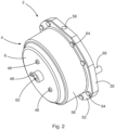
- Fig. 1 shows a pneumatic spring brake actuator 2.
- the spring brake actuator 2 is a parking and service brake actuator 2 for use in a commercial vehicle (not shown).
- the spring brake actuator 2 comprises a housing 4.
- the housing 4 comprises a housing base 6.
- the spring brake actuator 2 comprises a spring brake piston 8.
- the spring brake piston 8 is at least partially accommodated in the housing 4.
- the spring brake piston 8 is configured to reciprocratingly move between a retained position 10 and an extended position (not shown) along a longitudinal axis 14.
- the spring brake actuator 2 furthermore comprises a spring brake pressure chamber 16.
- the spring brake piston 8 moves between the retained position 10 and the extended position (not shown) as a function of pressure inside the spring brake pressure chamber 16.
- a compression spring 18 is located between the housing 4 and the spring brake piston 8.
- the compression spring 18 is effective to push the spring brake piston 8 towards the extended position (not shown).
- the spring brake piston 8 furthermore comprises a service brake pressure chamber 20.
- the spring brake piston 8 furthermore comprises a piston chamber 22.
- the spring brake piston 8 moreover comprises a service brake piston 24.
- the service brake piston 24 separates the service brake pressure chamber 20 from the piston chamber 22.
- the service brake piston 22 is configured to reciprocatingly move between a retained position 26 and an extend position 28 along the longitudinal axis 14 as a function of pressure inside the service brake pressure chamber 20.
- the service brake pressure chamber 20 is arranged coaxially, with regard to said longitudinal axis 14, around the spring brake pressure chamber 16.
- the spring brake piston 8 comprises a front face 30.
- the front face 30 is arranged opposite the housing base 6.
- the spring brake piston 8 comprises a first pipe section 32.
- the first pipe section extends from the front face 30 towards the housing base 6.
- the first pipe section 32 radially limits the service brake pressure chamber 20 and the piston chamber 22.
- the spring brake piston 8 comprises a second pipe section 34.
- the second pipe section 34 extends coaxially around the first pipe section 32.
- the second pipe section 34 comprises a radial protrusion 36.
- the radial protrusion 36 abuts against a radial wall 38 of said housing 4.
- a volume between the second pipe section 34, the protrusion 36 and the radial wall 38 defines the spring brake pressure chamber 16.
- the compression spring 18 is arranged between the first pipe section 32 and the second pipe section 34.
- the protrusion 36 comprises a seal 40.
- the seal 40 is configured to seal the protrusion 36 against the radial housing wall 38.
- the actuator 2 furthermore comprises a guide sleeve 42.
- the guide sleeve 42 is connected to the housing base 6.
- the guide sleeve 42 is configured for radially guiding said spring brake piston 8.
- the guide sleeve 42 comprises a sleeve section 44.
- the sleeve section 44 radially guides said first pipe section 32 of said spring brake piston 8.
- the guide sleeve 42 furthermore comprises a flange section 46.
- the flange section 46 is arranged adjacent to said sleeve section 44.
- the flange section 46 extends radially from the sleeve section 44.
- the flange section 46 is connected to the housing base 6 by means of screw joints 48.
- the actuator 2 comprises a piston spring 50.
- the piston spring 50 is arranged inside the piston chamber 22.
- the piston spring 50 is effective to push the spring brake piston 8 towards the retained position 26.
- the housing 4 comprises a housing flange section 52.
- the housing flange section 52 extends radially outwards from the radial housing wall 38.
- the housing 4 furthermore comprises a cover section 54.
- the cover section 54 abuts against the flange section 46.
- the cover section 54 comprises an opening 56.
- the opening 56 is configured for accommodating the second pipe section 34 of the spring brake 4 of the spring brake piston 8.
- the cover section 54 comprises a spring brake port 58.
- the spring brake port 58 is configured for providing pressurized fluid to the spring brake pressure chamber 16.
- the spring brake port 58 extends radially outwards from said cover section 54.
- the piston chamber 22 comprises a step 60.
- the step 60 limits a movement of service brake piston 24 towards the extended position.
- the housing base 6 comprises a service brake port 62.
- the service brake port 62 provides pressurized fluid to the service brake pressure chamber 20.
- the service brake port 62 is centered along the longitudinal axis 14.
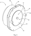
- the spring brake actuator 2 comprises the housing 4 having the housing base 6.
- the housing base 6 comprises the service brake port 62, wherein the service brake port 62 is centered along the longitudinal axis 14.
- the housing 4 furthermore comprises the radial housing wall 38 and the housing flange section 52 extending radially outwards from the radial housing wall 38.
- the cover section 54 abuts against the flange section 46.
- the cover section 54 is connected to the housing flange section 52 by means of screws 64.
- the spring brake port 58 extends radially outwards from the cover section 54.
- Fig. 2 furthermore shows the screw joint 48 connecting the flange section 46 (see fig. 1 ) to the housing base 6.
- the housing 4 furthermore comprises alignment bolts 66 connected to the cover section 54.
- Fig. 3 shows the spring brake actuator 2 in a rotated perspective, compared to fig. 2 .
- fig. 3 shows the two alignment bolts 66 being connected to the cover section 54.
- the front face 30 of the spring brake piston 8 is shown, through which the service brake piston 24 is guided.
- the service brake piston 24 is utilized to provide a braking force to the vehicle brakes (not shown).
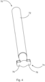
- Fig. 4 shows a brake release mechanism 70.
- the brake release mechanism 70 is configured for releasing the brake piston 8 against a force of the compression spring 18.
- the brake release mechanism 70 comprises a brake release bolt 72.
- the brake release bolt comprises a head section 74 comprising two locking protrusions 76. As shown in fig. 5 , these locking protrusions 76 are configured to interact with a receiving section 78 for releasing the spring brake piston 8 against the compression spring 18.
Landscapes
- Engineering & Computer Science (AREA)
- General Engineering & Computer Science (AREA)
- Mechanical Engineering (AREA)
- Transportation (AREA)
- Braking Arrangements (AREA)
- Braking Systems And Boosters (AREA)
Claims (14)
- Pneumatischer Federspeicherbremszylinder (2), insbesondere ein Feststell- und Dienstbremszylinder (2) für eine Verwendung in einem Nutzfahrzeug, der Federspeicherbremszylinder (2) umfassend:- ein Gehäuse (4) umfassend eine Gehäusebasis (6),- einen Federspeicherbremskolben (8), der mindestens teilweise in dem Gehäuse (4) untergebracht ist, wobei der Federspeicherbremskolben (8) konfiguriert ist, um sich zwischen einer festgehaltenen Position (10) und einer ausgefahrenen Position entlang einer Längsachse (14), abhängig von einem Druck im Inneren einer Federspeicherbremsdruckkammer (16) hin- und herzubewegen,- eine Druckfeder (18), die sich zwischen dem Gehäuse (4) und dem Federspeicherbremskolben (8) befindet, wobei die Druckfeder (18) wirksam ist, um den Federspeicherbremskolben (8) zu der ausgefahrenen Position hin zu drücken,
dadurch gekennzeichnet, dass der Federspeicherbremskolben (8) umfasst:- eine Betriebsbremsdruckkammer (20),- eine Kolbenkammer (22), und- einen Betriebsbremskolben (24), der die Betriebsbremsdruckkammer (20) von der Kolbenkammer (22) trennt, wobei der Betriebsbremskolben (24) konfiguriert ist, um sich zwischen einer festgehaltenen Position (26) und einer ausgefahrenen Position entlang der Längsachse (14), abhängig von einem Druck im Inneren der Betriebsbremsdruckkammer (20) hin- und herzubewegen, wobei der Federspeicherbremskolben (8) eine Vorderseite (30) umfasst, wobei die Vorderseite (30) gegenüber der Gehäusebasis (6) angeordnet ist, und sich ein erster Rohrabschnitt (32) von der Vorderseite (30) zu der Gehäusebasis (6) hin erstreckt, wobei der erste Rohrabschnitt (32) die Betriebsbremsdruckkammer (20) und die Kolbenkammer (22) radial begrenzt, dadurch gekennzeichnet, dass der Federspeicherbremskolben (8) einen zweiten Rohrabschnitt (34) umfasst, der sich koaxial um den ersten Rohrabschnitt (32) erstreckt, wobei der zweite Rohrabschnitt (34) einen radialen Vorsprung (36) umfasst, der an einer radialen Wand (38) des Gehäuses (4) anliegt, wobei ein Volumen zwischen dem zweiten Rohrabschnitt (34), dem Vorsprung (36) und der radialen Wand (38) die Federspeicherbremsdruckkammer (16) definiert. - Federspeicherbremszylinder (2) nach Anspruch 1,
wobei die Betriebsbremsdruckkammer (20) koaxial bezüglich der Längsachse (14) um die Federspeicherbremsdruckkammer (16) angeordnet ist. - Federspeicherbremszylinder (2) nach Anspruch 1 oder 2,
wobei der Vorsprung (36) eine Dichtung (40) umfasst, die konfiguriert ist, um den Vorsprung (36) gegen die radiale Gehäusewand (38) abzudichten. - Federspeicherbremszylinder (2) nach einem der vorstehenden Ansprüche, wobei der Zylinder (2) eine Führungshülse (42) umfasst, die mit der Gehäusebasis (6) verbunden ist, und wobei die Führungshülse (42) zum radialen Führen des Federspeicherbremskolbens (8) konfiguriert ist.
- Federspeicherbremszylinder (2) nach Anspruch 4,
wobei die Führungshülse (42) einen Hülsenabschnitt (44) zum radialen Führen des ersten Rohrabschnitts (32) des Federspeicherbremskolbens (8) und einen Flanschabschnitt (46), der benachbart zu dem Hülsenabschnitt (44) angeordnet ist, umfasst, wobei sich der Flanschabschnitt (46) von dem Hülsenabschnitt (44) radial erstreckt. - Federspeicherbremszylinder (2) nach Anspruch 5,
wobei der Flanschabschnitt (46) mit der Gehäusebasis (6) mittels einer Schraubverbindung (48) verbunden ist. - Federspeicherbremszylinder (2) nach Anspruch 1,
wobei der Zylinder (2) eine Kolbenfeder (50) umfasst, die im Inneren der Kolbenkammer (22) angeordnet ist, wobei die Kolbenfeder (50) wirksam ist, um den Federspeicherbremskolben (8) zu der Festhalteposition (26) hin zu drücken. - Federspeicherbremszylinder (2) nach Anspruch 1,
wobei das Gehäuse (4) einen Gehäuseflanschabschnitt (52), der sich radial nach außen von der radialen Gehäusewand (38) erstreckt, und einen Abdeckungsabschnitt (54), der an dem Flanschabschnitt (46) anliegt, umfasst, wobei der Abdeckungsabschnitt (54) eine Öffnung (56) umfasst, die zum Unterbringen des zweiten Rohrabschnitts (34) des Federspeicherbremskolbens (8) konfiguriert ist. - Federspeicherbremszylinder (2) nach Anspruch 8,
wobei der Abdeckungsabschnitt (54) einen Federspeicherbremsanschluss (58) zum Bereitstellen von druckbeaufschlagtem Fluid an die Federspeicherbremsdruckkammer (16) umfasst. - Federspeicherbremszylinder (2) nach Anspruch 9,
wobei sich der Federspeicherbremsanschluss (58) von dem Abdeckungsabschnitt (54) radial nach außen erstreckt. - Federspeicherbremszylinder (2) nach Anspruch 1,
wobei die Kolbenkammer (22) eine Stufe (60) zum Begrenzen einer Bewegung des Betriebsbremskolbens (24) zu der ausgefahrenen Position hin umfasst. - Federspeicherbremszylinder (2) nach Anspruch 1,
wobei die Gehäusebasis (6) einen Betriebsbremsenanschluss (62) zum Bereitstellen von druckbeaufschlagtem Fluid an die Betriebsbremsendruckkammer (20) umfasst, wobei der Betriebsbremsenanschluss (62) entlang der Längsachse (14) zentriert ist. - Federspeicherbremszylinder (2) nach Anspruch 1,
wobei der Zylinder (2) einen Bremslösemechanismus (70) umfasst, der zum Lösen des Federspeicherbremskolbens (8) gegen die Druckfeder (18) konfiguriert ist. - Federspeicherbremszylinder (2) nach Anspruch 12,
wobei der Betriebsbremsanschluss (62) konfiguriert ist, um den Lösemechanismus (70) mindestens teilweise unterzubringen.
Priority Applications (1)
| Application Number | Priority Date | Filing Date | Title |
|---|---|---|---|
| EP21167297.7A EP4071015B1 (de) | 2021-04-08 | 2021-04-08 | Pneumatischer federbremszylinder |
Applications Claiming Priority (1)
| Application Number | Priority Date | Filing Date | Title |
|---|---|---|---|
| EP21167297.7A EP4071015B1 (de) | 2021-04-08 | 2021-04-08 | Pneumatischer federbremszylinder |
Publications (2)
| Publication Number | Publication Date |
|---|---|
| EP4071015A1 EP4071015A1 (de) | 2022-10-12 |
| EP4071015B1 true EP4071015B1 (de) | 2024-08-14 |
Family
ID=75438572
Family Applications (1)
| Application Number | Title | Priority Date | Filing Date |
|---|---|---|---|
| EP21167297.7A Active EP4071015B1 (de) | 2021-04-08 | 2021-04-08 | Pneumatischer federbremszylinder |
Country Status (1)
| Country | Link |
|---|---|
| EP (1) | EP4071015B1 (de) |
Family Cites Families (4)
| Publication number | Priority date | Publication date | Assignee | Title |
|---|---|---|---|---|
| US6435321B1 (en) * | 2000-11-16 | 2002-08-20 | Nabco, Ltd | Brake cylinder apparatus |
| DE102004042992B4 (de) * | 2004-09-06 | 2006-08-03 | Knorr-Bremse Systeme für Nutzfahrzeuge GmbH | Kombinierter Betriebsbrems- und Federspeicherbremszylinder |
| DE502005006340D1 (de) * | 2004-09-21 | 2009-02-05 | Knorr Bremse Systeme | Bremszylinder für fahrzeugbremsen |
| DE102008010569A1 (de) * | 2008-02-22 | 2009-09-10 | Knorr-Bremse Systeme für Nutzfahrzeuge GmbH | Bremszylinder für druckluftbetätigte Fahrzeugbremsen |
-
2021
- 2021-04-08 EP EP21167297.7A patent/EP4071015B1/de active Active
Also Published As
| Publication number | Publication date |
|---|---|
| EP4071015A1 (de) | 2022-10-12 |
Similar Documents
| Publication | Publication Date | Title |
|---|---|---|
| US10941764B2 (en) | Piston pump assembly for a hydraulic power vehicle braking system | |
| US7523999B2 (en) | Brake cylinder for motor vehicle brakes | |
| EP2177411B1 (de) | Rutschdichtungsmembran für Federspeicherbremszylinder | |
| US20090211858A1 (en) | Hydraulic Vehicle Brake | |
| US3805924A (en) | Rear disc brake with integral ball ramp parking | |
| US10626939B2 (en) | Adhesive attachment of the disc brake pushrod plate to the diaphragm | |
| EP4071015B1 (de) | Pneumatischer federbremszylinder | |
| US10696284B2 (en) | Brake-pressure control device | |
| GB2174471A (en) | A clutch release mechanism | |
| EP0073549B1 (de) | Federkraft anwendende Betätigungsglieder | |
| GB2030651A (en) | Brake Actuators | |
| US20100326072A1 (en) | Booster | |
| EP2206633B1 (de) | Zweistufen-Nehmerzylinder | |
| EP3762268B1 (de) | Bremszylinder | |
| EP1917450B1 (de) | Selbstausrichtendes bremskit | |
| KR20130011798A (ko) | 가압식 인터널 듀얼 밸브를 적용한 피스톤 타입의 브레이크 액추에이터 | |
| CN112112912A (zh) | 弹簧制动器促动器和用于这种弹簧制动器促动器的制动器释放机构 | |
| US10239509B2 (en) | Primary piston assembly for a master brake cylinder of a braking system of a vehicle, manufacturing method for a braking unit, and method for operating a braking unit | |
| US5806648A (en) | Fluid pressure ram provided with a sliding intermediate chamber | |
| EP3406928A1 (de) | Federkraftbetätigte, hydraulisch gelöste bremse mit manueller übersteuerung | |
| JP2002137724A (ja) | マスタシリンダ | |
| CN102416936A (zh) | 快速充填串列主缸 | |
| EP4279347B1 (de) | Luftanschlussvorrichtung | |
| US12420766B2 (en) | Electromechanical brake pressure generator unit | |
| US12090972B2 (en) | Spring brake actuator |
Legal Events
| Date | Code | Title | Description |
|---|---|---|---|
| PUAI | Public reference made under article 153(3) epc to a published international application that has entered the european phase |
Free format text: ORIGINAL CODE: 0009012 |
|
| STAA | Information on the status of an ep patent application or granted ep patent |
Free format text: STATUS: THE APPLICATION HAS BEEN PUBLISHED |
|
| AK | Designated contracting states |
Kind code of ref document: A1 Designated state(s): AL AT BE BG CH CY CZ DE DK EE ES FI FR GB GR HR HU IE IS IT LI LT LU LV MC MK MT NL NO PL PT RO RS SE SI SK SM TR |
|
| STAA | Information on the status of an ep patent application or granted ep patent |
Free format text: STATUS: REQUEST FOR EXAMINATION WAS MADE |
|
| 17P | Request for examination filed |
Effective date: 20230412 |
|
| RBV | Designated contracting states (corrected) |
Designated state(s): AL AT BE BG CH CY CZ DE DK EE ES FI FR GB GR HR HU IE IS IT LI LT LU LV MC MK MT NL NO PL PT RO RS SE SI SK SM TR |
|
| GRAP | Despatch of communication of intention to grant a patent |
Free format text: ORIGINAL CODE: EPIDOSNIGR1 |
|
| STAA | Information on the status of an ep patent application or granted ep patent |
Free format text: STATUS: GRANT OF PATENT IS INTENDED |
|
| RIC1 | Information provided on ipc code assigned before grant |
Ipc: F16D 65/28 20060101ALI20240314BHEP Ipc: B60T 17/08 20060101AFI20240314BHEP |
|
| INTG | Intention to grant announced |
Effective date: 20240405 |
|
| GRAS | Grant fee paid |
Free format text: ORIGINAL CODE: EPIDOSNIGR3 |
|
| GRAA | (expected) grant |
Free format text: ORIGINAL CODE: 0009210 |
|
| STAA | Information on the status of an ep patent application or granted ep patent |
Free format text: STATUS: THE PATENT HAS BEEN GRANTED |
|
| AK | Designated contracting states |
Kind code of ref document: B1 Designated state(s): AL AT BE BG CH CY CZ DE DK EE ES FI FR GB GR HR HU IE IS IT LI LT LU LV MC MK MT NL NO PL PT RO RS SE SI SK SM TR |
|
| REG | Reference to a national code |
Ref country code: GB Ref legal event code: FG4D |
|
| REG | Reference to a national code |
Ref country code: CH Ref legal event code: EP |
|
| REG | Reference to a national code |
Ref country code: DE Ref legal event code: R096 Ref document number: 602021017068 Country of ref document: DE |
|
| REG | Reference to a national code |
Ref country code: IE Ref legal event code: FG4D |
|
| REG | Reference to a national code |
Ref country code: LT Ref legal event code: MG9D |
|
| REG | Reference to a national code |
Ref country code: NL Ref legal event code: MP Effective date: 20240814 |
|
| PG25 | Lapsed in a contracting state [announced via postgrant information from national office to epo] |
Ref country code: NO Free format text: LAPSE BECAUSE OF FAILURE TO SUBMIT A TRANSLATION OF THE DESCRIPTION OR TO PAY THE FEE WITHIN THE PRESCRIBED TIME-LIMIT Effective date: 20241114 |
|
| REG | Reference to a national code |
Ref country code: AT Ref legal event code: MK05 Ref document number: 1713025 Country of ref document: AT Kind code of ref document: T Effective date: 20240814 |
|
| PG25 | Lapsed in a contracting state [announced via postgrant information from national office to epo] |
Ref country code: NL Free format text: LAPSE BECAUSE OF FAILURE TO SUBMIT A TRANSLATION OF THE DESCRIPTION OR TO PAY THE FEE WITHIN THE PRESCRIBED TIME-LIMIT Effective date: 20240814 Ref country code: GR Free format text: LAPSE BECAUSE OF FAILURE TO SUBMIT A TRANSLATION OF THE DESCRIPTION OR TO PAY THE FEE WITHIN THE PRESCRIBED TIME-LIMIT Effective date: 20241115 Ref country code: PT Free format text: LAPSE BECAUSE OF FAILURE TO SUBMIT A TRANSLATION OF THE DESCRIPTION OR TO PAY THE FEE WITHIN THE PRESCRIBED TIME-LIMIT Effective date: 20241216 Ref country code: PL Free format text: LAPSE BECAUSE OF FAILURE TO SUBMIT A TRANSLATION OF THE DESCRIPTION OR TO PAY THE FEE WITHIN THE PRESCRIBED TIME-LIMIT Effective date: 20240814 Ref country code: FI Free format text: LAPSE BECAUSE OF FAILURE TO SUBMIT A TRANSLATION OF THE DESCRIPTION OR TO PAY THE FEE WITHIN THE PRESCRIBED TIME-LIMIT Effective date: 20240814 |
|
| PG25 | Lapsed in a contracting state [announced via postgrant information from national office to epo] |
Ref country code: BG Free format text: LAPSE BECAUSE OF FAILURE TO SUBMIT A TRANSLATION OF THE DESCRIPTION OR TO PAY THE FEE WITHIN THE PRESCRIBED TIME-LIMIT Effective date: 20240814 |
|
| PG25 | Lapsed in a contracting state [announced via postgrant information from national office to epo] |
Ref country code: LV Free format text: LAPSE BECAUSE OF FAILURE TO SUBMIT A TRANSLATION OF THE DESCRIPTION OR TO PAY THE FEE WITHIN THE PRESCRIBED TIME-LIMIT Effective date: 20240814 |
|
| PG25 | Lapsed in a contracting state [announced via postgrant information from national office to epo] |
Ref country code: IS Free format text: LAPSE BECAUSE OF FAILURE TO SUBMIT A TRANSLATION OF THE DESCRIPTION OR TO PAY THE FEE WITHIN THE PRESCRIBED TIME-LIMIT Effective date: 20241214 Ref country code: AT Free format text: LAPSE BECAUSE OF FAILURE TO SUBMIT A TRANSLATION OF THE DESCRIPTION OR TO PAY THE FEE WITHIN THE PRESCRIBED TIME-LIMIT Effective date: 20240814 |
|
| PG25 | Lapsed in a contracting state [announced via postgrant information from national office to epo] |
Ref country code: HR Free format text: LAPSE BECAUSE OF FAILURE TO SUBMIT A TRANSLATION OF THE DESCRIPTION OR TO PAY THE FEE WITHIN THE PRESCRIBED TIME-LIMIT Effective date: 20240814 |
|
| PG25 | Lapsed in a contracting state [announced via postgrant information from national office to epo] |
Ref country code: RS Free format text: LAPSE BECAUSE OF FAILURE TO SUBMIT A TRANSLATION OF THE DESCRIPTION OR TO PAY THE FEE WITHIN THE PRESCRIBED TIME-LIMIT Effective date: 20241114 Ref country code: ES Free format text: LAPSE BECAUSE OF FAILURE TO SUBMIT A TRANSLATION OF THE DESCRIPTION OR TO PAY THE FEE WITHIN THE PRESCRIBED TIME-LIMIT Effective date: 20240814 |
|
| PG25 | Lapsed in a contracting state [announced via postgrant information from national office to epo] |
Ref country code: RS Free format text: LAPSE BECAUSE OF FAILURE TO SUBMIT A TRANSLATION OF THE DESCRIPTION OR TO PAY THE FEE WITHIN THE PRESCRIBED TIME-LIMIT Effective date: 20241114 Ref country code: PT Free format text: LAPSE BECAUSE OF FAILURE TO SUBMIT A TRANSLATION OF THE DESCRIPTION OR TO PAY THE FEE WITHIN THE PRESCRIBED TIME-LIMIT Effective date: 20241216 Ref country code: PL Free format text: LAPSE BECAUSE OF FAILURE TO SUBMIT A TRANSLATION OF THE DESCRIPTION OR TO PAY THE FEE WITHIN THE PRESCRIBED TIME-LIMIT Effective date: 20240814 Ref country code: NO Free format text: LAPSE BECAUSE OF FAILURE TO SUBMIT A TRANSLATION OF THE DESCRIPTION OR TO PAY THE FEE WITHIN THE PRESCRIBED TIME-LIMIT Effective date: 20241114 Ref country code: NL Free format text: LAPSE BECAUSE OF FAILURE TO SUBMIT A TRANSLATION OF THE DESCRIPTION OR TO PAY THE FEE WITHIN THE PRESCRIBED TIME-LIMIT Effective date: 20240814 Ref country code: LV Free format text: LAPSE BECAUSE OF FAILURE TO SUBMIT A TRANSLATION OF THE DESCRIPTION OR TO PAY THE FEE WITHIN THE PRESCRIBED TIME-LIMIT Effective date: 20240814 Ref country code: IS Free format text: LAPSE BECAUSE OF FAILURE TO SUBMIT A TRANSLATION OF THE DESCRIPTION OR TO PAY THE FEE WITHIN THE PRESCRIBED TIME-LIMIT Effective date: 20241214 Ref country code: HR Free format text: LAPSE BECAUSE OF FAILURE TO SUBMIT A TRANSLATION OF THE DESCRIPTION OR TO PAY THE FEE WITHIN THE PRESCRIBED TIME-LIMIT Effective date: 20240814 Ref country code: GR Free format text: LAPSE BECAUSE OF FAILURE TO SUBMIT A TRANSLATION OF THE DESCRIPTION OR TO PAY THE FEE WITHIN THE PRESCRIBED TIME-LIMIT Effective date: 20241115 Ref country code: FI Free format text: LAPSE BECAUSE OF FAILURE TO SUBMIT A TRANSLATION OF THE DESCRIPTION OR TO PAY THE FEE WITHIN THE PRESCRIBED TIME-LIMIT Effective date: 20240814 Ref country code: ES Free format text: LAPSE BECAUSE OF FAILURE TO SUBMIT A TRANSLATION OF THE DESCRIPTION OR TO PAY THE FEE WITHIN THE PRESCRIBED TIME-LIMIT Effective date: 20240814 Ref country code: BG Free format text: LAPSE BECAUSE OF FAILURE TO SUBMIT A TRANSLATION OF THE DESCRIPTION OR TO PAY THE FEE WITHIN THE PRESCRIBED TIME-LIMIT Effective date: 20240814 Ref country code: AT Free format text: LAPSE BECAUSE OF FAILURE TO SUBMIT A TRANSLATION OF THE DESCRIPTION OR TO PAY THE FEE WITHIN THE PRESCRIBED TIME-LIMIT Effective date: 20240814 |
|
| PG25 | Lapsed in a contracting state [announced via postgrant information from national office to epo] |
Ref country code: RO Free format text: LAPSE BECAUSE OF FAILURE TO SUBMIT A TRANSLATION OF THE DESCRIPTION OR TO PAY THE FEE WITHIN THE PRESCRIBED TIME-LIMIT Effective date: 20240814 Ref country code: SM Free format text: LAPSE BECAUSE OF FAILURE TO SUBMIT A TRANSLATION OF THE DESCRIPTION OR TO PAY THE FEE WITHIN THE PRESCRIBED TIME-LIMIT Effective date: 20240814 Ref country code: DK Free format text: LAPSE BECAUSE OF FAILURE TO SUBMIT A TRANSLATION OF THE DESCRIPTION OR TO PAY THE FEE WITHIN THE PRESCRIBED TIME-LIMIT Effective date: 20240814 |
|
| PG25 | Lapsed in a contracting state [announced via postgrant information from national office to epo] |
Ref country code: EE Free format text: LAPSE BECAUSE OF FAILURE TO SUBMIT A TRANSLATION OF THE DESCRIPTION OR TO PAY THE FEE WITHIN THE PRESCRIBED TIME-LIMIT Effective date: 20240814 |
|
| PG25 | Lapsed in a contracting state [announced via postgrant information from national office to epo] |
Ref country code: CZ Free format text: LAPSE BECAUSE OF FAILURE TO SUBMIT A TRANSLATION OF THE DESCRIPTION OR TO PAY THE FEE WITHIN THE PRESCRIBED TIME-LIMIT Effective date: 20240814 |
|
| PGFP | Annual fee paid to national office [announced via postgrant information from national office to epo] |
Ref country code: FR Payment date: 20250310 Year of fee payment: 5 |
|
| PG25 | Lapsed in a contracting state [announced via postgrant information from national office to epo] |
Ref country code: IT Free format text: LAPSE BECAUSE OF FAILURE TO SUBMIT A TRANSLATION OF THE DESCRIPTION OR TO PAY THE FEE WITHIN THE PRESCRIBED TIME-LIMIT Effective date: 20240814 Ref country code: SK Free format text: LAPSE BECAUSE OF FAILURE TO SUBMIT A TRANSLATION OF THE DESCRIPTION OR TO PAY THE FEE WITHIN THE PRESCRIBED TIME-LIMIT Effective date: 20240814 |
|
| PGFP | Annual fee paid to national office [announced via postgrant information from national office to epo] |
Ref country code: GB Payment date: 20250306 Year of fee payment: 5 |
|
| REG | Reference to a national code |
Ref country code: DE Ref legal event code: R097 Ref document number: 602021017068 Country of ref document: DE |
|
| PLBE | No opposition filed within time limit |
Free format text: ORIGINAL CODE: 0009261 |
|
| STAA | Information on the status of an ep patent application or granted ep patent |
Free format text: STATUS: NO OPPOSITION FILED WITHIN TIME LIMIT |
|
| PGFP | Annual fee paid to national office [announced via postgrant information from national office to epo] |
Ref country code: DE Payment date: 20250305 Year of fee payment: 5 |
|
| 26N | No opposition filed |
Effective date: 20250515 |
|
| PG25 | Lapsed in a contracting state [announced via postgrant information from national office to epo] |
Ref country code: SE Free format text: LAPSE BECAUSE OF FAILURE TO SUBMIT A TRANSLATION OF THE DESCRIPTION OR TO PAY THE FEE WITHIN THE PRESCRIBED TIME-LIMIT Effective date: 20240814 |
|
| REG | Reference to a national code |
Ref country code: CH Ref legal event code: H13 Free format text: ST27 STATUS EVENT CODE: U-0-0-H10-H13 (AS PROVIDED BY THE NATIONAL OFFICE) Effective date: 20251125 |
|
| PG25 | Lapsed in a contracting state [announced via postgrant information from national office to epo] |
Ref country code: LU Free format text: LAPSE BECAUSE OF NON-PAYMENT OF DUE FEES Effective date: 20250408 |
|
| PG25 | Lapsed in a contracting state [announced via postgrant information from national office to epo] |
Ref country code: MC Free format text: LAPSE BECAUSE OF FAILURE TO SUBMIT A TRANSLATION OF THE DESCRIPTION OR TO PAY THE FEE WITHIN THE PRESCRIBED TIME-LIMIT Effective date: 20240814 |