EP4071003A1 - Occupant restraint device - Google Patents
Occupant restraint device Download PDFInfo
- Publication number
- EP4071003A1 EP4071003A1 EP20896743.0A EP20896743A EP4071003A1 EP 4071003 A1 EP4071003 A1 EP 4071003A1 EP 20896743 A EP20896743 A EP 20896743A EP 4071003 A1 EP4071003 A1 EP 4071003A1
- Authority
- EP
- European Patent Office
- Prior art keywords
- seat
- airbag
- seat airbag
- tension member
- restraining device
- Prior art date
- Legal status (The legal status is an assumption and is not a legal conclusion. Google has not performed a legal analysis and makes no representation as to the accuracy of the status listed.)
- Pending
Links
- 230000000452 restraining effect Effects 0.000 claims abstract description 51
- 238000004804 winding Methods 0.000 claims description 4
- 239000000463 material Substances 0.000 description 7
- 238000003780 insertion Methods 0.000 description 4
- 230000037431 insertion Effects 0.000 description 4
- 238000001514 detection method Methods 0.000 description 3
- 210000003127 knee Anatomy 0.000 description 3
- 210000000689 upper leg Anatomy 0.000 description 3
- 238000005516 engineering process Methods 0.000 description 2
- 230000000149 penetrating effect Effects 0.000 description 2
- 238000010586 diagram Methods 0.000 description 1
- 230000000694 effects Effects 0.000 description 1
- 239000004744 fabric Substances 0.000 description 1
- 238000000034 method Methods 0.000 description 1
- 230000001737 promoting effect Effects 0.000 description 1
- 238000009958 sewing Methods 0.000 description 1
- 230000001629 suppression Effects 0.000 description 1
Images


Classifications
-
- B—PERFORMING OPERATIONS; TRANSPORTING
- B60—VEHICLES IN GENERAL
- B60N—SEATS SPECIALLY ADAPTED FOR VEHICLES; VEHICLE PASSENGER ACCOMMODATION NOT OTHERWISE PROVIDED FOR
- B60N2/00—Seats specially adapted for vehicles; Arrangement or mounting of seats in vehicles
- B60N2/24—Seats specially adapted for vehicles; Arrangement or mounting of seats in vehicles for particular purposes or particular vehicles
- B60N2/42—Seats specially adapted for vehicles; Arrangement or mounting of seats in vehicles for particular purposes or particular vehicles the seat constructed to protect the occupant from the effect of abnormal g-forces, e.g. crash or safety seats
- B60N2/427—Seats or parts thereof displaced during a crash
- B60N2/42727—Seats or parts thereof displaced during a crash involving substantially rigid displacement
- B60N2/42754—Seats or parts thereof displaced during a crash involving substantially rigid displacement of the cushion
- B60N2/42763—Seats or parts thereof displaced during a crash involving substantially rigid displacement of the cushion with anti-submarining systems
-
- B—PERFORMING OPERATIONS; TRANSPORTING
- B60—VEHICLES IN GENERAL
- B60N—SEATS SPECIALLY ADAPTED FOR VEHICLES; VEHICLE PASSENGER ACCOMMODATION NOT OTHERWISE PROVIDED FOR
- B60N2/00—Seats specially adapted for vehicles; Arrangement or mounting of seats in vehicles
- B60N2/24—Seats specially adapted for vehicles; Arrangement or mounting of seats in vehicles for particular purposes or particular vehicles
- B60N2/42—Seats specially adapted for vehicles; Arrangement or mounting of seats in vehicles for particular purposes or particular vehicles the seat constructed to protect the occupant from the effect of abnormal g-forces, e.g. crash or safety seats
- B60N2/427—Seats or parts thereof displaced during a crash
-
- B—PERFORMING OPERATIONS; TRANSPORTING
- B60—VEHICLES IN GENERAL
- B60R—VEHICLES, VEHICLE FITTINGS, OR VEHICLE PARTS, NOT OTHERWISE PROVIDED FOR
- B60R21/00—Arrangements or fittings on vehicles for protecting or preventing injuries to occupants or pedestrians in case of accidents or other traffic risks
- B60R21/02—Occupant safety arrangements or fittings, e.g. crash pads
- B60R21/06—Safety nets, transparent sheets, curtains, or the like, e.g. between occupants and glass
- B60R21/08—Safety nets, transparent sheets, curtains, or the like, e.g. between occupants and glass automatically movable from an inoperative to an operative position, e.g. in a collision
-
- B—PERFORMING OPERATIONS; TRANSPORTING
- B60—VEHICLES IN GENERAL
- B60R—VEHICLES, VEHICLE FITTINGS, OR VEHICLE PARTS, NOT OTHERWISE PROVIDED FOR
- B60R21/00—Arrangements or fittings on vehicles for protecting or preventing injuries to occupants or pedestrians in case of accidents or other traffic risks
- B60R21/02—Occupant safety arrangements or fittings, e.g. crash pads
- B60R21/16—Inflatable occupant restraints or confinements designed to inflate upon impact or impending impact, e.g. air bags
- B60R21/20—Arrangements for storing inflatable members in their non-use or deflated condition; Arrangement or mounting of air bag modules or components
- B60R21/207—Arrangements for storing inflatable members in their non-use or deflated condition; Arrangement or mounting of air bag modules or components in vehicle seats
-
- B—PERFORMING OPERATIONS; TRANSPORTING
- B60—VEHICLES IN GENERAL
- B60R—VEHICLES, VEHICLE FITTINGS, OR VEHICLE PARTS, NOT OTHERWISE PROVIDED FOR
- B60R21/00—Arrangements or fittings on vehicles for protecting or preventing injuries to occupants or pedestrians in case of accidents or other traffic risks
- B60R21/02—Occupant safety arrangements or fittings, e.g. crash pads
- B60R21/16—Inflatable occupant restraints or confinements designed to inflate upon impact or impending impact, e.g. air bags
- B60R21/23—Inflatable members
- B60R21/231—Inflatable members characterised by their shape, construction or spatial configuration
- B60R21/2334—Expansion control features
- B60R21/2338—Tethers
-
- B—PERFORMING OPERATIONS; TRANSPORTING
- B60—VEHICLES IN GENERAL
- B60R—VEHICLES, VEHICLE FITTINGS, OR VEHICLE PARTS, NOT OTHERWISE PROVIDED FOR
- B60R21/00—Arrangements or fittings on vehicles for protecting or preventing injuries to occupants or pedestrians in case of accidents or other traffic risks
- B60R21/02—Occupant safety arrangements or fittings, e.g. crash pads
- B60R21/16—Inflatable occupant restraints or confinements designed to inflate upon impact or impending impact, e.g. air bags
- B60R21/23—Inflatable members
- B60R21/237—Inflatable members characterised by the way they are folded
-
- B—PERFORMING OPERATIONS; TRANSPORTING
- B60—VEHICLES IN GENERAL
- B60R—VEHICLES, VEHICLE FITTINGS, OR VEHICLE PARTS, NOT OTHERWISE PROVIDED FOR
- B60R21/00—Arrangements or fittings on vehicles for protecting or preventing injuries to occupants or pedestrians in case of accidents or other traffic risks
- B60R21/02—Occupant safety arrangements or fittings, e.g. crash pads
- B60R21/16—Inflatable occupant restraints or confinements designed to inflate upon impact or impending impact, e.g. air bags
- B60R21/23—Inflatable members
- B60R21/231—Inflatable members characterised by their shape, construction or spatial configuration
- B60R21/2334—Expansion control features
- B60R21/2338—Tethers
- B60R2021/23386—External tether means
- B60R2021/23388—External tether means having ends which are movable or detachable during deployment
Definitions
- the present technology relates to an occupant restraining device that restrains an occupant of a vehicle in the event of a collision.
- the band When the side airbag expands and deploys, the band is pushed from the side airbag and tension is generated in the band. The tension presses the side airbag against a sitting occupant, restraining and protecting the occupant.
- Patent Document 1 Japanese Unexamined Patent Application 2019-137319
- an object of the present disclosure is to provide an occupant restraining device that enables promoting occupant restraint using side airbags.
- An occupant restraining device for restraining an occupant seated in a vehicle seat having a seatback and seat cushion, including:
- the occupant restraining device wherein the traction portion has a rotating body, and rotation of the rotating body pulls the tension member toward the center of the vehicle seat.
- the occupant restraining device wherein the traction portion has a retractor, and winding of the retractor pulls the tension member toward the center of the vehicle seat.
- the occupant restraining device according to an Embodiment of the present disclosure is provided so that the tension member passes through the upper surface of the in-seat airbag.
- the tension member has a through hole for inserting, and a support portion that movably supports the tension member is provided on the outside of the in-seat airbag.
- the occupant restraining device according to an Embodiment of the present disclosure, wherein the tension member is arranged so as to pass in front of the in-seat airbag when the in-seat airbag expands and deploys.
- the occupant restraining device wherein the in-seat airbag is folded so as to overlap vertically and the portion of the in-seat airbag that the tension member is arranged on is sandwiched by the in-seat airbag in the vertical direction and is attached in the front-to-back length-wise direction of the in-seat airbag in the front-to-back direction in plan view.
- the in-seat airbag further includes: a rolled member that is rolled in the front-to-back direction of the in-seat airbag, the rolled member includes:
- the occupant restraining device wherein the rolled member is configured so that the connecting portion with the folded portion of the tension member is arranged at the front end portion of the in-seat airbag when the in-seat airbag expands and deploys.
- the occupant restraining device according to an Embodiment of the present disclosure, wherein the folded portion is folded at least once and is connected to the tension member at the uppermost portion of the rolled member folded portion.
- the occupant restraining device wherein the in-seat airbag is secured to a frame body of the vehicle seat and both front and back end portions of the rolled member are secured to the in-seat airbag or frame body via both front and back end portions of the in-seat airbag.
- a tension member is provided in the in-seat airbag stowed inside of or below the seat cushion and the tension member is caused to move by expansion and deployment of the airbag.
- the tension member arranged on the side of the seat back is pulled toward the center and the front of the seat, the side airbag is arranged in front of the occupant, and the side airbag is pressed toward the occupant side by the tension member and can promote restraint of occupants.
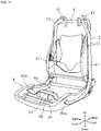
- FIG. 1 is an external perspective view of the seat 1.
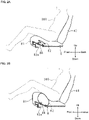
- FIG. 2A is a schematic left side partial cross-sectional view of the seat 1 in which an in-seat airbag 82 is folded.
- FIG. 2B is a schematic left side partial cross-sectional view of the seat 1 with the in-seat airbag 82 deployed.
- FIG. 3 is a perspective view illustrating the seat 1 to which an occupant restraining device is attached.
- the cushion material of the seating portion is referred to as a seat cushion 81.
- the seat 1 includes a frame body, a cushion material covering the frame body, and a surface skin covering the cushion material.
- the dashed line indicates a frame covered with cushion material.
- the frame body of the seat 1 has a first frame body 4 of the seatback and a second frame body 8 of the seating portion.
- the first frame body 4 is covered by a seatback cushion 40
- the second frame body 8 is covered by the seat cushion 81.
- the first frame body 4 of the seatback and the second frame body 8 of the seating portion are substantially rectangular.
- the area close to the right shoulder of the occupant is referred to as the right side of the first frame body 4 of the seatback
- the area close to the left shoulder of the occupant is referred to as the left side of the first frame body 4 of the seatback
- the occupant is seated on the front side of the first frame body 4 of the seatback.
- a headrest 7 is provided on the upper side of the first frame body 4 of the seatback.
- An occupant restraining device 100 includes an airbag module 1 (not shown).
- the airbag module is provided on the outside of long side frames 41 (side portions of the seat back) on both the left and right sides of the first frame body 4, respectively. Note, the airbag module may be provided only on one of the long side frames 41.
- the airbag module includes a side airbag 3 (see FIG. 7 ), described below, and an inflator (not shown) that receives an output signal from a sensor and emits gas.
- the side airbag 3 is folded.
- the side airbag 3 includes, for example, the circumference of two base materials sewn together to form a bag shape, and the inflator is arranged inside the side airbag 3.
- the occupant restraining device 100 protects an occupant by deploying the side airbag 3 in the front direction of the seat during a vehicle collision.
- a tension band 2 (tension member) described below is sewn onto upper and lower middle points of the side airbag 3 and the side airbag 3 is restrained by the tension band 2.
- the occupant restraining device 100 further includes a tension band 2.
- the tension band 2 is a band having a prescribed width, and two left side bands 21, 21 arranged on the left side of the first frame body 4, two right side bands 22, 22 arranged on the right side of the first frame body 4, and one lower band 23 arranged on the second frame body 8 are provided.
- the first ends of the two left side bands 21, 21 are connected and attached to an attachment 42 provided on the left upper side of the first frame body 4.
- the left band 21 is arranged over the outside of the left side long side frame 41 and the outside of the left portion of the second frame body 8.
- the first ends of the two right side bands 22, 22 are connected and attached to an attachment 42 provided on the right upper side of the first frame body 4.
- the right band 22 is arranged over the outside of the right side long side frame 41 and the outside of the right portion of the second frame body 8.
- the other ends of the two left side bands 21, 21 are connected to a first end of the lower band 23, and the second ends of the two right side bands 22, 22 are connected to a second end of the lower band 23.
- FIG. 3 only one right band 22 is illustrated. Note, there may be one left band 21 or there may be three or more. Note, there may be one right band 22 or there may be three or more.
- a stowing recessed portion 80 having a rectangular shape in a plan view is formed on the upper surface of the second frame body 8.
- a seat pan 86 is provided on the front side of the stowing recessed portion 80. Note, in FIG. 3 , the description of the seat pan 86 is omitted for ease of understanding.
- the seat pan 86 is provided with an in-seat airbag 82 and is covered with a seat cushion 81.
- the in-seat airbag 82 includes an inflator 82a.
- the in-seat airbag 82 is folded.
- the in-seat airbag 82 is arranged under the seat cushion 81.
- the in-seat airbag 82 may be arranged inside the seat cushion 81.
- the in-seat airbag 82 may be provided on the front side of the stowing recessed portion 80 without providing the seat pan 86.
- the inflator 82a is electrically connected to the vehicle-side ECU.
- the inflator 82a is activated by receiving an impact detection signal in the event of a vehicle frontal collision from the vehicle-side ECU and instantaneously supplies gas to the in-seat airbag 82.
- the inflator 82a can be one of various types of inflators, such as inflators filled with a gas generating agent, compressed gas, or both, and the like.
- the supply of gas causes the in-seat airbag 82 to expand and deploy, the front portion of the seat cushion 81 to rise, and the knee or thigh portion of an occupant 300 to be lifted. Lifting the knees or thighs restrains the forward movement of the hips of the occupant 300.
- FIG. 4 is a schematic front partial cross-sectional view of the in-seat airbag 82, a support portion 83, and the lower band 23.
- Two support portions 83 are provided on the bottom surface of the stowing recessed portion 80.
- the two support portions 83 are provided on the right side and the left side of the in-seat airbag 82, respectively.
- the support portion 83 has a through hole 83a penetrating in the left-right direction.
- An in-seat airbag 82 is arranged between the two support portions 83.
- the lower band 23 is movably inserted into the through hole 83a of each support portion 83, and is connected to the upper surface of the in-seat airbag 82.
- Methods of connecting the lower band 23 to the upper surface include, for example, joining the lower band 23 and the upper surface by sewing, or attaching a guide that can be inserted into the lower band 23 to the upper surface of the in-seat airbag 82 and connecting the lower band 23 to the upper surface via this guide.
- slits 80a extending back and forth are formed on each of the left and right side surfaces of the second frame body 8.
- the slit 80a penetrates in the left-right direction and causes the inner space of the stowing recessed portion 80 to communicate with the space outside the second frame body 8.
- the lower band 23 or the left band 21 is movably inserted into the slit 80a on the left side.
- the lower band 23 or the right band 22 is movably inserted into the slit 80a on the right side.
- FIG. 5 is a perspective view illustrating the occupant restraining device 100 with the in-seat airbag 82 expanded and deployed.
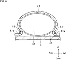
- FIG. 6 is a schematic front partial cross-sectional view of the in-seat airbag 82, the support portion 83, and the lower band 23 when the in-seat airbag 82 is expanded and deployed.
- the lower band 23 is pulled up and the left side bands 21, 21 and the right side bands 22, 22 are pulled by the expansion and deployment of the in-seat airbag 82. In other words, tension is applied to the tension band 2.
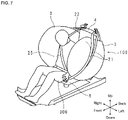
- FIG. 7 is a perspective view illustrating the occupant restraining device 100 and the seat 1 when the side airbag 3 and the in-seat airbag 82 are expanded and deployed.
- the headrest 7 is omitted.
- the tension band 2 is sewn to the side airbag 3.
- a first side airbag 3 is arranged between the left side bands 21, 21 and the left side long side frame 41, and a second side airbag 3 is arranged between the right side bands 22, 22 and the right side long side frame 41. Based on the expansion and deployment of the side airbag 3, the left band 21 is pulled to the left side and the right band 22 is pulled to the right side.
- the expansion and deployment of the in-seat airbag 82 lifts the knee or thigh of the occupant 300; suppressing forward movement of the waist of the occupant 300. Further, the expansion and deployment of the in-seat airbag 82 causes the left band 21 and the right band 22 to be pulled toward the center and the front of the seat. In other words, the left band 21 and the right band 22 can push the side airbags 3 toward the occupant and restrain the occupant 300 in combination with suppression of the forward movement of the waist portion. As illustrated in FIG. 7 , using a normal three-point seat belt 25 further improves the restraining effect of the occupant 300.
- the tension band 2 is joined to the in-seat airbag 82 stowed inside or below the seat cushion 81, and the tension band 2 is moved by expansion and deployment of the in-seat airbag 82. Therefore, the tension band 2 arranged on the side of the first frame body 4 of the seatback is pulled toward the center and the front of the seat, and in combination with suppressing the forward movement of the waist of the occupant 300, promotes restraining of the occupant by the side airbag 3.
- the tension band 2 is not limited to the case where two bands are provided on the left and right.
- One band may be provided on each of the left and right, or three or more bands may be provided on the left and right.
- the side airbag 3 may be provided on only one of either the left or right side long side frame 41.
- Embodiment 2 the same configurations as those of Embodiment 1 are designated by the same codes, and detailed descriptions thereof are omitted.
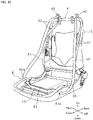
- FIG. 8 is a perspective view illustrating the seat to which the folded in-seat airbag 82 is attached.
- FIG. 9 is a schematic right side view illustrating the in-seat airbag 82 in a folded state and an expanded state.
- FIG. 10 is a perspective view illustrating the seat to which the expanded and deployed in-seat airbag 82 is attached.
- the upper view of FIG. 9 illustrates the in-seat airbag 82 in a folded state
- the lower view of FIG. 9 illustrates the in-seat airbag 82 in an expanded state.
- the dashed line in FIG. 9 illustrates the position of the lower band 23 of the folded state and the expanded state.
- the seat cushion 81 is omitted.
- the folded in-seat airbag 82 is stowed in the stowing recessed portion 80.
- the front portion of the in-seat airbag 82 is folded so as to be overlapped on the top and bottom.
- the lower band 23 is connected to the outer surface of the in-seat airbag 82 and is sandwiched between two overlapping in-seat airbags 82.
- the lower band 23 is connected to the lower portion of the overlapping in-seat airbag 82.
- the lower band 23 is attached between the central portion and the rear end portion of the folded in-seat airbag 82.
- the lower band 23 may be connected to the lower portion of the overlapping in-seat airbag 82.
- the folded in-seat airbag 82 is folded two times, but may be folded three or more times.
- the lower band 23 moves forward when the in-seat airbag 82 expands and deploys. As illustrated in FIG. 10 , forward movement of the lower band 23 pulls the left band 21 and the right band 22 toward the center and front of the seat. Therefore, the left band 21 and the right band 22 can push the side airbags 3 toward the occupant and restrain the occupant in combination with suppressing forward movement of the waist of the occupant 300.
- Embodiment 3 the same configurations as those of Embodiment 1 or 2 are designated by the same codes, and detailed descriptions thereof are omitted.
- FIG. 11 is a perspective view illustrating the seat to which the folded in-seat airbag 82 and cover 84 are attached.
- FIG. 12 is a schematic right side view illustrating the in-seat airbag 82 and cover 84 in a folded state and an expanded state.
- FIG. 13 is a perspective view illustrating the seat to which the expanded and deployed in-seat airbag 82 and cover 84 are attached.
- the upper view of FIG. 12 illustrates the in-seat airbag 82 in a folded state
- the lower view of FIG. 12 illustrates the in-seat airbag 82 in an expanded state.
- the dashed line in FIG. 12 illustrates the position of the lower band 23 of the folded state and the expanded state.
- the seat cushion 81 is omitted.
- the folded in-seat airbag 82 (bag) is stowed in the stowing recessed portion 80.
- the in-seat airbag 82 is covered with a cover 84 (wrapping member).
- cover 84 wrapped member
- the front end portion and the rear end portion of the cover 84 are secured to the second frame body 8 by the securing member 85, respectively.
- the front end portion and the rear end portion of the cover 84 may be secured to the front end portion and the rear end portion of the in-seat airbag 82.
- the cover 84 is folded back at least once on the upper surface of the in-seat airbag 82.
- the folded portion of the cover 84 includes, for example, a folded portion folded in a bellows shape.
- the lower band 23 is connected to the uppermost portion of the folded portion of the cover 84.
- the lower band 23 is attached to the upper surface of the uppermost portion.
- the folded portion of the cover 84 may be provided on the lower surface of the in-seat airbag 82, and the lower band 23 may be attached to the folded portion of the cover 84 provided on the lower surface.
- FIG. 14 is a schematic front cross-sectional view of the second frame body 8.
- a rotating body 91 having an elongated shape is stowed in the stowing recessed portion 80.
- a pivot 90 is provided at the center of the rotating body 91 in the longitudinal direction.
- the pivot 90 extends in a direction orthogonal to the longitudinal direction of the rotating body 91.
- the rotating body 91 is arranged so that the axial direction of the pivot 90 is in the front-rear direction.
- the rotating body 91 can rotate around the pivot 90.
- An inflator 92 is stowed in the stowing recessed portion 80.
- the inflator 92 includes a rod 92a.
- the rod 92a extends from the body of the inflator 92 and can push the rotating body 91.
- the inflator 92 is arranged on the left side of the rotating body 91 and below the pivot 90, and the rod 92a pushes the lower left portion of the rotating body 91 to the left.
- the inflator 92 may be arranged on the right side of the rotating body 91 and above the pivot 90, and the rod 92a may push the upper right portion of the rotating body 91 to the left side.
- the occupant restraining device 100 includes a first lower band 23a and a second lower band 23b.
- a first end of the first lower band 23a is connected to the lower left portion of the rotating body 91, and a second end of the first lower band 23a is connected to the lower ends of the two left side bands 21, 21.
- a first end of a second lower band 23b is connected to the upper right portion of the rotating body 91, and a second end of the second lower band 23b is connected to the lower ends of the two right side bands 22, 22.
- the first lower band 23a and the left band 21 are arranged so as to enable insertion into the left side slit 80a and the second lower band 23b and right band 22 are arranged so as to enable insertion into the right side slit 80a.
- FIG. 15 is a schematic front cross-sectional view of the second frame body 8 where the rod 92a is advanced.
- the inflator 92 is electrically connected to the vehicle-side ECU.
- the inflator 92 is activated by receiving an impact detection signal in the event of a vehicle frontal collision from the vehicle-side ECU and, as illustrated in FIG. 15 , advances the rod 92a.
- the rotating body 91 rotates, the first lower band 23a and the left band 21 are pulled toward the inside of the stowing recessed portion 80, and the second lower band 23b and the right band 22 are also pulled toward the inside of the stowing recessed portion 80.
- the left band 21 and the right band 22 are pulled toward the center of the seat. Therefore, the left band 21 and the right band 22 can push the side airbag 3 toward the occupant to restrain the occupant.
- the rotating body 91 is highly responsive to the drive of the inflator 92. Therefore, the left band 21 and the right band 22 are pulled immediately after the inflator 92 drive starts.
- the side airbag 3 can be deployed toward the occupant from the initial stage of expansion and deployment of the side airbag 3.
- the rotation axis direction of the rotating body 91 is the front-to-back direction but the rotation axis direction is not limited to this and, for example, the rotation axis direction may be the vertical direction.
- FIG. 16 is a schematic front cross-sectional view of the second frame body 8 using one lower band 23.
- the first lower band 23a and the second lower band 23b that is, two lower bands are used, but as illustrated in FIG. 16 , one of the lower bands 23 is bent in a Z or S shape and the first end and second end of the portion bent in a Z or S shape may be connected to the rotating body 91 by a connecting member 93 such as a pin.
- the first end of the lower band 23 is connected to the left band 21, and the second end is connected to the right band 22.
- FIG. 17 is a schematic front cross-sectional view of the second frame body 8.
- a retractor 94 and two guide rollers 95, 95 are stowed in the stowing recessed portion 80.
- the two guide rollers 95, 95 are respectively arranged on the left and the right of the upper side of the retractor 94.
- the retractor 94 includes a spindle (not shown) that rotates with the front-rear direction as an axial direction for winding the seat belt, and a motor (not shown) that supplies power to the spindle. Further, a first connecting belt 94a and two second connecting belts 94b, 94b are provided. A first end of the first connecting belt 94a is connected to the spindle, and a second end of the first connecting belt 94a extends outward from the main body of the retractor 94. As illustrated in FIG. 17 , in the initial state, the second end of the first connecting belt 94a is positioned between the two guide rollers 95, 95, and is connected respectively to the first ends of the two second connecting belts 94b. The two second connecting belts 94b are arranged on the left and right respectively, and are guided by the two guide rollers 95, 95, respectively.
- the second end of the left second connecting belt 94b is connected to the lower ends of the two left side bands 21, 21 via the first lower band 23a.
- the second end of the right second connecting belt 94b is connected to the lower ends of the two right side bands 22, 22 via the second lower band 23b.
- the left second connecting belt 94b and the left band 21 are arranged so as to enable insertion into the left side slit 80a and the right second connecting belt 94b and right band 22 are arranged so as to enable insertion into the right side slit 80a.
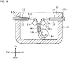
- FIG. 18 is a schematic front cross-sectional view of the second frame body 8 where the retractor 94 has been activated.
- the retractor 94 is electrically connected to the vehicle-side ECU.
- the retractor 94 is activated by receiving an impact detection signal in the event of a vehicle frontal collision from the vehicle-side ECU, causes the motor to rotate, and causes the spindle to rotate as illustrated by the white arrow in FIG. 18 .
- the first connecting belt 94a, the second connecting belt 94b, the first lower band 23a and the second lower band 23b are wound around the retractor 94, and the left band 21 and the right band 22 are pulled toward the inside of the stowing recessed portion 80.
- the left band 21 and the right band 22 are pulled toward the center of the seat. Therefore, the left band 21 and the right band 22 can push the side airbag 3 toward the occupant to restrain the occupant.
- the retractor 94 can wind up the first connecting belt 94a, the second connecting belt 94b, the first lower band 23a, the second lower band 23b, the left band 21, and the right band 22.
- the winding amount of the retractor 94 is determined according to the specifications of the vehicle.
- the retractor 94 is highly responsive to the motor drive. Therefore, the left band 21 and the right band 22 are pulled immediately after the motor drive starts.
- the side airbag 3 can be deployed toward the occupant from the initial stage of expansion and deployment of the side airbag 3.
- the rotation axis direction of the retractor 94 spindle is the front-to-back direction but the rotation axis direction is not limited to this and, for example, the rotation axis direction may be the vertical direction.
- the in-seat airbag may be stowed in or below the seat cushion 81.
Abstract
a side airbag (3) arranged on at least one of the right side or the left side of the seat back;
a tension member (2) arranged over the side portion of the seat back and the seat cushion and a portion thereof provided on the outer surface of the side airbag; and
a traction portion on which another portion of the tension member is provided, that is stowed on the inside of or below the seat cushion, and that can pull the tension member, wherein
the tension member arranged on the side of the seatback is pulled toward the center of the vehicle seat by the traction portion.
Description
- The present technology relates to an occupant restraining device that restrains an occupant of a vehicle in the event of a collision.
- Conventionally, an occupant restraining device including side airbags provided on the left and right sides of the seatback and a tension cloth (band) attached to the outer surface of the side airbags has been proposed (see, for example, Patent Document 1).
- When the side airbag expands and deploys, the band is pushed from the side airbag and tension is generated in the band. The tension presses the side airbag against a sitting occupant, restraining and protecting the occupant.
- [Patent Document 1]
Japanese Unexamined Patent Application 2019-137319 - In recent years, there has been further demand for side airbags to reliably restrain occupants.
- In light of these circumstances, an object of the present disclosure is to provide an occupant restraining device that enables promoting occupant restraint using side airbags.
- An occupant restraining device according to an Embodiment of the present disclosure for restraining an occupant seated in a vehicle seat having a seatback and seat cushion, including:
- a side airbag arranged on at least one of the right side and the left side of the seat back;
- a tension member arranged over the side portion of the seat back and the seat cushion and a portion thereof provided on the outer surface of the side airbag; and
- a traction portion on which another portion of the tension member is provided, that is stowed on the inside of or below the seat cushion, and that can pull the tension member, wherein
- the tension member arranged on the side of the seatback is pulled toward the center of the vehicle seat by the traction portion.
- The occupant restraining device according to an Embodiment of the present disclosure, wherein the traction portion has a rotating body, and rotation of the rotating body pulls the tension member toward the center of the vehicle seat.
- The occupant restraining device according to an Embodiment of the present disclosure, wherein the traction portion has a retractor, and winding of the retractor pulls the tension member toward the center of the vehicle seat.
- The occupant restraining device according to an Embodiment of the present disclosure is provided so that the tension member passes through the upper surface of the in-seat airbag.
- The occupant restraining device according to an Embodiment of the present disclosure, wherein the in-seat airbag is secured to the seat cushion, the tension member has a through hole for inserting, and a support portion that movably supports the tension member is provided on the outside of the in-seat airbag.
- The occupant restraining device according to an Embodiment of the present disclosure, wherein the tension member is arranged so as to pass in front of the in-seat airbag when the in-seat airbag expands and deploys.
- The occupant restraining device according to an Embodiment of the present disclosure, wherein the in-seat airbag is folded so as to overlap vertically and the portion of the in-seat airbag that the tension member is arranged on is sandwiched by the in-seat airbag in the vertical direction and is attached in the front-to-back length-wise direction of the in-seat airbag in the front-to-back direction in plan view.
- The occupant restraining device according to an Embodiment of the present disclosure, wherein
the in-seat airbag further includes:
a rolled member that is rolled in the front-to-back direction of the in-seat airbag, the rolled member includes: - a folded member folded in a bellows shape on the upper surface or lower surface on the rear portion of the in-seat airbag enabling extending the length of the rolled up perimeter of the rolled member during expansion and deployment of the seat cushion, and
- the tension member is connected to the folded portion.
- The occupant restraining device according to an Embodiment of the present disclosure, wherein the rolled member is configured so that the connecting portion with the folded portion of the tension member is arranged at the front end portion of the in-seat airbag when the in-seat airbag expands and deploys.
- The occupant restraining device according to an Embodiment of the present disclosure, wherein the folded portion is folded at least once and is connected to the tension member at the uppermost portion of the rolled member folded portion.
- The occupant restraining device according to an Embodiment of the present disclosure, wherein the in-seat airbag is secured to a frame body of the vehicle seat and both front and back end portions of the rolled member are secured to the in-seat airbag or frame body via both front and back end portions of the in-seat airbag.
- In the occupant restraint device according to an embodiment of the present disclosure, a tension member is provided in the in-seat airbag stowed inside of or below the seat cushion and the tension member is caused to move by expansion and deployment of the airbag. Thereby, the tension member arranged on the side of the seat back is pulled toward the center and the front of the seat, the side airbag is arranged in front of the occupant, and the side airbag is pressed toward the occupant side by the tension member and can promote restraint of occupants.
-
-
FIG. 1 is an external perspective view of a seat according toEmbodiment 1. -
FIG. 2A is a schematic left side partial cross-sectional view of the seat in which an in-seat airbag is folded. -
FIG. 2B is a schematic left side partial cross-sectional view of the in-seat airbag deployed. -
FIG. 3 is a perspective view illustrating the seat to which the occupant restraining device according toEmbodiment 1 is attached (side airbags are not shown). -
FIG. 4 is a schematic front partial cross-sectional view of an in-seat airbag, a support portion, and a lower band. -
FIG. 5 is a perspective view illustrating an occupant restraining device when the in-seat airbag is expanded and deployed (side airbags are not shown). -
FIG. 6 is a schematic front partial cross-sectional view of the in-seat airbag, the support portion, and the lower band when the in-seat airbag is expanded and deployed. -
FIG. 7 is a perspective view illustrating the occupant restraining device and the seat when the side airbag and the in-seat airbag are expanded and deployed. -
FIG. 8 is a perspective view illustrating the seat to which the folded in-seat airbag according toEmbodiment 2 is attached. -
FIG. 9 is a schematic right side view illustrating the in-seat airbag in a folded state and an expanded state. -
FIG. 10 is a perspective view illustrating the seat with the in-seat airbag that has been expanded and deployed attached (side airbag not shown). -
FIG. 11 is a perspective view illustrating the folded in-seat airbag and the seat with a cover attached according to Embodiment 3 (side airbag not shown). -
FIG. 12 is a schematic right side view illustrating the in-seat airbag and cover in a folded state and an expanded state. -
FIG. 13 is a perspective view illustrating the seat with the in-seat airbag and cover that has been expanded and deployed attached (side airbag not shown). -
FIG. 14 is a schematic front cross-sectional view of a second frame body according to Embodiment 4. -
FIG. 15 is a schematic front cross-sectional view of the second frame body where a rod is advanced. -
FIG. 16 is a schematic front cross-sectional view of the second frame body using one lower band. -
FIG. 17 is a schematic front cross-sectional view of the second frame body according to Embodiment 5. -
FIG. 18 is a schematic front cross-sectional view of the second frame body where a retractor has been activated. - Hereinafter, the present invention will be described with reference to the drawings illustrating the occupant restraining device according to
Embodiment 1. In the following description, the top, bottom, front, back, left, and right indicated in the diagram are used.FIG. 1 is an external perspective view of theseat 1.FIG. 2A is a schematic left side partial cross-sectional view of theseat 1 in which an in-seat airbag 82 is folded.FIG. 2B is a schematic left side partial cross-sectional view of theseat 1 with the in-seat airbag 82 deployed.FIG. 3 is a perspective view illustrating theseat 1 to which an occupant restraining device is attached. InFIG. 3 , for convenience of description, only the frame of theseat 1 is illustrated; namely, the surface skin of theseat 1, the cushion material of the seatback, and the cushion material of the seating portion are not illustrated. Hereinafter, the cushion material of the seating portion is referred to as aseat cushion 81. - The
seat 1 includes a frame body, a cushion material covering the frame body, and a surface skin covering the cushion material. InFIG. 1 , the dashed line indicates a frame covered with cushion material. As illustrated inFIG. 1 , the frame body of theseat 1 has afirst frame body 4 of the seatback and asecond frame body 8 of the seating portion. Thefirst frame body 4 is covered by aseatback cushion 40, and thesecond frame body 8 is covered by theseat cushion 81. Thefirst frame body 4 of the seatback and thesecond frame body 8 of the seating portion are substantially rectangular. In the following, when an occupant sits in the aforementioned seat normally, the area close to the right shoulder of the occupant is referred to as the right side of thefirst frame body 4 of the seatback, and the area close to the left shoulder of the occupant is referred to as the left side of thefirst frame body 4 of the seatback, and the occupant is seated on the front side of thefirst frame body 4 of the seatback. A headrest 7 is provided on the upper side of thefirst frame body 4 of the seatback. - An
occupant restraining device 100 includes an airbag module 1 (not shown). The airbag module is provided on the outside of long side frames 41 (side portions of the seat back) on both the left and right sides of thefirst frame body 4, respectively. Note, the airbag module may be provided only on one of the long side frames 41. - The airbag module includes a side airbag 3 (see
FIG. 7 ), described below, and an inflator (not shown) that receives an output signal from a sensor and emits gas. Theside airbag 3 is folded. Theside airbag 3 includes, for example, the circumference of two base materials sewn together to form a bag shape, and the inflator is arranged inside theside airbag 3. Theoccupant restraining device 100 protects an occupant by deploying theside airbag 3 in the front direction of the seat during a vehicle collision. A tension band 2 (tension member) described below is sewn onto upper and lower middle points of theside airbag 3 and theside airbag 3 is restrained by thetension band 2. - The
occupant restraining device 100 further includes atension band 2. Thetension band 2 is a band having a prescribed width, and twoleft side bands first frame body 4, tworight side bands first frame body 4, and onelower band 23 arranged on thesecond frame body 8 are provided. The first ends of the twoleft side bands attachment 42 provided on the left upper side of thefirst frame body 4. Theleft band 21 is arranged over the outside of the left sidelong side frame 41 and the outside of the left portion of thesecond frame body 8. The first ends of the tworight side bands attachment 42 provided on the right upper side of thefirst frame body 4. Theright band 22 is arranged over the outside of the right sidelong side frame 41 and the outside of the right portion of thesecond frame body 8. - The other ends of the two
left side bands lower band 23, and the second ends of the tworight side bands lower band 23. InFIG. 3 , only oneright band 22 is illustrated. Note, there may be oneleft band 21 or there may be three or more. Note, there may be oneright band 22 or there may be three or more. - As illustrated in
FIG. 3 , a stowing recessedportion 80 having a rectangular shape in a plan view is formed on the upper surface of thesecond frame body 8. As illustrated inFIG. 2A , aseat pan 86 is provided on the front side of the stowing recessedportion 80. Note, inFIG. 3 , the description of theseat pan 86 is omitted for ease of understanding. Theseat pan 86 is provided with an in-seat airbag 82 and is covered with aseat cushion 81. The in-seat airbag 82 includes aninflator 82a. The in-seat airbag 82 is folded. The in-seat airbag 82 is arranged under theseat cushion 81. The in-seat airbag 82 may be arranged inside theseat cushion 81. The in-seat airbag 82 may be provided on the front side of the stowing recessedportion 80 without providing theseat pan 86. - The
inflator 82a is electrically connected to the vehicle-side ECU. For example, theinflator 82a is activated by receiving an impact detection signal in the event of a vehicle frontal collision from the vehicle-side ECU and instantaneously supplies gas to the in-seat airbag 82. Theinflator 82a can be one of various types of inflators, such as inflators filled with a gas generating agent, compressed gas, or both, and the like. As illustrated inFIG. 2B , the supply of gas causes the in-seat airbag 82 to expand and deploy, the front portion of theseat cushion 81 to rise, and the knee or thigh portion of anoccupant 300 to be lifted. Lifting the knees or thighs restrains the forward movement of the hips of theoccupant 300. -
FIG. 4 is a schematic front partial cross-sectional view of the in-seat airbag 82, asupport portion 83, and thelower band 23. Twosupport portions 83 are provided on the bottom surface of the stowing recessedportion 80. The twosupport portions 83 are provided on the right side and the left side of the in-seat airbag 82, respectively. Thesupport portion 83 has a throughhole 83a penetrating in the left-right direction.
An in-seat airbag 82 is arranged between the twosupport portions 83. Thelower band 23 is movably inserted into the throughhole 83a of eachsupport portion 83, and is connected to the upper surface of the in-seat airbag 82. Methods of connecting thelower band 23 to the upper surface include, for example, joining thelower band 23 and the upper surface by sewing, or attaching a guide that can be inserted into thelower band 23 to the upper surface of the in-seat airbag 82 and connecting thelower band 23 to the upper surface via this guide. - As illustrated in
FIG. 3 , slits 80a extending back and forth are formed on each of the left and right side surfaces of thesecond frame body 8. Theslit 80a penetrates in the left-right direction and causes the inner space of the stowing recessedportion 80 to communicate with the space outside thesecond frame body 8. Thelower band 23 or theleft band 21 is movably inserted into theslit 80a on the left side. Thelower band 23 or theright band 22 is movably inserted into theslit 80a on the right side. -
FIG. 5 is a perspective view illustrating theoccupant restraining device 100 with the in-seat airbag 82 expanded and deployed.FIG. 6 is a schematic front partial cross-sectional view of the in-seat airbag 82, thesupport portion 83, and thelower band 23 when the in-seat airbag 82 is expanded and deployed. - As illustrated in
FIG. 5 andFIG. 6 , thelower band 23 is pulled up and theleft side bands right side bands seat airbag 82. In other words, tension is applied to thetension band 2. -
FIG. 7 is a perspective view illustrating theoccupant restraining device 100 and theseat 1 when theside airbag 3 and the in-seat airbag 82 are expanded and deployed. InFIG. 7 , the headrest 7 is omitted. As described above, thetension band 2 is sewn to theside airbag 3. Afirst side airbag 3 is arranged between theleft side bands long side frame 41, and asecond side airbag 3 is arranged between theright side bands long side frame 41.
Based on the expansion and deployment of theside airbag 3, theleft band 21 is pulled to the left side and theright band 22 is pulled to the right side. As described above, the expansion and deployment of the in-seat airbag 82 lifts the knee or thigh of theoccupant 300; suppressing forward movement of the waist of theoccupant 300. Further, the expansion and deployment of the in-seat airbag 82 causes theleft band 21 and theright band 22 to be pulled toward the center and the front of the seat. In other words, theleft band 21 and theright band 22 can push theside airbags 3 toward the occupant and restrain theoccupant 300 in combination with suppression of the forward movement of the waist portion. As illustrated inFIG. 7 , using a normal three-point seat belt 25 further improves the restraining effect of theoccupant 300.
In the occupant restraining device according toEmbodiment 1, thetension band 2 is joined to the in-seat airbag 82 stowed inside or below theseat cushion 81, and thetension band 2 is moved by expansion and deployment of the in-seat airbag 82. Therefore, thetension band 2 arranged on the side of thefirst frame body 4 of the seatback is pulled toward the center and the front of the seat, and in combination with suppressing the forward movement of the waist of theoccupant 300, promotes restraining of the occupant by theside airbag 3. - Note, the
tension band 2 is not limited to the case where two bands are provided on the left and right. One band may be provided on each of the left and right, or three or more bands may be provided on the left and right. Further, theside airbag 3 may be provided on only one of either the left or right sidelong side frame 41. - Hereinafter, the present invention will be described with reference to the drawings illustrating the
occupant restraining device 100 according toEmbodiment 2. Of the configurations according toEmbodiment 2, the same configurations as those ofEmbodiment 1 are designated by the same codes, and detailed descriptions thereof are omitted. -
FIG. 8 is a perspective view illustrating the seat to which the folded in-seat airbag 82 is attached.FIG. 9 is a schematic right side view illustrating the in-seat airbag 82 in a folded state and an expanded state.FIG. 10 is a perspective view illustrating the seat to which the expanded and deployed in-seat airbag 82 is attached. The upper view ofFIG. 9 illustrates the in-seat airbag 82 in a folded state, and the lower view ofFIG. 9 illustrates the in-seat airbag 82 in an expanded state. In addition, the dashed line inFIG. 9 illustrates the position of thelower band 23 of the folded state and the expanded state. InFIGS. 8 and10 , theseat cushion 81 is omitted. - As illustrated in
FIG. 8 , the folded in-seat airbag 82 is stowed in the stowing recessedportion 80. As illustrated in the upper view ofFIG. 9 , the front portion of the in-seat airbag 82 is folded so as to be overlapped on the top and bottom. Thelower band 23 is connected to the outer surface of the in-seat airbag 82 and is sandwiched between two overlapping in-seat airbags 82. Thelower band 23 is connected to the lower portion of the overlapping in-seat airbag 82. In the front-to-back direction, thelower band 23 is attached between the central portion and the rear end portion of the folded in-seat airbag 82.
Note, thelower band 23 may be connected to the lower portion of the overlapping in-seat airbag 82. In the upper view ofFIG. 9 , the folded in-seat airbag 82 is folded two times, but may be folded three or more times. - As indicated by the arrows in the lower view of
FIG. 9 , thelower band 23 moves forward when the in-seat airbag 82 expands and deploys. As illustrated inFIG. 10 , forward movement of thelower band 23 pulls theleft band 21 and theright band 22 toward the center and front of the seat. Therefore, theleft band 21 and theright band 22 can push theside airbags 3 toward the occupant and restrain the occupant in combination with suppressing forward movement of the waist of theoccupant 300. - Hereinafter, the present invention will be described with reference to the drawings illustrating the
occupant restraining device 100 according toEmbodiment 3. Of the configurations according toEmbodiment 3, the same configurations as those ofEmbodiment -
FIG. 11 is a perspective view illustrating the seat to which the folded in-seat airbag 82 and cover 84 are attached.FIG. 12 is a schematic right side view illustrating the in-seat airbag 82 and cover 84 in a folded state and an expanded state.FIG. 13 is a perspective view illustrating the seat to which the expanded and deployed in-seat airbag 82 and cover 84 are attached. The upper view ofFIG. 12 illustrates the in-seat airbag 82 in a folded state, and the lower view ofFIG. 12 illustrates the in-seat airbag 82 in an expanded state. In addition, the dashed line inFIG. 12 illustrates the position of thelower band 23 of the folded state and the expanded state. InFIG. 11 andFIG. 13 , theseat cushion 81 is omitted. - As illustrated in
FIG. 11 , the folded in-seat airbag 82 (bag) is stowed in the stowing recessedportion 80. The in-seat airbag 82 is covered with a cover 84 (wrapping member). As illustrated in the upper view ofFIG. 12 , in the vicinity of the front end portion and the rear end portion of the in-seat airbag 82, the front end portion and the rear end portion of thecover 84 are secured to thesecond frame body 8 by the securingmember 85, respectively. The front end portion and the rear end portion of thecover 84 may be secured to the front end portion and the rear end portion of the in-seat airbag 82. - As illustrated in the upper view of
FIG. 12 , on the upper side of the in-seat airbag 82, thecover 84 is folded back at least once on the upper surface of the in-seat airbag 82. The folded portion of thecover 84 includes, for example, a folded portion folded in a bellows shape. Thelower band 23 is connected to the uppermost portion of the folded portion of thecover 84. Thelower band 23 is attached to the upper surface of the uppermost portion. The folded portion of thecover 84 may be provided on the lower surface of the in-seat airbag 82, and thelower band 23 may be attached to the folded portion of thecover 84 provided on the lower surface. - In the lower view of
FIG. 12 , as indicated by the arrows, when the in-seat airbag 82 expands and deploys, thecover 84 and thelower band 23 move forward, and the connecting portion between thelower band 23 and thecover 84 is arranged at the front end portion of the in-seat airbag 82. As illustrated inFIG. 13 , forward movement of thelower band 23 pulls theleft band 21 and theright band 22 toward the center and front of the seat. Therefore, theleft band 21 and theright band 22 can push theside airbags 3 toward the occupant and restrain the occupant in combination with suppressing forward movement of the waist of theoccupant 300. - Hereinafter, the present invention will be described with reference to the drawings illustrating the
occupant restraining device 100 according toEmbodiment 4. Of the configurations according toEmbodiment 4, the same configurations as those ofEmbodiment 1 to 3 are designated by the same codes, and detailed descriptions thereof are omitted.FIG. 14 is a schematic front cross-sectional view of thesecond frame body 8. - A rotating
body 91 having an elongated shape is stowed in the stowing recessedportion 80. Apivot 90 is provided at the center of therotating body 91 in the longitudinal direction. Thepivot 90 extends in a direction orthogonal to the longitudinal direction of therotating body 91. The rotatingbody 91 is arranged so that the axial direction of thepivot 90 is in the front-rear direction. The rotatingbody 91 can rotate around thepivot 90. - An inflator 92 is stowed in the stowing recessed
portion 80. The inflator 92 includes arod 92a. Therod 92a extends from the body of the inflator 92 and can push therotating body 91. InFIG. 14 , theinflator 92 is arranged on the left side of therotating body 91 and below thepivot 90, and therod 92a pushes the lower left portion of therotating body 91 to the left. The inflator 92 may be arranged on the right side of therotating body 91 and above thepivot 90, and therod 92a may push the upper right portion of therotating body 91 to the left side. - The
occupant restraining device 100 includes a first lower band 23a and a secondlower band 23b. A first end of the first lower band 23a is connected to the lower left portion of therotating body 91, and a second end of the first lower band 23a is connected to the lower ends of the twoleft side bands lower band 23b is connected to the upper right portion of therotating body 91, and a second end of the secondlower band 23b is connected to the lower ends of the tworight side bands left band 21 are arranged so as to enable insertion into the left side slit 80a and the secondlower band 23b andright band 22 are arranged so as to enable insertion into the right side slit 80a. -
FIG. 15 is a schematic front cross-sectional view of thesecond frame body 8 where therod 92a is advanced. The inflator 92 is electrically connected to the vehicle-side ECU. For example, theinflator 92 is activated by receiving an impact detection signal in the event of a vehicle frontal collision from the vehicle-side ECU and, as illustrated inFIG. 15 , advances therod 92a. - As illustrated by the white arrows in
FIG. 15 , the rotatingbody 91 rotates, the first lower band 23a and theleft band 21 are pulled toward the inside of the stowing recessedportion 80, and the secondlower band 23b and theright band 22 are also pulled toward the inside of the stowing recessedportion 80. On the left and right sides of the seat, theleft band 21 and theright band 22 are pulled toward the center of the seat. Therefore, theleft band 21 and theright band 22 can push theside airbag 3 toward the occupant to restrain the occupant. - The rotating
body 91 is highly responsive to the drive of theinflator 92. Therefore, theleft band 21 and theright band 22 are pulled immediately after the inflator 92 drive starts. Theside airbag 3 can be deployed toward the occupant from the initial stage of expansion and deployment of theside airbag 3. InEmbodiment 4, the rotation axis direction of therotating body 91 is the front-to-back direction but the rotation axis direction is not limited to this and, for example, the rotation axis direction may be the vertical direction. -
FIG. 16 is a schematic front cross-sectional view of thesecond frame body 8 using onelower band 23. InEmbodiment 4, the first lower band 23a and the secondlower band 23b, that is, two lower bands are used, but as illustrated inFIG. 16 , one of thelower bands 23 is bent in a Z or S shape and the first end and second end of the portion bent in a Z or S shape may be connected to therotating body 91 by a connectingmember 93 such as a pin. In this case, the first end of thelower band 23 is connected to theleft band 21, and the second end is connected to theright band 22. - Hereinafter, the present invention will be described with reference to the drawings illustrating the
occupant restraining device 100 according to Embodiment 5. Of the configurations according to Embodiment 5, the same configurations as those ofEmbodiment 1 to 4 are designated by the same codes, and detailed descriptions thereof are omitted.FIG. 17 is a schematic front cross-sectional view of thesecond frame body 8.
Aretractor 94 and twoguide rollers portion 80. The twoguide rollers retractor 94. Theretractor 94 includes a spindle (not shown) that rotates with the front-rear direction as an axial direction for winding the seat belt, and a motor (not shown) that supplies power to the spindle. Further, a first connecting belt 94a and two second connectingbelts retractor 94.
As illustrated inFIG. 17 , in the initial state, the second end of the first connecting belt 94a is positioned between the twoguide rollers belts 94b. The two second connectingbelts 94b are arranged on the left and right respectively, and are guided by the twoguide rollers - The second end of the left second connecting
belt 94b is connected to the lower ends of the twoleft side bands belt 94b is connected to the lower ends of the tworight side bands lower band 23b. The left second connectingbelt 94b and theleft band 21 are arranged so as to enable insertion into the left side slit 80a and the right second connectingbelt 94b andright band 22 are arranged so as to enable insertion into the right side slit 80a. -
FIG. 18 is a schematic front cross-sectional view of thesecond frame body 8 where theretractor 94 has been activated. Theretractor 94 is electrically connected to the vehicle-side ECU. For example, theretractor 94 is activated by receiving an impact detection signal in the event of a vehicle frontal collision from the vehicle-side ECU, causes the motor to rotate, and causes the spindle to rotate as illustrated by the white arrow inFIG. 18 . - As illustrated by the arrows in
FIG. 18 , the first connecting belt 94a, the second connectingbelt 94b, the first lower band 23a and the secondlower band 23b are wound around theretractor 94, and theleft band 21 and theright band 22 are pulled toward the inside of the stowing recessedportion 80. On the left and right sides of the seat, theleft band 21 and theright band 22 are pulled toward the center of the seat. Therefore, theleft band 21 and theright band 22 can push theside airbag 3 toward the occupant to restrain the occupant. - The
retractor 94 can wind up the first connecting belt 94a, the second connectingbelt 94b, the first lower band 23a, the secondlower band 23b, theleft band 21, and theright band 22. The winding amount of theretractor 94 is determined according to the specifications of the vehicle. - The
retractor 94 is highly responsive to the motor drive. Therefore, theleft band 21 and theright band 22 are pulled immediately after the motor drive starts. Theside airbag 3 can be deployed toward the occupant from the initial stage of expansion and deployment of theside airbag 3. In Embodiment 5, the rotation axis direction of theretractor 94 spindle is the front-to-back direction but the rotation axis direction is not limited to this and, for example, the rotation axis direction may be the vertical direction. - In
Embodiments 4 and 5, the in-seat airbag may be stowed in or below theseat cushion 81. - When a reference code is noted in a claim, the reference code is merely provided as a reference in correspondence with the reference code described in the embodiment in order to facilitate understanding of the claim. The scope of claims is not limited to the embodiments.
- The embodiments presently disclosed are to be considered as examples for all points, and are not restrictive. The technical features described in the examples can be combined with each other, and the scope of the invention is intended to include all changes within the scope of the claims and a scope equal to the claims.
-
- 2: Tension band (tension member)
- 21: Left band
- 22: Right band
- 23: Lower band
- 3: Side airbag
- 4: First frame body (seatback)
- 8: Second frame body (frame body)
- 81: Seat cushion
- 82: In-seat airbag
- 83: Support portion
- 83a: Penetrating hole
- 84: Cover (wrapping member)
- 91: Rotating body
- 94: Retractor
- 100: Occupant restraining device
Claims (12)
- An occupant restraining device for restraining an occupant seated in a vehicle seat having a seatback (4) and seat cushion (81), comprising:a side airbag (3) arranged on at least one of the right side or the left side of the seat back;a tension member (2) arranged over the side portion of the seat back and the seat cushion and a portion thereof provided on the outer surface of the side airbag; anda traction portion on which another portion of the tension member is provided, that is stowed on the inside of or below the seat cushion, and that can pull the tension member, whereinthe tension member arranged on the side of the seatback is pulled toward the center of the vehicle seat by the traction portion.
- The occupant restraining device according to claim 1, wherein the traction portion has a rotating body (91), and rotation of the rotating body pulls the tension member toward the center of the vehicle seat.
- The occupant restraining device according to claim 1, wherein the traction portion has a retractor (94), and winding of the retractor pulls the tension member toward the center of the vehicle seat.
- The occupant restraining device according to claim 1, wherein the traction portion has an in-seat airbag (82) that can expand and deploy and expansion and deployment of the in-seat airbag pulls the tension member toward the center of the vehicle seat.
- The occupant restraining device according to claim 4, wherein the tension member is provided on the upper surface of the in-seat airbag.
- The occupant restraining device according to claim 5, wherein the in-seat airbag is secured to the seat cushion, the tension member has a through hole for inserting, and a support portion (83) that movably supports the tension member is provided on the outside of the in-seat airbag.
- The occupant restraining device according to claim 4, wherein the tension member is arranged so as to pass in front of the in-seat airbag when the in-seat airbag expands and deploys.
- The occupant restraining device according to claim 7, wherein the in-seat airbag is folded so as to overlap vertically and the portion of the in-seat airbag that the tension member is arranged on is sandwiched by the in-seat airbag in the vertical direction and is attached in the front-to-back length-wise direction of the in-seat airbag in plan view.
- The occupant restraining device according to claim 4, wherein
the in-seat airbag further includes:a rolled member (84) that is rolled in the front-to-back direction of the in-seat airbag,the rolled member includes:a folded member folded in a bellows shape on the upper surface or lower surface on the rear portion of the in-seat airbag enabling extending the length of the rolled up perimeter of the rolled member during expansion and deployment of the seat cushion, andthe tension member is connected to the folded portion. - The occupant restraining device according to claim 9, wherein the rolled member is configured so that the connecting portion with the folded portion of the tension member is arranged at the front end portion of the in-seat airbag when the in-seat airbag expands and deploys.
- The occupant restraining device according to claim 9 or 10, wherein the folded portion is folded at least once and is connected to the tension member at the uppermost portion of the rolled member folded portion.
- The occupant restraining device according to any one of claims 9 to 11, wherein the in-seat airbag is secured to a frame body (8) of the vehicle seat and both front and back end portions of the rolled member are secured to the in-seat airbag or frame body via both front and back end portions of the in-seat airbag.
Applications Claiming Priority (2)
| Application Number | Priority Date | Filing Date | Title |
|---|---|---|---|
| JP2019221471 | 2019-12-06 | ||
| PCT/JP2020/039402 WO2021111748A1 (en) | 2019-12-06 | 2020-10-20 | Occupant restraint device |
Publications (2)
| Publication Number | Publication Date |
|---|---|
| EP4071003A1 true EP4071003A1 (en) | 2022-10-12 |
| EP4071003A4 EP4071003A4 (en) | 2024-01-10 |
Family
ID=76222512
Family Applications (1)
| Application Number | Title | Priority Date | Filing Date |
|---|---|---|---|
| EP20896743.0A Pending EP4071003A4 (en) | 2019-12-06 | 2020-10-20 | Occupant restraint device |
Country Status (5)
| Country | Link |
|---|---|
| US (1) | US20230012314A1 (en) |
| EP (1) | EP4071003A4 (en) |
| JP (1) | JP7217366B2 (en) |
| KR (1) | KR20220107282A (en) |
| WO (1) | WO2021111748A1 (en) |
Families Citing this family (7)
| Publication number | Priority date | Publication date | Assignee | Title |
|---|---|---|---|---|
| CN110035923B (en) * | 2016-11-01 | 2022-04-19 | 施罗特安全产品股份有限责任公司 | Airbag system and method for repositioning an occupant in the event of a collision |
| EP4035954A4 (en) * | 2019-09-23 | 2023-11-01 | Autoliv Development AB | Airbag device and vehicle seat |
| JP7341321B2 (en) * | 2020-04-01 | 2023-09-08 | オートリブ ディベロップメント エービー | Occupant protection device |
| EP4321393A1 (en) * | 2021-04-09 | 2024-02-14 | Autoliv Development AB | Occupant restraint device and production method for occupant restraint device |
| FR3126371B1 (en) * | 2021-08-26 | 2023-09-15 | Renault Sas | Vehicle seat with on-board safety system |
| DE102022106752A1 (en) * | 2022-03-23 | 2023-09-28 | Audi Aktiengesellschaft | Vehicle seat |
| DE102022124259A1 (en) * | 2022-09-21 | 2024-03-21 | Audi Aktiengesellschaft | Tether mechanism for an airbag module |
Family Cites Families (10)
| Publication number | Priority date | Publication date | Assignee | Title |
|---|---|---|---|---|
| US6029993A (en) * | 1997-10-06 | 2000-02-29 | Inova Gmbh Technische Entwicklungen | Side airbag device, method for operation thereof and vehicle seat therewith |
| JP2002211354A (en) * | 2001-01-18 | 2002-07-31 | Takata Corp | Pretensioner device |
| JP2008201297A (en) | 2007-02-21 | 2008-09-04 | Toyota Motor Corp | Vehicle side airbag device |
| JP2011240746A (en) | 2010-05-14 | 2011-12-01 | Denso Corp | Seat belt device |
| WO2013108473A1 (en) | 2012-01-17 | 2013-07-25 | オートリブ ディベロップメント エービー | Air bag device |
| JP5799841B2 (en) | 2012-02-03 | 2015-10-28 | トヨタ自動車株式会社 | Vehicle seat |
| JP5796552B2 (en) * | 2012-07-04 | 2015-10-21 | トヨタ自動車株式会社 | Vehicle seat |
| JP6762328B2 (en) * | 2018-02-14 | 2020-09-30 | オートリブ ディベロップメント エービー | Crew restraint device |
| JP6670510B2 (en) * | 2018-03-30 | 2020-03-25 | 株式会社Subaru | Vehicle occupant protection device |
| KR102070212B1 (en) | 2018-06-01 | 2020-01-28 | 엘지전자 주식회사 | Wireless charger for mobile terminal |
-
2020
- 2020-10-20 JP JP2021562487A patent/JP7217366B2/en active Active
- 2020-10-20 EP EP20896743.0A patent/EP4071003A4/en active Pending
- 2020-10-20 WO PCT/JP2020/039402 patent/WO2021111748A1/en unknown
- 2020-10-20 KR KR1020227022667A patent/KR20220107282A/en not_active Application Discontinuation
- 2020-10-20 US US17/756,732 patent/US20230012314A1/en active Pending
Also Published As
| Publication number | Publication date |
|---|---|
| JP7217366B2 (en) | 2023-02-02 |
| US20230012314A1 (en) | 2023-01-12 |
| CN114650935A (en) | 2022-06-21 |
| WO2021111748A1 (en) | 2021-06-10 |
| KR20220107282A (en) | 2022-08-02 |
| EP4071003A4 (en) | 2024-01-10 |
| JPWO2021111748A1 (en) | 2021-06-10 |
Similar Documents
| Publication | Publication Date | Title |
|---|---|---|
| EP4071003A1 (en) | Occupant restraint device | |
| US7896390B2 (en) | Air belt system | |
| JP5382199B2 (en) | Side airbag device for vehicle | |
| JP4174515B2 (en) | Air belt device for vehicle | |
| EP2559598B1 (en) | Air belt device | |
| JP5850008B2 (en) | Air belt device | |
| JP2011025909A (en) | Side airbag device | |
| KR102556814B1 (en) | passenger restraint device | |
| US11590920B2 (en) | Seat-centric airbag system with pelvis restraint chamber | |
| US8789849B2 (en) | Dual depth airbag | |
| JP2019147426A (en) | Vehicle occupant protection device | |
| CN114423649A (en) | Vehicle airbag system | |
| US11498509B2 (en) | Roof mounted passenger airbag | |
| JP2008296722A (en) | Occupant protection device | |
| KR20220075368A (en) | Airbag device and vehicle seat | |
| JP6499093B2 (en) | Crew protection device | |
| JP7341321B2 (en) | Occupant protection device | |
| EP4159552A1 (en) | Airbag device | |
| CN114650935B (en) | Occupant restraint device | |
| JP2007125937A (en) | Air belt device for vehicle | |
| CN215971413U (en) | Seat and vehicle | |
| KR20070070296A (en) | Cover unification typed air belt of safety belt in vehicle | |
| KR20190108688A (en) | Air bag device for seat belt | |
| JP7458359B2 (en) | Vehicle side airbag device | |
| US20230415695A1 (en) | Safety restraint system for lower extremities in automated driving |
Legal Events
| Date | Code | Title | Description |
|---|---|---|---|
| STAA | Information on the status of an ep patent application or granted ep patent |
Free format text: STATUS: THE INTERNATIONAL PUBLICATION HAS BEEN MADE |
|
| PUAI | Public reference made under article 153(3) epc to a published international application that has entered the european phase |
Free format text: ORIGINAL CODE: 0009012 |
|
| STAA | Information on the status of an ep patent application or granted ep patent |
Free format text: STATUS: REQUEST FOR EXAMINATION WAS MADE |
|
| 17P | Request for examination filed |
Effective date: 20220621 |
|
| AK | Designated contracting states |
Kind code of ref document: A1 Designated state(s): AL AT BE BG CH CY CZ DE DK EE ES FI FR GB GR HR HU IE IS IT LI LT LU LV MC MK MT NL NO PL PT RO RS SE SI SK SM TR |
|
| DAV | Request for validation of the european patent (deleted) | ||
| DAX | Request for extension of the european patent (deleted) | ||
| REG | Reference to a national code |
Ref country code: DE Ref legal event code: R079 Free format text: PREVIOUS MAIN CLASS: B60R0021080000 Ipc: B60N0002427000 |
|
| A4 | Supplementary search report drawn up and despatched |
Effective date: 20231211 |
|
| RIC1 | Information provided on ipc code assigned before grant |
Ipc: B60R 21/08 20060101ALI20231205BHEP Ipc: B60R 21/237 20060101ALI20231205BHEP Ipc: B60R 21/2338 20110101ALI20231205BHEP Ipc: B60R 21/207 20060101ALI20231205BHEP Ipc: B60N 2/427 20060101AFI20231205BHEP |