EP4070935B1 - Siegelvorrichtung für eine verpackungsmaschine, verpackungsmaschine mit einer siegelvorrichtung und verfahren zum betrieb einer siegelvorrichtung - Google Patents
Siegelvorrichtung für eine verpackungsmaschine, verpackungsmaschine mit einer siegelvorrichtung und verfahren zum betrieb einer siegelvorrichtung Download PDFInfo
- Publication number
- EP4070935B1 EP4070935B1 EP22166637.3A EP22166637A EP4070935B1 EP 4070935 B1 EP4070935 B1 EP 4070935B1 EP 22166637 A EP22166637 A EP 22166637A EP 4070935 B1 EP4070935 B1 EP 4070935B1
- Authority
- EP
- European Patent Office
- Prior art keywords
- piezoelectric transducer
- temperature
- sealing device
- sealing
- transducer devices
- Prior art date
- Legal status (The legal status is an assumption and is not a legal conclusion. Google has not performed a legal analysis and makes no representation as to the accuracy of the status listed.)
- Active
Links
Images



Classifications
-
- B—PERFORMING OPERATIONS; TRANSPORTING
- B29—WORKING OF PLASTICS; WORKING OF SUBSTANCES IN A PLASTIC STATE IN GENERAL
- B29C—SHAPING OR JOINING OF PLASTICS; SHAPING OF MATERIAL IN A PLASTIC STATE, NOT OTHERWISE PROVIDED FOR; AFTER-TREATMENT OF THE SHAPED PRODUCTS, e.g. REPAIRING
- B29C65/00—Joining or sealing of preformed parts, e.g. welding of plastics materials; Apparatus therefor
- B29C65/02—Joining or sealing of preformed parts, e.g. welding of plastics materials; Apparatus therefor by heating, with or without pressure
- B29C65/08—Joining or sealing of preformed parts, e.g. welding of plastics materials; Apparatus therefor by heating, with or without pressure using ultrasonic vibrations
-
- B—PERFORMING OPERATIONS; TRANSPORTING
- B06—GENERATING OR TRANSMITTING MECHANICAL VIBRATIONS IN GENERAL
- B06B—METHODS OR APPARATUS FOR GENERATING OR TRANSMITTING MECHANICAL VIBRATIONS OF INFRASONIC, SONIC, OR ULTRASONIC FREQUENCY, e.g. FOR PERFORMING MECHANICAL WORK IN GENERAL
- B06B1/00—Methods or apparatus for generating mechanical vibrations of infrasonic, sonic, or ultrasonic frequency
- B06B1/02—Methods or apparatus for generating mechanical vibrations of infrasonic, sonic, or ultrasonic frequency making use of electrical energy
- B06B1/06—Methods or apparatus for generating mechanical vibrations of infrasonic, sonic, or ultrasonic frequency making use of electrical energy operating with piezoelectric effect or with electrostriction
- B06B1/0607—Methods or apparatus for generating mechanical vibrations of infrasonic, sonic, or ultrasonic frequency making use of electrical energy operating with piezoelectric effect or with electrostriction using multiple elements
-
- B—PERFORMING OPERATIONS; TRANSPORTING
- B06—GENERATING OR TRANSMITTING MECHANICAL VIBRATIONS IN GENERAL
- B06B—METHODS OR APPARATUS FOR GENERATING OR TRANSMITTING MECHANICAL VIBRATIONS OF INFRASONIC, SONIC, OR ULTRASONIC FREQUENCY, e.g. FOR PERFORMING MECHANICAL WORK IN GENERAL
- B06B3/00—Methods or apparatus specially adapted for transmitting mechanical vibrations of infrasonic, sonic, or ultrasonic frequency
-
- B—PERFORMING OPERATIONS; TRANSPORTING
- B06—GENERATING OR TRANSMITTING MECHANICAL VIBRATIONS IN GENERAL
- B06B—METHODS OR APPARATUS FOR GENERATING OR TRANSMITTING MECHANICAL VIBRATIONS OF INFRASONIC, SONIC, OR ULTRASONIC FREQUENCY, e.g. FOR PERFORMING MECHANICAL WORK IN GENERAL
- B06B3/00—Methods or apparatus specially adapted for transmitting mechanical vibrations of infrasonic, sonic, or ultrasonic frequency
- B06B3/02—Methods or apparatus specially adapted for transmitting mechanical vibrations of infrasonic, sonic, or ultrasonic frequency involving a change of amplitude
-
- B—PERFORMING OPERATIONS; TRANSPORTING
- B29—WORKING OF PLASTICS; WORKING OF SUBSTANCES IN A PLASTIC STATE IN GENERAL
- B29C—SHAPING OR JOINING OF PLASTICS; SHAPING OF MATERIAL IN A PLASTIC STATE, NOT OTHERWISE PROVIDED FOR; AFTER-TREATMENT OF THE SHAPED PRODUCTS, e.g. REPAIRING
- B29C65/00—Joining or sealing of preformed parts, e.g. welding of plastics materials; Apparatus therefor
- B29C65/74—Joining or sealing of preformed parts, e.g. welding of plastics materials; Apparatus therefor by welding and severing, or by joining and severing, the severing being performed in the area to be joined, next to the area to be joined, in the joint area or next to the joint area
- B29C65/745—Joining or sealing of preformed parts, e.g. welding of plastics materials; Apparatus therefor by welding and severing, or by joining and severing, the severing being performed in the area to be joined, next to the area to be joined, in the joint area or next to the joint area using a single unit having both a severing tool and a welding tool
- B29C65/7451—Joining or sealing of preformed parts, e.g. welding of plastics materials; Apparatus therefor by welding and severing, or by joining and severing, the severing being performed in the area to be joined, next to the area to be joined, in the joint area or next to the joint area using a single unit having both a severing tool and a welding tool the severing tool and the welding tool being movable with respect to one-another
-
- B—PERFORMING OPERATIONS; TRANSPORTING
- B29—WORKING OF PLASTICS; WORKING OF SUBSTANCES IN A PLASTIC STATE IN GENERAL
- B29C—SHAPING OR JOINING OF PLASTICS; SHAPING OF MATERIAL IN A PLASTIC STATE, NOT OTHERWISE PROVIDED FOR; AFTER-TREATMENT OF THE SHAPED PRODUCTS, e.g. REPAIRING
- B29C66/00—General aspects of processes or apparatus for joining preformed parts
- B29C66/01—General aspects dealing with the joint area or with the area to be joined
- B29C66/05—Particular design of joint configurations
- B29C66/10—Particular design of joint configurations particular design of the joint cross-sections
- B29C66/11—Joint cross-sections comprising a single joint-segment, i.e. one of the parts to be joined comprising a single joint-segment in the joint cross-section
- B29C66/112—Single lapped joints
- B29C66/1122—Single lap to lap joints, i.e. overlap joints
-
- B—PERFORMING OPERATIONS; TRANSPORTING
- B29—WORKING OF PLASTICS; WORKING OF SUBSTANCES IN A PLASTIC STATE IN GENERAL
- B29C—SHAPING OR JOINING OF PLASTICS; SHAPING OF MATERIAL IN A PLASTIC STATE, NOT OTHERWISE PROVIDED FOR; AFTER-TREATMENT OF THE SHAPED PRODUCTS, e.g. REPAIRING
- B29C66/00—General aspects of processes or apparatus for joining preformed parts
- B29C66/40—General aspects of joining substantially flat articles, e.g. plates, sheets or web-like materials; Making flat seams in tubular or hollow articles; Joining single elements to substantially flat surfaces
- B29C66/41—Joining substantially flat articles ; Making flat seams in tubular or hollow articles
- B29C66/43—Joining a relatively small portion of the surface of said articles
- B29C66/431—Joining the articles to themselves
- B29C66/4312—Joining the articles to themselves for making flat seams in tubular or hollow articles, e.g. transversal seams
-
- B—PERFORMING OPERATIONS; TRANSPORTING
- B29—WORKING OF PLASTICS; WORKING OF SUBSTANCES IN A PLASTIC STATE IN GENERAL
- B29C—SHAPING OR JOINING OF PLASTICS; SHAPING OF MATERIAL IN A PLASTIC STATE, NOT OTHERWISE PROVIDED FOR; AFTER-TREATMENT OF THE SHAPED PRODUCTS, e.g. REPAIRING
- B29C66/00—General aspects of processes or apparatus for joining preformed parts
- B29C66/70—General aspects of processes or apparatus for joining preformed parts characterised by the composition, physical properties or the structure of the material of the parts to be joined; Joining with non-plastics material
- B29C66/71—General aspects of processes or apparatus for joining preformed parts characterised by the composition, physical properties or the structure of the material of the parts to be joined; Joining with non-plastics material characterised by the composition of the plastics material of the parts to be joined
-
- B—PERFORMING OPERATIONS; TRANSPORTING
- B29—WORKING OF PLASTICS; WORKING OF SUBSTANCES IN A PLASTIC STATE IN GENERAL
- B29C—SHAPING OR JOINING OF PLASTICS; SHAPING OF MATERIAL IN A PLASTIC STATE, NOT OTHERWISE PROVIDED FOR; AFTER-TREATMENT OF THE SHAPED PRODUCTS, e.g. REPAIRING
- B29C66/00—General aspects of processes or apparatus for joining preformed parts
- B29C66/70—General aspects of processes or apparatus for joining preformed parts characterised by the composition, physical properties or the structure of the material of the parts to be joined; Joining with non-plastics material
- B29C66/72—General aspects of processes or apparatus for joining preformed parts characterised by the composition, physical properties or the structure of the material of the parts to be joined; Joining with non-plastics material characterised by the structure of the material of the parts to be joined
- B29C66/723—General aspects of processes or apparatus for joining preformed parts characterised by the composition, physical properties or the structure of the material of the parts to be joined; Joining with non-plastics material characterised by the structure of the material of the parts to be joined being multi-layered
- B29C66/7232—General aspects of processes or apparatus for joining preformed parts characterised by the composition, physical properties or the structure of the material of the parts to be joined; Joining with non-plastics material characterised by the structure of the material of the parts to be joined being multi-layered comprising a non-plastics layer
- B29C66/72321—General aspects of processes or apparatus for joining preformed parts characterised by the composition, physical properties or the structure of the material of the parts to be joined; Joining with non-plastics material characterised by the structure of the material of the parts to be joined being multi-layered comprising a non-plastics layer consisting of metals or their alloys
-
- B—PERFORMING OPERATIONS; TRANSPORTING
- B29—WORKING OF PLASTICS; WORKING OF SUBSTANCES IN A PLASTIC STATE IN GENERAL
- B29C—SHAPING OR JOINING OF PLASTICS; SHAPING OF MATERIAL IN A PLASTIC STATE, NOT OTHERWISE PROVIDED FOR; AFTER-TREATMENT OF THE SHAPED PRODUCTS, e.g. REPAIRING
- B29C66/00—General aspects of processes or apparatus for joining preformed parts
- B29C66/70—General aspects of processes or apparatus for joining preformed parts characterised by the composition, physical properties or the structure of the material of the parts to be joined; Joining with non-plastics material
- B29C66/72—General aspects of processes or apparatus for joining preformed parts characterised by the composition, physical properties or the structure of the material of the parts to be joined; Joining with non-plastics material characterised by the structure of the material of the parts to be joined
- B29C66/723—General aspects of processes or apparatus for joining preformed parts characterised by the composition, physical properties or the structure of the material of the parts to be joined; Joining with non-plastics material characterised by the structure of the material of the parts to be joined being multi-layered
- B29C66/7232—General aspects of processes or apparatus for joining preformed parts characterised by the composition, physical properties or the structure of the material of the parts to be joined; Joining with non-plastics material characterised by the structure of the material of the parts to be joined being multi-layered comprising a non-plastics layer
- B29C66/72327—General aspects of processes or apparatus for joining preformed parts characterised by the composition, physical properties or the structure of the material of the parts to be joined; Joining with non-plastics material characterised by the structure of the material of the parts to be joined being multi-layered comprising a non-plastics layer consisting of natural products or their composites, not provided for in B29C66/72321 - B29C66/72324
- B29C66/72328—Paper
-
- B—PERFORMING OPERATIONS; TRANSPORTING
- B29—WORKING OF PLASTICS; WORKING OF SUBSTANCES IN A PLASTIC STATE IN GENERAL
- B29C—SHAPING OR JOINING OF PLASTICS; SHAPING OF MATERIAL IN A PLASTIC STATE, NOT OTHERWISE PROVIDED FOR; AFTER-TREATMENT OF THE SHAPED PRODUCTS, e.g. REPAIRING
- B29C66/00—General aspects of processes or apparatus for joining preformed parts
- B29C66/70—General aspects of processes or apparatus for joining preformed parts characterised by the composition, physical properties or the structure of the material of the parts to be joined; Joining with non-plastics material
- B29C66/73—General aspects of processes or apparatus for joining preformed parts characterised by the composition, physical properties or the structure of the material of the parts to be joined; Joining with non-plastics material characterised by the intensive physical properties of the material of the parts to be joined, by the optical properties of the material of the parts to be joined, by the extensive physical properties of the parts to be joined, by the state of the material of the parts to be joined or by the material of the parts to be joined being a thermoplastic or a thermoset
- B29C66/739—General aspects of processes or apparatus for joining preformed parts characterised by the composition, physical properties or the structure of the material of the parts to be joined; Joining with non-plastics material characterised by the intensive physical properties of the material of the parts to be joined, by the optical properties of the material of the parts to be joined, by the extensive physical properties of the parts to be joined, by the state of the material of the parts to be joined or by the material of the parts to be joined being a thermoplastic or a thermoset characterised by the material of the parts to be joined being a thermoplastic or a thermoset
- B29C66/7392—General aspects of processes or apparatus for joining preformed parts characterised by the composition, physical properties or the structure of the material of the parts to be joined; Joining with non-plastics material characterised by the intensive physical properties of the material of the parts to be joined, by the optical properties of the material of the parts to be joined, by the extensive physical properties of the parts to be joined, by the state of the material of the parts to be joined or by the material of the parts to be joined being a thermoplastic or a thermoset characterised by the material of the parts to be joined being a thermoplastic or a thermoset characterised by the material of at least one of the parts being a thermoplastic
- B29C66/73921—General aspects of processes or apparatus for joining preformed parts characterised by the composition, physical properties or the structure of the material of the parts to be joined; Joining with non-plastics material characterised by the intensive physical properties of the material of the parts to be joined, by the optical properties of the material of the parts to be joined, by the extensive physical properties of the parts to be joined, by the state of the material of the parts to be joined or by the material of the parts to be joined being a thermoplastic or a thermoset characterised by the material of the parts to be joined being a thermoplastic or a thermoset characterised by the material of at least one of the parts being a thermoplastic characterised by the materials of both parts being thermoplastics
-
- B—PERFORMING OPERATIONS; TRANSPORTING
- B29—WORKING OF PLASTICS; WORKING OF SUBSTANCES IN A PLASTIC STATE IN GENERAL
- B29C—SHAPING OR JOINING OF PLASTICS; SHAPING OF MATERIAL IN A PLASTIC STATE, NOT OTHERWISE PROVIDED FOR; AFTER-TREATMENT OF THE SHAPED PRODUCTS, e.g. REPAIRING
- B29C66/00—General aspects of processes or apparatus for joining preformed parts
- B29C66/80—General aspects of machine operations or constructions and parts thereof
- B29C66/83—General aspects of machine operations or constructions and parts thereof characterised by the movement of the joining or pressing tools
- B29C66/834—General aspects of machine operations or constructions and parts thereof characterised by the movement of the joining or pressing tools moving with the parts to be joined
-
- B—PERFORMING OPERATIONS; TRANSPORTING
- B29—WORKING OF PLASTICS; WORKING OF SUBSTANCES IN A PLASTIC STATE IN GENERAL
- B29C—SHAPING OR JOINING OF PLASTICS; SHAPING OF MATERIAL IN A PLASTIC STATE, NOT OTHERWISE PROVIDED FOR; AFTER-TREATMENT OF THE SHAPED PRODUCTS, e.g. REPAIRING
- B29C66/00—General aspects of processes or apparatus for joining preformed parts
- B29C66/90—Measuring or controlling the joining process
- B29C66/91—Measuring or controlling the joining process by measuring or controlling the temperature, the heat or the thermal flux
- B29C66/912—Measuring or controlling the joining process by measuring or controlling the temperature, the heat or the thermal flux by measuring the temperature, the heat or the thermal flux
- B29C66/9121—Measuring or controlling the joining process by measuring or controlling the temperature, the heat or the thermal flux by measuring the temperature, the heat or the thermal flux by measuring the temperature
- B29C66/91231—Measuring or controlling the joining process by measuring or controlling the temperature, the heat or the thermal flux by measuring the temperature, the heat or the thermal flux by measuring the temperature of the joining tool
-
- B—PERFORMING OPERATIONS; TRANSPORTING
- B65—CONVEYING; PACKING; STORING; HANDLING THIN OR FILAMENTARY MATERIAL
- B65B—MACHINES, APPARATUS OR DEVICES FOR, OR METHODS OF, PACKAGING ARTICLES OR MATERIALS; UNPACKING
- B65B51/00—Devices for, or methods of, sealing or securing package folds or closures; Devices for gathering or twisting wrappers, or necks of bags
- B65B51/10—Applying or generating heat or pressure or combinations thereof
- B65B51/22—Applying or generating heat or pressure or combinations thereof by friction or ultrasonic or high-frequency electrical means
- B65B51/225—Applying or generating heat or pressure or combinations thereof by friction or ultrasonic or high-frequency electrical means by ultrasonic welding
-
- B—PERFORMING OPERATIONS; TRANSPORTING
- B65—CONVEYING; PACKING; STORING; HANDLING THIN OR FILAMENTARY MATERIAL
- B65B—MACHINES, APPARATUS OR DEVICES FOR, OR METHODS OF, PACKAGING ARTICLES OR MATERIALS; UNPACKING
- B65B51/00—Devices for, or methods of, sealing or securing package folds or closures; Devices for gathering or twisting wrappers, or necks of bags
- B65B51/10—Applying or generating heat or pressure or combinations thereof
- B65B51/26—Devices specially adapted for producing transverse or longitudinal seams in webs or tubes
- B65B51/30—Devices, e.g. jaws, for applying pressure and heat, e.g. for subdividing filled tubes
-
- B—PERFORMING OPERATIONS; TRANSPORTING
- B29—WORKING OF PLASTICS; WORKING OF SUBSTANCES IN A PLASTIC STATE IN GENERAL
- B29C—SHAPING OR JOINING OF PLASTICS; SHAPING OF MATERIAL IN A PLASTIC STATE, NOT OTHERWISE PROVIDED FOR; AFTER-TREATMENT OF THE SHAPED PRODUCTS, e.g. REPAIRING
- B29C65/00—Joining or sealing of preformed parts, e.g. welding of plastics materials; Apparatus therefor
- B29C65/78—Means for handling the parts to be joined, e.g. for making containers or hollow articles, e.g. means for handling sheets, plates, web-like materials, tubular articles, hollow articles or elements to be joined therewith; Means for discharging the joined articles from the joining apparatus
- B29C65/7858—Means for handling the parts to be joined, e.g. for making containers or hollow articles, e.g. means for handling sheets, plates, web-like materials, tubular articles, hollow articles or elements to be joined therewith; Means for discharging the joined articles from the joining apparatus characterised by the feeding movement of the parts to be joined
- B29C65/7888—Means for handling of moving sheets or webs
- B29C65/7894—Means for handling of moving sheets or webs of continuously moving sheets or webs
-
- B—PERFORMING OPERATIONS; TRANSPORTING
- B29—WORKING OF PLASTICS; WORKING OF SUBSTANCES IN A PLASTIC STATE IN GENERAL
- B29L—INDEXING SCHEME ASSOCIATED WITH SUBCLASS B29C, RELATING TO PARTICULAR ARTICLES
- B29L2031/00—Other particular articles
- B29L2031/712—Containers; Packaging elements or accessories, Packages
- B29L2031/7162—Boxes, cartons, cases
- B29L2031/7166—Cartons of the fruit juice or milk type, i.e. containers of polygonal cross sections formed by folding blanks into a tubular body with end-closing or contents-supporting elements, e.g. gable type containers
-
- B—PERFORMING OPERATIONS; TRANSPORTING
- B65—CONVEYING; PACKING; STORING; HANDLING THIN OR FILAMENTARY MATERIAL
- B65B—MACHINES, APPARATUS OR DEVICES FOR, OR METHODS OF, PACKAGING ARTICLES OR MATERIALS; UNPACKING
- B65B51/00—Devices for, or methods of, sealing or securing package folds or closures; Devices for gathering or twisting wrappers, or necks of bags
- B65B51/10—Applying or generating heat or pressure or combinations thereof
- B65B2051/105—Heat seal temperature control
-
- B—PERFORMING OPERATIONS; TRANSPORTING
- B65—CONVEYING; PACKING; STORING; HANDLING THIN OR FILAMENTARY MATERIAL
- B65B—MACHINES, APPARATUS OR DEVICES FOR, OR METHODS OF, PACKAGING ARTICLES OR MATERIALS; UNPACKING
- B65B9/00—Enclosing successive articles, or quantities of material, e.g. liquids or semiliquids, in flat, folded, or tubular webs of flexible sheet material; Subdividing filled flexible tubes to form packages
- B65B9/10—Enclosing successive articles, or quantities of material, in preformed tubular webs, or in webs formed into tubes around filling nozzles, e.g. extruded tubular webs
- B65B9/20—Enclosing successive articles, or quantities of material, in preformed tubular webs, or in webs formed into tubes around filling nozzles, e.g. extruded tubular webs the webs being formed into tubes in situ around the filling nozzles
Definitions
- the present invention also relates to a packaging machine for the packaging of pourable products, in particular pourable food products, into packages, in particular composite packages, and having at least one sealing device for the sealing of packages.
- the present invention also relates to a method of operating a sealing device within a packaging machine for the packaging of pourable products, in particular pourable food products, into packages, in particular composite packages.
- liquid or pourable food products such as fruit juice, UHT (ultra-high-temperature treated) milk, wine, tomato sauce, etc.
- packages in particular sealed packages, made of sterilized packaging material.
- a typical example is the parallelepiped-shaped package for pourable food products known as Tetra Brik Aseptic (registered trademark), which is made by sealing and folding a laminated strip packaging material.
- the packaging material has a multilayer structure comprising a carton and/or paper base layer, covered on both sides with layers of heat-seal plastic material, e.g. polyethylene.
- the packaging material also comprises a layer of oxygen-barrier material, e.g. an aluminum foil, which is superimposed on a layer of heat-seal plastic material, and is in turn covered with another layer of heat-seal plastic material forming the inner face of the package eventually contacting the food product.
- Packages of this sort are normally produced on fully automatic packaging machines, which, in use, advance a web of packaging material through a sterilization unit of the packaging machine for sterilizing the web of packaging material. Then, the sterilized web of packaging material is maintained and advanced within an isolation chamber, and is folded and sealed longitudinally to form a tube, which is further advanced. Furthermore, the tube is filled with a pourable product, and is transversally sealed and cut along equally spaced transversal cross sections within a package forming apparatus of the packaging machine during the tube's advancement.
- Number 1 indicates as a whole a packaging machine for producing sealed packages 2 of a pourable product, in particular a pourable food product, such as (pasteurized) milk, fruit juice, wine, tomato sauce, salt, sugar etc.
- a pourable food product such as (pasteurized) milk, fruit juice, wine, tomato sauce, salt, sugar etc.
- packaging machine 1 may be configured to produce composite packages 2 from a composite multilayer packaging material.
- the packaging material may comprise at least one layer of fibrous material, such as e.g. a paper or cardboard, and at least two layers of heat-seal plastic material, e.g. polyethylene, interposing the layer of fibrous material in between one another.
- fibrous material such as e.g. a paper or cardboard
- heat-seal plastic material e.g. polyethylene
- packaging material may be provided in the form of a web 3.
- packaging machine 1 may be configured to produce packages 2 by forming a tube 4 from web 3, longitudinally sealing tube 4, filling tube 4 with the pourable product and to transversally seal and cut tube 4.
- a typical package 2 obtained by packaging machine 1 comprises a longitudinal seam portion 5 and a pair of a respective first transversal sealing band and a respective second transversal sealing band, in particular arranged at opposite sides of package 2.
- the first transversal sealing band may define a transversal top sealing band and the second transversal sealing band may define a transversal bottom sealing band.
- packaging machine 1 may comprise:
- packaging machine 1 may also comprise a sterilizing unit configured to sterilize the, in use, advancing web 3 at a sterilization station, in particular the sterilization station being arranged upstream of forming station 8 along web advancement path P.
- conveying device 7 may be configured to advance tube 4 and any intermediates of tube 4 along a tube advancement path Q, in particular from forming station 9 to package forming unit 16.
- any configuration of web 3 is meant prior to obtaining the tube structure and after folding of web 3 by tube forming and sealing device 10 has started.
- the intermediates of tube 4 are a result of the gradual folding of web 3 so as to obtain tube 4, in particular by overlapping the edges of web 3 with one another.
- tube forming and sealing device 10 may be arranged such that tube 4 may present a vertical orientation.
- tube forming and sealing device 10 may comprise at least two forming ring assemblies 16, in particular arranged within isolation chamber 9, being configured to gradually fold in cooperation with one another web 3 into tube 4, in particular by overlapping the edges of web 3 with one another. Thereby, in use, seam portion 5 of tube 3 is formed.
- package forming apparatus 12 may comprise:
- each forming and sealing assembly 19 may comprise:
- the conveying unit may be configured to advance the respective first operative portions along a first path and the respective second operative portions along a second path.
- each first operative portion and the respective second operative portion may be configured to cooperate with one another for forming a package 2 when advancing along a respective operative section of the first path and the second path, respectively.
- each sonotrode 21 comprises at least:
- each sealing surface 24 may be designed to contact tube 4 and to establish an operative connection with the portions of the layers of heat-seal plastic material.
- each sealing surface 24 may comprise a first portion 26 and a second portion 27 displaced from and being parallel to one another.
- At least one temperature sensor 36 is associated to each piezoelectric transducer device 35 so as to measure the respective temperature and so as to allow for the determination and/or monitoring of the operational state(s) of the respective piezoelectric transducer device 35.
- each temperature sensor 36 could determine the respective temperature in non-contact mode.
- each temperature sensor 35 may be a thermistor; i.e. the temperature determined by temperature sensor 35 results from a variation of the resistance of temperature sensor 36.
- each temperature sensor 35 may be a negative temperature coefficient (NTC) thermistor (i.e. the resistance decreases with increasing temperature) or a positive temperature coefficient (PTC) thermistor (i.e. the resistance increases with increasing temperature).
- NTC negative temperature coefficient
- PTC positive temperature coefficient
- thermosensors 35 have a preciseness lying by about +/- 0,5 °C. Thus, such a preciseness is limited with respect to other types of temperature sensors.
- the Applicant has, however, found that the preciseness offered by thermistors, in particular NTC thermistors and PTC thermistors, is sufficient so as to determine and/or monitor the operational states of piezoelectric transducer devices 35.
- thermistors in particular NTC thermistors and PTC thermistors, it is possible to obtain a more economical solution with respect to other types of temperature sensors, which are more costly, but still reliably determining the operational states of piezoelectric transducer devices 35.
- each piezoelectric transducer device 35 may comprise a plurality of piezoelectric (ceramic) elements 37 stacked one on top of one another.
- each piezoelectric transducer device 35 may also comprise a plurality of conductive metal sheets, in particular forming together with piezoelectric elements 37 a stack of alternate piezoelectric elements 37 and conductive metal sheets.
- the respective temperature sensor 36 may be configured to measure the temperature of the respective piezoelectric elements 37.
- each sealing device 20, in particular the respective vibration control unit 25, may comprise one or more generators (not shown and known as such) operatively connected to piezoelectric transducer(s) 35, in particular piezoelectric elements 37, so as to actuate and control the ultrasonic vibrations of piezoelectric transducer(s) 35.
- packaging machine 1 in particular package forming apparatus 12, may comprise at least one analysis unit 40 operatively coupled to temperature sensors 36 and configured to monitor and/or determine the operating state of piezoelectric transducer devices 35 in dependence of the temperature determined by temperature sensors 36.
- each sealing device 20 comprises a respective portion of analysis unit 40 being operatively connected to the respective temperature sensor(s) 36 so as to measure the temperature of the respective piezoelectric transducer devices 35, in particular the respective portion of analysis unit 40 being configured to monitor and/or determine the operating state of piezoelectric transducer devices 35 in dependence of the temperature determined by temperature sensors 36.
- analysis unit 40 and/or the portions of analysis unit 40 may be configured to plan maintenance activities based on the operating state(s) of piezoelectric transducer devices 35.
- analysis unit 40 and/or the portions of analysis unit 40 may be configured to plan the maintenance activities as a function of the remaining life-time and/or the aging of piezoelectric transducer devices 35. In this way, it is possible to optimize the use of piezoelectric transducer devices 35.
- each analysis unit 40 and/or the portions of analysis unit 40 may signal the remaining lifetime of a piezoelectric transducer device 35 and signal that the maintenance should be executed within a certain time regime.
- analysis unit 40 and/or the portions of analysis unit 40 may be configured to assess the possible occurrence of an anomalous working condition based on the temperature(s) measured by temperature sensor(s) 36. Additionally, analysis unit 40 and/or the portions of analysis unit 40 may be configured to alert about the risk of an anomalous working condition, e.g. by means of a prompt on a human-machine interface (of packaging machine 1) and/or an acoustic message and/or an electronic message of similar.
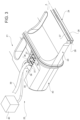
- each vibration control unit 25 may further comprise at least a housing shell 41 (shown in Figure 3 ; the transparent representation is for illustrative reasons) having an inner space 42.
- housing shell 41 is in contact with the respective sonotrode head 23 so as to seal inner space 42 from an outer space.
- each piezoelectric transducer device 35 and each temperature sensor 36 are arranged within the respective inner space 42.
- the respective generator(s) may be arranged within the respective inner space 42.
- each vibration control unit 25 may comprise a coupling portion 43 contacting the respective sonotrode head 23 along a respective contact surface.
- each piezoelectric transducer device 35 may be placed within a respective seat 44 (see in particular Figure 3 ) of the respective coupling portion 43 and in contact with coupling portion 43 so as to allow for the transmission of the generated ultrasonic vibrations into the respective sonotrode head 23.
- packaging machine 1 produces packages 2 filled with the pourable product.
- conveying device 7 advances web 3 along web advancement path P to forming station 8.
- Tube forming and sealing device 10 forms tube 4 from the advancing web 3 and longitudinal seals tube 4.
- filling device 11 fills tube 4 with the pourable product and package forming unit 12 forms, transversally seals and transversally cuts tube 4 so as to obtain packages 2.
- forming and sealing assemblies 19 form, transversally seal, and in particular also transversally cut tube 4 for obtaining respective filled packages 2.
- the forming occurs by means of the respective forming shell, in particular the cooperation of the respective first half-shell and the second half-shell with one another.
- transversal sealing occurs by means of the respective sealing device 20.
- transversal cutting occurs by means of the respective cutting device.
- operation of each sealing device 20 comprises at least the following main steps:
- operation of each sealing device 20 further comprises the steps of:
- each piezoelectric transducer device 35 may be measured by the respective temperature sensor 36 and during the step c) the operating state of each piezoelectric transducer device 35 may be determined in dependence of the respective temperature determined during the respective step b).
- step b) and step c) may be continuously executed.
- each sealing device 20 may further comprise a step of transferring, during which the measurement results of the temperature sensors 36 may be transferred to analysis unit 40 and/or the respective portions of analysis unit 40.
- step c) the remaining life time and/or the aging of piezoelectric transducer(s) 35 may be estimated.
- each sealing device 20 may further comprise d) a step of planning, during which a maintenance is planned based on the operating state of the one or more piezoelectric transducer(s) 35.
- the maintenance can be planned based on the effective remaining life-time and/or aging of piezoelectric transducer(s) 35.
- each sealing device 20 may also comprise a step of alerting, during which the risk of an anomalous working condition may be signaled, e.g. by means of a prompt on a human-machine interface and/or an acoustic message and/or an electronic message of similar.
- sealing device 20 and/or of packaging machine 1 and/or the method according to the present invention will be clear from the foregoing description.
- temperature sensor(s) 36 it is possible to measure the temperature of piezoelectric transducer devices 35 and to monitor and/or determine the operating state of piezoelectric transducer devices 35 in dependence of the measured temperature. In this way, it is possible to monitor on whether piezoelectric transducer devices 35 operate in a correct manner and/or to determine the remaining lifetime and/or the aging of piezoelectric transducers. This again allows to base the decision on whether or not to executed maintenance activities based on the actual aging of piezoelectric transducer devices 35 and not according to a predetermined schedule. This also ensures avoiding undesired failures and unnecessary maintenance activities.
- a further advantage resides in the possibility to obtain real-time data about the operational states of piezoelectric transducer devices 35 allowing to act quickly, thereby, further mitigating the risk of operating anomalies putatively impeding a correct operation of sealing devices 20.
- Another advantage is to connect temperature sensors 36 onto respective metal connectors 38, which are already used for connecting piezoelectric transducer devices 35, in particular piezoelectric elements 37, by means of the respective electric cables 39 to the respective generator(s). In this way, one optimizes the space requirements.
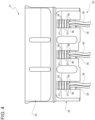
- One or more embodiments may thus relate to a sealing device 20 for sealing packages 2 filled with a pourable product within a packaging machine 1, a portion of which is depicted in figure 5 .
- a sealing device 20 for sealing packages 2 filled with a pourable product within a packaging machine 1 a portion of which is depicted in figure 5 .
- the reference numbers used with reference to figure 5 where corresponding to reference numbers used previously with reference to the remaining figures, have the same meaning and refer to the same features.
- the sealing device 20 has at least one sonotrode 21 comprising at least the sonotrode head 23 and the vibration control unit 25 connected to the sonotrode head 23 and configured to actuate ultrasonic vibrations of the sonotrode head 23.
- the vibration control unit 25 may comprise:
- the temperature sensor 36 may be configured to measure the temperature at the first extremity 39b of an electrical cable 39 that is indicative of the temperature of a respective piezoelectric transducer device 35.
- the temperature at the first extremity of the electrical cable 39 closest to the piezoelectric transducer device 35 is extremely similar to that of the piezoelectric transducer device 35 and, as such, it is possible to obtain an accurate measure of the temperature of the piezoelectric transducer device 35.
- the embodiment depicted in figure 5 might be advantageous insofar as it can be particularly robust in view of the vibrations of the piezoelectric transducer devices 35.
- the one or more temperature sensors 36 may be positioned at the first extremity 39b of the respective one or more electrical cables 39.
- Each electrical cable 39 may comprise electrical wires and a protective sheath 39a surrounding the electrical wires.
- the one or more temperature sensors 36 may be positioned, e.g. at the first extremity 39b, between the protective sheath 39a and the electrical wires of the respective one or more electrical cables 39.
- the one or more temperature sensors 36 may be completely or partially covered by the protective sheath 39a of the respective one or more electrical cables 39.
- the temperature sensor 36 may be pressed onto and/or kept in contact with the electrical wires by means of the sheath 39a.
- the electrical cable (s) 360 providing power to the temperature sensors 36 may be similarly positioned between the protective sheath 39a and the electrical wires of the respective one or more electrical cables 39, e.g. being completely or partially covered by the protective sheath 39a.
- each electrical cable 39 may be connected to at least one generator and, at the first extremity 39b, to at least one metal connector 38 of the piezoelectric transducer devices 35 so as to establish the electrical connection between the generator and metal connector 38.
- the temperature sensor 36 may be configured to measure the temperature at the first extremity 39b, such temperature being indicative of the temperature at the piezoelectric transducer device 35 and at the metal connector 38. This way, in alternative to measuring the temperature of the metal connector 38, it is possible to measure the temperature at the first extremity of the electrical cable 39 and still obtain a reliable, robust and accurate measure of the temperature of the piezoelectric transducer device 35.
- the temperature measure obtained by the temperature sensor 36 at the first extremity 39b of the electrical cable 39 may be thus indicative of the temperature of the respective one or more piezoelectric transducer device 35.
- the analysis unit 40 may be configured to:
- each piezoelectric transducer device 35 has a respective electrical cable 39 that brings power thereto.
- each temperature sensor 26 may be positioned at the extremity 39b of the respective electrical cable 39. That is, each temperature sensor 36 is associated (e.g. in contact or in close proximity) with a single electrical cable 39 and a single piezoelectric transducer device 35.
Landscapes
- Engineering & Computer Science (AREA)
- Mechanical Engineering (AREA)
- Chemical & Material Sciences (AREA)
- Composite Materials (AREA)
- Physics & Mathematics (AREA)
- Thermal Sciences (AREA)
- Package Closures (AREA)
- Lining Or Joining Of Plastics Or The Like (AREA)
- Apparatuses For Generation Of Mechanical Vibrations (AREA)
Claims (17)
- Versiegelungsvorrichtung (20) zum Versiegeln von Verpackungen (2), die mit einem gießbarem Produkt gefüllt werden, innerhalb einer Verpackungsmaschine (1);wobei die Versiegelungsvorrichtung (20) wenigstens eine Sonotrode (21) aufweist, die wenigstens Folgendes umfasst:- einen Sonotrodenkopf (23); und- eine Vibrationssteuereinheit (25), die mit dem Sonotrodenkopf (23) verbunden und zum Auslösen von Ultraschallvibrationen des Sonotrodenkopfes (23) konfiguriert ist;wobei die Vibrationssteuereinheit (25) Folgendes umfasst:- eine oder mehrere piezoelektrische Wandlervorrichtungen (35), die zum Erzeugen von Ultraschallvibrationen konfiguriert sind, die in den Sonotrodenkopf (23) einzukoppeln sind; und- einen oder mehrere Temperatursensoren (36), die zum Messen der Temperatur der einen oder mehreren piezoelektrischen Wandlervorrichtungen (35) zum Bestimmen und/oder Überwachen jeweiliger Betriebszustände der einen oder mehreren piezoelektrischen Wandlervorrichtungen (35) konfiguriert sind,wobei die Vibrationssteuereinheit (25) des Weiteren wenigstens eine Gehäusehülle (41) mit einem Innenraum (42) umfasst;wobei jede piezoelektrische Wandlervorrichtung (35) und jeder Temperatursensor (36) innerhalb des Innenraums (42) angeordnet sind.
- Versiegelungsvorrichtung nach Anspruch 1, wobei der eine oder die mehreren Temperatursensoren (36) mit einer Analyseeinheit (40) wirkgekoppelt und/oder -koppelbar sind, die zum Überwachen und/oder Bestimmen des Betriebszustands der einen oder mehreren piezoelektrischen Wandlervorrichtungen (35) in Abhängigkeit von der Temperatur konfiguriert ist, die durch den einen oder die mehreren Temperatursensoren (36) gemessen wird.
- Versiegelungsvorrichtung nach Anspruch 1 oder 2, wobei wenigstens ein Temperatursensor (36) mit jeder piezoelektrischen Wandlervorrichtung (35) assoziiert ist, so dass die Temperatur der jeweiligen piezoelektrischen Wandlervorrichtung (35) zum Bestimmen und/oder Überwachen des Betriebszustands der jeweiligen piezoelektrischen Wandlervorrichtung (35) gemessen wird.
- Versiegelungsvorrichtung nach Anspruch 3, wobei sich jeder Temperatursensor (36) in Kontakt mit der jeweiligen piezoelektrischen Wandlervorrichtung (35) befindet.
- Versiegelungsvorrichtung nach Anspruch 3 oder 4, wobei jede piezoelektrische Wandlervorrichtung (35) einen Metallverbinder (38) umfasst, der zum Herstellen einer elektrischen Verbindung mit einem Generator der Versiegelungsvorrichtung (20) gestaltet ist;
wobei sich jeder Temperatursensor (36) in Kontakt mit dem Metallverbinder (38) der jeweiligen piezoelektrischen Wandlervorrichtung (35) befindet. - Versiegelungsvorrichtung nach Anspruch 5, wobei der Metallverbinder (38) Kupfer umfasst.
- Versiegelungsvorrichtung nach einem der Ansprüche 1-3, wobei:- die Vibrationssteuereinheit (25) ein oder mehrere elektrische Kabel (39) umfasst, die zum Versorgen der einen oder mehreren jeweiligen piezoelektrischen Wandlervorrichtungen (35) mit Leistung konfiguriert sind, wobei das eine oder die mehreren elektrischen Kabel (39) über einen ersten Endpunkt (39b) der elektrischen Kabel (39) mit einer oder mehreren jeweiligen piezoelektrischen Wandlervorrichtungen (35) verbunden sind, und- der eine oder die mehreren Temperatursensoren (36) zum Messen der Temperatur der einen oder mehreren piezoelektrischen Wandlervorrichtungen (35) durch Messen der Temperatur an dem ersten Endpunkt (39b) des einen oder der mehreren elektrischen Kabel (39) konfiguriert sind.
- Versiegelungsvorrichtung nach Anspruch 7, wobei der eine oder die mehreren Temperatursensoren (36) an dem ersten Endpunkt (39b) des einen oder der mehreren jeweiligen elektrischen Kabel (39) positioniert sind.
- Versiegelungsvorrichtung nach Anspruch 7 oder Anspruch 8, wobei jedes elektrische Kabel (39) elektrische Drähte und eine Schutzumhüllung (39a), die die elektrischen Drähte umgibt, umfasst und wobei der eine oder die mehreren Temperatursensoren (36) zwischen der Schutzumhüllung (39a) und den elektrischen Drähten des einen oder der mehreren jeweiligen elektrischen Kabel (39) positioniert sind.
- Versiegelungsvorrichtung nach einem der vorhergehenden Ansprüche, wobei jeder Temperatursensor (36) ein Thermistor ist.
- Versiegelungsvorrichtung nach Anspruch 10, wobei jeder Temperatursensor (36) ein Thermistor mit negativem Temperaturkoeffizienten oder ein Thermistor mit positivem Temperaturkoeffizienten ist.
- Versiegelungsvorrichtung nach einem der vorhergehenden Ansprüche, wobei ein Betriebszustand der einen oder mehreren piezoelektrischen Wandlervorrichtungen (35) die jeweilige Lebensdauer und/oder die jeweilige Alterung und/oder die Betriebscharakteristiken der einen oder mehreren piezoelektrischen Wandlervorrichtungen (35) ist.
- Verpackungsmaschine (1) für das Verpacken von gießbaren Produkten in Verpackungen (2), welche wenigstens eine Versiegelungsvorrichtung (20) nach einem der Ansprüche 1 bis 12 umfasst.
- Verfahren zum Betreiben einer Versiegelungsvorrichtung (20) nach einem der Ansprüche 1 bis 12, wobei das Verfahren wenigstens die folgenden Schritte umfasst:a) Anregen von Ultraschallvibrationen des Sonotrodenkopfes (23) mittels eines Betriebs der einen oder mehreren piezoelektrischen Wandlervorrichtungen (35);b) Messen der Temperatur der einen oder mehreren piezoelektrischen Wandlervorrichtungen (35); undc) Bestimmen eines Betriebszustands der einen oder mehreren piezoelektrischen Wandlervorrichtungen (35) basierend auf der in Schritt b) erhaltenen Temperatur.
- Verfahren nach Anspruch 14, wobei während des Schrittes b) die Temperatur jeder piezoelektrischen Wandlervorrichtung (35) durch einen jeweiligen Temperatursensor (36) gemessen wird und während des Schrittes c) der Betriebszustand jeder piezoelektrischen Wandlervorrichtung (35) in Abhängigkeit von der jeweiligen Temperatur bestimmt wird, die während des Schrittes b) bestimmt wird.
- Verfahren nach Anspruch 14 oder 15, wobei während des Schrittes c) die verbleibende Lebensdauer und/oder die Alterung der einen oder der mehreren piezoelektrischen Wandlervorrichtungen (35) geschätzt wird.
- Verfahren nach einem der Ansprüche 14 bis 16, das ferner d) einen Schritt zum Planen umfasst, während dessen eine Wartung basierend auf dem Betriebszustand der einen oder der mehreren piezoelektrischen Wandlervorrichtungen (35) geplant wird.
Applications Claiming Priority (1)
| Application Number | Priority Date | Filing Date | Title |
|---|---|---|---|
| EP21167121 | 2021-04-07 |
Publications (2)
| Publication Number | Publication Date |
|---|---|
| EP4070935A1 EP4070935A1 (de) | 2022-10-12 |
| EP4070935B1 true EP4070935B1 (de) | 2025-07-09 |
Family
ID=75426424
Family Applications (1)
| Application Number | Title | Priority Date | Filing Date |
|---|---|---|---|
| EP22166637.3A Active EP4070935B1 (de) | 2021-04-07 | 2022-04-05 | Siegelvorrichtung für eine verpackungsmaschine, verpackungsmaschine mit einer siegelvorrichtung und verfahren zum betrieb einer siegelvorrichtung |
Country Status (5)
| Country | Link |
|---|---|
| US (1) | US12492031B2 (de) |
| EP (1) | EP4070935B1 (de) |
| JP (1) | JP2024514521A (de) |
| CN (1) | CN116723927A (de) |
| WO (1) | WO2022214465A1 (de) |
Family Cites Families (7)
| Publication number | Priority date | Publication date | Assignee | Title |
|---|---|---|---|---|
| JP3135598B2 (ja) * | 1991-04-19 | 2001-02-19 | 株式会社東芝 | 超音波プローブ |
| JPH07265315A (ja) * | 1994-03-31 | 1995-10-17 | Nippon Dempa Kogyo Co Ltd | 超音波探触子 |
| EP2368694A1 (de) * | 2010-03-22 | 2011-09-28 | Tetra Laval Holdings & Finance S.A. | Sonotrode |
| CN202670170U (zh) * | 2011-05-11 | 2013-01-16 | 株式会社石田 | 包装机的横封装置 |
| US8858742B2 (en) * | 2012-11-16 | 2014-10-14 | GM Global Technology Operations LLC | Automatic monitoring of vibration welding equipment |
| JP6553890B2 (ja) | 2015-02-20 | 2019-07-31 | 日本テトラパック株式会社 | 包装充填装置 |
| JP2024540338A (ja) * | 2021-11-19 | 2024-10-31 | テトラ ラバル ホールディングス アンド ファイナンス エス エイ | 包装機用密封装置、密封装置を有する包装機及び密封装置の動作方法 |
-
2022
- 2022-04-05 JP JP2023560866A patent/JP2024514521A/ja active Pending
- 2022-04-05 EP EP22166637.3A patent/EP4070935B1/de active Active
- 2022-04-05 US US18/553,665 patent/US12492031B2/en active Active
- 2022-04-05 WO PCT/EP2022/058964 patent/WO2022214465A1/en not_active Ceased
- 2022-04-05 CN CN202280010562.7A patent/CN116723927A/zh active Pending
Also Published As
| Publication number | Publication date |
|---|---|
| EP4070935A1 (de) | 2022-10-12 |
| WO2022214465A1 (en) | 2022-10-13 |
| CN116723927A (zh) | 2023-09-08 |
| US12492031B2 (en) | 2025-12-09 |
| US20240199260A1 (en) | 2024-06-20 |
| JP2024514521A (ja) | 2024-04-02 |
Similar Documents
| Publication | Publication Date | Title |
|---|---|---|
| US10773846B2 (en) | Anvil for transversally sealing a tube of packaging material and sealing jaw having an anvil | |
| EP1241098B1 (de) | Verfahren und Vorrichtung zum Ultraschallquerversiegeln der Wände eines mit einem fliessfähigen Nahrungsmittel gefüllten Verpackungsmaterials | |
| EP2774746B1 (de) | Sonotrode | |
| JP4093775B2 (ja) | 流動食品を充填された包装材料の壁部をシールする超音波横断シール装置 | |
| JPWO2005028314A1 (ja) | 包装充填装置及び包材切断装置 | |
| EP4070935B1 (de) | Siegelvorrichtung für eine verpackungsmaschine, verpackungsmaschine mit einer siegelvorrichtung und verfahren zum betrieb einer siegelvorrichtung | |
| EP4183559B1 (de) | Siegelvorrichtung für eine verpackungsmaschine, verpackungsmaschine mit einer siegelvorrichtung und verfahren zum betreiben einer siegelvorrichtung | |
| JPWO2005035368A1 (ja) | 包装充填装置及び横シール装置 | |
| CN116249649A (zh) | 用超声波密封设备横向密封包装材料管的方法、砧座和超声波密封设备 | |
| US20250296718A1 (en) | Multilayer rod, sealing unit, package forming apparatus, packaging machine, method for manufacturing a multilater rod and method for manufacturing an induction sealing device | |
| EP4357256A1 (de) | Verpackungsmaschine und verpackungsmaschine zum formen von mit einem fliessfähigen produkt gefüllten verpackungen | |
| JP2009067459A (ja) | 包装充填装置 | |
| EP4410691B1 (de) | Verpackungsmaschine und verpackungsmaschine zum formen von mit einem fliessfähigen produkt gefüllten verpackungen | |
| EP4410524A1 (de) | Verpackungsmaschine und verpackungsmaschine zum formen von mit einem fliessfähigen produkt gefüllten verpackungen | |
| EP4039600A1 (de) | Verpackungsvorrichtung, verfahren zur herstellung von versiegelten verpackungen und verwendung einer tdr-sensorvorrichtung in einer verpackungsvorrichtung | |
| JP2008120435A (ja) | 包装充填装置及び包装充填方法 | |
| JP2017218170A (ja) | 製袋充填包装機 |
Legal Events
| Date | Code | Title | Description |
|---|---|---|---|
| PUAI | Public reference made under article 153(3) epc to a published international application that has entered the european phase |
Free format text: ORIGINAL CODE: 0009012 |
|
| STAA | Information on the status of an ep patent application or granted ep patent |
Free format text: STATUS: THE APPLICATION HAS BEEN PUBLISHED |
|
| AK | Designated contracting states |
Kind code of ref document: A1 Designated state(s): AL AT BE BG CH CY CZ DE DK EE ES FI FR GB GR HR HU IE IS IT LI LT LU LV MC MK MT NL NO PL PT RO RS SE SI SK SM TR |
|
| STAA | Information on the status of an ep patent application or granted ep patent |
Free format text: STATUS: REQUEST FOR EXAMINATION WAS MADE |
|
| 17P | Request for examination filed |
Effective date: 20230412 |
|
| RBV | Designated contracting states (corrected) |
Designated state(s): AL AT BE BG CH CY CZ DE DK EE ES FI FR GB GR HR HU IE IS IT LI LT LU LV MC MK MT NL NO PL PT RO RS SE SI SK SM TR |
|
| GRAP | Despatch of communication of intention to grant a patent |
Free format text: ORIGINAL CODE: EPIDOSNIGR1 |
|
| STAA | Information on the status of an ep patent application or granted ep patent |
Free format text: STATUS: GRANT OF PATENT IS INTENDED |
|
| RIC1 | Information provided on ipc code assigned before grant |
Ipc: B65B 51/30 20060101ALN20250128BHEP Ipc: B65B 51/10 20060101ALN20250128BHEP Ipc: B65B 9/20 20120101ALN20250128BHEP Ipc: B29C 65/78 20060101ALN20250128BHEP Ipc: B06B 3/02 20060101ALI20250128BHEP Ipc: B06B 3/00 20060101ALI20250128BHEP Ipc: B06B 1/06 20060101ALI20250128BHEP Ipc: B65B 51/22 20060101ALI20250128BHEP Ipc: B29C 65/74 20060101ALI20250128BHEP Ipc: B29C 65/08 20060101AFI20250128BHEP |
|
| INTG | Intention to grant announced |
Effective date: 20250210 |
|
| P01 | Opt-out of the competence of the unified patent court (upc) registered |
Free format text: CASE NUMBER: APP_13012/2025 Effective date: 20250317 |
|
| GRAS | Grant fee paid |
Free format text: ORIGINAL CODE: EPIDOSNIGR3 |
|
| GRAA | (expected) grant |
Free format text: ORIGINAL CODE: 0009210 |
|
| STAA | Information on the status of an ep patent application or granted ep patent |
Free format text: STATUS: THE PATENT HAS BEEN GRANTED |
|
| AK | Designated contracting states |
Kind code of ref document: B1 Designated state(s): AL AT BE BG CH CY CZ DE DK EE ES FI FR GB GR HR HU IE IS IT LI LT LU LV MC MK MT NL NO PL PT RO RS SE SI SK SM TR |
|
| REG | Reference to a national code |
Ref country code: GB Ref legal event code: FG4D |
|
| REG | Reference to a national code |
Ref country code: CH Ref legal event code: EP |
|
| REG | Reference to a national code |
Ref country code: IE Ref legal event code: FG4D |
|
| REG | Reference to a national code |
Ref country code: DE Ref legal event code: R096 Ref document number: 602022017171 Country of ref document: DE |
|
| REG | Reference to a national code |
Ref country code: NL Ref legal event code: MP Effective date: 20250709 |
|
| PG25 | Lapsed in a contracting state [announced via postgrant information from national office to epo] |
Ref country code: PT Free format text: LAPSE BECAUSE OF FAILURE TO SUBMIT A TRANSLATION OF THE DESCRIPTION OR TO PAY THE FEE WITHIN THE PRESCRIBED TIME-LIMIT Effective date: 20251110 |
|
| PG25 | Lapsed in a contracting state [announced via postgrant information from national office to epo] |
Ref country code: NL Free format text: LAPSE BECAUSE OF FAILURE TO SUBMIT A TRANSLATION OF THE DESCRIPTION OR TO PAY THE FEE WITHIN THE PRESCRIBED TIME-LIMIT Effective date: 20250709 |
|
| REG | Reference to a national code |
Ref country code: AT Ref legal event code: MK05 Ref document number: 1811485 Country of ref document: AT Kind code of ref document: T Effective date: 20250709 |
|
| PG25 | Lapsed in a contracting state [announced via postgrant information from national office to epo] |
Ref country code: IS Free format text: LAPSE BECAUSE OF FAILURE TO SUBMIT A TRANSLATION OF THE DESCRIPTION OR TO PAY THE FEE WITHIN THE PRESCRIBED TIME-LIMIT Effective date: 20251109 |
|
| PG25 | Lapsed in a contracting state [announced via postgrant information from national office to epo] |
Ref country code: NO Free format text: LAPSE BECAUSE OF FAILURE TO SUBMIT A TRANSLATION OF THE DESCRIPTION OR TO PAY THE FEE WITHIN THE PRESCRIBED TIME-LIMIT Effective date: 20251009 |
|
| REG | Reference to a national code |
Ref country code: LT Ref legal event code: MG9D |
|
| PG25 | Lapsed in a contracting state [announced via postgrant information from national office to epo] |
Ref country code: AT Free format text: LAPSE BECAUSE OF FAILURE TO SUBMIT A TRANSLATION OF THE DESCRIPTION OR TO PAY THE FEE WITHIN THE PRESCRIBED TIME-LIMIT Effective date: 20250709 |
|
| PG25 | Lapsed in a contracting state [announced via postgrant information from national office to epo] |
Ref country code: FI Free format text: LAPSE BECAUSE OF FAILURE TO SUBMIT A TRANSLATION OF THE DESCRIPTION OR TO PAY THE FEE WITHIN THE PRESCRIBED TIME-LIMIT Effective date: 20250709 |
|
| PG25 | Lapsed in a contracting state [announced via postgrant information from national office to epo] |
Ref country code: HR Free format text: LAPSE BECAUSE OF FAILURE TO SUBMIT A TRANSLATION OF THE DESCRIPTION OR TO PAY THE FEE WITHIN THE PRESCRIBED TIME-LIMIT Effective date: 20250709 |
|
| PG25 | Lapsed in a contracting state [announced via postgrant information from national office to epo] |
Ref country code: GR Free format text: LAPSE BECAUSE OF FAILURE TO SUBMIT A TRANSLATION OF THE DESCRIPTION OR TO PAY THE FEE WITHIN THE PRESCRIBED TIME-LIMIT Effective date: 20251010 |
|
| PG25 | Lapsed in a contracting state [announced via postgrant information from national office to epo] |
Ref country code: SE Free format text: LAPSE BECAUSE OF FAILURE TO SUBMIT A TRANSLATION OF THE DESCRIPTION OR TO PAY THE FEE WITHIN THE PRESCRIBED TIME-LIMIT Effective date: 20250709 |
|
| PG25 | Lapsed in a contracting state [announced via postgrant information from national office to epo] |
Ref country code: LV Free format text: LAPSE BECAUSE OF FAILURE TO SUBMIT A TRANSLATION OF THE DESCRIPTION OR TO PAY THE FEE WITHIN THE PRESCRIBED TIME-LIMIT Effective date: 20250709 |
|
| PG25 | Lapsed in a contracting state [announced via postgrant information from national office to epo] |
Ref country code: PL Free format text: LAPSE BECAUSE OF FAILURE TO SUBMIT A TRANSLATION OF THE DESCRIPTION OR TO PAY THE FEE WITHIN THE PRESCRIBED TIME-LIMIT Effective date: 20250709 Ref country code: BG Free format text: LAPSE BECAUSE OF FAILURE TO SUBMIT A TRANSLATION OF THE DESCRIPTION OR TO PAY THE FEE WITHIN THE PRESCRIBED TIME-LIMIT Effective date: 20250709 |
|
| PG25 | Lapsed in a contracting state [announced via postgrant information from national office to epo] |
Ref country code: RS Free format text: LAPSE BECAUSE OF FAILURE TO SUBMIT A TRANSLATION OF THE DESCRIPTION OR TO PAY THE FEE WITHIN THE PRESCRIBED TIME-LIMIT Effective date: 20251009 |
|
| PG25 | Lapsed in a contracting state [announced via postgrant information from national office to epo] |
Ref country code: ES Free format text: LAPSE BECAUSE OF FAILURE TO SUBMIT A TRANSLATION OF THE DESCRIPTION OR TO PAY THE FEE WITHIN THE PRESCRIBED TIME-LIMIT Effective date: 20250709 |
|
| PG25 | Lapsed in a contracting state [announced via postgrant information from national office to epo] |
Ref country code: SM Free format text: LAPSE BECAUSE OF FAILURE TO SUBMIT A TRANSLATION OF THE DESCRIPTION OR TO PAY THE FEE WITHIN THE PRESCRIBED TIME-LIMIT Effective date: 20250709 |
|
| PG25 | Lapsed in a contracting state [announced via postgrant information from national office to epo] |
Ref country code: DK Free format text: LAPSE BECAUSE OF FAILURE TO SUBMIT A TRANSLATION OF THE DESCRIPTION OR TO PAY THE FEE WITHIN THE PRESCRIBED TIME-LIMIT Effective date: 20250709 |
|
| PG25 | Lapsed in a contracting state [announced via postgrant information from national office to epo] |
Ref country code: IT Free format text: LAPSE BECAUSE OF FAILURE TO SUBMIT A TRANSLATION OF THE DESCRIPTION OR TO PAY THE FEE WITHIN THE PRESCRIBED TIME-LIMIT Effective date: 20250709 |
|
| PG25 | Lapsed in a contracting state [announced via postgrant information from national office to epo] |
Ref country code: CZ Free format text: LAPSE BECAUSE OF FAILURE TO SUBMIT A TRANSLATION OF THE DESCRIPTION OR TO PAY THE FEE WITHIN THE PRESCRIBED TIME-LIMIT Effective date: 20250709 |
|
| PG25 | Lapsed in a contracting state [announced via postgrant information from national office to epo] |
Ref country code: SK Free format text: LAPSE BECAUSE OF FAILURE TO SUBMIT A TRANSLATION OF THE DESCRIPTION OR TO PAY THE FEE WITHIN THE PRESCRIBED TIME-LIMIT Effective date: 20250709 Ref country code: EE Free format text: LAPSE BECAUSE OF FAILURE TO SUBMIT A TRANSLATION OF THE DESCRIPTION OR TO PAY THE FEE WITHIN THE PRESCRIBED TIME-LIMIT Effective date: 20250709 |