EP4070932B1 - Blasfolien-coextrusionsanlage mit polygonaler extruderanordnung und entsprechendes verfahren zum coextrudieren - Google Patents
Blasfolien-coextrusionsanlage mit polygonaler extruderanordnung und entsprechendes verfahren zum coextrudieren Download PDFInfo
- Publication number
- EP4070932B1 EP4070932B1 EP22153498.5A EP22153498A EP4070932B1 EP 4070932 B1 EP4070932 B1 EP 4070932B1 EP 22153498 A EP22153498 A EP 22153498A EP 4070932 B1 EP4070932 B1 EP 4070932B1
- Authority
- EP
- European Patent Office
- Prior art keywords
- blown film
- extruder
- film coextrusion
- horizontal
- degrees relative
- Prior art date
- Legal status (The legal status is an assumption and is not a legal conclusion. Google has not performed a legal analysis and makes no representation as to the accuracy of the status listed.)
- Active
Links
Images



Classifications
-
- B—PERFORMING OPERATIONS; TRANSPORTING
- B29—WORKING OF PLASTICS; WORKING OF SUBSTANCES IN A PLASTIC STATE IN GENERAL
- B29C—SHAPING OR JOINING OF PLASTICS; SHAPING OF MATERIAL IN A PLASTIC STATE, NOT OTHERWISE PROVIDED FOR; AFTER-TREATMENT OF THE SHAPED PRODUCTS, e.g. REPAIRING
- B29C48/00—Extrusion moulding, i.e. expressing the moulding material through a die or nozzle which imparts the desired form; Apparatus therefor
- B29C48/03—Extrusion moulding, i.e. expressing the moulding material through a die or nozzle which imparts the desired form; Apparatus therefor characterised by the shape of the extruded material at extrusion
- B29C48/09—Articles with cross-sections having partially or fully enclosed cavities, e.g. pipes or channels
- B29C48/10—Articles with cross-sections having partially or fully enclosed cavities, e.g. pipes or channels flexible, e.g. blown foils
-
- B—PERFORMING OPERATIONS; TRANSPORTING
- B29—WORKING OF PLASTICS; WORKING OF SUBSTANCES IN A PLASTIC STATE IN GENERAL
- B29C—SHAPING OR JOINING OF PLASTICS; SHAPING OF MATERIAL IN A PLASTIC STATE, NOT OTHERWISE PROVIDED FOR; AFTER-TREATMENT OF THE SHAPED PRODUCTS, e.g. REPAIRING
- B29C48/00—Extrusion moulding, i.e. expressing the moulding material through a die or nozzle which imparts the desired form; Apparatus therefor
- B29C48/25—Component parts, details or accessories; Auxiliary operations
- B29C48/266—Means for allowing relative movements between the apparatus parts, e.g. for twisting the extruded article or for moving the die along a surface to be coated
-
- B—PERFORMING OPERATIONS; TRANSPORTING
- B29—WORKING OF PLASTICS; WORKING OF SUBSTANCES IN A PLASTIC STATE IN GENERAL
- B29C—SHAPING OR JOINING OF PLASTICS; SHAPING OF MATERIAL IN A PLASTIC STATE, NOT OTHERWISE PROVIDED FOR; AFTER-TREATMENT OF THE SHAPED PRODUCTS, e.g. REPAIRING
- B29C48/00—Extrusion moulding, i.e. expressing the moulding material through a die or nozzle which imparts the desired form; Apparatus therefor
- B29C48/001—Combinations of extrusion moulding with other shaping operations
- B29C48/0018—Combinations of extrusion moulding with other shaping operations combined with shaping by orienting, stretching or shrinking, e.g. film blowing
-
- B—PERFORMING OPERATIONS; TRANSPORTING
- B29—WORKING OF PLASTICS; WORKING OF SUBSTANCES IN A PLASTIC STATE IN GENERAL
- B29C—SHAPING OR JOINING OF PLASTICS; SHAPING OF MATERIAL IN A PLASTIC STATE, NOT OTHERWISE PROVIDED FOR; AFTER-TREATMENT OF THE SHAPED PRODUCTS, e.g. REPAIRING
- B29C48/00—Extrusion moulding, i.e. expressing the moulding material through a die or nozzle which imparts the desired form; Apparatus therefor
- B29C48/25—Component parts, details or accessories; Auxiliary operations
- B29C48/36—Means for plasticising or homogenising the moulding material or forcing it through the nozzle or die
- B29C48/49—Means for plasticising or homogenising the moulding material or forcing it through the nozzle or die using two or more extruders to feed one die or nozzle
-
- B—PERFORMING OPERATIONS; TRANSPORTING
- B29—WORKING OF PLASTICS; WORKING OF SUBSTANCES IN A PLASTIC STATE IN GENERAL
- B29C—SHAPING OR JOINING OF PLASTICS; SHAPING OF MATERIAL IN A PLASTIC STATE, NOT OTHERWISE PROVIDED FOR; AFTER-TREATMENT OF THE SHAPED PRODUCTS, e.g. REPAIRING
- B29C49/00—Blow-moulding, i.e. blowing a preform or parison to a desired shape within a mould; Apparatus therefor
- B29C49/02—Combined blow-moulding and manufacture of the preform or the parison
- B29C49/04—Extrusion blow-moulding
-
- B—PERFORMING OPERATIONS; TRANSPORTING
- B29—WORKING OF PLASTICS; WORKING OF SUBSTANCES IN A PLASTIC STATE IN GENERAL
- B29C—SHAPING OR JOINING OF PLASTICS; SHAPING OF MATERIAL IN A PLASTIC STATE, NOT OTHERWISE PROVIDED FOR; AFTER-TREATMENT OF THE SHAPED PRODUCTS, e.g. REPAIRING
- B29C2948/00—Indexing scheme relating to extrusion moulding
- B29C2948/92—Measuring, controlling or regulating
- B29C2948/92504—Controlled parameter
- B29C2948/92571—Position, e.g. linear or angular
-
- B—PERFORMING OPERATIONS; TRANSPORTING
- B29—WORKING OF PLASTICS; WORKING OF SUBSTANCES IN A PLASTIC STATE IN GENERAL
- B29C—SHAPING OR JOINING OF PLASTICS; SHAPING OF MATERIAL IN A PLASTIC STATE, NOT OTHERWISE PROVIDED FOR; AFTER-TREATMENT OF THE SHAPED PRODUCTS, e.g. REPAIRING
- B29C2948/00—Indexing scheme relating to extrusion moulding
- B29C2948/92—Measuring, controlling or regulating
- B29C2948/92504—Controlled parameter
- B29C2948/92609—Dimensions
- B29C2948/92638—Length
-
- B—PERFORMING OPERATIONS; TRANSPORTING
- B29—WORKING OF PLASTICS; WORKING OF SUBSTANCES IN A PLASTIC STATE IN GENERAL
- B29C—SHAPING OR JOINING OF PLASTICS; SHAPING OF MATERIAL IN A PLASTIC STATE, NOT OTHERWISE PROVIDED FOR; AFTER-TREATMENT OF THE SHAPED PRODUCTS, e.g. REPAIRING
- B29C2948/00—Indexing scheme relating to extrusion moulding
- B29C2948/92—Measuring, controlling or regulating
- B29C2948/92819—Location or phase of control
- B29C2948/92923—Calibration, after-treatment or cooling zone
-
- B—PERFORMING OPERATIONS; TRANSPORTING
- B29—WORKING OF PLASTICS; WORKING OF SUBSTANCES IN A PLASTIC STATE IN GENERAL
- B29C—SHAPING OR JOINING OF PLASTICS; SHAPING OF MATERIAL IN A PLASTIC STATE, NOT OTHERWISE PROVIDED FOR; AFTER-TREATMENT OF THE SHAPED PRODUCTS, e.g. REPAIRING
- B29C48/00—Extrusion moulding, i.e. expressing the moulding material through a die or nozzle which imparts the desired form; Apparatus therefor
- B29C48/001—Combinations of extrusion moulding with other shaping operations
- B29C48/0019—Combinations of extrusion moulding with other shaping operations combined with shaping by flattening, folding or bending
-
- B—PERFORMING OPERATIONS; TRANSPORTING
- B29—WORKING OF PLASTICS; WORKING OF SUBSTANCES IN A PLASTIC STATE IN GENERAL
- B29C—SHAPING OR JOINING OF PLASTICS; SHAPING OF MATERIAL IN A PLASTIC STATE, NOT OTHERWISE PROVIDED FOR; AFTER-TREATMENT OF THE SHAPED PRODUCTS, e.g. REPAIRING
- B29C48/00—Extrusion moulding, i.e. expressing the moulding material through a die or nozzle which imparts the desired form; Apparatus therefor
- B29C48/16—Articles comprising two or more components, e.g. co-extruded layers
- B29C48/18—Articles comprising two or more components, e.g. co-extruded layers the components being layers
- B29C48/185—Articles comprising two or more components, e.g. co-extruded layers the components being layers comprising six or more components, i.e. each component being counted once for each time it is present, e.g. in a layer
-
- B—PERFORMING OPERATIONS; TRANSPORTING
- B29—WORKING OF PLASTICS; WORKING OF SUBSTANCES IN A PLASTIC STATE IN GENERAL
- B29C—SHAPING OR JOINING OF PLASTICS; SHAPING OF MATERIAL IN A PLASTIC STATE, NOT OTHERWISE PROVIDED FOR; AFTER-TREATMENT OF THE SHAPED PRODUCTS, e.g. REPAIRING
- B29C48/00—Extrusion moulding, i.e. expressing the moulding material through a die or nozzle which imparts the desired form; Apparatus therefor
- B29C48/16—Articles comprising two or more components, e.g. co-extruded layers
- B29C48/18—Articles comprising two or more components, e.g. co-extruded layers the components being layers
- B29C48/21—Articles comprising two or more components, e.g. co-extruded layers the components being layers the layers being joined at their surfaces
-
- B—PERFORMING OPERATIONS; TRANSPORTING
- B29—WORKING OF PLASTICS; WORKING OF SUBSTANCES IN A PLASTIC STATE IN GENERAL
- B29C—SHAPING OR JOINING OF PLASTICS; SHAPING OF MATERIAL IN A PLASTIC STATE, NOT OTHERWISE PROVIDED FOR; AFTER-TREATMENT OF THE SHAPED PRODUCTS, e.g. REPAIRING
- B29C48/00—Extrusion moulding, i.e. expressing the moulding material through a die or nozzle which imparts the desired form; Apparatus therefor
- B29C48/25—Component parts, details or accessories; Auxiliary operations
- B29C48/265—Support structures or bases for apparatus, e.g. frames
-
- B—PERFORMING OPERATIONS; TRANSPORTING
- B29—WORKING OF PLASTICS; WORKING OF SUBSTANCES IN A PLASTIC STATE IN GENERAL
- B29C—SHAPING OR JOINING OF PLASTICS; SHAPING OF MATERIAL IN A PLASTIC STATE, NOT OTHERWISE PROVIDED FOR; AFTER-TREATMENT OF THE SHAPED PRODUCTS, e.g. REPAIRING
- B29C48/00—Extrusion moulding, i.e. expressing the moulding material through a die or nozzle which imparts the desired form; Apparatus therefor
- B29C48/25—Component parts, details or accessories; Auxiliary operations
- B29C48/28—Storing of extruded material, e.g. by winding up or stacking
-
- B—PERFORMING OPERATIONS; TRANSPORTING
- B29—WORKING OF PLASTICS; WORKING OF SUBSTANCES IN A PLASTIC STATE IN GENERAL
- B29C—SHAPING OR JOINING OF PLASTICS; SHAPING OF MATERIAL IN A PLASTIC STATE, NOT OTHERWISE PROVIDED FOR; AFTER-TREATMENT OF THE SHAPED PRODUCTS, e.g. REPAIRING
- B29C48/00—Extrusion moulding, i.e. expressing the moulding material through a die or nozzle which imparts the desired form; Apparatus therefor
- B29C48/25—Component parts, details or accessories; Auxiliary operations
- B29C48/30—Extrusion nozzles or dies
- B29C48/32—Extrusion nozzles or dies with annular openings, e.g. for forming tubular articles
- B29C48/335—Multiple annular extrusion nozzles in coaxial arrangement, e.g. for making multi-layered tubular articles
-
- B—PERFORMING OPERATIONS; TRANSPORTING
- B29—WORKING OF PLASTICS; WORKING OF SUBSTANCES IN A PLASTIC STATE IN GENERAL
- B29C—SHAPING OR JOINING OF PLASTICS; SHAPING OF MATERIAL IN A PLASTIC STATE, NOT OTHERWISE PROVIDED FOR; AFTER-TREATMENT OF THE SHAPED PRODUCTS, e.g. REPAIRING
- B29C48/00—Extrusion moulding, i.e. expressing the moulding material through a die or nozzle which imparts the desired form; Apparatus therefor
- B29C48/25—Component parts, details or accessories; Auxiliary operations
- B29C48/30—Extrusion nozzles or dies
- B29C48/32—Extrusion nozzles or dies with annular openings, e.g. for forming tubular articles
- B29C48/34—Cross-head annular extrusion nozzles, i.e. for simultaneously receiving moulding material and the preform to be coated
-
- B—PERFORMING OPERATIONS; TRANSPORTING
- B29—WORKING OF PLASTICS; WORKING OF SUBSTANCES IN A PLASTIC STATE IN GENERAL
- B29C—SHAPING OR JOINING OF PLASTICS; SHAPING OF MATERIAL IN A PLASTIC STATE, NOT OTHERWISE PROVIDED FOR; AFTER-TREATMENT OF THE SHAPED PRODUCTS, e.g. REPAIRING
- B29C48/00—Extrusion moulding, i.e. expressing the moulding material through a die or nozzle which imparts the desired form; Apparatus therefor
- B29C48/25—Component parts, details or accessories; Auxiliary operations
- B29C48/36—Means for plasticising or homogenising the moulding material or forcing it through the nozzle or die
- B29C48/50—Details of extruders
- B29C48/695—Flow dividers, e.g. breaker plates
- B29C48/70—Flow dividers, e.g. breaker plates comprising means for dividing, distributing and recombining melt flows
- B29C48/71—Flow dividers, e.g. breaker plates comprising means for dividing, distributing and recombining melt flows for layer multiplication
-
- B—PERFORMING OPERATIONS; TRANSPORTING
- B29—WORKING OF PLASTICS; WORKING OF SUBSTANCES IN A PLASTIC STATE IN GENERAL
- B29C—SHAPING OR JOINING OF PLASTICS; SHAPING OF MATERIAL IN A PLASTIC STATE, NOT OTHERWISE PROVIDED FOR; AFTER-TREATMENT OF THE SHAPED PRODUCTS, e.g. REPAIRING
- B29C48/00—Extrusion moulding, i.e. expressing the moulding material through a die or nozzle which imparts the desired form; Apparatus therefor
- B29C48/25—Component parts, details or accessories; Auxiliary operations
- B29C48/92—Measuring, controlling or regulating
-
- B—PERFORMING OPERATIONS; TRANSPORTING
- B29—WORKING OF PLASTICS; WORKING OF SUBSTANCES IN A PLASTIC STATE IN GENERAL
- B29C—SHAPING OR JOINING OF PLASTICS; SHAPING OF MATERIAL IN A PLASTIC STATE, NOT OTHERWISE PROVIDED FOR; AFTER-TREATMENT OF THE SHAPED PRODUCTS, e.g. REPAIRING
- B29C48/00—Extrusion moulding, i.e. expressing the moulding material through a die or nozzle which imparts the desired form; Apparatus therefor
- B29C48/25—Component parts, details or accessories; Auxiliary operations
- B29C48/96—Safety devices
- B29C48/965—Personnel safety, e.g. safety for the operator
-
- B—PERFORMING OPERATIONS; TRANSPORTING
- B29—WORKING OF PLASTICS; WORKING OF SUBSTANCES IN A PLASTIC STATE IN GENERAL
- B29L—INDEXING SCHEME ASSOCIATED WITH SUBCLASS B29C, RELATING TO PARTICULAR ARTICLES
- B29L2007/00—Flat articles, e.g. films or sheets
-
- B—PERFORMING OPERATIONS; TRANSPORTING
- B29—WORKING OF PLASTICS; WORKING OF SUBSTANCES IN A PLASTIC STATE IN GENERAL
- B29L—INDEXING SCHEME ASSOCIATED WITH SUBCLASS B29C, RELATING TO PARTICULAR ARTICLES
- B29L2031/00—Other particular articles
- B29L2031/756—Microarticles, nanoarticles
- B29L2031/7562—Nanoarticles
Definitions
- This present invention is directed to a blown film coextrusion line having an advantageous extruder and die arrangement that provides a sturdy structure and enables a cost saving, compact fit into smaller spaces for transport and use.
- the invention also includes a corresponding method of making a multilayer coextruded blown film.
- Conventional blown film coextrusion lines typically utilize from two to four extruders (sometimes more) that are horizontally disposed and feed into an upward or downward facing blown film coextrusion die and bubble.
- the conventional lines require substantial space and a support structure, sometimes called a "tower,” that contains and stabilizes the coextrusion die, blown film bubble and collapsing nip rollers.
- the extruders are commonly located at or slightly above operator standing level and the blown film bubble travels to collapsing nip rollers that are significantly higher than operator standing level.
- the collapsing nip rollers are closer to operator standing level, however the extruders are significantly higher than operator standing level.
- the support structure must then be large enough and sturdy enough to maintain and stabilize the extruders at an elevated height.
- Each cell includes, in sequence, an end cap disk, a distribution disk, an internal cap disk and a spreader disk (referred to as a spacer disk in the patents).
- a spacer disk in the patents.
- seven cells are stacked on top of each other and another end cap disk is added to enable production of a seven-layer blown film using melt streams that are individually processed into film layers in each of the cells.
- the disks and cells are bolted together to make a single seven-layer die.
- Each of the cells produces one layer of the multilayer film.
- U.S. Patent 11,090,853 B2 and U.S. Patent 11,220,035 B2, both to Schirmer disclose an improved modular disk coextrusion die having an opposing disk arrangement that enables the production of nanolayer films having up to 300 or more layers, using symmetrically arranged cells of thin annular disks that produce two film layers per cell, with each cell being fed at opposing inlet locations that are 180 degrees apart from each other.
- the drawings of each publication illustrate 24-layer nanolayer structures formed using twelve of the cells stacked on top of each other and four extruders, each feeding a different polymer composition. Each cell has two opposed entry points and the twelve-cell die uses twelve polymer entry points to produce 24 nanolayers.
- U.S. Patent 6,413,595 B1 discloses a blown film coextrusion line including at least a first extruder and a second extruder. Each extruder has a proximal end mounted to a support frame and a distal end in fluid communication with a downward facing coextrusion die.
- the patent does not disclose the first and second extruders extending upward from the support frame toward the respective distal ends and does not disclose first and second extruders extending upward at respective first and second angles ranging from 20 to 70 degrees relative to horizontal.
- European Publication EP 1 604 802 A2 discloses an apparatus for manufacturing a strip of rubber compounds comprising four extruders and a single extruder head.
- the extruder head comprises an extruder die assembly and a main body.
- the main body is composed of a pair of laterally-spaced lateral blocks, a central block disposed between the lateral blocks, and a pair of laterally-spaced sub blocks.
- the lateral blocks are each provided with an upper mount face and a lower mount face on which two of the four extruders are respectively attached.
- the publication discloses inclined extruders, but pointing downward instead of upward and refers to the field of rubber extrusion, not blown film coextrusion.
- the present invention is defined by the features of the independent claims 1 and 13.
- the present invention is directed to a blown film coextrusion line that includes a support frame, a plurality of extruders each mounted to the support frame and extending upward at an angle, and a downward facing blown film coextrusion die connected to distal ends of each of the plurality of extruders and receiving individual polymer streams from them.
- the angular arrangement of extruders may resemble a triangle, trapezoid, pyramid or other polygonal or polyhedral shape because the plurality of extruders generally tilt inward, toward each other and toward the blown film coextrusion die.
- the resulting blown film coextrusion line is compact, sturdy, and eliminates much of the floor space and towered mounting structure that was required for conventional blown film coextrusion lines.
- the support frame can include at least four upright support elements, a plurality of lateral support elements each joined to at least two of the upright support elements, and at least one longitudinal support element extending between at least two of the lateral support elements.
- At least a first extruder can be supported by a first of the lateral support elements and can extend upward from the first lateral support element at a first angle.
- At least a second extruder can be supported by a second of the lateral support elements and can extend upward from the second lateral support element at a second angle.
- the first and second angles oppose each other, meaning that the first and second extruders are tilted toward each other so that the distal end of each extruder is in fluid communication with an inlet to the downward facing blown film coextrusion die.
- the first and second angles are 20 to about 70 degrees relative to horizontal, or about 30 to about 60 degrees relative to horizontal, or about 35 to about 55 degrees relative to horizontal, or about 40 to about 50 degrees relative to horizontal, or about 45 degrees relative to horizontal.
- third, fourth, fifth, sixth, seventh, eighth, ninth, tenth, eleventh and/or twelfth extruders can be mounted to the support frame at the same, similar or different angles pointing upward and inward so that the distal end of each and every extruder is in fluid communication with and suitably connected to a corresponding inlet in the downward facing blown film coextrusion die.
- elements of the mounting frame can include a movable platform to which the extruders are mounted, and a mechanism for raising and lowering the movable platform.
- the blown film coextrusion line includes bubble collapsing nip rollers and, suitably, a winding assembly at or near the base of the mounting frame.
- one embodiment of the blown film coextrusion line can include:
- the present invention is also directed to a method of making a multilayer coextruded blown film.
- the method can include the steps of:
- the method can include the steps of:
- the method can include the steps of:
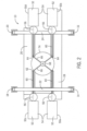
- an exemplary blown film coextrusion line 10 includes a support frame 12 (whose details are shown in Fig. 3 ) that includes at least four upright support elements 14, 16, 18 and 20, a plurality of lateral support elements 22 and 24, and one or more longitudinal support elements 26 and 28.
- Each of the lateral support elements is joined to at least two of the upright support elements.
- a first lateral support element 22 is joined to upright support elements 14 and 18.
- a second lateral support element 24 is joined to upright support elements 16 and 20.
- Each of the longitudinal support elements extends between and is joined to at least two of the lateral support elements.
- longitudinal support elements 26 and 28 extend between and are joined to the first and second lateral support elements 22 and 24.
- the support frame 12 can also include a plurality of mounting pads 30, 32, 34 and 36 which can be connected to the first and second lateral support elements 22 and 24, and can be pivotally connected to the lateral support elements to enable posturing at different angles.
- the support frame 12 can also include one or more elevation mechanisms 38, each of which can include an overhead mounting bar 40 extending between and connected to two of the upright support elements, e.g., 18 and 20, motor driven pulley 42 connected to at least one of the lateral and/or longitudinal support elements , e.g., lateral support element 24, and one or more cables 44 connected to two or more of the lateral and/or longitudinal support elements.
- the lateral and longitudinal support elements 22, 24, 26 and 28 define a movable platform 46 that can be moved vertically relative to the upright support elements 14, 16, 18 and 20.
- the motor driven pulley 42 manipulates the cables 44 to vertically elevate or lower the entire platform 46, as well as the extruders and blown film die that are supported by the platform 46 as described below.
- the structural elements of the support frame 12 are suitably constructed of heavy duty steel, for example, heavy duty stainless steel, so that the support frame 12 is capable of withstanding loads of five to ten tons or more depending on the size and capacity of the blown film coextrusion line 10.
- a suitable support frame is a Tuxedo ® 12,000-lb. Four Post Lift-Cable Driven, sold by SEGA Equipment, LLC.
- extruders 50a, 50b, 50c and 50d are securely mounted to the support frame 12, suitably via mounting pads 30, 32, 34 and 36, which in turn are connected to the first and second lateral support elements 22 and 24 of the support frame 12.
- Each of the extruders can include a drive motor 52 at its proximal end 54, which can be a torque drive motor.
- Advantages of using torque drive motors include lighter weight because no gear box is required, and sufficient power to push the polymer feed uphill at an angle through the extruders.
- Each of the extruders can also include a feed section 56 into which polymer is fed through a hopper 58, an extrusion section 60, and a distal end 62 defining an exit 64.
- Each distal end 62 can be connected to a feed line 66 that is in turn connected to and feeds a respective individual inlet 68 of a downward facing blown film coextrusion die 70.
- the blown film coextrusion die 70 can have as many as twelve separate inlets 68 arranged around the circumference of a thin annular feeding disk as described in the above-identified U.S. Patent 11,090,853 B2 and U.S. Patent 11,220,035 B2 and each of the polymer inlets 68 can ultimately produce several nanolayer film layers having the respective polymer composition.
- the four extruders 50a, 50b, 50c and 50d can be positioned at acute angles relative to horizontal.
- the first extruder 50a is positioned at a first angle and the second extruder 50b is positioned at a second angle, with the first end second angles opposing each other.
- the third extruder 50c is positioned at a third angle which can also oppose the second angle.
- the fourth extruder 50d is positioned at a fourth angle that opposes the third angle and can also oppose the first angle.
- the phrases "opposing angles” and "angles that oppose each other” mean that the subject extruders are tilted toward each other, for example in a triangular or trapezoidal configuration.
- the first, second, third and fourth angles can each be about 20 to about 70 degrees from horizontal, or about 30 to about 60 degrees from horizontal, or about 35 to about 55 degrees from horizontal, or about 40 to about 50 degrees from horizontal, or about 45 degrees from horizontal as shown.
- the opposing first and third angles can be of the same magnitude, but in some cases may have different magnitudes.
- the opposing second and fourth angles may be of the same magnitude, but in some cases may have different magnitudes.
- the blown film coextrusion line 10 can include fifth, sixth, seventh, eighth, ninth, tenth, eleventh and/or twelfth extruders that can be mounted on opposite sides of the support frame 12 in similar opposing fashion as the extruders 50a, 50b, 50c and 50d at angles within the ranges described above, with the extruders on the opposite sides being mounted at angles that oppose each other.
- This enables the distal end 62 of each extruder to feed polymer into the blown film coextrusion die 70 while the proximal end 54 of each extruder can be positioned on or below the opposing first and second lateral support elements 22 and 24 of the support frame 12.
- the blown film coextrusion die 70 includes an end plate 72 resting above an air ring 74 which is sized so that it can be connected to and supported by engaging portions of the extruders 50a, 50b, 50c and 50d.
- the blown film coextrusion die 70 is also supported by the hanging connections provided by the feed lines 66 extending from the four extruders.
- the blown film coextrusion die 70 By surrounding and sandwiching the blown film coextrusion die 70 between the extruders 50a, 50b, 50c and 50d, the feed lines 66 and the appropriately sized air ring 74, the blown film coextrusion die 70 can be maintained in a stable position during operation without requiring the use of a tower as used in conventional blown film coextrusion lines.
- the blown film coextrusion die 70 thus produces a stable bubble 76 that can be ultimately collapsed upon entering collapsing frame 78, passed between nip rollers 80 located at or near the base 82 of support frame 12, and wound and stored as a flat film.
- the downward facing blown film coextrusion die 70 can have a variety of die configurations provided they are sufficiently compact to fit within the limited available space.
- Suitable die configurations include without limitation known modular disk coextrusion die configurations, including without limitation modular disk coextrusion dies with opposing disk arrangements described in U.S. Patent 11,090,853 B2 and U.S. Patent 11,220,035 B2, both issued to Schirmer .
- These and other modular disk coextrusion dies employ suitable arrangements of thin annular disks to produce a variety of complex and more simple blown film structures, including nanolayer blown film structures having unique barrier properties and other physical characteristics.
- the foregoing modular disk coextrusion dies can comfortably accommodate up to twelve polymer entry points that can be used to form repeating and/or alternating layer arrangements having up to twelve different polymer compositions.
- By extruding the bubble 76 downward it is possible to add a liquid through the die 70 that forms a reservoir above the nip rolls 80,creating a hydrostatic pressure that can reduce or eliminate edge wrinkles.
- the space below the air cooling ring 70 is sufficiently large to add secondary air cooling rings (not shown) to enable coextrusion at higher rates.
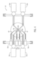
- Fig. 4 is a schematic top view of an alternative blown film coextrusion line 10 that includes additional extruders.
- two smaller satellite extruders 50e and 50f are mounted on both sides of the extruder 50a and two smaller satellite extruders 50g and 50h are mounted on both sides of the extruder 50b.
- the satellite extruders 50e and 50f feed individual polymer streams into two individual feed lines 67 that can ultimately approach the feed line 66 associated with extruder 50a.
- the polymer compositions from extruders 50a, 50e and 50f can thus be fed into three separate inlets 68 of coextrusion dies 70 to make three individual film layers.
- the satellite extruders 50g and 50h feed individual polymer streams into two individual feed lines 69 that can ultimately approach the feed line 66 associated with extruder 50b.
- the polymer compositions from extruders 50b, 50g and 50h can thus be fed into three separate inlets 68 of coextrusion dies 70 to make three individual film layers.
- two smaller satellite extruders can be placed adjacent to all four extruders 50a, 50b, 50c and 50d to enable the feeding of twelve different polymer streams into the blown film coextrusion die 70, thus enabling the production of a wide variety of nanolayer film structures ranging from complex to simple as described in U.S. Patent 11,090,853 B2 and U.S. Patent 11,220,035 B2 , for example.
- the first, second, third and fourth extruders 50a, 50b, 50c and 50d each can have an extruder screw diameter of about 20 mm to about 100 mm, or about 25 mm to about 75 mm, or about 40 mm to about 60 mm, or about 50 mm. These four extruders may each have the same screw diameter or may have different screw diameters. When fifth, sixth, seventh and eighth extruders 50e, 50f, 50g and 50h are utilized, they may have the same or different diameters than the extruders 50a, 50b, 50c and 50d.
- the fifth, sixth, seventh and eighth extruders can have smaller diameters that the first, second, third and fourth extruders.
- the first, second, third and fourth extruders 50a, 50b, 50c and 50d may each have an extrusion screw diameter of about 50 mm.
- the fifth, sixth, seventh and eighth extruders 50e, 50f, 50g and 50h may each have a smaller extrusion screw diameter of about 25 mm.
- Additional extruders can also be included in the blown film coextrusion line 10 as needed for a particular application.
- tilting the extruders upward at shown in Fig, 1 for example, removal and cleaning of the extrusion screws from the extruders becomes easier due to the assistance from gravity. It also becomes easier to perform maintenance at close to ground level, and to fill the extruder hoppers 58 with polymer pellets or powder.
- the tilting also virtually guarantees that the extruders will be fully loaded while feeding molten polymer to the blown film coextrusion die 70, helping to assure consistent and reliable polymer feed rates.
- a mezzanine is no longer needed because all die and air ring adjustment can be performed at close to ground level by lowering the blown film coextrusion die to its lowest position as shown in Fig, 5 and described further below.
- the upward tilt enables the use of a torque direct drive motor in each extruder, which is easier to remove and replace when the extrusion screws are removed for cleaning.
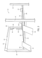
- Fig. 5 schematically illustrates how the adjustable platform 46 described above can be used to raise and lower the extruders 50a, 50b, 50c, 50d, etc. (collectively "50"), and the blown film coextrusion die 70 to three different vertical positions in the blown film coextrusion line 10.
- the extruders 50 and die 70 are located furthest from the base 82, resulting in a relatively long blown film bubble 76 that may be suitable for higher production rates and/or polymer compositions that are more difficult to quench, thus warranting longer cooling distances.
- the extruders 50 and die 70 are located midway above the base 82, resulting in a blown film bubble of intermediate length that may be suitable for intermediate production rates and/or polymer compositions that are relatively easier to quench when present in film layers.
- the extruders 50 and die 70 are located relatively close to the base 82, resulting in a short blown film bubble that may be suitable for lower production rates and/or polymer compositions that quench very quickly when present in film layers.
- the position 10c is also useful for cleaning, maintaining, adjusting, and repairing the blown film coextrusion line 10 because the primary operating components are at or near the standing level of an operator.
- the extruders 50 should have a suitable length and size to a) achieve the desired blown film production rates and b) extend an appropriate distance from the platform 46 to the coextrusion die 70 to provide the desired support for the die 70 and enable the formation of a triangular or other desired polygonal or polyhedral arrangement so as to alleviate the need for a tower or similar structure.
- the primary extruders 50a, 50b, 50c and 50d can be 2-inch extruders made and sold by Davis-Standard, LLC and the satellite extruders can be somewhat smaller as needed to meet space limitations.
- the blown film coextrusion die 70 can be of suitable size to produce a 40-inch wide film at a production rate of 300 lbs./hr. Other sizes and dimensions of the extruders, coextrusion die and related components can also be selected as needed to provide coextruded blown films having a wide variety of sizes at a variety of production rates.
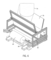
- the collapsing frame 78 and nip rollers 80 may form part of a rotating converging frame winder 100 that, in one embodiment, can exhibit continuous 360-degree rotation while collapsing the downward facing coextruded blown film bubble 76 for winding around a roller 84.
- the winder 100 includes the collapsing frame 78, the nip rollers 80, the frame 82 and the winding roller 84 mounted to a rotating turntable that includes a circular mount 86, a gear assembly 88 driven by a motor 89, and an axle assembly 90 including an axle 92, rotational slide bearings 94 and a mounting shaft 95.
- the gear assembly 88 engages an inner surface of the circular mount 86 as shown in Fig. 7 .
- the resulting rotation of the circular mount 86 around the axle shaft 92 aided by rotational slide bearings 94, causes a continuous 360-degree rotation of the circular mount 86 and the associated collapsing frame 78, nip rollers 80, frame 82 and winding roller 84 as the coextruded blown film bubble 76 is being generated.
- the continuous rotation helps to eliminate nonuniformities such as edge lines, die lines and thickness variations in the collapsed blown film, resulting in a more uniform higher quality coextruded multilayer blown film.
- the entire converging frame winder 100 and all of its components can be mounted to and supported by a stationary support frame 96 that includes a plurality of interconnected and/or interlocking support beams 98 as shown in Fig. 7 .
- the mounting shaft 95 of the axle assembly 90 penetrates and is supported by one of the support beams 98, while the motor 89 and gear assembly 88 are mounted to and supported by another of the support beams 98.
- the motor 89 can be a Dayton 1 ⁇ 2 hp variable speed drive motor.
- the motor 89 can be affixed to the rotating circular mount 86, also called a turntable, using a driven rubber wheel (gear assembly 88) to facilitate the 360-degree rotation.
- the 360-degree rotation enables production of finished blown film rolls having a flat profile because any thickness variations are evenly scattered across the width of the collapsed, flattened coextruded blown film.
- the corresponding method of making a multilayer coextruded blown film can be used to make a wide variety of coextruded blown films and is particularly suited for making simple or complex nanolayer blown films as described in U.S. Patent Publication 11,220,035 B2 .
- the coextrusion die 70 can be a modular disk coextrusion die having an opposing disk arrangement as described in the foregoing publication.
- a multilayer nanolayer blown film is understood to mean films that are composed primarily of nanolayers having thicknesses of less than about 0.001 mm (less than about 1000 nm), or about 1 to about 999 nm.
- the nanolayer film may include at least about 80% nanolayers based on the total number of film layers, or at least about 90% nanolayers, or at least about 95% nanolayers, or at least about 99% nanolayers, or about 100% nanolayers.
- the multilayer nanolayer film may have at least about 25 nanolayers, or at least about 50 nanolayers, or at least about 75 nanolayers, or at least about 100 nanolayers, or at least about 150 nanolayers, or at least about 200 nanolayers, or at least about 250 nanolayers, or at least about 300 nanolayers.
- the multilayer nanolayer film can include up to about 1000 nanolayers, or up to about 800 nanolayers, or up to about 600 nanolayers, or up to about 500 nanolayers, or up to about 400 nanolayers, or up to about 300 nanolayers.
- the multilayer nanolayer blown film can utilize up at about 12, or up to about 16, or up to about 20, or up to about 24 polymer melt streams provided using an appropriate number of extruders.
- the melt streams can have the same, different, and/or a combination of the same and different polymer compositions.
- the blown film coextrusion line 10 enables the production of a wide variety of complex multilayer coextruded annular films, each including many continuous unbroken and non-overlapping annular nanolayers arranged in sequence.
- continuous, unbroken and non-overlapping means that each of the nanolayers and the overall film is a) continuous in the annular direction, b) devoid of breaks and discontinuities in the annular direction, and c) devoid of overlapping folds, i.e., no annular portion of any nanolayer or the overall film is folded over onto itself in a manner that would multiply the film thickness at that location.
- the blown film coextrusion line 10 can be used to produce nanolayer films having large numbers of nanolayers and exhibiting high levels of transparency and/or thermoformability.
- Barrier films containing various layer combinations of polyethylene terephthalate glycol (PETG) ethylene acrylic acid (EAA), low-density or linear low density polyethylene (LDPE or LLDPE) and ethylene-vinyl alcohol (EVOH) have been found to exhibit excellent transparency and thermoformability.
- Similar film combinations made using nylon-6 instead of or in addition to EVOH exhibit high transparency as well as thermoformability at tailored layer thicknesses.
- Other polyester homopolymers and copolymers can also be used in place of or in addition to the PETG.
- Exemplary polyester homopolymers include without limitation polyethylene terephthalate, polybutylene terephthalate, and combinations thereof. Polyester homopolymers provide excellent transparency but are generally not heat sealable. In order to provide the nanolayer film with heat sealability, one or both of the outer layers can be formed using a polyester copolymer. Suitable polyester copolymers include without limitation polyethylene terephthalate glycol, polyethylene terephthalate -1,4-cyclohexane-2 methyl ester, polyester-polyether block copolymers, and combinations thereof. Polyethylene terephthalate glycol (PETG) is particularly suitable for one or both outer film layers because it provides excellent heat sealability and transparency. For optimal transparency, the polyester copolymer can have a degree of crystallinity of less than about 20%, suitably less than about 15%, measured using ASTM D1505.
- nanolayers of the films can be as thin as possible in order to provide the multilayer coextruded nanolayer films 10 with maximum transparency.
- the term "nanolayers" refers to film layers having thicknesses in the submicron range, typically between about 1 to about 999 nanometers, or about 10 to about 500 nanometers, or about 20 to about 100 nanometers.
- Film clarity is a measure of percent light transmittance and can be measured using ASTM D1746. For example, when a film is exposed to 100% of an incident light source, the transmittance is 100% minus (percent absorption + percent reflection).
- the multilayer coextruded nanolayer film produced using the modular disk coextrusion die 10 can have a light transmittance of at least about 80%, suitably at least about 84%, or at least about 88%.
- the multilayer coextruded nanolayer film can also include adhesive tie nanolayers that bond the remaining nanolayers together and exhibit adhesive bonding both to moisture barrier nanolayers (for example, LDPE or LLDPE) and oxygen barrier nanolayers (for example, EVOH or polyamide) in order to bond them together.
- the adhesive tie layers can be formed of a soft polymer that exhibits tackiness without compromising film clarity. Suitable soft polymers include without limitation ethylene methyl acrylate (EMA), ethylene ethyl acrylate (EEA), ethylene acrylic acid (EAA), ethylene methacrylic acid (EMMA), and combinations thereof. EEA and EAA are particularly suitable as nanolayer tie layers that provide excellent adhesion and transparency because of their low crystallinity and high clarity.
- the foregoing adhesives can also be blended with other adhesive materials, such as chemically-modified polyolefins, provided that the desired clarity can be maintained.
- Suitable chemically-modified polyolefins include without limitation anhydride-modified polyethylenes, including low density or linear low density polyethylene grafted with maleic anhydride.
- the chemically-modified polyolefin can improve the adhesion between the polar oxygen barrier layers (for example, EVOH or polyamide) and the moisture barrier layers (for example, LDPE or LLDPE) and can also bond well to the PETG or other polyester copolymer used for outer heat seal layers.
- the adhesive tie layers can suitably be nanolayers having only the thickness needed to ensure adequate bonding between adjacent layers.
- the LDPE or LLDPE nanolayers can be selected to have relatively low crystallinity in order to maintain optimal transparency.
- Nanolayers formed using low density polyethylene or linear low density polyethylene can be selected to have a crystallinity at the lower end of the conventional range for optimal clarity.
- Low density and linear low density polyethylene typically have crystallinities ranging from about 35% to about 60%.
- the low density or linear low density polyethylene can be selected to have a crystallinity at the lower end of the normal range, suitably about 35% to about 45%, or about 35% to about 40%, and can have a density of about 0.910 to about 0.925 grams/cm 3 .
- the blown film coextrusion line 10 and the corresponding method of the invention can be used to produce a wide variety of simple and complex blown (annular) film structures, including without limitation the multilayer nanolayer films described above and below.
- the blown film line 10 and corresponding method can be used to produce complex blown (annular) films in which any sequence of nanolayers formed using up to twelve, sixteen, twenty or twenty-four polymer melt streams can be optimized to provide optimal combinations of oxygen barrier, moisture barrier, strength and/or other desired properties. Large sequences of layers called "repeating units" can be included in the nanolayer films and can be repeated many times.
- the multilayer coextruded annular film including the plurality of continuous unbroken and overlapping nanolayers can include a number "x" of repeating units that define a repeating sequence of nanolayers.
- Each repeating unit includes a number "y" of nanolayers and includes at least three layers having polymer compositions that differ from each other.
- the number "x" is an integer of at least 2, or at least 3, or at least 4, or at least 5, or at least 6, or at least 7, or at least 8, or at least 9, or at least 10, or at least 11, or at least 12.
- the number "y” is an integer of at least 3, or at least 4, or at least 5, or at least 6, or at least 7, or at least 8, or at least 9, or at least 10, or at least 11, or at least 12.
- the product of x multiplied by y is at least 24, or at least 36, or at least 48, or at least 60, or at least 72, or at least 84, or at least 96, or at least 108, or at least 120, or at least 132, or at least 144, or at least 156, or at least 168, or at least 180, or at least 192, or at least 204.
- at least three, or at least four, or at least five, or at least six, or at least seven, or at least eight, or at least nine, or at least ten, or at least eleven, or at least twelve of the nanolayers in the repeating unit have polymer compositions that differ from each other.
- x is at least 64 and “y” is at least 3. In another embodiment, “x” is at least 48 and “y” is at least 4.
- the foregoing embodiments are exemplary and non-limiting. And combination of “x,” “y” and the product of “x” and “y” is contemplated, so long as “x” is at least 2, “y” is at least 3, and the product of "x” and “y” is at least 24.
- the nanolayer film structures that can be produced using the blown film coextrusion line 10 can include a wide variety of polymer combinations designed to optimize properties such as oxygen barrier, moisture barrier, adhesion between layers, film strength and optics.
- oxygen barrier polymers include without limitation polyamides, ethylene vinyl alcohols, polyketones, polyvinyl chlorides, copolymers of vinyl chloride and methyl acrylate, copolymers of vinyl chloride and ethyl acrylate, and combinations thereof.
- Polyamides include without limitation Nylon 6, Nylon 4-6, Nylon 6-6, Nylon 6-9, Nylon 6-10, Nylon 6-12, Nylon 11, and Nylon 12.
- Ethylene vinyl alcohol includes copolymers of ethylene and vinyl alcohol having ethylene contents ranging from about 25% to about 50% by mol, including without limitation those having molar ethylene contents of 27%, 29%, 32%, 38%, 44% and 48%.
- Polyketones are copolymers and terpolymers of olefins and carbon monoxide, including without limitation ethylene-carbon monoxide, propylene-carbon monoxide, ethylene-propylene-carbon monoxide, and the like.
- Polyketones and polyvinyl chlorides provide both oxygen barrier and moisture barrier, unlike many gas barrier polymers that provide oxygen barrier but little or no moisture barrier.
- Moisture barrier polymers include without limitation polyolefins such as polyethylene, polypropylene, polybutene, ethylene-alpha olefin copolymers; polyvinyl chlorides (especially polyvinyl dichloride); and polyketones.
- Polyethylenes include high density polyethylene and branched low density polyethylene.
- Ethylene-alpha olefin copolymers are copolymers of ethylene and one or more comonomers selected from C 3 to C 10 alpha-olefins. Examples include linear medium density polyethylene, linear low density polyethylene, very low density polyethylene and ultra-low density polyethylene.
- the most common comonomers are propylene, butene, hexene and octene. The density generally decreases as the amount of comonomer is increased.
- Adhesive tie resins are typically needed to bond oxygen barrier and moisture barrier layers together, and/or to bond both oxygen barrier and moisture barrier layers to the high strength polymer layers described below.
- Adhesive tie resins include without limitation ethylene vinyl acetate, ethylene methyl acrylate, ethylene ethyl acrylate, ethylene methyl methacrylate, ethylene acrylic acid, ethylene methacrylic acid, anhydride-modified polyolefins such as polyethylene, polypropylene and polybutene, anhydride-modified ethylene-alpha olefin copolymers, and ionomers.
- Elastomers such as styrene-butadiene, styrene-butadiene-styrene, styrene-ethylene-butadiene-styrene, and polycaprolactones can also be used alone or in combination with other adhesive tie polymers to provide enhanced adhesion between adjacent layers.
- High strength polymers can be employed to provide enhanced film strength, abuse resistance and, in some cases, improved optical properties.
- High strength polymers include without limitation polyesters such as polyethylene terephthalate, polybutylene terephthalate, polyethylene terephthalate-1,4-cyclohexane-2-methyl ester, polycarbonate, polycyclohexylene-dimethylene terephthalate, polyphthlate carbonate, polytrimethylene terephthalate; polycarbonates; polystyrenes; polyvinyl chlorides; polyacrylonitrile; and styrene acrylonitrile.
- the blown film coextrusion line 10 can produce multilayer coextruded annular films, such as nanolayer films, having continuous unbroken and non-overlapping nanolayers in the circumferential (annular) direction.
- multilayer coextruded annular films that possess the continuous unbroken and non-overlapping nanolayers include films having any of the foregoing combinations of "x" and "y" in the repeating units, and including, but not limited to, the following examples:
- Embodiments of the method of making a multilayer coextruded blown film using the blown film coextrusion line can include the following steps.
- the method can include the steps of:
- the method can include the following further steps:
- the method can include the following further steps:
- the method can include the following further steps:
- the first, second and third angles can be acute angles relative to horizontal, meaning they are greater than zero and less than 90 degrees from horizontal.
- the first, second and third angles can each be about 20 to about 70 degrees from horizontal, or about 30 to about 60 degrees from horizontal, or about 35 to about 55 degrees from horizontal, or about 40 to about 50 degrees from horizontal, or about 45 degrees from horizontal.
- angle is an "acute angle" if an angle of greater than zero and less than 90 degrees can be measured any direction, so long as the forward ends of the extruders and corresponding directions of extrusion of the polymer melt streams point directly or indirectly toward each other instead of away from each other.
- all four extruders 50a, 50b, 50c and 50d are deemed to point directly or indirectly toward another extruder and each extruder and direction of extrusion forms an acute angle of about 45 degrees from horizontal.
- Extruders 50a and 50b point toward each other.
- Extruders 50c and 50d point directly toward each other.
- Extruders 50a and 50d point indirectly toward each other.
- Extruders 50b and 50c point indirectly toward each other.
- each additional polymer melt stream and corresponding extruder should point directly or indirectly to at least one, preferably more than one other extruder and polymer melt stream and should form corresponding fourth, fifth, sixth and, if applicable, additional acute angles relative to horizontal.
- the fourth, fifth, sixth and, to the extent applicable additional angles can each be about 20 to about 70 degrees from horizontal, or about 30 to about 60 degrees from horizontal, or about 35 to about 55 degrees from horizontal, or about 40 to about 50 degrees from horizontal, or about 45 degrees from horizontal, for example.
- first, second and third angles can be acute angles that are about equal to each other.
- fourth, fifth, sixth and any additional angles can be about equal to each other and about equal to the first, second and third angles.
- the method can further include the step of a) raising the first, second and third extruders and, when present, fourth, fifth, sixth and additional extruders, and the blown film coextrusion die, suitably in tandem, to increase a length of the blown film coextrusion bubble 76.
- the method can further include the step b) of lowering the first, second and third extruders and, when present, fourth, fifth, sixth and additional extruders, and the blown film coextrusion die, suitably in tandem, to decrease a length of the blown film coextrusion bubble 76.
- Optimization of the blown film coextrusion bubble 76 may include increasing and decreasing the bubble length multiple times until optimum bubble properties are achieved.
- a stiffer coextruded film justifying a shorter bubble length and height is a coextruded barrier film made from PETG, modified polyethylene adhesive, EVOH and LLDPE, suitably in that order of layers.
- the PETG has a relatively high glass transition temperature of about 85°C. Therefore, it is desirable to keep the bubble above the glass transition temperature of the PETG through the collapsing stage, where the film is softer and can be collapsed without creating wrinkles. Yet the bubble must be cool enough so that the coextruded film does not stick to itself when passing through the nip rollers and winding. Optimization can therefore be accomplished by raising and lowering the bubble length and height until the best conditions are achieved.
- Polycarbonate is another very stiff material with a high glass transition temperature, warranting a hot bubble with a short bubble length to avoid wrinkles during collapsing and convergence.
- a softer coextruded film justifying a longer bubble length, height and colling time is a barrier film formed using LLDPE, modified polyethylene adhesive, and EVOH, suitably in that order of layers.
- This layer combination includes all crystalline materials with relatively low glass transition temperatures.
- the layer combination remains relatively soft as the bubble is cooled using the air ring, and a long bubble length and cooling time do not cause wrinkles during collapsing and convergence of the coextruded blown film bubble.
- the bubble length needed for most soft materials is the length needed to cool and quench the coextruded blown film.
- the method can further include the steps of collapsing the downward facing coextruded blown film bubble and winding the coextruded blown film bubble.
- these steps can be performed using the rotating converging frame winder described above.
Landscapes
- Engineering & Computer Science (AREA)
- Mechanical Engineering (AREA)
- Manufacturing & Machinery (AREA)
- Extrusion Moulding Of Plastics Or The Like (AREA)
- Laminated Bodies (AREA)
Claims (14)
- Blasfolien-Coextrusionsanlage, umfassend:einen Trägerrahmen;mindestens einen ersten Extruder mit einem ersten proximalen Ende und einem ersten distalen Ende, wobei das erste proximale Ende am Trägerrahmen montiert ist, wobei sich der erste Extruder vom Trägerrahmen nach oben in Richtung des ersten distalen Endes in einem ersten Winkel erstreckt;mindestens einen zweiten Extruder mit einem zweiten proximalen Ende und einem zweiten distalen Ende, wobei das zweite proximale Ende am Trägerrahmen montiert ist, wobei sich der zweite Extruder vom Trägerrahmen nach oben in Richtung des zweiten distalen Endes in einem zweiten Winkel erstreckt; undeine nach unten gerichtete Blasfolien-Coextrusionsdüse in Fluidverbindung mit dem ersten distalen Ende des ersten Extruders und dem zweiten distalen Ende des zweiten Extruders;wobei der erste Winkel 20 bis 70 Grad relativ zur Horizontalen beträgt, der zweite Winkel 20 bis 70 Grad relativ zur Horizontalen beträgt und der erste und der zweite Winkel einander entgegengesetzt sind.
- Blasfolien-Coextrusionsanlage nach Anspruch 1, wobei der erste und der zweite Winkel jeweils 30 bis 60 Grad relativ zur Horizontalen oder 35 bis 55 Grad relativ zur Horizontalen oder 40 bis 50 Grad relativ zur Horizontalen betragen.
- Blasfolien-Coextrusionsanlage nach Anspruch 1 oder 2, ferner umfassend einen dritten Extruder, der am Trägerrahmen montiert ist und sich vom Trägerrahmen nach oben in einem dritten Winkel erstreckt;wobei die nach unten gerichtete Blasfolien-Coextrusionsdüse in Fluidverbindung mit einem dritten distalen Ende des dritten Extruders steht;wobei der dritte Winkel 20 bis 70 Grad relativ zur Horizontalen oder 30 bis 60 Grad relativ zur Horizontalen oder 35 bis 55 Grad relativ zur Horizontalen oder 40 bis 50 Grad relativ zur Horizontalen beträgt.
- Blasfolien-Coextrusionsanlage nach Anspruch 3, ferner umfassend einen vierten Extruder, der am Trägerrahmen montiert ist und sich vom Trägerrahmen nach oben in einem vierten Winkel erstreckt;wobei die nach unten gerichtete Blasfolien-Coextrusionsdüse in Fluidverbindung mit einem vierten distalen Ende des vierten Extruders steht;wobei der vierte Winkel 20 bis 70 Grad relativ zur Horizontalen oder 30 bis 60 Grad relativ zur Horizontalen oder 35 bis 55 Grad relativ zur Horizontalen oder 40 bis 50 Grad relativ zur Horizontalen beträgt.
- Blasfolien-Coextrusionsanlage nach einem der Ansprüche 1 bis 4, wobei der Trägerrahmen ferner eine bewegliche Plattform zum Anheben und Absenken des ersten und zweiten Extruders und der nach unten gerichteten Blasfolien-Coextrusionsdüse umfasst.
- Blasfolien-Coextrusionsanlage nach einem der Ansprüche 1 bis 5, wobei die nach unten gerichtete Blasfolien-Coextrusionsdüse mit dem ersten distalen Ende des ersten Extruders und dem zweiten distalen Ende des zweiten Extruders verbunden ist.
- Blasfolien-Coextrusionsanlage nach einem der Ansprüche 1 bis 6, ferner umfassend eine Wickleranordnung an oder in der Nähe einer Basis des Montagerahmens.
- Blasfolien-Coextrusionsanlage nach einem der Ansprüche 1 bis 7, wobei:der Trägerrahmen mindestens vier aufrechte Trägerelemente, eine Vielzahl von seitlichen Trägerelementen, die jeweils mit mindestens zwei der aufrechten Trägerelemente zusammengefügt sind, und mindestens ein längs verlaufendes Trägerelement beinhaltet, das sich zwischen mindestens zwei der seitlichen Trägerelemente erstreckt;mindestens der erste Extruder von einem ersten der seitlichen Trägerelemente getragen wird und sich vom ersten der seitlichen Trägerelemente im ersten Winkel nach oben erstreckt; undmindestens der zweite Extruder von einem zweiten der seitlichen Trägerelemente getragen wird und sich vom zweiten der seitlichen Trägerelemente im zweiten Winkel nach oben erstreckt.
- Blasfolien-Coextrusionsanlage nach Anspruch 8, wobei die seitlichen und längs verlaufenden Trägerelemente eine bewegliche Plattform definieren, die relativ zu den aufrechten Trägerelementen vertikal bewegt werden kann.
- Blasfolien-Coextrusionsanlage nach Anspruch 8, umfassend:mindestens vier der Extruder, die an der Vielzahl von seitlichen Trägerelementen montiert sind, wobei sich mindestens ein erster und ein dritter der vier Extruder von einem ersten der seitlichen Trägerelemente in einem ersten bzw. dritten Winkel nach oben erstrecken und sich mindestens ein zweiter und ein vierter der vier Extruder von einem zweiten der seitlichen Trägerelemente in einem zweiten bzw. vierten Winkel nach oben erstrecken; unddie nach unten gerichtete Blasfolien-Coextrusionsdüse in Fluidverbindung mit einem ersten distalen Ende des ersten Extruders, einem zweiten distalen Ende des zweiten Extruders, einem dritten distalen Ende des dritten Extruders und einem vierten distalen Ende des vierten Extruders steht;wobei jeder von dem ersten und dritten Winkel 20 bis 70 Grad relativ zur Horizontalen oder 30 bis 60 Grad relativ zur Horizontalen oder 35 bis 55 Grad relativ zur Horizontalen oder 40 bis 50 Grad relativ zur Horizontalen beträgt und jeder von dem zweiten und vierten Winkel 20 bis 70 Grad relativ zur Horizontalen oder 30 bis 60 Grad relativ zur Horizontalen oder 35 bis 55 Grad relativ zur Horizontalen oder 40 bis 50 Grad relativ zur Horizontalen beträgt und der zweite und vierte Winkel dem ersten bzw. dritten Winkel entgegengesetzt sind.
- Blasfolien-Coextrusionsanlage nach Anspruch 10, ferner umfassend einen fünften und sechsten Extruder, die an mindestens einem der seitlichen Trägerelemente montiert sind und ein fünftes und sechstes distales Ende in Fluidverbindung mit der nach unten gerichteten Blasfolien-Coextrusionsdüse aufweisen.
- Blasfolien-Coextrusionsanlage nach Anspruch 11, ferner umfassend einen siebten und achten Extruder, die an mindestens einem der seitlichen Trägerelemente montiert sind und ein siebtes und achtes distales Ende in Fluidverbindung mit der nach unten gerichteten Blasfolien-Coextrusionsdüse aufweisen.
- Verfahren zum Herstellen einer mehrschichtigen coextrudierten Blasfolie unter Verwendung der Blasfolien-Coextrusionsanlage nach einem der Ansprüche 3 bis 12, umfassend die Schritte:Extrudieren eines ersten Polymerstroms nach oben im ersten Winkel in Richtung der nach unten gerichteten Blasfolien-Coextrusionsdüse unter Verwendung des ersten Extruders;Extrudieren eines zweiten Polymerstroms nach oben im zweiten Winkel in Richtung der nach unten gerichteten Blasfolien-Coextrusionsdüse unter Verwendung des zweiten Extruders; undExtrudieren eines dritten Polymerstroms nach oben in einem dritten Winkel in Richtung der nach unten gerichteten Blasfolien-Coextrusionsdüse unter Verwendung des dritten Extruders;Zuführen des ersten, zweiten und dritten Polymerstroms in die nach unten gerichtete Blasfolien-Coextrusionsdüse; undCoextrudieren des ersten, zweiten und dritten Polymerstroms unter Verwendung der nach unten gerichteten Blasfolien-Coextrusionsdüse als eine nach unten gerichtete Blase, um die mehrschichtige coextrudierte Blasfolie herzustellen.
- Verfahren nach Anspruch 13, ferner umfassend die Schritte:Extrudieren eines vierten Polymerstroms nach oben in einem vierten Winkel in Richtung der nach unten gerichteten Blasfolien-Coextrusionsdüse unter Verwendung eines vierten Extruders;Zuführen des ersten, zweiten, dritten und vierten Polymerstroms in die nach unten gerichtete Blasfolien-Coextrusionsdüse; undCoextrudieren des ersten, zweiten, dritten und vierten Polymerstroms unter Verwendung der nach unten gerichteten Blasfolien-Coextrusionsdüse als die nach unten gerichtete Blase, um die coextrudierte Blasfolie herzustellen.
Applications Claiming Priority (2)
| Application Number | Priority Date | Filing Date | Title |
|---|---|---|---|
| US17/226,921 US11173642B1 (en) | 2021-04-09 | 2021-04-09 | Blown film coextrusion line with polygonal extruder arrangement |
| US17/403,039 US11338490B1 (en) | 2021-04-09 | 2021-08-16 | Blown film coextrusion line with polygonal extruder arrangement |
Publications (3)
| Publication Number | Publication Date |
|---|---|
| EP4070932A1 EP4070932A1 (de) | 2022-10-12 |
| EP4070932C0 EP4070932C0 (de) | 2023-12-27 |
| EP4070932B1 true EP4070932B1 (de) | 2023-12-27 |
Family
ID=80034868
Family Applications (1)
| Application Number | Title | Priority Date | Filing Date |
|---|---|---|---|
| EP22153498.5A Active EP4070932B1 (de) | 2021-04-09 | 2022-01-26 | Blasfolien-coextrusionsanlage mit polygonaler extruderanordnung und entsprechendes verfahren zum coextrudieren |
Country Status (3)
| Country | Link |
|---|---|
| US (2) | US11338490B1 (de) |
| EP (1) | EP4070932B1 (de) |
| CA (1) | CA3142716C (de) |
Families Citing this family (1)
| Publication number | Priority date | Publication date | Assignee | Title |
|---|---|---|---|---|
| CN116811085B (zh) * | 2023-06-06 | 2024-02-20 | 广东汇发塑业科技有限公司 | 一种多层共挤吹膜机的运行状态实时评估方法 |
Family Cites Families (61)
| Publication number | Priority date | Publication date | Assignee | Title |
|---|---|---|---|---|
| CH315684A (it) | 1952-10-08 | 1956-08-31 | Lavorazione Mat Plastiche Sas | Rivestimento protettivo per tubi metallici, procedimento per la sua fabbricazione ed apparecchio per l'attuazione di questo procedimento |
| US2844846A (en) * | 1954-09-02 | 1958-07-29 | Chester Packaging Products Cor | Plastic film extruder |
| US3215406A (en) * | 1961-05-18 | 1965-11-02 | Phillips Petroleum Co | Apparatus and method for blending plastics |
| US3215416A (en) | 1962-06-07 | 1965-11-02 | Liben William | Humidifying apparatus |
| US3308508A (en) | 1964-10-02 | 1967-03-14 | Dow Chemical Co | Die |
| US3321803A (en) | 1966-01-14 | 1967-05-30 | Nat Distillers Chem Corp | Extrusion die for easily decomposable materials |
| US3565985A (en) | 1969-04-10 | 1971-02-23 | Dow Chemical Co | Method of preparing multilayer plastic articles |
| US3759647A (en) | 1969-04-10 | 1973-09-18 | Turner Alfrey Us | Apparatus for the preparation of multilayer plastic articles |
| US3756758A (en) | 1969-07-15 | 1973-09-04 | Chemplex Co | Extrusion die for plastic film |
| CA1007015A (en) | 1971-09-27 | 1977-03-22 | Walter J. Schrenk | Coextrusion apparatus |
| GB1487323A (en) | 1973-10-26 | 1977-09-28 | Ici Ltd | Extrusion |
| JPS5369264A (en) | 1976-12-03 | 1978-06-20 | Purasuchitsuku Kougaku Kenkiyu | Multiilayer circular die |
| US4208175A (en) | 1976-12-17 | 1980-06-17 | Hpm Corporation | Coextrusion feedblock and process |
| US4125585A (en) | 1976-12-17 | 1978-11-14 | Hpm Corporation | Process employing coextrusion feedblock |
| US4249875A (en) | 1978-09-15 | 1981-02-10 | Cosden Technology, Inc. | Co-extrusion apparatus and method for producing multiple-layered thermoplastic pipe |
| US4669965A (en) | 1983-09-08 | 1987-06-02 | Kabushiki Kaisha Plastic Kogaku Kenkyusho | Multi-layer extrusion die |
| US4648828A (en) | 1984-07-19 | 1987-03-10 | Nisshin-Dca Foods Inc. | Crude material forming machine |
| IT1177349B (it) | 1984-11-28 | 1987-08-26 | Prandi G & C Off Mec | Testa di coestrusione circolare di piu' strati di materiali termoplastici |
| US4715803A (en) | 1985-04-17 | 1987-12-29 | Nabisco Brands, Inc. | Triple co-extruder |
| DE3532996A1 (de) | 1985-09-16 | 1987-03-26 | Battenfeld Fischer Blasform | Extrusionskopf |
| FR2593111B1 (fr) | 1986-01-17 | 1988-07-22 | Ono | Dispositif de repartition de matiere thermoplastique pour l'extrusion de feuilles multicouches. |
| US4798526A (en) | 1986-07-17 | 1989-01-17 | General Electric Company | Modular extrusion head |
| DE3720560C1 (de) | 1987-06-22 | 1988-09-15 | Bekum Maschf Gmbh | Coextrusionskopf |
| FR2625941A1 (fr) | 1988-01-14 | 1989-07-21 | Mcneil Akron Repiquet Sarl | Tete d'extrusion ou de co-extrusion en continu a orifices annulaires multiples |
| JP2674185B2 (ja) | 1989-02-28 | 1997-11-12 | 三菱樹脂株式会社 | 多層環状口金 |
| US5103337A (en) | 1990-07-24 | 1992-04-07 | The Dow Chemical Company | Infrared reflective optical interference film |
| US5110530A (en) | 1990-09-07 | 1992-05-05 | W. R. Grace & Co.-Conn. | Striped film method |
| CA2082437C (en) | 1991-11-14 | 1998-01-20 | Peter C. Gates | Spiral fed multi-layer tubular die |
| US5292472A (en) | 1992-12-18 | 1994-03-08 | Bridgestone Corporation | Coextrusion apparatus and method with rotating cord guidance |
| EP0626247A1 (de) | 1993-05-07 | 1994-11-30 | BATTENFELD GLOUCESTER ENGINEERING Co., Inc. | Im Innern gestapelte Düse für Blasfolien |
| US5516472A (en) | 1993-11-12 | 1996-05-14 | Strandex Corporation | Extruded synthetic wood composition and method for making same |
| US5518036A (en) | 1994-09-29 | 1996-05-21 | Phillips Petroleum Company | Multi-layer plastic pipe and method and apparatus for extrusion thereof |
| DE19535749C1 (de) | 1995-09-26 | 1996-12-19 | Mueller Kg W | Extrusionskopf zur Herstellung von schlauch- oder rohrförmigen Vorformlingen aus extrudierbarem Kunststoff |
| DE19604654C2 (de) | 1996-02-09 | 1998-03-26 | Reifenhaeuser Masch | Anlage für die kontinuierliche Herstellung von biaxial-verstreckten Kunststoff-Blasfolien und Verfahren zum Anfahren der Anlage |
| US5690972A (en) | 1996-07-01 | 1997-11-25 | Macro Engineering & Technology Inc. | Annular co-extrusion die |
| WO1998017459A1 (en) | 1996-10-22 | 1998-04-30 | Schirmer Henry G | Modular disk coextrusion die |
| US5762971A (en) | 1996-10-22 | 1998-06-09 | Schirmer; Henry G. | Modular disk coextrusion die |
| US6082025A (en) | 1998-09-11 | 2000-07-04 | Nike, Inc. | Flexible membranes |
| US6289928B1 (en) | 1998-12-04 | 2001-09-18 | Basf Corporation | Apparatus and method for direct injection of additives into a polymer melt stream |
| US6383589B1 (en) | 1999-03-29 | 2002-05-07 | Pechiney Plastic Packaging, Inc. | Multilayer plastic structures, containers made therefrom, and methods of making the structures |
| FR2794682B1 (fr) | 1999-06-11 | 2002-06-21 | Cebal | Materiau barriere a micro-couches extrudees |
| DE19927556C2 (de) | 1999-06-16 | 2003-05-08 | Inst Mikrotechnik Mainz Gmbh | Statischer Mikromischer und Verfahren zum statischen Mischen zweier oder mehrerer Edukte |
| BE1013191A3 (fr) | 1999-12-22 | 2001-10-02 | Solvay | Procede de fabrication de corps creux en matiere plastique. |
| JP2002287262A (ja) | 2001-03-28 | 2002-10-03 | Fuji Photo Film Co Ltd | 画像記録装置および画像記録方法 |
| JP4283732B2 (ja) | 2004-06-08 | 2009-06-24 | 住友ゴム工業株式会社 | ゴム成形装置 |
| US9974887B2 (en) | 2005-10-04 | 2018-05-22 | Clph, Llc | Catheters with lubricious linings and methods for making and using them |
| PT103380B (pt) | 2005-11-09 | 2007-09-13 | Univ Do Minho | Linha de extrusão laboratorial para a produção de filme tubular convencional e biorientado, com comutação simples entre as duas técnicas |
| US20080038871A1 (en) | 2006-08-10 | 2008-02-14 | George Liang-Tai Chiu | Multipath soldered thermal interface between a chip and its heat sink |
| WO2009036384A2 (en) | 2007-09-12 | 2009-03-19 | University Of Washington | Microcellular thermoplastic thin films formed by a solid-state foaming process |
| EP2209627A1 (de) | 2007-10-02 | 2010-07-28 | Baxter International Inc. | Mikroschichtstrukturen enthaltende filme |
| US20100072655A1 (en) | 2008-09-23 | 2010-03-25 | Cryovac, Inc. | Die, system, and method for coextruding a plurality of fluid layers |
| US8562885B2 (en) | 2009-02-21 | 2013-10-22 | Dow Global Technologies Inc. | Multilayer structures having annular profiles and methods and apparatus of making the same |
| US8012572B2 (en) | 2009-03-06 | 2011-09-06 | Cryovac, Inc. | Multilayer, heat-shrinkable film comprising a plurality of microlayers |
| KR101671185B1 (ko) | 2010-03-22 | 2016-11-01 | 삼성전자주식회사 | 렌더링을 위한 빛 및 질감 추출 장치 및 방법, 그리고, 빛 및 질감을 이용한 렌더링 장치 |
| EP2550146B1 (de) | 2010-03-25 | 2018-09-26 | 3M Innovative Properties Company | Extrusionsdüse und verfahren zur herstellung eines mehrstreifenextrudats |
| EP2797741B1 (de) | 2011-12-29 | 2019-05-29 | Dow Global Technologies LLC | Koextrudierte mehrschichtige cycloolefinpolymerfilme oder -folien mit verbesserter wasserdampfundurchlässigkeit |
| US8870561B2 (en) | 2012-03-16 | 2014-10-28 | Bbs Corporation | Layer sequence repeater module for a modular disk co-extrusion die and products thereof |
| US20170361582A1 (en) | 2014-12-05 | 2017-12-21 | Macro Technology Inc. | Multilayer plastic film |
| JP6987053B2 (ja) | 2015-11-11 | 2021-12-22 | セルガード エルエルシー | ミクロ層膜、改良された電池セパレータ、および製造および使用の方法 |
| US11090853B2 (en) | 2019-06-14 | 2021-08-17 | Bbs Corporation | Modular disk coextrusion die with opposing disk arrangement |
| US11220035B2 (en) | 2019-06-14 | 2022-01-11 | Henry G. Schirmer | Complex films made from modular disk coextrusion die with opposing disk arrangement |
-
2021
- 2021-08-16 US US17/403,039 patent/US11338490B1/en active Active
- 2021-12-23 CA CA3142716A patent/CA3142716C/en active Active
-
2022
- 2022-01-26 EP EP22153498.5A patent/EP4070932B1/de active Active
- 2022-02-16 US US17/672,888 patent/US11440233B1/en active Active
Also Published As
| Publication number | Publication date |
|---|---|
| EP4070932A1 (de) | 2022-10-12 |
| CA3142716A1 (en) | 2022-10-09 |
| EP4070932C0 (de) | 2023-12-27 |
| US11338490B1 (en) | 2022-05-24 |
| CA3142716C (en) | 2023-07-25 |
| US11440233B1 (en) | 2022-09-13 |
Similar Documents
| Publication | Publication Date | Title |
|---|---|---|
| EP2403703B2 (de) | Mehrere mikrolagen umfassende mehrlagige, wärmeschrumpfbare folie und herstellungsverfahren dafür | |
| US8562885B2 (en) | Multilayer structures having annular profiles and methods and apparatus of making the same | |
| US6492010B1 (en) | Premium stretch multilayer film products | |
| EP4070932B1 (de) | Blasfolien-coextrusionsanlage mit polygonaler extruderanordnung und entsprechendes verfahren zum coextrudieren | |
| EP3640018B1 (de) | Verstärkte dünnschicht für flexible verpackung | |
| US11673377B2 (en) | Crystal clear high barrier packaging film | |
| JPH01111673A (ja) | 熱可塑性多層熱収縮性包装用フイルムおよびその製造方法 | |
| HU215094B (hu) | Többrétegű polietilén film | |
| CN105328892A (zh) | 用于模块化盘片共挤模具的层序列中继器模块及其产品 | |
| CN1007884B (zh) | 无接缝薄层状制品 | |
| CN1210189C (zh) | 层合薄膜及其用途 | |
| US11673309B2 (en) | Crystal clear high barrier packaging film | |
| US11173642B1 (en) | Blown film coextrusion line with polygonal extruder arrangement | |
| CN105172104B (zh) | 固态拉伸层压的聚合物坯料 | |
| US6299968B1 (en) | General purpose multilayer film products | |
| US20180001609A1 (en) | Multilayer, Heat-Shrinkable Film Comprising a Plurality of Microlayers | |
| EP1306403B1 (de) | Durchsichtige Folie mit Mikrohohlkugeln aus Glas für die Landwirtschaft | |
| CA1254709A (en) | Method for making articles from polymer blends | |
| US11673378B2 (en) | Crystal clear high barrier thermoformed plastic bottle | |
| US11618602B1 (en) | Process for making pouches having strong transverse shrinkage | |
| CN209920522U (zh) | 多层保温塑料充气薄膜的制造设备 | |
| EP4342654A1 (de) | Kristallklare warmgeformte kunststoffflasche mit hoher barrierewirkung | |
| JPH06122150A (ja) | インフレーションフィルムの成形方法 | |
| EP0854032A2 (de) | Mehrschichtiger Verpackungsfilm |
Legal Events
| Date | Code | Title | Description |
|---|---|---|---|
| PUAI | Public reference made under article 153(3) epc to a published international application that has entered the european phase |
Free format text: ORIGINAL CODE: 0009012 |
|
| STAA | Information on the status of an ep patent application or granted ep patent |
Free format text: STATUS: THE APPLICATION HAS BEEN PUBLISHED |
|
| AK | Designated contracting states |
Kind code of ref document: A1 Designated state(s): AL AT BE BG CH CY CZ DE DK EE ES FI FR GB GR HR HU IE IS IT LI LT LU LV MC MK MT NL NO PL PT RO RS SE SI SK SM TR |
|
| STAA | Information on the status of an ep patent application or granted ep patent |
Free format text: STATUS: REQUEST FOR EXAMINATION WAS MADE |
|
| 17P | Request for examination filed |
Effective date: 20221109 |
|
| RBV | Designated contracting states (corrected) |
Designated state(s): AL AT BE BG CH CY CZ DE DK EE ES FI FR GB GR HR HU IE IS IT LI LT LU LV MC MK MT NL NO PL PT RO RS SE SI SK SM TR |
|
| GRAP | Despatch of communication of intention to grant a patent |
Free format text: ORIGINAL CODE: EPIDOSNIGR1 |
|
| STAA | Information on the status of an ep patent application or granted ep patent |
Free format text: STATUS: GRANT OF PATENT IS INTENDED |
|
| RIC1 | Information provided on ipc code assigned before grant |
Ipc: B29C 48/71 20190101ALN20230118BHEP Ipc: B29C 48/33 20190101ALN20230118BHEP Ipc: B29C 48/28 20190101ALN20230118BHEP Ipc: B29C 48/96 20190101ALN20230118BHEP Ipc: B29C 48/92 20190101ALN20230118BHEP Ipc: B29C 48/34 20190101ALN20230118BHEP Ipc: B29C 48/21 20190101ALN20230118BHEP Ipc: B29C 48/18 20190101ALN20230118BHEP Ipc: B29C 48/10 20190101ALN20230118BHEP Ipc: B29C 48/49 20190101ALI20230118BHEP Ipc: B29C 48/00 20190101AFI20230118BHEP |
|
| INTG | Intention to grant announced |
Effective date: 20230213 |
|
| GRAJ | Information related to disapproval of communication of intention to grant by the applicant or resumption of examination proceedings by the epo deleted |
Free format text: ORIGINAL CODE: EPIDOSDIGR1 |
|
| STAA | Information on the status of an ep patent application or granted ep patent |
Free format text: STATUS: REQUEST FOR EXAMINATION WAS MADE |
|
| GRAP | Despatch of communication of intention to grant a patent |
Free format text: ORIGINAL CODE: EPIDOSNIGR1 |
|
| STAA | Information on the status of an ep patent application or granted ep patent |
Free format text: STATUS: GRANT OF PATENT IS INTENDED |
|
| INTC | Intention to grant announced (deleted) | ||
| RIC1 | Information provided on ipc code assigned before grant |
Ipc: B29C 48/71 20190101ALN20230606BHEP Ipc: B29C 48/33 20190101ALN20230606BHEP Ipc: B29C 48/28 20190101ALN20230606BHEP Ipc: B29C 48/96 20190101ALN20230606BHEP Ipc: B29C 48/92 20190101ALN20230606BHEP Ipc: B29C 48/34 20190101ALN20230606BHEP Ipc: B29C 48/21 20190101ALN20230606BHEP Ipc: B29C 48/18 20190101ALN20230606BHEP Ipc: B29C 48/10 20190101ALN20230606BHEP Ipc: B29C 48/49 20190101ALI20230606BHEP Ipc: B29C 48/00 20190101AFI20230606BHEP |
|
| RIN1 | Information on inventor provided before grant (corrected) |
Inventor name: HAMPSHIRE, MATTHEW G. Inventor name: TRIVETTE, ROGER BLAINE Inventor name: SCHIRMER, HENRY G. |
|
| INTG | Intention to grant announced |
Effective date: 20230620 |
|
| GRAJ | Information related to disapproval of communication of intention to grant by the applicant or resumption of examination proceedings by the epo deleted |
Free format text: ORIGINAL CODE: EPIDOSDIGR1 |
|
| STAA | Information on the status of an ep patent application or granted ep patent |
Free format text: STATUS: REQUEST FOR EXAMINATION WAS MADE |
|
| GRAP | Despatch of communication of intention to grant a patent |
Free format text: ORIGINAL CODE: EPIDOSNIGR1 |
|
| STAA | Information on the status of an ep patent application or granted ep patent |
Free format text: STATUS: GRANT OF PATENT IS INTENDED |
|
| INTC | Intention to grant announced (deleted) | ||
| INTG | Intention to grant announced |
Effective date: 20230901 |
|
| RIC1 | Information provided on ipc code assigned before grant |
Ipc: B29C 48/71 20190101ALN20230818BHEP Ipc: B29C 48/33 20190101ALN20230818BHEP Ipc: B29C 48/28 20190101ALN20230818BHEP Ipc: B29C 48/96 20190101ALN20230818BHEP Ipc: B29C 48/92 20190101ALN20230818BHEP Ipc: B29C 48/34 20190101ALN20230818BHEP Ipc: B29C 48/21 20190101ALN20230818BHEP Ipc: B29C 48/18 20190101ALN20230818BHEP Ipc: B29C 48/10 20190101ALN20230818BHEP Ipc: B29C 48/49 20190101ALI20230818BHEP Ipc: B29C 48/00 20190101AFI20230818BHEP |
|
| GRAS | Grant fee paid |
Free format text: ORIGINAL CODE: EPIDOSNIGR3 |
|
| GRAA | (expected) grant |
Free format text: ORIGINAL CODE: 0009210 |
|
| STAA | Information on the status of an ep patent application or granted ep patent |
Free format text: STATUS: THE PATENT HAS BEEN GRANTED |
|
| AK | Designated contracting states |
Kind code of ref document: B1 Designated state(s): AL AT BE BG CH CY CZ DE DK EE ES FI FR GB GR HR HU IE IS IT LI LT LU LV MC MK MT NL NO PL PT RO RS SE SI SK SM TR |
|
| REG | Reference to a national code |
Ref country code: GB Ref legal event code: FG4D |
|
| REG | Reference to a national code |
Ref country code: CH Ref legal event code: EP |
|
| REG | Reference to a national code |
Ref country code: DE Ref legal event code: R096 Ref document number: 602022001410 Country of ref document: DE |
|
| REG | Reference to a national code |
Ref country code: IE Ref legal event code: FG4D |
|
| U01 | Request for unitary effect filed |
Effective date: 20231229 |
|
| U07 | Unitary effect registered |
Designated state(s): AT BE BG DE DK EE FI FR IT LT LU LV MT NL PT SE SI Effective date: 20240111 |
|
| U20 | Renewal fee for the european patent with unitary effect paid |
Year of fee payment: 3 Effective date: 20240222 |
|
| PG25 | Lapsed in a contracting state [announced via postgrant information from national office to epo] |
Ref country code: GR Free format text: LAPSE BECAUSE OF FAILURE TO SUBMIT A TRANSLATION OF THE DESCRIPTION OR TO PAY THE FEE WITHIN THE PRESCRIBED TIME-LIMIT Effective date: 20240328 |
|
| PG25 | Lapsed in a contracting state [announced via postgrant information from national office to epo] |
Ref country code: ES Free format text: LAPSE BECAUSE OF FAILURE TO SUBMIT A TRANSLATION OF THE DESCRIPTION OR TO PAY THE FEE WITHIN THE PRESCRIBED TIME-LIMIT Effective date: 20231227 |
|
| PG25 | Lapsed in a contracting state [announced via postgrant information from national office to epo] |
Ref country code: GR Free format text: LAPSE BECAUSE OF FAILURE TO SUBMIT A TRANSLATION OF THE DESCRIPTION OR TO PAY THE FEE WITHIN THE PRESCRIBED TIME-LIMIT Effective date: 20240328 Ref country code: ES Free format text: LAPSE BECAUSE OF FAILURE TO SUBMIT A TRANSLATION OF THE DESCRIPTION OR TO PAY THE FEE WITHIN THE PRESCRIBED TIME-LIMIT Effective date: 20231227 |
|
| PG25 | Lapsed in a contracting state [announced via postgrant information from national office to epo] |
Ref country code: RS Free format text: LAPSE BECAUSE OF FAILURE TO SUBMIT A TRANSLATION OF THE DESCRIPTION OR TO PAY THE FEE WITHIN THE PRESCRIBED TIME-LIMIT Effective date: 20231227 Ref country code: NO Free format text: LAPSE BECAUSE OF FAILURE TO SUBMIT A TRANSLATION OF THE DESCRIPTION OR TO PAY THE FEE WITHIN THE PRESCRIBED TIME-LIMIT Effective date: 20240327 Ref country code: HR Free format text: LAPSE BECAUSE OF FAILURE TO SUBMIT A TRANSLATION OF THE DESCRIPTION OR TO PAY THE FEE WITHIN THE PRESCRIBED TIME-LIMIT Effective date: 20231227 |
|
| PG25 | Lapsed in a contracting state [announced via postgrant information from national office to epo] |
Ref country code: IS Free format text: LAPSE BECAUSE OF FAILURE TO SUBMIT A TRANSLATION OF THE DESCRIPTION OR TO PAY THE FEE WITHIN THE PRESCRIBED TIME-LIMIT Effective date: 20240427 |
|
| PG25 | Lapsed in a contracting state [announced via postgrant information from national office to epo] |
Ref country code: CZ Free format text: LAPSE BECAUSE OF FAILURE TO SUBMIT A TRANSLATION OF THE DESCRIPTION OR TO PAY THE FEE WITHIN THE PRESCRIBED TIME-LIMIT Effective date: 20231227 |
|
| PG25 | Lapsed in a contracting state [announced via postgrant information from national office to epo] |
Ref country code: SK Free format text: LAPSE BECAUSE OF FAILURE TO SUBMIT A TRANSLATION OF THE DESCRIPTION OR TO PAY THE FEE WITHIN THE PRESCRIBED TIME-LIMIT Effective date: 20231227 |
|
| PG25 | Lapsed in a contracting state [announced via postgrant information from national office to epo] |
Ref country code: SM Free format text: LAPSE BECAUSE OF FAILURE TO SUBMIT A TRANSLATION OF THE DESCRIPTION OR TO PAY THE FEE WITHIN THE PRESCRIBED TIME-LIMIT Effective date: 20231227 Ref country code: SK Free format text: LAPSE BECAUSE OF FAILURE TO SUBMIT A TRANSLATION OF THE DESCRIPTION OR TO PAY THE FEE WITHIN THE PRESCRIBED TIME-LIMIT Effective date: 20231227 Ref country code: RO Free format text: LAPSE BECAUSE OF FAILURE TO SUBMIT A TRANSLATION OF THE DESCRIPTION OR TO PAY THE FEE WITHIN THE PRESCRIBED TIME-LIMIT Effective date: 20231227 Ref country code: IS Free format text: LAPSE BECAUSE OF FAILURE TO SUBMIT A TRANSLATION OF THE DESCRIPTION OR TO PAY THE FEE WITHIN THE PRESCRIBED TIME-LIMIT Effective date: 20240427 Ref country code: CZ Free format text: LAPSE BECAUSE OF FAILURE TO SUBMIT A TRANSLATION OF THE DESCRIPTION OR TO PAY THE FEE WITHIN THE PRESCRIBED TIME-LIMIT Effective date: 20231227 |
|
| PG25 | Lapsed in a contracting state [announced via postgrant information from national office to epo] |
Ref country code: PL Free format text: LAPSE BECAUSE OF FAILURE TO SUBMIT A TRANSLATION OF THE DESCRIPTION OR TO PAY THE FEE WITHIN THE PRESCRIBED TIME-LIMIT Effective date: 20231227 |
|
| U1N | Appointed representative for the unitary patent procedure changed after the registration of the unitary effect |
Representative=s name: WSL PATENTANWAELTE PARTNERSCHAFT MBB; DE |
|
| PG25 | Lapsed in a contracting state [announced via postgrant information from national office to epo] |
Ref country code: PL Free format text: LAPSE BECAUSE OF FAILURE TO SUBMIT A TRANSLATION OF THE DESCRIPTION OR TO PAY THE FEE WITHIN THE PRESCRIBED TIME-LIMIT Effective date: 20231227 |
|
| PG25 | Lapsed in a contracting state [announced via postgrant information from national office to epo] |
Ref country code: MC Free format text: LAPSE BECAUSE OF FAILURE TO SUBMIT A TRANSLATION OF THE DESCRIPTION OR TO PAY THE FEE WITHIN THE PRESCRIBED TIME-LIMIT Effective date: 20231227 |
|
| REG | Reference to a national code |
Ref country code: DE Ref legal event code: R097 Ref document number: 602022001410 Country of ref document: DE |
|
| PLBE | No opposition filed within time limit |
Free format text: ORIGINAL CODE: 0009261 |
|
| STAA | Information on the status of an ep patent application or granted ep patent |
Free format text: STATUS: NO OPPOSITION FILED WITHIN TIME LIMIT |
|
| 26N | No opposition filed |
Effective date: 20240930 |
|
| PG25 | Lapsed in a contracting state [announced via postgrant information from national office to epo] |
Ref country code: IE Free format text: LAPSE BECAUSE OF NON-PAYMENT OF DUE FEES Effective date: 20240126 |
|
| PG25 | Lapsed in a contracting state [announced via postgrant information from national office to epo] |
Ref country code: IE Free format text: LAPSE BECAUSE OF NON-PAYMENT OF DUE FEES Effective date: 20240126 |
|
| U20 | Renewal fee for the european patent with unitary effect paid |
Year of fee payment: 4 Effective date: 20250128 |
|
| PG25 | Lapsed in a contracting state [announced via postgrant information from national office to epo] |
Ref country code: CY Free format text: LAPSE BECAUSE OF FAILURE TO SUBMIT A TRANSLATION OF THE DESCRIPTION OR TO PAY THE FEE WITHIN THE PRESCRIBED TIME-LIMIT; INVALID AB INITIO Effective date: 20220126 |
|
| REG | Reference to a national code |
Ref country code: CH Ref legal event code: PL |
|
| PG25 | Lapsed in a contracting state [announced via postgrant information from national office to epo] |
Ref country code: CH Free format text: LAPSE BECAUSE OF NON-PAYMENT OF DUE FEES Effective date: 20250131 |
|
| PG25 | Lapsed in a contracting state [announced via postgrant information from national office to epo] |
Ref country code: TR Free format text: LAPSE BECAUSE OF FAILURE TO SUBMIT A TRANSLATION OF THE DESCRIPTION OR TO PAY THE FEE WITHIN THE PRESCRIBED TIME-LIMIT Effective date: 20231227 |
|
| U20 | Renewal fee for the european patent with unitary effect paid |
Year of fee payment: 5 Effective date: 20260129 |