EP4070637B1 - Agricultural distributor with a plurality of distributing members arranged on arms - Google Patents
Agricultural distributor with a plurality of distributing members arranged on arms Download PDFInfo
- Publication number
- EP4070637B1 EP4070637B1 EP22157213.4A EP22157213A EP4070637B1 EP 4070637 B1 EP4070637 B1 EP 4070637B1 EP 22157213 A EP22157213 A EP 22157213A EP 4070637 B1 EP4070637 B1 EP 4070637B1
- Authority
- EP
- European Patent Office
- Prior art keywords
- lever
- boom
- pivot axis
- booms
- distributor
- Prior art date
- Legal status (The legal status is an assumption and is not a legal conclusion. Google has not performed a legal analysis and makes no representation as to the accuracy of the status listed.)
- Active
Links
- 238000003860 storage Methods 0.000 claims description 32
- 239000002184 metal Substances 0.000 claims description 3
- 239000000463 material Substances 0.000 description 14
- 239000003337 fertilizer Substances 0.000 description 7
- 239000000725 suspension Substances 0.000 description 7
- 229910000831 Steel Inorganic materials 0.000 description 5
- 230000035939 shock Effects 0.000 description 5
- 239000010959 steel Substances 0.000 description 5
- 238000005452 bending Methods 0.000 description 3
- 238000010276 construction Methods 0.000 description 2
- 239000007788 liquid Substances 0.000 description 2
- 230000001105 regulatory effect Effects 0.000 description 2
- 230000001413 cellular effect Effects 0.000 description 1
- 238000004140 cleaning Methods 0.000 description 1
- 230000007423 decrease Effects 0.000 description 1
- 238000010586 diagram Methods 0.000 description 1
- 238000006073 displacement reaction Methods 0.000 description 1
- 239000004009 herbicide Substances 0.000 description 1
- 230000001771 impaired effect Effects 0.000 description 1
- 230000010355 oscillation Effects 0.000 description 1
- 239000011236 particulate material Substances 0.000 description 1
- 238000005192 partition Methods 0.000 description 1
- 239000000575 pesticide Substances 0.000 description 1
- 239000004476 plant protection product Substances 0.000 description 1
- 230000000284 resting effect Effects 0.000 description 1
- 239000011435 rock Substances 0.000 description 1
- 238000009331 sowing Methods 0.000 description 1
- 239000007921 spray Substances 0.000 description 1
- 230000006641 stabilisation Effects 0.000 description 1
- 238000011105 stabilization Methods 0.000 description 1
- 238000011144 upstream manufacturing Methods 0.000 description 1
Images


Classifications
-
- A—HUMAN NECESSITIES
- A01—AGRICULTURE; FORESTRY; ANIMAL HUSBANDRY; HUNTING; TRAPPING; FISHING
- A01C—PLANTING; SOWING; FERTILISING
- A01C15/00—Fertiliser distributors
- A01C15/04—Fertiliser distributors using blowers
-
- A—HUMAN NECESSITIES
- A01—AGRICULTURE; FORESTRY; ANIMAL HUSBANDRY; HUNTING; TRAPPING; FISHING
- A01M—CATCHING, TRAPPING OR SCARING OF ANIMALS; APPARATUS FOR THE DESTRUCTION OF NOXIOUS ANIMALS OR NOXIOUS PLANTS
- A01M7/00—Special adaptations or arrangements of liquid-spraying apparatus for purposes covered by this subclass
- A01M7/005—Special arrangements or adaptations of the spraying or distributing parts, e.g. adaptations or mounting of the spray booms, mounting of the nozzles, protection shields
- A01M7/0053—Mounting of the spraybooms
- A01M7/0057—Mounting of the spraybooms with active regulation of the boom position
-
- A—HUMAN NECESSITIES
- A01—AGRICULTURE; FORESTRY; ANIMAL HUSBANDRY; HUNTING; TRAPPING; FISHING
- A01C—PLANTING; SOWING; FERTILISING
- A01C23/00—Distributing devices specially adapted for liquid manure or other fertilising liquid, including ammonia, e.g. transport tanks or sprinkling wagons
- A01C23/008—Tanks, chassis or related parts
-
- A—HUMAN NECESSITIES
- A01—AGRICULTURE; FORESTRY; ANIMAL HUSBANDRY; HUNTING; TRAPPING; FISHING
- A01M—CATCHING, TRAPPING OR SCARING OF ANIMALS; APPARATUS FOR THE DESTRUCTION OF NOXIOUS ANIMALS OR NOXIOUS PLANTS
- A01M7/00—Special adaptations or arrangements of liquid-spraying apparatus for purposes covered by this subclass
- A01M7/0082—Undercarriages, frames, mountings, couplings, tanks
- A01M7/0085—Tanks
Definitions
- Agricultural distribution machines of the aforementioned type can, on the one hand, be designed in a lightweight design as attachments that can be coupled to the three-point connection of a tractor, such as a tractor; On the other hand, they can be heavy-duty and mounted on an axle-supported trailer or a self-propelled vehicle. They usually include laterally outwardly projecting booms, which accommodate conveyor line sections that end at different distances from one another and, in particular in the case of relatively large working widths, such as approximately 18 m, 24 m, 30 m or the like, comprise a plurality of boom segments pivotally linked to one another, around the booms between an operating position in which they extend primarily horizontally in opposite directions transverse to the longitudinal axis of the distribution machine, i.e.
- a blower is used to convey the generally powdery or particulate distribution material stored in the storage container, such as fertilizer, seeds and the like, the pressure line of which is located, for example an outlet of one or more metering elements downstream of the storage container, which, for example, are controlled and/or controlled rotationally driven metering roller, connects and opens into a pressure distributor, to which a plurality of delivery lines are connected.
- Transfer chambers arranged between the pressure distributor and the delivery lines serve to transfer the material to be distributed from the metering element to the delivery lines in order to ensure that the desired amount of material to be distributed is added to each delivery line.
- the material to be distributed is finally conveyed pneumatically via the conveying line sections that are deflected outwards and extend along the respective booms to their end, where the material to be distributed is transferred to corresponding distribution elements, which are each arranged at a distance from one another on the booms or on its boom segments.
- the distribution elements can, for example, be designed in the manner of baffle plates or baffle plates, onto which the material to be distributed pneumatically transported in a respective conveyor line hits and from there is deposited essentially in a fan shape on the ground.
- the distribution elements can be formed, for example, by sowing coulters or the like, which are also supplied with pneumatically transported distribution material via the respective delivery line section.
- Such a pneumatic distribution machine in the form of a pneumatic fertilizer spreader is, for example, from DE 10 2004 030 240 A1 and in particular from that which had not yet been published at the priority date of the present application DE 20 2020 001 692 U1 known.
- a generic distribution machine with booms with a plurality of pivotable Boom segments of the aforementioned type articulated to one another are also those that have not yet been published as of the priority date of the present application DE 10 2019 007 650 A1 refer to.
- an agricultural distribution machine of the type mentioned at the beginning is, for example, a so-called field sprayer, it is used to meter and deliver the generally liquid distribution material, such as plant protection products, which is stored in the storage container - in this case usually formed by a tank.
- Pesticides, herbicides and the like, one or in particular several pumps, the delivery lines of which are in turn deflected outwards, extend along the respective booms and serve to supply a respective distribution element, the distribution elements also being at a distance from one another on the booms or on their boom segments are arranged.
- the distribution elements can, for example, be designed in the manner of nozzles, in particular with regard to their distribution quantity, which spray the liquid distribution material in the respective intended distribution width.
- booms and their pivotable attachment to the machine frame and/or to the storage container of the distribution machine are often relatively complex in terms of construction, ensuring that they can be moved between their operating position and their transport and rest position by means of a motorized actuator, which is usually the case hydraulic or electric piston/cylinder units, which are located between a respective boom - or in the case of a boom formed from several boom segments: between the inner, longitudinal axis of the distribution machine close boom segment of a respective boom - and the machine frame and / or the storage container of the distribution machine are effective.
- a motorized actuator which is usually the case hydraulic or electric piston/cylinder units, which are located between a respective boom - or in the case of a boom formed from several boom segments: between the inner, longitudinal axis of the distribution machine close boom segment of a respective boom - and the machine frame and / or the storage container of the distribution machine are effective.
- the booms must absorb considerable loads and, in particular, torques, but should not be made excessively massive while ensuring the necessary mechanical stability in order to keep the total weight of the agricultural distribution machine within acceptable limits, preferably at the same time must ensure the folding function of the individual boom segments relative to one another.
- a particular problem is that during the operation of generic agricultural distribution machines on uneven terrain, even when driving relatively slowly, there are significant fluctuations in the distribution machine, which increase over the considerable length of the boom, so that due to the constant mechanical shock loads there is a risk of There is damage to the boom itself and/or its motor actuators.
- the distribution accuracy of distribution elements designed in the form of baffle plates or nozzles is also significantly affected Dimensions are affected because they are designed at a predetermined distance from the ground in order to ensure the most constant possible transverse distribution over the entire working width of the distribution machine due to the overlap of the distribution widths of adjacent distribution elements.
- the invention is therefore based on the object of developing an agricultural distribution machine of the type mentioned in a simple and cost-effective manner in such a way that, while at least largely avoiding the aforementioned disadvantages, the risk of damage to the booms, including their motorized actuators, is minimized during operation while ensuring high distribution accuracy becomes.
- this object is achieved in an agricultural distribution machine of the type mentioned in that a lever is pivotally mounted on the machine frame and / or on the storage container about a pivot axis extending essentially parallel to the longitudinal axis of the distribution machine, the lever having a first lever arm , at the end of which a respective boom is suspended in its operating position by means of at least one suspension element, at the end remote from its pivot axis, and wherein the lever has a second lever arm, the end of which is remote from its pivot axis is fixed in relation to the machine frame and / or to the storage container, wherein at least an axial section of the lever transverse to The longitudinal axis of the distribution machine is designed to be elastically flexible in order to ensure pendulum compensation of the boom in its operating position.
- the embodiment according to the invention therefore provides that the booms, which are each pivotally mounted on the machine frame and/or on the storage container of the distribution machine and can be actuated between the operating position and the transport and rest position by means of their respective motorized actuator, are mechanically coupled to one another by means of their support means, whereby the Support means of a respective boom are fixed to the first lever arm of the pivotally mounted lever, so that the booms are suspended together on the first lever arm of the lever.
- the lever Due to the elastically flexible design of at least one axial section of the lever - be it on its first and/or on its second lever arm - the lever, which is pivotally mounted about its pivot axis arranged approximately parallel to the longitudinal axis of the distribution machine, is able to deform elastically, whereby it is slightly can be pivoted about its pivot axis, so that in the event of mechanical shocks, oscillations, vibrations, etc., the end of the first lever arm of the lever remote from the pivot axis, to which the holding means of a respective boom are fixed, can deflect elastically transversely to the longitudinal axis of the distribution machine, so that mechanical shock loads on the boom are dampened on the one hand, and on the other hand mechanical loads on one boom are absorbed by the other boom.
- the end of the second lever arm of the lever remote from the pivot axis remains fixed in the intended operating position of the boom. This results in a structurally simple but nevertheless very effective pendulum compensation the boom when they are in their operating position.
- the lever extends primarily in the vertical direction, wherein the first lever arm can extend primarily upwards, in particular from the pivot axis of the lever, whereas the second lever arm can extend primarily downwards, in particular from the pivot axis of the lever .
- the elastically flexible axial section of the lever can preferably have at least two leaf springs, the planes of extension of which are arranged essentially parallel to one another and in particular essentially parallel to the longitudinal axis of the distribution machine, so that an elastic resilience of the lever transversely to the longitudinal axis of the Distribution machine is ensured to absorb and dampen mechanical loads acting on the boom.
- lever arms of the lever is formed by the at least two leaf springs, while the other lever arm is designed to be essentially rigid, the second lever arm of the lever preferably being formed by the at least two leaf springs can be.
- the leaf springs of the resiliently elastic axial section of the lever can advantageously be arranged at a distance from one another, so that the spaced leaf springs can be elastically deformed together in the manner of a "parallelogram”.
- the leaf springs of one of the lever arms can, for example, be rigidly fixed to the other lever arm, for example on the first lever arm, in the area of the pivot axis of the lever, for example being screwed or welded to the other, for example essentially rigid, lever arm could be.
- the leaf springs of one of the lever arms can preferably be accommodated in the spaces between parallel rollers of a roller pack, so that they are spaced apart from one another on the one hand, and securely and reliably fastened on the other hand without locally excessive bending stress are, whereby they can roll along the surface of the rollers in the event of bending stress.
- the roller pack can in particular be arranged in a support cage, the rollers of the roller pack being able to be fixed to the support cage.
- the resiliently designed lever arm of the lever for example its second lever arm, can preferably be stabilized by means of an additional lever, the additional lever being pivotally mounted and attached coaxially to the lever the end remote from the pivot axis of the resiliently elastic lever arm of the lever is connected to it.
- the additional lever which is essentially rigid in a conventional manner and is designed, for example, in the manner of a console, which is pivotally mounted coaxially to the lever without being connected to the lever in a rotationally fixed manner, fixes the elastically flexible lever arm of the lever in this way on the one hand on the pivot axis of the lever Lever, on the other hand, at the end of the elastically flexible one that is remote from the pivot axis Lever arm of the lever, but only the elastically flexible lever arm of the lever can be elastically deformed in order to ensure the pendulum compensation of the boom according to the invention.
- connection of such an additional lever to the end of the lever remote from the pivot axis of the elastically flexible lever arm can be done, for example, by means of the roller pack described above, which is arranged on the additional lever.
- the support cage with the roller pack, between whose parallel rollers the leaf springs of one of the lever arms of the lever are accommodated, can be arranged for this purpose at the end of the additional lever remote from the pivot axis.
- the second lever arm of the lever can in principle also be fixed stationary on the machine frame and/or on the storage container at its end remote from the pivot axis in order to ensure the pendulum compensation of the boom according to the invention
- the second lever arm of the lever is articulated at its end remote from the pivot axis on a first actuator in order to fix the lever by actuating the first actuator in different positions pivoted about the pivot axis in relation to the machine frame and / or to the storage container and in this way for slope compensation ensure the boom is in its operating position.
- the lever is consequently pivoted by a predetermined angle about its pivot axis by means of the first actuator, the end of the first lever arm remote from the pivot axis of the lever, to which the suspension means of the boom are fixed, experiences a displacement transversely to the longitudinal axis of the distribution machine, so that the one boom is raised by a certain angle while the other boom is raised by a is lowered to the appropriate angle, as may be desirable when driving on slopes, so that the distribution elements carried by the booms do not fall below or exceed certain minimum or maximum distances from the ground, which leads to an uneven transverse distribution for the reasons mentioned at the beginning could.
- the first actuator can basically be designed in any known manner and, for example, have a piston/cylinder unit which is effective between the machine frame and/or the storage container of the distribution machine and the end of the second lever arm remote from the pivot axis of the lever. It can, for example, include an electrical or hydraulic piston/cylinder unit, which can have its own energy supply or can be connected to the on-board electrical system or to the hydraulic system of a towing vehicle, such as a tractor.
- a respective support means of a respective boom has a second actuator on the pivot axis of the lever is suspended at the distal end of the first lever arm in order to raise and/or lower a respective boom from its operating position by actuating the respective second actuator.
- a respective boom can be raised independently of one another from a substantially horizontal operating position by actuating a respective second actuator, as may be necessary, for example, in the event of strong fluctuations of the distribution machine, and/or around obstacles present in the field, such as rocks, bushes, embankments or the like, without the danger of that the respective boom hits such an obstacle.
- a respective second actuator can, for example, in turn have a piston/cylinder unit, which is effective between the end of the first lever arm remote from the pivot axis of the lever and a respective support element of a respective boom. It can, for example, include an electrical or hydraulic piston/cylinder unit, which in turn can have its own energy supply or can be connected to the on-board electrical system or to the hydraulic system of a towing vehicle, such as a tractor.
- the booms of the distribution machine can also be equipped with sensors, which can be arranged, for example, in the area of the outside ends of the booms and are designed to detect the distance of a respective boom from the ground.
- the sensors which can expediently be any known non-contact distance sensors, such as radar, ultrasonic sensors or the like, are expediently provided with a control and/or regulating device for actuating the first actuator and / or the second actuator in connection, so that, for example, in the case of a sensor-detected slope inclination (the distance of one boom from the ground increases while the distance of the other boom from the ground decreases) the first actuator is activated in such a way as to To move the boom into a slope compensation position in which one boom is lowered and the other boom is raised.
- the second actuators can be activated in such a way as to move the booms into a position that is raised compared to the "normal” operating position in the manner of a "V" position to be transferred.
- the support means of the booms can in principle be of any known type and can be formed, for example, from metal cables, such as steel cables or the like.
- a respective support means can preferably be fixed to a respective boom at the largest possible and in particular greater distance from the longitudinal axis of the distribution machine than the motorized actuating drive of a respective boom in order to ensure the longest possible length due to the distance between the pivot axis of each boom and the Attachment point of a respective suspension element on the boom to ensure predetermined lever arm and thus to reduce the torques acting on the pendulum compensation according to the invention in the case of mechanical shock loads.
- a respective boom can advantageously comprise a plurality of boom segments pivotally linked to one another, as such, for example, in the priority date of the present Registration not yet published DE 10 2019 007 650 A1 are described, wherein a respective support means is fixed in particular in the area of the end of a respective boom segment close to the longitudinal axis of the distribution machine.
- the boom segments of the boom can also expediently be relatively relative between the transport and rest position, in which they are arranged both essentially parallel to one another and primarily vertically, and the operating position, in which they are arranged both essentially one behind the other and primarily horizontally be pivotable towards each other.
- Fig. 1 and 2 is an exemplary embodiment of an agricultural distribution machine - here in the design of a pneumatic distribution machine - in the form of an attachment that can be picked up by the three-point power lift of a tractor, such as a tractor.
- the distribution machine is designed, for example, as a pneumatic fertilizer spreader and can be used to spread powdery or particulate material to be distributed, such as fertilizer and/or seeds.
- the distribution machine has a storage container 1 for receiving the goods to be distributed, which is supported by a machine frame 2 and, in the present case, two by a central partition 1c (see the Fig. 2 ) from each other separate container parts 1a, 1b.
- the two container parts 1a, 1b taper essentially in a funnel shape in the lower area and each end in an outlet opening (not visible in the drawing), with each outlet opening being followed by a dosing element (also not visible in the drawing).
- the metering elements can be designed, for example, in the manner of cam or cellular wheels, with a possible embodiment of the metering elements being, for example, the WO 2018/219489 A1 can be seen.
- the dosing elements each supply a group of delivery lines (also not shown for illustrative reasons) with the dosed distribution material, the - here two - groups of delivery lines being combined into packages and end delivery line sections of a respective group of delivery lines each being carried by a boom 3.
- 3 of the booms are in the Fig. 1 and 2
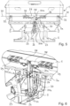
- the Fig. 3 shows a detailed view of one of the booms 3 in its operating position.
- the boom 3 which in the present case is pivotally mounted on the machine frame 2 by means of a support frame 10, comprises a plurality of - in the present case four - boom segments 3a, 3b, 3c, 3d which are pivotally linked to one another, namely - each in the unfolded operating position of the boom 3 according to the Fig. 3 considered - an inner, first boom segment 3a, a second innermost, second boom segment 3b, a third innermost or second outermost, third boom segment 3c and an outer, fourth boom segment 3d.
- a motor actuator engages on the first boom segment 3a of the boom 3 4, which in the present exemplary embodiment is formed by a piston/cylinder unit, for example electrically or hydraulically actuated and preferably remotely controllable, and serves to move the boom 3 between its primarily vertical transport and rest position (cf. the Fig. 1 and 2 ) and its primarily horizontal operating position (cf. the Fig. 3 ) to pivot or fold out/in.
- a piston/cylinder unit for example electrically or hydraulically actuated and preferably remotely controllable, and serves to move the boom 3 between its primarily vertical transport and rest position (cf. the Fig. 1 and 2 ) and its primarily horizontal operating position (cf. the Fig. 3 ) to pivot or fold out/in.
- One end of the piston/cylinder unit of the motor actuator 4 is articulated on the first boom segment 3a of the boom 3, while the other end of the piston/cylinder unit of the motor actuator 4 is articulated on the support frame 10 of the respective boom 3, on which the first boom segment 3a of
- the first boom segment 3a can in this way about an approximately horizontal first pivot axis A 1 between its in the Fig. 3 shown operating position, in which it extends approximately horizontally and transversely to the longitudinal axis of the distribution machine, and its rest position according to Fig. 1 or 2, in which it is essentially vertically upwards on one of the long sides of the distribution machine (the support frame 10 is in its operating position according to Fig. 2 ) or on the rear side (the support frame 10 is also in its transport and rest position according to Fig. 1 ) is folded, can be swiveled back and forth.
- the second boom segment 3b is pivotally connected to the first boom segment 3a about a second pivot axis A 2 - based on the unfolded operating position of the boom 3 - for example, in order to move it between its position Fig. 3 illustrated operating position, in which it extends approximately transversely to the direction of travel of the distribution machine, and its rest position, in which, for example, it is essentially parallel to the first boom segment 3a is folded (cf. the Fig. 1 and 2 ), to be able to pivot back and forth, which can be done manually or, in particular, in a remotely controllable manner using a motor, for example hydraulically or electrically (not shown).
- a motor for example hydraulically or electrically (not shown).
- the third boom segment 3c is pivotally articulated at the end of the second boom segment 3b opposite the first boom segment 3a about a - based on the unfolded operating position of the boom 3 - for example a vertical, third pivot axis A 3 in order to move it between its in the Fig. 3 illustrated operating position, in which it extends approximately transversely to the direction of travel of the distribution machine, and its rest position, in which it is folded, for example, essentially parallel against the first 3a and second boom segment 3b (cf. the Fig. 1 and 2 ), to be able to pivot back and forth, which in turn can be done manually or in particular in a remotely controllable manner by motor, for example hydraulically or electrically (not shown).
- motor for example hydraulically or electrically (not shown).
- the fourth boom segment 3d is finally pivotally articulated at the end of the third boom segment 3c opposite the second boom segment 3b about a - based on the unfolded operating position of the boom 3 - for example a horizontal, fourth pivot axis A 4 in order to move it between its in the Fig. 3 illustrated operating position, in which it extends approximately transversely to the direction of travel of the distribution machine, and its rest position, in which it is folded, for example, essentially parallel against the first 3a, second 3b and third boom segment 3c (cf. the Fig. 1 and 2 ), to be able to pivot back and forth, which in turn can be done manually or in particular in a remotely controllable manner by motor, for example hydraulically or electrically (not shown).
- motor for example hydraulically or electrically (not shown).
- a respective support frame 10 carrying a respective boom 3 is located in its position Fig. 2 shown operating position on the side of the storage container 1, the booms 3 can be moved out of their transport and rest position by pivoting their boom segments 3a, 3b, 3c, 3d in the aforementioned manner ( Fig. 1 and 2 ) into their operating position ( Fig. 3 ) transfer (and vice versa). If the booms 3 are in such an operating position Fig.
- the delivery line sections picked up by a respective boom 3 at different distances from the longitudinal axis of the distribution machine at distribution elements (not visible in the drawing), which can be formed, for example, by baffle plates or plates, seed coulters or the like.
- the distribution machine which in the present case is designed as a pneumatic fertilizer spreader, includes one or in particular two blowers (also not visible in the drawing), which are used to generate an air delivery flow for transporting the material to be distributed using the metering elements through the delivery lines.
- a pressure line of each blower has, for example, in a manner known from the prior art, an outlet assigned to each dosing element, which opens upstream of a respective dosing element to a respective air distributor, which distributes the compressed air to the outlet assigned to each dosing element Number of delivery lines divided.
- each delivery line is assigned a transfer chamber, which can be equipped in the usual way with an injector comprising, for example, a nozzle and a diffuser, and into which the metered material to be distributed is transferred by the respective metering element.
- Each support frame 10 can, for example, be essentially formed by a rectangular frame extending in a vertical plane, on the upper longitudinal member 10b of which one end of the piston/cylinder unit of the motor actuator 4 (cf. the Fig.
- each boom 3 is pivotally articulated, while on its lower longitudinal beam 10a the first boom segment 3a of a respective boom 3 is pivotally articulated about the axis A 1 (see also the Fig. 3 ).
- the support frames 10 of each boom 3 are between their transport and rest positions on the back of the storage container 1 according to the Fig. 1 and their operating position on the side of the storage container 1 according to the Fig. 2 can be pivoted about vertical pivot axes, which can also be done using suitable motorized actuators, as in the one cited above DE 20 2020 001 692 U1 is explained in detail.
- the lever 20 comprises, on the one hand, a first lever arm 20a, which extends approximately vertically upwards from its pivot axis S in a normal position of the lever 20, and a second lever arm 20b, which extends from its pivot axis S in the normal position of the lever 20 extends approximately vertically downwards.
- a respective boom 3 At the (upper) end of the first lever arm 20a remote from its pivot axis S there is a respective boom 3 (cf. the Fig.
- a suspension element 21 which in the present case is formed by a metal cable, for example in the form of a steel cable, and extends transversely outwards from the end of the first lever arm 20a of the lever 20 remote from the pivot axis the machine frame 2 is guided by roller arrangements 22 and fixed to a respective boom 3.
- the steel cables of the suspension means 21 are fixed to a respective boom 3 at a greater distance from the longitudinal axis of the distribution machine than the piston/cylinder unit of the motorized actuator 4, for example in the area of the end remote from the longitudinal axis of the distribution machine of the first boom segment 3a are attached to the latter.
- the second lever arm 20b of the lever 20 is fixed at its (lower) end remote from the pivot axis S in relation to the machine frame 2 or to the storage container 1, which in the present exemplary embodiment is done by means of a first actuator 23, which is provided by a preferably electrical, piston / cylinder unit is formed, which is articulated on the one hand to the lower end of the second lever arm 20b of the lever 20 and on the other hand to the machine frame 2.
- a first actuator 23 which is provided by a preferably electrical, piston / cylinder unit is formed, which is articulated on the one hand to the lower end of the second lever arm 20b of the lever 20 and on the other hand to the machine frame 2.
- the first actuator 23 serves to actuate the lever 20 as required in such a way that it is pivoted from an approximately vertical normal position at a desired angle about the pivot axis S and in this way to ensure a slope compensation of the boom 3 in its operating position by raising one boom 3 and lowering the other boom 3.
- an axial section of the lever 20 is designed to be elastically flexible transversely to the longitudinal axis of the distribution machine, which is elastic resiliently designed axial section of the lever 20 in the present case is the second lever arm 20b.
- the second lever arm 20b of the lever 20 has two leaf springs 24 for this purpose, which are arranged parallel to one another and whose extension planes run parallel to the longitudinal axis of the distribution machine, so that in the event of a bending deformation of the two leaf springs 24, the lever 20 moves slightly about its pivot axis S is pivoted and the boom 3 fixed to the first lever arm 20a by means of the support means 21 can swing synchronously downwards or upwards in opposite directions.
- Leaf springs are used to ensure good elastic compliance while still maintaining high mechanical stability 24 of the second lever arm 20b arranged at a distance from one another and rigidly fixed to the first lever arm 20a in the area of the pivot axis S of the lever 20, such as by means of screws.
- the leaf springs 24 are accommodated in the spaces between parallel rollers 25 of a roller pack (cf. in particular Fig. 8 ), which are fixed in a support cage 26.
- the first actuator 23 is articulated on the support cage 26, and on the other hand, the support cage 26 provided with the roller pack forms the end remote from the pivot axis S of an additional lever 27 which serves for stabilization purposes and which is designed to be essentially rigid and coaxial with the lever 20 about the pivot axis S is pivotally mounted on the machine frame 2, but independent of the lever 20.
- a sensor (not shown in the drawing) can also be arranged on the additional lever 27 in order to detect the respective angular position of the additional lever 27 and consequently also of the lever 20 when this is moved into a (for example non-vertical) slope compensation position of the boom by means of the first actuator 23 3 has been moved.
- the pendulum compensation is therefore also effective when the booms 3 have been moved into a slope compensation position by means of the first actuator 23, in which they are aligned approximately parallel to the slope.
- a respective steel cable of a respective suspension element 21 of a respective boom 3 is not fixed directly to the (upper) end of the first lever arm 20a of the lever remote from the pivot axis S, but rather via a second actuator 28, which is similar to the first actuator 23 from a, preferably electrical, piston/cylinder unit can be formed, which is effective between the (upper) end of the first lever arm 20a of the lever 20 remote from the pivot axis S and a respective support means 21.
- a second actuator 28 which is similar to the first actuator 23 from a, preferably electrical, piston/cylinder unit can be formed, which is effective between the (upper) end of the first lever arm 20a of the lever 20 remote from the pivot axis S and a respective support means 21.
- a respective second actuator 28 serves to lift a respective boom 3 from its "normal" operating position as needed, for example to avoid a collision with obstacles in the field.
- the piston of a respective piston/cylinder unit of a respective second actuator 28 is articulated at the (upper) end of the first lever arm 20a of the lever 20 remote from the pivot axis S, while the cylinder of a respective piston/cylinder unit of a respective second actuator 28 is articulated a guide 29 arranged stationarily on the storage container 1 is guided.
- the lever 20 is in its - here: vertical - normal position, in which both are in their operating position (see also the Fig. 3 ) spent boom 3 are arranged primarily horizontally or, as is the case here, the longitudinal axes of the boom segments close to the distribution machine are inclined slightly upwards. Both the first actuator 23 and the two second actuators 28 are also in their normal position.
- the second lever arm 20b of the lever 20, which is designed to be resiliently elastic by means of the leaf springs 24 (see above), ensures an elastic pendulum compensation of the boom 3 in the manner described above.
- the second lever arm 20b of the lever 20, which is designed to be resiliently elastic by means of the leaf springs 24 (see above), ensures an elastic pendulum compensation of the boom 3 in a corresponding manner. It goes without saying that by actuating the first actuator 23 in such a way that the piston of its piston/cylinder unit is pulled slightly out of the cylinder (not shown), the lever 20 is pivoted in the opposite direction and in this way the right boom 3 can be raised by an angle, while the left boom can be lowered by a corresponding angle to ensure slope compensation in the opposite direction. The ones further up The pendulum compensation function described remains active even in such a slope compensation position of the boom 3.
- Such a "V" position of the boom 3 can in particular protect the boom 3 in the event of very strong fluctuations of the distribution machine or a tractor carrying it, such as a tractor, for example when entering and exiting the headland, and / or to prevent a collision with obstacles present in the field, without having to completely transfer the boom 3 into its transport and rest position using the motorized actuator 4 and/or without having to leave the respective lane in the field and avoid the obstacle over a large area .
- the pendulum compensation function described above remains active and is able to effectively limit extreme positions of the boom 3.
- the booms 3 can in particular be provided with sensors (not shown in the drawing) which are used to record the distance of a respective boom 3 are formed from the ground, the sensors being connected to a control and / or regulating device, also not shown in the drawing, for actuating the first actuator 23 and / or the second actuator 28 in order to control the latter depending on the ground distances detected by sensors Activate the boom 3 and move the boom 3, for example, into a slope compensation position according to the Fig. 12B and/or to a raised "V" position corresponding to the Fig. 12C to transfer.
Description
Die Erfindung betrifft eine landwirtschaftliche Verteilmaschine, umfassend:
- wenigstens einen von einem Maschinenrahmen getragenen Vorratsbehälter zur Aufnahme von Verteilgut;
- wenigstens ein dem Vorratsbehälter nachgeordnetes Dosierorgan;
- wenigstens zwei an dem Maschinenrahmen und/oder an dem Vorratsbehälter schwenkbar gelagerte Ausleger;
- eine Mehrzahl an von einem jeweiligen Ausleger getragenen und mit Abstand voneinander angeordneten Verteilorganen; und
- eine Mehrzahl an Förderleitungen, welche zur Überführung des Verteilgutes von dem Dosierorgan an die Verteilorgane dienen und von welchen zumindest endständige Förderleitungsabschnitte von den Auslegern getragen sind,
- at least one storage container carried by a machine frame for receiving distributed goods;
- at least one metering element arranged downstream of the storage container;
- at least two booms pivotably mounted on the machine frame and/or on the storage container;
- a plurality of distribution members carried by a respective boom and arranged at a distance from one another; and
- a plurality of delivery lines which are used to transfer the material to be distributed from the dosing element to the distribution elements and of which at least terminal delivery line sections are carried by the booms,
Landwirtschaftliche Verteilmaschinen der vorgenannten Art können einerseits in leichter Bauart als Anbaugeräte konzipiert sein, welche mit dem Dreipunkt einer Zugmaschine, wie eines Traktors, gekoppelt werden können; anderseits können sie in schwerer Bauart auf einen achsgestützten Nachläufer oder einen Selbstfahrer aufgesetzt sein. Sie umfassen üblicherweise seitlich nach außen ragende Ausleger, welche in unterschiedlichem Abstand voneinander endende Förderleitungsabschnitte aufnehmen und insbesondere im Falle von verhältnismäßig großen Arbeitsbreiten, wie beispielsweise von etwa 18 m, 24 m, 30 m oder dergleichen, eine Mehrzahl an schwenkbar aneinander angelenkten Auslegersegmenten umfassen, um die Ausleger zwischen einer Betriebsposition, in welcher sie sich vornehmlich horizontal in entgegengesetzte Richtungen quer zur Längsachse der Verteilmaschine, also im Wesentlichen quer zu Fahrtrichtung der Verteilmaschine, erstrecken und die ausgeklappten Auslegersegmente im Wesentlichen horizontal und linear hintereinander angeordnet sind, und einer Transport- und Ruhe- oder auch Reinigungsposition, in welcher sich die Ausleger vornehmlich vertikal erstrecken und die Auslegersegmente im Wesentlichen parallel zueinander aneinander angeklappt sind, hin und her zu verschwenken, so dass die landwirtschaftliche Verteilmaschine z.B. über öffentliche Straßen zu ihrem Einsatzort auf dem Feld verbracht werden kann.Agricultural distribution machines of the aforementioned type can, on the one hand, be designed in a lightweight design as attachments that can be coupled to the three-point connection of a tractor, such as a tractor; On the other hand, they can be heavy-duty and mounted on an axle-supported trailer or a self-propelled vehicle. They usually include laterally outwardly projecting booms, which accommodate conveyor line sections that end at different distances from one another and, in particular in the case of relatively large working widths, such as approximately 18 m, 24 m, 30 m or the like, comprise a plurality of boom segments pivotally linked to one another, around the booms between an operating position in which they extend primarily horizontally in opposite directions transverse to the longitudinal axis of the distribution machine, i.e. essentially transverse to the direction of travel of the distribution machine, and the unfolded boom segments are arranged essentially horizontally and linearly one behind the other, and a transport and Resting or cleaning position, in which the booms extend primarily vertically and the boom segments are folded essentially parallel to one another, back and forth, so that the agricultural distribution machine can be moved, for example, via public roads to its place of use in the field.
Handelt es sich bei einer solchen landwirtschaftlichen Verteilmaschine beispielsweise um eine pneumatische Verteilmaschine, so dient zur Förderung des in dem Vorratsbehälter auf Vorrat gehaltenen, in der Regel pulver- oder partikelförmigen Verteilgutes, wie Dünger, Saatgut und dergleichen, ein Gebläse, dessen Druckleitung sich z.B. an einen Auslass eines oder mehrerer, dem Vorratsbehälter nachgeordneter Dosierorgane, welche beispielsweise eine gesteuert und/oder geregelt drehangetriebene Dosierwalze umfassen, anschließt und in einem Druckverteiler mündet, an welchen sich eine Mehrzahl an Förderleitungen anschließt. Zwischen dem Druckverteiler und den Förderleitungen angeordnete Übergabekammern, welche zweckmäßigerweise mit jeweils eine Düse und einen Diffusor umfassenden Injektoren ausgestattet sein können, dienen zur Übergabe des Verteilgutes von dem Dosierorgan an die Förderleitungen, um sicherzustellen, dass jeder Förderleitung die gewünschte Menge an Verteilgut aufgegeben wird. Das Verteilgut wird schließlich pneumatisch über die nach außen umgelenkten und sich entlang der jeweiligen Ausleger erstreckenden Förderleitungsabschnitte bis zu deren Ende gefördert, wo das Verteilgut an entsprechende Verteilorgane überführt wird, welche jeweils mit Abstand voneinander an den Auslegern bzw. an dessen Auslegersegmenten angeordnet sind. Die Verteilorgane können im Falle eines pneumatischen Düngerstreuers z.B. nach Art von Prallplatten bzw. Pralltellern ausgestaltet sein, auf welche das in einer jeweiligen Förderleitung pneumatisch transportierte Verteilgut auftrifft und von dort im Wesentlichen fächerförmig auf dem Boden abgelegt wird. Im Falle von pneumatischen Sämaschinen oder Drillmaschinen können die Verteilorgane z.B. von Säscharen oder dergleichen gebildet sein, welche gleichfalls über den jeweiligen Förderleitungsabschnitt mit pneumatisch transportiertem Verteilgut versorgt werden. Eine derartige pneumatische Verteilmaschine in Form eines pneumatischen Düngerstreuers ist beispielsweise aus der
Handelt es sich bei einer landwirtschaftlichen Verteilmaschine der eingangs genannten Art beispielsweise um eine sogenannte Feldspritze, so dienen zur Dosierung und Förderung des in dem - in diesem Fall üblicherweise von einem Tank gebildeten - Vorratsbehälter auf Vorrat gehaltenen, in der Regel flüssigen Verteilgutes, wie Pflanzenschutzmitteln, Pestiziden, Herbiziden und dergleichen, eine oder insbesondere mehrere Pumpen, deren Förderleitungen wiederum nach außen umgelenkt sind, sich entlang der jeweiligen Ausleger erstrecken und zur Versorgung eines jeweiligen Verteilorgans dienen, wobei die Verteilorgane gleichfalls jeweils mit Abstand voneinander an den Auslegern bzw. an deren Auslegersegmenten angeordnet sind. Die Verteilorgane können in diesem Fall z.B. nach Art von, insbesondere hinsichtlich ihrer Verteilmenge steuerbaren, Düsen ausgestaltet sein, welche das flüssige Verteilgut in der jeweils vorgesehenen Verteilungsbreite versprühen.If an agricultural distribution machine of the type mentioned at the beginning is, for example, a so-called field sprayer, it is used to meter and deliver the generally liquid distribution material, such as plant protection products, which is stored in the storage container - in this case usually formed by a tank. Pesticides, herbicides and the like, one or in particular several pumps, the delivery lines of which are in turn deflected outwards, extend along the respective booms and serve to supply a respective distribution element, the distribution elements also being at a distance from one another on the booms or on their boom segments are arranged. In this case, the distribution elements can, for example, be designed in the manner of nozzles, in particular with regard to their distribution quantity, which spray the liquid distribution material in the respective intended distribution width.
Als in konstruktiver Hinsicht relativ aufwändig gestaltet sich häufig der Aufbau der Ausleger sowie deren schwenkbare Befestigung an dem Maschinenrahmen und/oder an dem Vorratsbehälter der Verteilmaschine unter Gewährleistung einer Verlagerung derselben zwischen ihrer Betriebsposition und ihrer Transport- und Ruheposition mittels je eines motorischen Stellantriebs, welcher üblicherweise hydraulische oder elektrische Kolben-/Zylindereinheiten umfasst, welche zwischen einem jeweiligen Ausleger - bzw. im Falle eines aus mehreren Auslegersegmenten gebildeten Ausleger: zwischen dem inneren, der Längsachse der Verteilmaschine nahen Auslegersegment eines jeweiligen Auslegers - und dem Maschinenrahmen und/oder dem Vorratsbehälter der Verteilmaschine wirksam sind. Die Ausleger müssen hierbei mit zunehmender Arbeitsbreite und hiermit einhergehender zunehmender Gesamtlänge erhebliche Lasten sowie insbesondere Drehmomente aufnehmen, sollten unter Sicherstellung der notwendigen mechanischen Stabilität aber gleichwohl nicht übermäßig massiv ausgestaltet sein, um das Gesamtgewicht der landwirtschaftlichen Verteilmaschine in vertretbaren Grenzen zu halten, wobei sie vorzugsweise zugleich die Klappfunktion der einzelnen Auslegersegmente relativ zueinander zu gewährleisten haben. Ein Problem besteht dabei insbesondere darin, dass es während des Betriebs gattungsgemäßer landwirtschaftlicher Verteilmaschinen auf unebenem Gelände auch bei relativ langsamer Fahrt zu erheblichen Schwankungen der Verteilmaschine kommt, welche sich über die erhebliche Länge der Ausleger potenziert, so dass infolge der fortwährenden mechanischen Stoßbelastungen die Gefahr einer Beschädigung der Ausleger selbst und/oder deren motorischer Stellantriebe besteht. Da im Falle solcher Schwankungen der Verteilmaschine auch der Abstand der von den Auslegern getragenen Verteilorgane gegenüber dem Boden großen Veränderungen unterliegt (insbesondere im Falle der relativ weit außen angeordneten Verteilorgane), wird hierbei auch die Verteilgenauigkeit von in Form von Pralltellern oder Düsen ausgestalteten Verteilorganen in erheblichem Maße beeinträchtigt, da diese auf einen vorherbestimmten Abstand vom Boden ausgelegt sind, um infolge Überlappung der Verteilungsbreiten von jeweils benachbarten Verteilorgane für eine möglichst konstante Querverteilung über die gesamte Arbeitsbreite der Verteilmaschine zu sorgen.The construction of the booms and their pivotable attachment to the machine frame and/or to the storage container of the distribution machine are often relatively complex in terms of construction, ensuring that they can be moved between their operating position and their transport and rest position by means of a motorized actuator, which is usually the case hydraulic or electric piston/cylinder units, which are located between a respective boom - or in the case of a boom formed from several boom segments: between the inner, longitudinal axis of the distribution machine close boom segment of a respective boom - and the machine frame and / or the storage container of the distribution machine are effective. As the working width and the associated increasing overall length increase, the booms must absorb considerable loads and, in particular, torques, but should not be made excessively massive while ensuring the necessary mechanical stability in order to keep the total weight of the agricultural distribution machine within acceptable limits, preferably at the same time must ensure the folding function of the individual boom segments relative to one another. A particular problem is that during the operation of generic agricultural distribution machines on uneven terrain, even when driving relatively slowly, there are significant fluctuations in the distribution machine, which increase over the considerable length of the boom, so that due to the constant mechanical shock loads there is a risk of There is damage to the boom itself and/or its motor actuators. Since in the event of such fluctuations in the distribution machine, the distance between the distribution elements carried by the booms and the ground is also subject to major changes (particularly in the case of the distribution elements arranged relatively far out), the distribution accuracy of distribution elements designed in the form of baffle plates or nozzles is also significantly affected Dimensions are affected because they are designed at a predetermined distance from the ground in order to ensure the most constant possible transverse distribution over the entire working width of the distribution machine due to the overlap of the distribution widths of adjacent distribution elements.
Die Gefahr einer mechanischen Beschädigung der Ausleger einschließlich deren motorischer Stellantriebe besteht um so mehr, als ab einer gewissen, auch nur kurzzeitigen Neigungsstellung der Verteilmaschine, wenn diese beispielsweise relativ starke Unebenheiten des Bodens überfährt, die Gefahr droht, dass die Ausleger auf dem Boden aufschlagen. Entsprechendes gilt im Falle des Betriebs der Verteilmaschine an einer Hanglage, welcher sich zudem insoweit als problematisch erweist, als die Abstände der von den Auslegern getragenen Verteilorgane von dem Boden auch bei verhältnismäßig "ruhiger" Fahrt über relativ ebenes Gelände aufgrund der Hangneigung erheblich variieren können, was wiederum mit dem oben beschriebenen Problem einer beeinträchtigten Verteilgenauigkeit einhergeht. Eine weitere vorbekannte landwirtschaftliche Verteilmaschine ist in der
Der Erfindung liegt daher die Aufgabe zugrunde, eine landwirtschaftliche Verteilmaschine der eingangs genannten Art auf einfache und kostengünstige Weise dahingehend weiterzubilden, dass unter zumindest weitestgehender Vermeidung der vorgenannten Nachteile die Gefahr einer Beschädigung der Ausleger einschließlich deren motorischer Stellantriebe während des Betriebs unter Gewährleistung einer hohen Verteilgenauigkeit minimiert wird.The invention is therefore based on the object of developing an agricultural distribution machine of the type mentioned in a simple and cost-effective manner in such a way that, while at least largely avoiding the aforementioned disadvantages, the risk of damage to the booms, including their motorized actuators, is minimized during operation while ensuring high distribution accuracy becomes.
Erfindungsgemäß wird diese Aufgabe bei einer landwirtschaftlichen Verteilmaschine der eingangs genannten Art dadurch gelöst, dass an dem Maschinenrahmen und/oder an dem Vorratsbehälter ein Hebel um eine sich im Wesentlichen parallel zur Längsachse der Verteilmaschine erstreckende Schwenkachse schwenkbar gelagert ist, wobei der Hebel einen ersten Hebelarm aufweist, an dessen seiner Schwenkachse fernem Ende ein jeweiliger Ausleger in seiner Betriebsposition mittels wenigstens eines Tragmittels aufgehängt ist, und wobei der Hebel einen zweiten Hebelarm aufweist, dessen seiner Schwenkachse fernes Ende in Bezug auf den Maschinenrahmen und/oder auf den Vorratsbehälter festgestellt ist, wobei zumindest ein Axialabschnitt des Hebels quer zur Längsachse der Verteilmaschine elastisch nachgiebig ausgestaltet ist, um für einen Pendelausgleich der Ausleger in deren Betriebsposition zu sorgen.According to the invention, this object is achieved in an agricultural distribution machine of the type mentioned in that a lever is pivotally mounted on the machine frame and / or on the storage container about a pivot axis extending essentially parallel to the longitudinal axis of the distribution machine, the lever having a first lever arm , at the end of which a respective boom is suspended in its operating position by means of at least one suspension element, at the end remote from its pivot axis, and wherein the lever has a second lever arm, the end of which is remote from its pivot axis is fixed in relation to the machine frame and / or to the storage container, wherein at least an axial section of the lever transverse to The longitudinal axis of the distribution machine is designed to be elastically flexible in order to ensure pendulum compensation of the boom in its operating position.
Die erfindungsgemäße Ausgestaltung sieht folglich vor, dass die jeweils an dem Maschinenrahmen und/oder an dem Vorratsbehälter der Verteilmaschine schwenkbar gelagerten und mittels ihres jeweiligen motorischen Stellantriebs zwischen der Betriebsposition und der Transport- und Ruheposition betätigbaren Ausleger mittels ihrer Tragmittel mechanisch miteinander gekoppelt sind, wobei die Tragmittel eines jeweiligen Auslegers an dem ersten Hebelarm des schwenkbar gelagerten Hebels festgelegt sind, so dass die Ausleger gemeinsam an dem ersten Hebelarm des Hebels aufgehängt sind. Aufgrund der elastisch nachgiebigen Ausgestaltung zumindest eines Axialabschnittes des Hebels - sei es an dessen ersten und/oder sei es an dessen zweitem Hebelarm - vermag sich der um seine etwa parallel zur Längsachse der Verteilmaschine angeordnete Schwenkachse schwenkbar gelagerte Hebel elastisch zu verformen, wobei er hierbei geringfügig um seine Schwenkachse verschwenkt werden kann, so dass im Falle von mechanischen Stößen, Schwingungen, Vibrationen etc. das der Schwenkachse ferne Ende des ersten Hebelarms des Hebels, an welchem die Haltemittel eines jeweiligen Auslegers festgelegt sind, elastisch quer zur Längsachse der Verteilmaschine ausweichen kann, so dass mechanische Stoßbelastungen der Ausleger einerseits abgedämpft, andererseits mechanische Belastungen des einen Auslegers von dem anderen Ausleger aufgenommen werden. Das der Schwenkachse ferne Ende des zweiten Hebelarms des Hebels bleibt dabei in der vorgesehenen Betriebsposition der Ausleger festgestellt. Auf diese Weise ergibt sich ein konstruktiv einfacher, aber gleichwohl sehr wirksamer Pendelausgleich der Ausleger, wenn sich diese in ihrer Betriebsposition befinden.The embodiment according to the invention therefore provides that the booms, which are each pivotally mounted on the machine frame and/or on the storage container of the distribution machine and can be actuated between the operating position and the transport and rest position by means of their respective motorized actuator, are mechanically coupled to one another by means of their support means, whereby the Support means of a respective boom are fixed to the first lever arm of the pivotally mounted lever, so that the booms are suspended together on the first lever arm of the lever. Due to the elastically flexible design of at least one axial section of the lever - be it on its first and/or on its second lever arm - the lever, which is pivotally mounted about its pivot axis arranged approximately parallel to the longitudinal axis of the distribution machine, is able to deform elastically, whereby it is slightly can be pivoted about its pivot axis, so that in the event of mechanical shocks, oscillations, vibrations, etc., the end of the first lever arm of the lever remote from the pivot axis, to which the holding means of a respective boom are fixed, can deflect elastically transversely to the longitudinal axis of the distribution machine, so that mechanical shock loads on the boom are dampened on the one hand, and on the other hand mechanical loads on one boom are absorbed by the other boom. The end of the second lever arm of the lever remote from the pivot axis remains fixed in the intended operating position of the boom. This results in a structurally simple but nevertheless very effective pendulum compensation the boom when they are in their operating position.
In konstruktiver Hinsicht kann zweckmäßigerweise vorgesehen sein, dass sich der Hebel vornehmlich in Vertikalrichtung erstreckt, wobei sich der erste Hebelarm insbesondere von der Schwenkachse des Hebels vornehmlich nach oben erstrecken kann, wohingegen sich der zweite Hebelarm insbesondere von der Schwenkachse des Hebels vornehmlich nach unten erstrecken kann.From a structural point of view, it can expediently be provided that the lever extends primarily in the vertical direction, wherein the first lever arm can extend primarily upwards, in particular from the pivot axis of the lever, whereas the second lever arm can extend primarily downwards, in particular from the pivot axis of the lever .
Gemäß einer konstruktiv einfachen und mechanisch robusten Ausführungsform kann der elastisch nachgiebige Axialabschnitt des Hebels vorzugsweise wenigstens zwei Blattfedern aufweisen, deren Erstreckungsebenen im Wesentlichen parallel zueinander und insbesondere im Wesentlichen parallel zur Längsachse der Verteilmaschine angeordnet sind, so dass eine elastische Nachgiebigkeit des Hebels quer zur Längsachse der Verteilmaschine sichergestellt ist, um auf die Ausleger einwirkende mechanische Belastungen aufzunehmen und zu dämpfen.According to a structurally simple and mechanically robust embodiment, the elastically flexible axial section of the lever can preferably have at least two leaf springs, the planes of extension of which are arranged essentially parallel to one another and in particular essentially parallel to the longitudinal axis of the distribution machine, so that an elastic resilience of the lever transversely to the longitudinal axis of the Distribution machine is ensured to absorb and dampen mechanical loads acting on the boom.
Aus Gründen einer sehr hohen mechanischen Stabilität kann es vorteilhaft sein, wenn nur einer der Hebelarme des Hebels von den wenigstens zwei Blattfedern gebildet ist, während der andere Hebelarm im Wesentlichen starr ausgestaltet ist, wobei vorzugsweise der zweite Hebelarm des Hebels von den wenigstens zwei Blattfedern gebildet sein kann.For reasons of very high mechanical stability, it can be advantageous if only one of the lever arms of the lever is formed by the at least two leaf springs, while the other lever arm is designed to be essentially rigid, the second lever arm of the lever preferably being formed by the at least two leaf springs can be.
Um für eine gute elastische Nachgiebigkeit des Hebels bei einer gleichwohl hohen mechanischen Stabilität zu sorgen, können die Blattfedern des nachgiebig elastisch ausgestalteten Axialabschnittes des Hebels vorteilhafterweise mit Abstand voneinander angeordnet sein, so dass die voneinander beabstandeten Blattfedern gemeinsam nach Art eines "Parallelogramms" elastisch verformbar sind.In order to ensure good elastic compliance of the lever while still maintaining high mechanical stability, the leaf springs of the resiliently elastic axial section of the lever can advantageously be arranged at a distance from one another, so that the spaced leaf springs can be elastically deformed together in the manner of a "parallelogram". .
Die Blattfedern eines der Hebelarme, z.B. des zweiten Hebelarms, können beispielsweise im Bereich der Schwenkachse des Hebels starr an dem anderen Hebelarm, z.B. an dem ersten Hebelarm, festgelegt sein, wobei sie beispielsweise an dem anderen, z.B. im Wesentlichen starren, Hebelarm verschraubt oder verschweißt sein können.The leaf springs of one of the lever arms, for example the second lever arm, can, for example, be rigidly fixed to the other lever arm, for example on the first lever arm, in the area of the pivot axis of the lever, for example being screwed or welded to the other, for example essentially rigid, lever arm could be.
An dem der Schwenkachse fernen Ende des Hebels können die Blattfedern eines der Hebelarme, z.B. des zweiten Hebelarms, vorzugsweise in den Zwischenräumen von parallel angeordneten Walzen eines Walzenpaketes aufgenommen sein, so dass sie einerseits voneinander beabstandet, andererseits ohne eine lokal übermäßige Biegebeanspruchung sicher und zuverlässig befestigt sind, wobei sie im Falle einer Biegebeanspruchung entlang der Oberfläche der Walzen abrollen können. Das Walzenpaket kann dabei insbesondere in einem Tragkäfig angeordnet sein, wobei die Walzen des Walzenpaketes an dem Tragkäfig festgelegt sein können.At the end of the lever remote from the pivot axis, the leaf springs of one of the lever arms, e.g. the second lever arm, can preferably be accommodated in the spaces between parallel rollers of a roller pack, so that they are spaced apart from one another on the one hand, and securely and reliably fastened on the other hand without locally excessive bending stress are, whereby they can roll along the surface of the rollers in the event of bending stress. The roller pack can in particular be arranged in a support cage, the rollers of the roller pack being able to be fixed to the support cage.
Um für eine größtmögliche mechanische Stabilität des Hebels bei einer gleichwohl hohen elastischen Nachgiebigkeit desselben zu sorgen, kann der nachgiebig elastisch ausgestaltete Hebelarm des Hebels, z.B. dessen zweiter Hebelarm, vorzugsweise mittels eines Zusatzhebels stabilisiert sein, wobei der Zusatzhebel koaxial zu dem Hebel schwenkbar gelagert und an dem der Schwenkachse des nachgiebig elastisch ausgestalteten Hebelarms des Hebels fernen Ende mit diesem verbunden ist. Der in herkömmlicher Weise im Wesentlichen starre und beispielsweise nach Art einer Konsole ausgestaltete Zusatzhebel, welcher koaxial zu dem Hebel schwenkbar gelagert ist, ohne drehfest mit dem Hebel verbunden zu sein, fixiert den elastisch nachgiebig ausgestalteten Hebelarm des Hebels auf diese Weise einerseits an der Schwenkachse des Hebels, andererseits an dem der Schwenkachse fernen Ende des elastisch nachgiebig ausgestalteten Hebelarms des Hebels, wobei aber nur der elastisch nachgiebig ausgestaltete Hebelarm des Hebels elastisch verformt werden kann, um für den erfindungsgemäßen Pendelausgleich der Ausleger zu sorgen.In order to ensure the greatest possible mechanical stability of the lever while still maintaining a high level of elastic flexibility, the resiliently designed lever arm of the lever, for example its second lever arm, can preferably be stabilized by means of an additional lever, the additional lever being pivotally mounted and attached coaxially to the lever the end remote from the pivot axis of the resiliently elastic lever arm of the lever is connected to it. The additional lever, which is essentially rigid in a conventional manner and is designed, for example, in the manner of a console, which is pivotally mounted coaxially to the lever without being connected to the lever in a rotationally fixed manner, fixes the elastically flexible lever arm of the lever in this way on the one hand on the pivot axis of the lever Lever, on the other hand, at the end of the elastically flexible one that is remote from the pivot axis Lever arm of the lever, but only the elastically flexible lever arm of the lever can be elastically deformed in order to ensure the pendulum compensation of the boom according to the invention.
Die Verbindung eines solchen Zusatzhebels mit dem der Schwenkachse des elastisch nachgiebig ausgestalteten Hebelarms fernen Ende des Hebels kann dabei beispielsweise mittels des vorstehend beschriebenen Walzenpaketes geschehen, welches an dem Zusatzhebel angeordnet ist. Der Tragkäfig mit dem Walzenpaket, zwischen dessen parallel angeordneten Walzen die Blattfedern eines der Hebelarme des Hebels aufgenommen sind, kann zu diesem Zweck an dem der Schwenkachse fernen Ende des Zusatzhebels angeordnet sein.The connection of such an additional lever to the end of the lever remote from the pivot axis of the elastically flexible lever arm can be done, for example, by means of the roller pack described above, which is arranged on the additional lever. The support cage with the roller pack, between whose parallel rollers the leaf springs of one of the lever arms of the lever are accommodated, can be arranged for this purpose at the end of the additional lever remote from the pivot axis.
Während der zweite Hebelarm des Hebels an seinem der Schwenkachse fernen Ende grundsätzlich auch stationär an dem Maschinenrahmen und/oder an dem Vorratsbehälter festgestellt sein kann, um für den erfindungsgemäßen Pendelausgleich der Ausleger zu sorgen, kann gemäß einer vorteilhaften Weiterbildung vorgesehen sein, dass der zweite Hebelarm des Hebels an seinem der Schwenkachse fernen Ende an einem ersten Stellglied angelenkt ist, um den Hebel durch Betätigung des ersten Stellgliedes in verschiedenen, um die Schwenkachse verschwenkten Positionen in Bezug auf den Maschinenrahmen und/oder auf den Vorratsbehälter festzustellen und auf diese Weise für einen Hangausgleich der Ausleger in deren Betriebsposition zu sorgen. Wird der Hebel mittels des ersten Stellgliedes folglich um einen vorgegebenen Winkel um seine Schwenkachse verschwenkt, so erfährt das der Schwenkachse des Hebels ferne Ende des ersten Hebelarms, an welchem die Tragmittel der Ausleger festgelegt sind, eine Verlagerung quer zur Längsachse der Verteilmaschine, so dass der eine Ausleger um einen bestimmten Winkel angehoben wird, während der andere Ausleger um einen entsprechenden Winkel abgesenkt wird, wie es für die Fahrt an Hanglagen wünschenswert sein kann, damit die von den Auslegern getragenen Verteilorgane gewisse Mindest- bzw. Maximalabstände gegenüber dem Boden nicht unter- bzw. überschreiten, was aus den eingangs genannten Gründen zu einer ungleichmäßigen Querverteilung führen könnte.While the second lever arm of the lever can in principle also be fixed stationary on the machine frame and/or on the storage container at its end remote from the pivot axis in order to ensure the pendulum compensation of the boom according to the invention, according to an advantageous development it can be provided that the second lever arm of the lever is articulated at its end remote from the pivot axis on a first actuator in order to fix the lever by actuating the first actuator in different positions pivoted about the pivot axis in relation to the machine frame and / or to the storage container and in this way for slope compensation ensure the boom is in its operating position. If the lever is consequently pivoted by a predetermined angle about its pivot axis by means of the first actuator, the end of the first lever arm remote from the pivot axis of the lever, to which the suspension means of the boom are fixed, experiences a displacement transversely to the longitudinal axis of the distribution machine, so that the one boom is raised by a certain angle while the other boom is raised by a is lowered to the appropriate angle, as may be desirable when driving on slopes, so that the distribution elements carried by the booms do not fall below or exceed certain minimum or maximum distances from the ground, which leads to an uneven transverse distribution for the reasons mentioned at the beginning could.
Das erste Stellglied kann grundsätzlich in beliebiger bekannter Weise ausgestaltet sein und beispielsweise eine Kolben-/Zylindereinheit aufweisen, welche zwischen dem Maschinenrahmen und/oder dem Vorratsbehälter der Verteilmaschine und dem der Schwenkachse des Hebels fernen Ende des zweiten Hebelarms wirksam ist. Es kann dabei z.B. eine elektrische oder auch hydraulische Kolben-/Zylindereinheit umfassen, welche eine eigene Energieversorgung aufweisen oder an die Bordelektrik bzw. an das Hydrauliksystem eines Zugfahrzeugs, wie eines Traktors, anschließbar sein kann.The first actuator can basically be designed in any known manner and, for example, have a piston/cylinder unit which is effective between the machine frame and/or the storage container of the distribution machine and the end of the second lever arm remote from the pivot axis of the lever. It can, for example, include an electrical or hydraulic piston/cylinder unit, which can have its own energy supply or can be connected to the on-board electrical system or to the hydraulic system of a towing vehicle, such as a tractor.
Während die Tragmittel der Ausleger grundsätzlich auch unmittelbar an dem der Schwenkachse des Hebels fernen Ende des ersten Hebelarms festgelegt sein können, kann gemäß einer weiteren vorteilhaften Weiterbildung vorgesehen sein, dass ein jeweiliges Tragmittel eines jeweiligen Auslegers über je ein zweites Stellglied an dem der Schwenkachse des Hebels fernen Ende des ersten Hebelarms aufgehängt ist, um einen jeweiligen Ausleger durch Betätigung des jeweiligen zweiten Stellgliedes aus seiner Betriebsposition anzuheben und/oder abzusenken. Auf diese Weise kann ein jeweiliger Ausleger durch Betätigung eines jeweiligen zweiten Stellgliedes unabhängig voneinander aus einer im Wesentlichen horizontalen Betriebsposition nach oben angehoben werden, wie es beispielsweise bei der starken Schwankungen der Verteilmaschine erforderlich sein kann, und/oder um auf dem Feld vorhandene Hindernisse, wie Felsen, Büsche, Böschungen oder dergleichen, zu passieren, ohne dass die Gefahr besteht, dass der jeweilige Ausleger an ein solches Hindernis anstößt.While the support means of the boom can in principle also be fixed directly to the end of the first lever arm remote from the pivot axis of the lever, according to a further advantageous development it can be provided that a respective support means of a respective boom has a second actuator on the pivot axis of the lever is suspended at the distal end of the first lever arm in order to raise and/or lower a respective boom from its operating position by actuating the respective second actuator. In this way, a respective boom can be raised independently of one another from a substantially horizontal operating position by actuating a respective second actuator, as may be necessary, for example, in the event of strong fluctuations of the distribution machine, and/or around obstacles present in the field, such as rocks, bushes, embankments or the like, without the danger of that the respective boom hits such an obstacle.
Ein jeweiliges zweites Stellglied kann beispielsweise wiederum je eine Kolben-/Zylindereinheit aufweisen, welche zwischen dem der Schwenkachse des Hebels fernen Ende des ersten Hebelarms und einem jeweiligen Tragmittel eines jeweiligen Auslegers wirksam ist. Es kann dabei beispielsweise eine elektrische oder auch hydraulische Kolben-/Zylindereinheit umfassen, welche wiederum eine eigene Energieversorgung aufweisen oder an die Bordelektrik bzw. an das Hydrauliksystem eines Zugfahrzeugs, wie eines Traktors, anschließbar sein kann.A respective second actuator can, for example, in turn have a piston/cylinder unit, which is effective between the end of the first lever arm remote from the pivot axis of the lever and a respective support element of a respective boom. It can, for example, include an electrical or hydraulic piston/cylinder unit, which in turn can have its own energy supply or can be connected to the on-board electrical system or to the hydraulic system of a towing vehicle, such as a tractor.
In diesem Zusammenhang kann z.B. vorgesehen, dass
- der Kolben oder der Zylinder der Kolben-/Zylindereinheit eines jeweiligen zweiten Stellgliedes an dem der Schwenkachse fernen Ende des ersten Hebelarms des Hebels angelenkt ist und
- der Zylinder oder der Kolben der Kolben-/Zylindereinheit eines jeweiligen zweiten Stellgliedes an einer stationär an dem Maschinenrahmen und/oder an dem Vorratsbehälter angeordneten Führung geführt ist,
- the piston or the cylinder of the piston/cylinder unit of a respective second actuator is articulated on the end of the first lever arm of the lever remote from the pivot axis and
- the cylinder or the piston of the piston/cylinder unit of a respective second actuator is guided on a guide arranged stationarily on the machine frame and/or on the storage container,
Die Ausleger der Verteilmaschine können ferner mit Sensoren ausgestattet sein, welche z.B. im Bereich der außenseitigen Enden der Ausleger angeordnet sein können und zur Erfassung des Abstandes eines jeweiligen Auslegers vom Boden ausgebildet sind. Die Sensoren, welche zweckmäßigerweise von beliebigen bekannten berührungsfreien Abstandssensoren, wie z.B. Radar-, Ultraschallsensoren oder dergleichen gebildet sein können, stehen zweckmäßigerweise mit einer Steuer- und/oder Regeleinrichtung zur Betätigung des ersten Stellgliedes und/oder des zweiten Stellgliedes in Verbindung, so dass z.B. im Falle einer sensorisch erfassten Hangneigung (der Abstand des einen Auslegers vom Boden nimmt zu, während der Abstand des anderen Auslegers vom Boden abnimmt) das erste Stellglied derart aktiviert wird, um die Ausleger in eine Hangausgleichsposition zu versetzen, bei welcher der eine Ausleger abgesenkt und der andere Ausleger angehoben wird. Darüber hinaus können beispielsweise im Falle von sensorisch erfassten starken Schwingungen der Verteilmaschine (der Abstand beider Ausleger vom Boden überschreiten zumindest zeitweilig einen vorherbestimmten Mindestabstand) die zweiten Stellglieder derart aktiviert werden, um die Ausleger in eine gegenüber der "normalen" Betriebsposition angehobene Position nach Art einer "V"-Stellung zu überführen.The booms of the distribution machine can also be equipped with sensors, which can be arranged, for example, in the area of the outside ends of the booms and are designed to detect the distance of a respective boom from the ground. The sensors, which can expediently be any known non-contact distance sensors, such as radar, ultrasonic sensors or the like, are expediently provided with a control and/or regulating device for actuating the first actuator and / or the second actuator in connection, so that, for example, in the case of a sensor-detected slope inclination (the distance of one boom from the ground increases while the distance of the other boom from the ground decreases) the first actuator is activated in such a way as to To move the boom into a slope compensation position in which one boom is lowered and the other boom is raised. In addition, for example, in the case of strong vibrations of the distribution machine detected by sensors (the distance of both booms from the ground exceeds a predetermined minimum distance at least temporarily), the second actuators can be activated in such a way as to move the booms into a position that is raised compared to the "normal" operating position in the manner of a "V" position to be transferred.
Die Tragmittel der Ausleger können grundsätzlich von beliebiger bekannter Bauart sein und z.B. von Metallseilen, wie Stahlseilen oder dergleichen, gebildet sein.The support means of the booms can in principle be of any known type and can be formed, for example, from metal cables, such as steel cables or the like.
Ein jeweiliges Tragmittel kann dabei vorzugsweise unter einem möglichst großen und insbesondere größeren Abstand von der Längsachse der Verteilmaschine an einem jeweiligen Ausleger festgelegt sein als der motorische Stellantrieb eines jeweiligen Auslegers, um für einen möglichst langen, durch den Abstand zwischen der Schwenkachse eines jeden Auslegers und der Befestigungsstelle eines jeweiligen Tragmittels an dem Ausleger vorgegebenen Hebelarm zu sorgen und somit die auf den erfindungsgemäßen Pendelausgleich einwirkenden Drehmomente im Falle von mechanischen Stoßbelastungen zu reduzieren.A respective support means can preferably be fixed to a respective boom at the largest possible and in particular greater distance from the longitudinal axis of the distribution machine than the motorized actuating drive of a respective boom in order to ensure the longest possible length due to the distance between the pivot axis of each boom and the Attachment point of a respective suspension element on the boom to ensure predetermined lever arm and thus to reduce the torques acting on the pendulum compensation according to the invention in the case of mechanical shock loads.
Wie bereits angedeutet, kann ein jeweiliger Ausleger dabei vorteilhafterweise eine Mehrzahl an schwenkbar aneinander angelenkten Auslegersegmenten umfassen, wie sie als solche beispielsweise in der zum Prioritätsdatum der vorliegenden Anmeldung noch nicht veröffentlichten
Wie als solches z.B. aus der vorerwähnten
Weitere Merkmale und Vorteile der Erfindung ergeben sich aus der nachfolgenden Beschreibung eines Ausführungsbeispiels unter Bezugnahme auf die Zeichnungen. Dabei zeigen:
- Fig. 1
- eine schematische perspektivische Ansicht einer Ausführungsform einer erfindungsgemäßen landwirtschaftlichen Verteilmaschine zum Ausbringen von pulver- oder partikelförmigem Verteilgut in Form einer pneumatischen Verteilmaschine, wie eines Pneumatik-Düngerstreuers, wobei nur deren in
Fig. 1 linker Ausleger zeichnerisch wiedergegeben ist, welcher an einem schwenkbar gelagerten Tragrahmen festgelegt ist und sich in einer vertikalen Transport- und Ruheposition befindet, wobei ein erfindungsgemäßer Pendelausgleich der Ausleger aus Veranschaulichungsgründen weggelassen worden ist; - Fig. 2
- eine der
Fig. 1 entsprechende, schematische perspektivische Ansicht der landwirtschaftlichen Verteilmaschine mit deren inFig. 2 linkem Ausleger ebenfalls in einer vertikalen Transportund Ruheposition, aber nachdem der den Ausleger tragende Tragrahmen in eine Betriebsposition verschwenkt worden ist, wobei ein erfindungsgemäßer Pendelausgleich der Ausleger aus Veranschaulichungsgründen wiederum weggelassen worden ist; - Fig. 3
- eine schematische perspektivische Detailansicht eines der Ausleger gemäß
Fig. 1 und 2 in seiner im Wesentlichen horizontalen Betriebsposition; - Fig. 4
- eine schematische perspektivische Ansicht der Verteilmaschine gemäß
Fig. 1 und 2 mit einer Ausführungsform eines erfindungsgemäßen Pendelausgleichs der Ausleger, wobei die Ausleger sowie deren Tragrahmen aus Veranschaulichungsgründen weggelassen worden sind; - Fig. 5
- eine schematische Seitenansicht der Verteilmaschine auf deren - in Fahrtrichtung betrachtet - rückwärtige Seite mit dem Pendelausgleich der Ausleger gemäß
Fig. 4 ; - Fig. 6
- eine schematische perspektivische Detailansicht der Verteilmaschine entsprechend den
Fig. 4 und5 mit dem Pendelausgleich der Ausleger; - Fig. 7
- eine schematische perspektivische Detailansicht nur des Pendelausgleichs gemäß
Fig. 6 ; - Fig. 8
- eine schematische perspektivische Detailansicht des Ausschnittes VIII der
Fig. 7 ; - Fig. 9
- eine schematische perspektivische Detailansicht des Zusatzhebels des Pendelausgleichs gemäß
Fig. 4 bis 8 mit hieran angelenktem ersten Stellglied; - Fig. 10
- eine schematische perspektivische Detailansicht des abschnittsweise elastisch nachgiebig ausgestalteten Hebels des Pendelausgleichs gemäß
Fig. 4 bis 9 ; - Fig. 11
- eine schematische perspektivische Detailansicht des Pendelausgleichs im Wesentlichen entsprechend der
Fig. 7 , aber mit den zweiten Stellgliedern und den hieran festgelegten Tragmitteln in Explosionsdarstellung; - Fig. 12A
- eine schematische Funktionsdarstellung des Pendelausgleichs der Ausleger in seiner Normalstellung;
- Fig. 12B
- eine der
Fig. 12A entsprechende schematische Funktionsdarstellung des Pendelausgleichs der Ausleger in einer Hangausgleichsstellung; und - Fig. 12C
- eine der
Fig. 12A und 12B entsprechende schematische Funktionsdarstellung des Pendelausgleichs der Ausleger in einer angehobenen Stellung der Ausleger.
- Fig. 1
- a schematic perspective view of an embodiment of an agricultural distribution machine according to the invention for spreading powdery or particulate distribution material in the form of a pneumatic distribution machine, such as a pneumatic fertilizer spreader, only the in
Fig. 1 left boom is shown graphically, which is fixed to a pivotally mounted support frame and is in a vertical transport and rest position, a pendulum compensation of the boom according to the invention being omitted for illustrative reasons; - Fig. 2
- one of the
Fig. 1 corresponding, schematic perspective view of the agricultural distribution machine with its inFig. 2 left boom also in a vertical transport and rest position, but after the support frame carrying the boom has been pivoted into an operating position, a pendulum compensation of the boom according to the invention being omitted again for reasons of illustration; - Fig. 3
- a schematic perspective detailed view of one of the booms according to
Fig. 1 and 2 in its essentially horizontal operating position; - Fig. 4
- a schematic perspective view of the distribution machine according to
Fig. 1 and 2 with an embodiment of a pendulum compensation according to the invention of the boom, the booms and their support frames being omitted for reasons of illustration; - Fig. 5
- a schematic side view of the distribution machine on its rear side - viewed in the direction of travel - with the pendulum compensation of the boom according to
Fig. 4 ; - Fig. 6
- a schematic perspective detailed view of the distribution machine according to the
Fig. 4 and5 with the swing compensation of the booms; - Fig. 7
- a schematic perspective detailed view of only the pendulum compensation
Fig. 6 ; - Fig. 8
- a schematic perspective detailed view of section VIII of the
Fig. 7 ; - Fig. 9
- a schematic perspective detailed view of the additional lever of the pendulum compensation according to
4 to 8 with the first actuator articulated thereon; - Fig. 10
- a schematic perspective detailed view of the lever of the pendulum compensation, which is designed to be elastically flexible in sections
4 to 9 ; - Fig. 11
- a schematic perspective detailed view of the pendulum compensation essentially according to
Fig. 7 , but with the second actuators and the supporting means attached to them in an exploded view; - Fig. 12A
- a schematic functional representation of the pendulum compensation of the booms in its normal position;
- Fig. 12B
- one of the
Fig. 12A corresponding schematic functional representation of the pendulum compensation of the booms in a slope compensation position; and - Fig. 12C
- one of the
12A and 12B Corresponding schematic functional representation of the pendulum compensation of the booms in a raised position of the booms.
In den
Die Verteilmaschine weist einen Vorratsbehälter 1 zur Aufnahme des Verteilgutes auf, welcher von einem Maschinenrahmen 2 getragen ist und im vorliegenden Fall zwei von einer zentralen Trennwand 1c (siehe die
Wie in den
Das zweite Auslegersegment 3b ist an dem ersten Auslegersegment 3a um eine - bezogen auf die ausgeklappte Betriebsposition des Auslegers 3 - z.B. gleichfalls horizontale, zweite Schwenkachse A2 schwenkbar angelenkt, um es zwischen seiner in der
Befindet sich ein jeweiliger, einen jeweiligen Ausleger 3 tragender Tragrahmen 10 demnach in seiner in der
Während sich die Tragrahmen 10 in der
Wie insbesondere aus den
Der zweite Hebelarm 20b des Hebels 20 ist an seinem der Schwenkachse S fernen (unteren) Ende in Bezug auf den Maschinenrahmen 2 bzw. auf den Vorratsbehälter 1 festgestellt, was beim vorliegenden Ausführungsbeispiel mittels eines ersten Stellgliedes 23 geschieht, welches von einer, vorzugsweise elektrischen, Kolben-/Zylindereinheit gebildet ist, welche einerseits an dem unteren Ende des zweiten Hebelarms 20b des Hebels 20, andererseits an dem Maschinenrahmen 2 angelenkt ist. Wie weiter unten unter Bezugnahme auf die
Um für einen Pendelausgleich der Ausleger 3 in deren Betriebsposition zu sorgen und auf die Ausleger 3 während des Betriebs einwirkende mechanische Schwingungen, Stoßbelastungen und dergleichen abzudämpfen, ist ein Axialabschnitt des Hebels 20 quer zur Längsachse der Verteilmaschine elastisch nachgiebig ausgestaltet, wobei es sich bei dem elastisch nachgiebig ausgestalteten Axialabschnitt des Hebels 20 im vorliegenden Fall um den zweiten Hebelarm 20b handelt. Wie aus den
Wie darüber hinaus den
Nachstehend ist die Funktionsweise des erfindungsgemäßen Pendelausgleichs unter Bezugnahme auf die Funktionsschemata der
Bei der in der
Bei der in der
Bei der in der
Wie weiter oben näher erläutert, können die Ausleger 3 hierbei insbesondere mit zeichnerisch nicht wiedergegebenen Sensoren versehen sein, welche zur Erfassung des Abstandes eines jeweiligen Auslegers 3 vom Boden ausgebildet sind, wobei die Sensoren mit einer ebenfalls zeichnerisch nicht dargestellten Steuer- und/oder Regeleinrichtung zur Betätigung des ersten Stellgliedes 23 und/oder des zweiten Stellgliedes 28 in Verbindung stehen, um letztere in Abhängigkeit der sensorisch erfassten Bodenabstände der Ausleger 3 zu betätigen und die Ausleger 3 z.B. in eine Hangausgleichsposition entsprechend der
Claims (15)
- Agricultural distributor, comprising:- at least one storage container (1) carried by a machine frame (2) for receiving the product for distribution;- at least one metering member arranged downstream of the storage container (1);- at least two booms (3) which are mounted pivotably on the machine frame (2) and/or on the storage container (1) ;- a plurality of distributing members which are carried by a respective boom (3) and are arranged at a distance from one another; and- a plurality of conveying lines which serve for transferring the product for distribution from the metering member to the distributing members and of which at least end conveying line portions are carried by the booms (3),wherein the booms (3) are pivotable by means of a motorized actuator (4), respectively, each between an operating position, in which the booms (3) extend primarily horizontally in opposite directions transversely with respect to the longitudinal axis of the distributor, and a transport and inoperative position, in which the booms (3) extend primarily vertically, wherein a lever (20) is mounted on the machine frame (2) and/or on the storage container (1) so as to be pivotable about a pivot axis (S) extending substantially parallel to the longitudinal axis of the distributor, wherein the lever (10) has a first lever arm (20a), at the end of which that is remote from the pivot axis (S) thereof a respective boom (3) is suspended in its operating position by means of at least one carrying means (21), characterized in that the lever (20) has a second lever arm (20b), the end of which that is remote from the pivot axis (S) thereof is fixed with respect to the machine frame (2) and/or with respect to the storage container (1), wherein at least one axial portion of the lever (20) is elastically flexible transversely with respect to the longitudinal axis of the distributor in order to provide for pendulum compensation of the booms (3) in their operating position.
- Distributor according to Claim 1, characterized in that the lever (20) extends primarily in the vertical direction, wherein in particular- the first lever arm (20a) extends upwards from the pivot axis (S) of the lever (20), and- the second lever arm (20b) extends downwards from the pivot axis (S) of the lever (20).
- Distributor according to Claim 1 or 2, characterized in that the elastically flexible axial portion of the lever (20) has at least two leaf springs (24), the planes of extent of which are arranged substantially parallel to one another and in particular substantially parallel to the longitudinal axis of the distributor.
- Distributor according to Claim 3, characterized in that at least one of the lever arms, in particular the second lever arm (20b), of the lever (20) is formed by the at least two leaf springs (24), wherein the leaf springs (24) are in particular arranged at a distance from one another.
- Distributor according to Claim 3 or 4, characterized in that the leaf springs (24) of one of the lever arms (20b) are fixed rigidly to the other lever arm (20a) in the region of the pivot axis (S) of the lever (20).
- Distributor according to one of Claims 3 to 5, characterized in that the leaf springs (24) of one of the lever arms (20b) at that end of the lever (20) which is remote from the pivot axis (S) are accommodated in the intermediate spaces of parallel rollers (25) of a roller pack, wherein the roller pack is arranged in particular in a carrying cage (26).
- Distributor according to one of Claims 1 to 6, characterized in that the flexibly elastic lever arm (20b) of the lever (20) is stabilized by means of an additional lever (27), wherein the additional lever (27) is mounted pivotably coaxially with respect to the lever (20) and is connected thereto at the end remote from the pivot axis (S) of the flexibly elastic lever arm (20b) of the lever (20).
- Distributor according to Claims 6 and 7, characterized in that the carrying cage (26) with the roller pack, between the parallel rollers (25) of which the leaf springs (24) of one of the lever arms (20b) of the lever (20) are accommodated, is arranged at the end of the additional lever (27) that is remote from the pivot axis (S).
- Distributor according to one of Claims 1 to 8, characterized in that the second lever arm (20b) of the lever (20) at its end that is remote from the pivot axis (S) is coupled to a first actuating element (23) in order, by actuation of the first actuating element (23), to fix the lever (20) in different positions, which are pivoted about the pivot axis (S), with respect to the machine frame (2) and/or with respect to the storage container (1) and in this way to provide for slope compensation of the booms (3) in their operating position, wherein the first actuating element (23) in particular has a piston/cylinder unit.
- Distributor according to one of Claims 1 to 9, characterized in that a respective carrying means (21) of a respective boom (3) is suspended at that end of the first lever arm (20a) which is remote from the pivot axis (S) of the lever (20) respectively via a second actuating element (28) in order to raise and/or to lower a respective boom (3) from its operating position by actuation of the respective second actuating element (28).
- Distributor according to Claim 10, characterized in that the second actuating element (28) has a piston/cylinder unit, wherein in particular- the piston or the cylinder of the piston/cylinder unit of a respective second actuating element (28) is coupled to that end of the first lever arm (20a) of the lever (20) which is remote from the pivot axis (S), and- the cylinder or the piston of the piston/cylinder unit of a respective second actuating element (28) is guided by way of a guide (29) arranged in a stationary manner on the machine frame (2) and/or on the storage container (1).
- Distributor according to one of Claims 1 to 11, characterized in that the booms (3) are equipped with sensors which are designed for sensing the distance of a respective boom from the ground, wherein the sensors are in particular connected to an open-loop and/or closed-loop control device for actuating the first actuating element (23) and/or the second actuating element (28).
- Distributor according to one of Claims 1 to 12, characterized in that- the carrying means (21) of the booms (3) are formed by metal cables; and/or- a respective carrying means (21) is fixed on a respective boom (3) at a greater distance from the longitudinal axis of the distributor than the motorized actuator (4) of a respective boom (3).
- Distributor according to one of Claims 1 to 13, characterized in that a respective boom (3) comprises a plurality of boom segments (3a, 3b, 3c, 3d) which are coupled pivotably to one another, wherein a respective carrying means (21) is fixed in particular in the region of the end, which is remote from the longitudinal axis of the distributor, of a respective boom segment (3a), which is close to the longitudinal axis of the distributor.
- Distributor according to Claim 14, characterized in that the boom segments (3a, 3b, 3c, 3d) of the boom (3) are pivotable relative to one another between the transport and inoperative position, in which they are arranged both substantially parallel to one another and also primarily vertically, and the operating position, in which they are arranged both substantially one behind another and also primarily horizontally.
Applications Claiming Priority (1)
| Application Number | Priority Date | Filing Date | Title |
|---|---|---|---|
| DE202021101857.7U DE202021101857U1 (en) | 2021-04-07 | 2021-04-07 | Agricultural distributing machine with a plurality of distributing members arranged on booms |
Publications (2)
| Publication Number | Publication Date |
|---|---|
| EP4070637A1 EP4070637A1 (en) | 2022-10-12 |
| EP4070637B1 true EP4070637B1 (en) | 2024-01-03 |
Family
ID=76206712
Family Applications (1)
| Application Number | Title | Priority Date | Filing Date |
|---|---|---|---|
| EP22157213.4A Active EP4070637B1 (en) | 2021-04-07 | 2022-02-17 | Agricultural distributor with a plurality of distributing members arranged on arms |
Country Status (3)
| Country | Link |
|---|---|
| EP (1) | EP4070637B1 (en) |
| DE (1) | DE202021101857U1 (en) |
| DK (1) | DK4070637T3 (en) |
Families Citing this family (1)
| Publication number | Priority date | Publication date | Assignee | Title |
|---|---|---|---|---|
| CN117446359B (en) * | 2023-12-25 | 2024-03-01 | 广州唯友斯工程机械配件有限公司 | Charging storage device for metallurgical equipment |
Family Cites Families (7)
| Publication number | Priority date | Publication date | Assignee | Title |
|---|---|---|---|---|
| DE3230489A1 (en) * | 1982-08-17 | 1984-02-23 | Accord-Landmaschinen Heinrich Weiste & Co, Gmbh, 4770 Soest | Tilt compensation for fertiliser spreaders with lateral jibs |
| DE3938867A1 (en) * | 1989-11-24 | 1991-05-29 | Amazonen Werke Dreyer H | AGRICULTURAL DISTRIBUTION MACHINE |
| DE10021213A1 (en) * | 2000-04-29 | 2001-11-15 | Amazonen Werke Dreyer H | Sprayer bar for agricultural sprayer is mounted on frame by suspension system containing leaf springs mounted between lower rigid support and rigid connector attached to frame |
| DE102004030240B4 (en) | 2003-07-15 | 2015-07-09 | Rauch Landmaschinenfabrik Gmbh | Pneumatic spreader for distributing spreading material, in particular fertilizer, seed or the like |
| DE102017005094A1 (en) | 2017-05-29 | 2018-11-29 | Rauch Landmaschinenfabrik Gmbh | Agricultural machine for spreading and dosing device for the same |
| DE102019007650A1 (en) | 2019-11-05 | 2021-05-06 | Rauch Landmaschinenfabrik Gmbh | Agricultural distributing machine with a boom and method for its manufacture |
| DE202020001692U1 (en) | 2020-04-22 | 2021-04-23 | Rauch Landmaschinenfabrik Gesellschaft mit beschränkter Haftung | Agricultural distributor with swiveling arms |
-
2021
- 2021-04-07 DE DE202021101857.7U patent/DE202021101857U1/en active Active
-
2022
- 2022-02-17 DK DK22157213.4T patent/DK4070637T3/en active
- 2022-02-17 EP EP22157213.4A patent/EP4070637B1/en active Active
Also Published As
| Publication number | Publication date |
|---|---|
| DK4070637T3 (en) | 2024-01-29 |
| DE202021101857U1 (en) | 2021-05-12 |
| EP4070637A1 (en) | 2022-10-12 |
Similar Documents
| Publication | Publication Date | Title |
|---|---|---|
| EP3409090B1 (en) | Pneumatic distributor and method for delivery of distributed goods with the same | |
| EP2839739B1 (en) | Agricultural spreader machine with distribution device and system for controlling the movement of the distribution device | |
| EP3056083A1 (en) | Agricultural sprayer | |
| EP4070637B1 (en) | Agricultural distributor with a plurality of distributing members arranged on arms | |
| DE102018124626A1 (en) | Agricultural distribution device and method for transferring it between a working position and a transport position | |
| EP3381253A1 (en) | Agricultural machine with depth guidance elements | |
| DE102019007650A1 (en) | Agricultural distributing machine with a boom and method for its manufacture | |
| EP0170911B1 (en) | Pneumatic spreader for granules, especially fertilizer | |
| EP1894463B1 (en) | Agricultural harvester with an excess load device | |
| EP2289295B1 (en) | Combined agricultural device for soil cultivation and sowing | |
| EP2210473B1 (en) | Mower with transverse conveyer | |
| DE19709065A1 (en) | Liquid manure skid-mounted spreader hose dispensing system | |
| DE202020001692U1 (en) | Agricultural distributor with swiveling arms | |
| EP0950344B1 (en) | Agricultural seeder combination | |
| EP2371194B1 (en) | Device for spreading seeds and/or fertilisers | |
| EP0269829B1 (en) | Distributor, especially broadcaster | |
| EP3058804B1 (en) | Hay baler | |
| EP1293115B1 (en) | Drawn agricultural distributing machine | |
| EP1151650B1 (en) | Self-propelled root crop harvester | |
| EP1520462A2 (en) | Liquid manure spreader vehicle | |
| DE10011401A1 (en) | Agricultural muck spreader has frame attachment with spaced connector bars and three point coupling element, arranged so that spreader is spaced from frame attachment when in lowered position | |
| WO2023072585A1 (en) | Pneumatic fertiliser spreader | |
| DE3823529A1 (en) | Distributor machine | |
| EP4312485A1 (en) | Self-driving two-track gantry vehicle | |
| DE102021115093A1 (en) | Self-propelled work machine for agriculture |
Legal Events
| Date | Code | Title | Description |
|---|---|---|---|
| PUAI | Public reference made under article 153(3) epc to a published international application that has entered the european phase |
Free format text: ORIGINAL CODE: 0009012 |
|
| STAA | Information on the status of an ep patent application or granted ep patent |
Free format text: STATUS: THE APPLICATION HAS BEEN PUBLISHED |
|
| AK | Designated contracting states |
Kind code of ref document: A1 Designated state(s): AL AT BE BG CH CY CZ DE DK EE ES FI FR GB GR HR HU IE IS IT LI LT LU LV MC MK MT NL NO PL PT RO RS SE SI SK SM TR |
|
| STAA | Information on the status of an ep patent application or granted ep patent |
Free format text: STATUS: REQUEST FOR EXAMINATION WAS MADE |
|
| 17P | Request for examination filed |
Effective date: 20230403 |
|
| RBV | Designated contracting states (corrected) |
Designated state(s): AL AT BE BG CH CY CZ DE DK EE ES FI FR GB GR HR HU IE IS IT LI LT LU LV MC MK MT NL NO PL PT RO RS SE SI SK SM TR |
|
| GRAP | Despatch of communication of intention to grant a patent |
Free format text: ORIGINAL CODE: EPIDOSNIGR1 |
|
| STAA | Information on the status of an ep patent application or granted ep patent |
Free format text: STATUS: GRANT OF PATENT IS INTENDED |
|
| RIC1 | Information provided on ipc code assigned before grant |
Ipc: A01C 23/00 20060101ALN20230809BHEP Ipc: A01M 7/00 20060101ALI20230809BHEP Ipc: A01C 15/04 20060101AFI20230809BHEP |
|
| INTG | Intention to grant announced |
Effective date: 20230901 |
|
| GRAS | Grant fee paid |
Free format text: ORIGINAL CODE: EPIDOSNIGR3 |
|
| GRAA | (expected) grant |
Free format text: ORIGINAL CODE: 0009210 |
|
| STAA | Information on the status of an ep patent application or granted ep patent |
Free format text: STATUS: THE PATENT HAS BEEN GRANTED |
|
| AK | Designated contracting states |
Kind code of ref document: B1 Designated state(s): AL AT BE BG CH CY CZ DE DK EE ES FI FR GB GR HR HU IE IS IT LI LT LU LV MC MK MT NL NO PL PT RO RS SE SI SK SM TR |
|
| RAP3 | Party data changed (applicant data changed or rights of an application transferred) |
Owner name: RAUCH LANDMASCHINENFABRIK GMBH |
|
| REG | Reference to a national code |
Ref country code: GB Ref legal event code: FG4D Free format text: NOT ENGLISH |
|
| REG | Reference to a national code |
Ref country code: DE Ref legal event code: R096 Ref document number: 502022000363 Country of ref document: DE |
|
| REG | Reference to a national code |
Ref country code: CH Ref legal event code: EP |
|
| P01 | Opt-out of the competence of the unified patent court (upc) registered |
Effective date: 20231214 |
|
| REG | Reference to a national code |
Ref country code: DK Ref legal event code: T3 Effective date: 20240125 |
|
| REG | Reference to a national code |
Ref country code: IE Ref legal event code: FG4D Free format text: LANGUAGE OF EP DOCUMENT: GERMAN |
|
| REG | Reference to a national code |
Ref country code: NL Ref legal event code: FP |
|
| REG | Reference to a national code |
Ref country code: LT Ref legal event code: MG9D |
|
| PG25 | Lapsed in a contracting state [announced via postgrant information from national office to epo] |
Ref country code: ES Free format text: LAPSE BECAUSE OF FAILURE TO SUBMIT A TRANSLATION OF THE DESCRIPTION OR TO PAY THE FEE WITHIN THE PRESCRIBED TIME-LIMIT Effective date: 20240103 |
|
| PG25 | Lapsed in a contracting state [announced via postgrant information from national office to epo] |
Ref country code: ES Free format text: LAPSE BECAUSE OF FAILURE TO SUBMIT A TRANSLATION OF THE DESCRIPTION OR TO PAY THE FEE WITHIN THE PRESCRIBED TIME-LIMIT Effective date: 20240103 |
|
| PGFP | Annual fee paid to national office [announced via postgrant information from national office to epo] |
Ref country code: DE Payment date: 20240212 Year of fee payment: 3 |