EP4070566B1 - Adaptiver ohrstöpsel für wirklich schnurlose stereo-headsets - Google Patents
Adaptiver ohrstöpsel für wirklich schnurlose stereo-headsets Download PDFInfo
- Publication number
- EP4070566B1 EP4070566B1 EP20703441.4A EP20703441A EP4070566B1 EP 4070566 B1 EP4070566 B1 EP 4070566B1 EP 20703441 A EP20703441 A EP 20703441A EP 4070566 B1 EP4070566 B1 EP 4070566B1
- Authority
- EP
- European Patent Office
- Prior art keywords
- cushion member
- channel
- side walls
- opposing side
- ear canal
- Prior art date
- Legal status (The legal status is an assumption and is not a legal conclusion. Google has not performed a legal analysis and makes no representation as to the accuracy of the status listed.)
- Active
Links
Images

Classifications
-
- H—ELECTRICITY
- H04—ELECTRIC COMMUNICATION TECHNIQUE
- H04R—LOUDSPEAKERS, MICROPHONES, GRAMOPHONE PICK-UPS OR LIKE ACOUSTIC ELECTROMECHANICAL TRANSDUCERS; ELECTRIC HEARING AIDS; PUBLIC ADDRESS SYSTEMS
- H04R1/00—Details of transducers, loudspeakers or microphones
- H04R1/10—Earpieces; Attachments therefor ; Earphones; Monophonic headphones
- H04R1/1016—Earpieces of the intra-aural type
-
- H—ELECTRICITY
- H04—ELECTRIC COMMUNICATION TECHNIQUE
- H04R—LOUDSPEAKERS, MICROPHONES, GRAMOPHONE PICK-UPS OR LIKE ACOUSTIC ELECTROMECHANICAL TRANSDUCERS; ELECTRIC HEARING AIDS; PUBLIC ADDRESS SYSTEMS
- H04R1/00—Details of transducers, loudspeakers or microphones
- H04R1/10—Earpieces; Attachments therefor ; Earphones; Monophonic headphones
- H04R1/1041—Mechanical or electronic switches, or control elements
-
- H—ELECTRICITY
- H04—ELECTRIC COMMUNICATION TECHNIQUE
- H04R—LOUDSPEAKERS, MICROPHONES, GRAMOPHONE PICK-UPS OR LIKE ACOUSTIC ELECTROMECHANICAL TRANSDUCERS; ELECTRIC HEARING AIDS; PUBLIC ADDRESS SYSTEMS
- H04R1/00—Details of transducers, loudspeakers or microphones
- H04R1/10—Earpieces; Attachments therefor ; Earphones; Monophonic headphones
- H04R1/1058—Manufacture or assembly
- H04R1/1075—Mountings of transducers in earphones or headphones
-
- H—ELECTRICITY
- H04—ELECTRIC COMMUNICATION TECHNIQUE
- H04R—LOUDSPEAKERS, MICROPHONES, GRAMOPHONE PICK-UPS OR LIKE ACOUSTIC ELECTROMECHANICAL TRANSDUCERS; ELECTRIC HEARING AIDS; PUBLIC ADDRESS SYSTEMS
- H04R5/00—Stereophonic arrangements
- H04R5/033—Headphones for stereophonic communication
-
- H—ELECTRICITY
- H04—ELECTRIC COMMUNICATION TECHNIQUE
- H04R—LOUDSPEAKERS, MICROPHONES, GRAMOPHONE PICK-UPS OR LIKE ACOUSTIC ELECTROMECHANICAL TRANSDUCERS; ELECTRIC HEARING AIDS; PUBLIC ADDRESS SYSTEMS
- H04R2420/00—Details of connection covered by H04R, not provided for in its groups
- H04R2420/07—Applications of wireless loudspeakers or wireless microphones
Definitions
- the disclosure relates in general to the technical field of personal listening audio devices such as earphones, headphones and headsets, and in particular to compressible eartips for true wireless stereo (TWS) in-ear type headsets.
- TWS true wireless stereo
- headphones will be used to refer to over-the-ear headphones as well as in-ear type headphones or earbuds.
- Headsets such as true wireless stereo (TWS) headsets are a type of headphones comprising one or multiple microphones and can thus provide the equivalent functionality of a telephone handset with hands-free operation. These headsets are made with either a single-earpiece (mono) or a double-earpiece (mono to both ears or stereo).
- TWS true wireless stereo
- In-ear type headphones are portable headphones with a compressible eartip at their end that is inserted in the ear canal itself to provide at least partial acoustic sealing from noises from the external environment. These in-ear type headphones are enjoying increasing popularity because they are compact and particularly well suited to mobile uses while commuting in public transport or other loud environments such as airplanes.
- eartips in these in-ear type headphones do not provide optimal wearing comfort for most users. Due to the physical characteristics of the human ear, the ear canal shape and angle varies from person to person (and may also vary between the ears of a single person). Existing eartip designs only allow partial adaptation to different shapes of ears and struggle especially with slim and angled ears. In particular, many existing eartips are compromises between comfort, adaptation to different ears and means to prevent collapse of soft ear tips, and often prevent the audio port being open for acoustic signal transmission from headset to ear while being pushed into the ear canal. In practice, round eartips are the easiest to manufacture, even though most ear canals are not round but anatomically ovally shaped. The optimal oval shape is however difficult to manufacture in a way to provide acoustic signal transmission in all circumstances.
- Some eartip manufacturers offer partial solutions to the above-mentioned problems by providing both round and oval eartips for their headphones, but often with sound ports that can be easily closed by compression when inserted in narrow or irregularly shaped ear canals. Some other vendors make the body of the eartip very rigid so it cannot be closed by applying compression, but these eartips do not adapt to different ear canals and are thus uncomfortable to wear.
- Another existing solution offers an eartip that has a cross-shaped support in the middle that can prevent closing of the sound port, but this design is not flexible and comfortable for slim ear canals, and too rigid as a structure.
- Document D2 US 2015/049896 shows a oval earplug for an hearing device.
- an apparatus for fitting an earphone device in an ear canal according to claim 1.
- Arranging a spacer member in an eartip (cushion member) extending from a side wall of an (acoustic) channel towards an opposing side wall while not being connected to it ensures both compressibility for fitting in all shapes of ear canals, as well as sufficient acoustic signal transmission through the channel to the ear canal in all circumstances (even when compressed in narrow ear canals).
- the simple structure of the eartip further allows for the eartip to be designed and manufactured easily and affordably from a flexible material that can provide good wearing comfort over extended periods.
- the cushion member and the channel are ovally shaped, the channel comprising a first pair of opposing side walls defined by a smaller curvature and a second pair of opposing side walls defined by a larger curvature.
- the at least one spacer member comprises a bump protruding from one of the first pair of opposing side walls, the bump being homogeneous with the cushion member.
- the at least one spacer member comprises two bumps, each bump protruding from one of the first pair of opposing side walls respectively.
- the cushion member is made from a flexible and resilient material, and wherein the at least one spacer member comprises a reinforcement flange attached to at least one of the second pair of opposing side walls, the reinforcement flange being made from a less flexible material than the cushion member.
- the cushion member is made from silicone.
- the cushion member is made from a silicon material with a Shore durometer of 25, and the reinforcement flange is made from more rigid silicon material, preferably ranging between a Shore durometer of 40 and 60.
- the at least one spacer member comprises two reinforcement flanges, each reinforcement flange attached one of the second pair of opposing side walls respectively.
- the spacer member is arranged to only partially extend between the first side and the second side within the channel; wherein the cushion member further comprises a continuous groove arranged within the side walls of the channel, in a section of the channel where the spacer member does not extend, to enable flexible adaptation of the cushion member to curved ear canals.
- the cushion member comprises an elongated, hollow body with an enclosed body cavity surrounding the channel, thereby providing additional bending flexibility and compressibility.
- the body cavity is open towards one side of the cushion member to provide a connection groove for connecting to an earphone housing.
- an earphone device according to claim 10.
- the cushion member is adapted to, when fitted into an ear canal, substantially fill a cross-section of the ear canal; wherein the cushion member and the housing are arranged to, when connected, provide an acoustic sealing between a first portion of the ear canal towards an ear drum and a second portion of the ear canal towards an external environment.
- the earphone device is a True Wireless Stereo (TWS) headset
- the host device is a mobile smartphone
- the data connection is established using a Bluetooth protocol.
- TWS True Wireless Stereo
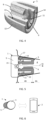
- Fig. 1 illustrates an apparatus according to the present disclosure, comprising an anatomically shaped, compressible cushion member 5 with a first side 5A (to the front) and a second side 5B (to the back) and a channel 6 arranged in the cushion member 5 extending from the first side 5A to the second side 5B for enabling acoustic signal transmission through the cushion member 5, generated e.g. by a speaker 15 such as described below in relation to Fig. 5 .
- the spacer member 8 is configured to provide a minimum clearance C between the opposing side walls 7A, 7B to allow acoustic waves to traverse the channel 6 from the first side 5A to the second side 5B in both a non-compressed state and a compressed state of the cushion member 5.
- the cushion member 5 is made from a flexible and resilient material, such as silicone, and the at least one spacer member 8 is implemented as a reinforcement flange 10 attached to at least one of the second pair of opposing side walls 72.
- the cushion member 5 comprises two reinforcement flanges 10A and 10B, each reinforcement flange 10A or 10B attached one of the second pair of opposing side walls 72 respectively.
- the reinforcement flange(s) 10 are made from a less flexible material than the cushion member 5.
- the cushion member is made from a silicon material with a Shore durometer of 25, and the reinforcement flange is made from more rigid silicon material, preferably ranging between a Shore durometer of 40 and 60.
- the spacer member 8 is arranged to only partially extend between the first side 5A and the second side 5B within the channel 6, thereby allowing for less material to be used to achieve savings of manufacture costs as well as making the structure lighter while still providing sufficient spacing between side walls 7A and 7B.
- the cushion member 5 further comprises a continuous groove 11 arranged within the side walls of the channel 6, in a section of the channel 6 where the spacer member 8 does not extend, to enable flexible adaptation of the cushion member 5 to curved ear canals 4.
- Fig. 5 illustrates an earphone device 1 according to the present disclosure, wherein features that are the same or similar to corresponding features previously described or shown herein are denoted by the same reference numeral as previously used for simplicity.
- the earphone device 1 comprises a housing 3 to be detachably connected to the cushion member 5 of the apparatus at the first side 5A.
- the detachable connection between the housing 3 and the cushion member 5 is a snap-fit connection between a connection groove 14 arranged at the first side 5A of the cushion member 5 and a correspondingly shaped connection rim 17 arranged on the housing 3.
- a "snap-fit connection” refers to an assembly method used to attach flexible parts, usually plastic, to form the final product by pushing the interlocking components of the parts together.
- the cushion member 5 may be adapted to, when fitted into an ear canal 4, substantially fill a cross-section of the ear canal 4, so that the cushion member 5 and the housing 3 is able to, when connected, provide an acoustic sealing between a first portion 4A of the ear canal 4 towards an ear drum and a second portion 4B of the ear canal 4 towards an external environment.
- a speaker 15 may also be arranged in the housing 3 and configured to generate sound waves 16, in response to an audio signal, for delivery through the channel 6 towards the ear canal 4.
- the speaker 7 may comprise a front cavity and a back cavity isolated from the front cavity for optimal sound wave generation.
- a dial such as a volume knob may further be arranged on the housing 3 towards the external environment for adjusting at least one of the overall output level of the speaker 15 or a balance between signal components of the input audio signal.
- the earphone device 1 may further comprise a microphone arranged in the housing 3 and configured to capture sound waves from the direction of the external environment.
- the earphone device 1 may comprise at least two microphones configured to be oriented towards the mouth of a user of the earphone device 1 to enable acoustic beamforming.
- the earphone device 1 may further comprise a voice accelerometer configured to detect presence of the voice of a user of the earphone device 1 via vibrations.
- Additional inputs can generate further input signals that can be used as further components to be mixed in the input audio signal for the speaker 15, or to control other functions of the earphone device 1 (such as de-occlusion).
Landscapes
- Engineering & Computer Science (AREA)
- Physics & Mathematics (AREA)
- Acoustics & Sound (AREA)
- Signal Processing (AREA)
- Manufacturing & Machinery (AREA)
- Headphones And Earphones (AREA)
Claims (14)
- Vorrichtung zum Einsetzen eines Ohrhörergeräts (1) in einen Ohrkanal (4), wobei die Vorrichtung umfasst:• ein anatomisch geformtes komprimierbares Polsterelement (5), das adaptiert ist, um in einen Ohrkanal (4) zu passen;• einen Kanal (6), der in dem Polsterelement (5) angeordnet ist und sich von einer ersten Seite (5A) zu einer zweiten Seite (5B) erstreckt, wobei der Kanal (6) mindestens zwei gegenüber liegende Seitenwände (7A, 7B) umfasst,∘ wobei das Polsterelement (5) und der Kanal (6) oval geformt sind, wobei der Kanal (6) ein erstes Paar gegenüber liegender Seitenwände (71), definiert durch eine kleinere Krümmung, und ein zweites Paar gegenüber liegender Seitenwände (72), definiert durch eine größere Krümmung, umfasst;• mindestens ein Abstandhalterelement (8), das sich von mindestens einer der Seitenwände (7B) in Richtung einer gegenüber liegenden Seitenwand (7A) erstreckt, jedoch nicht mit der gegenüber liegenden Seitenwand (7A) verbunden ist,∘ wobei das mindestens eine Abstandhalterelement (8) ausgestaltet ist, um einen minimalen Freiraum (C) zwischen den gegenüber liegenden Seitenwänden (7A, 7B) bereitzustellen, um zu ermöglichen, dass Schallwellen den Kanal (6) von der ersten Seite (5A) zu der zweiten Seite (5B) sowohl im nicht-komprimierten Zustand als auch im komprimierten Zustand des Polsterelements (5) durchqueren.
- Vorrichtung nach Anspruch 1, wobei das mindestens eine Abstandhalterelement (8) einen Höcker (9) umfasst, der aus einem von dem ersten Paar gegenüber liegender Seitenwände (71) vorspringt, wobei der Höcker (9) homogen mit dem Polsterelement (5) ist.
- Vorrichtung nach Anspruch 2, wobei das mindestens eine Abstandhalterelement (8) zwei Höcker (9A, 9B) umfasst, wobei jeder Höcker (9A/9B) jeweils von einem von dem ersten Paar gegenüber liegender Seitenwände (71) vorspringt.
- Vorrichtung nach einem der Ansprüche 1 bis 3, wobei das Polsterelement (5) aus einem flexiblen und nachgiebigen Material gefertigt ist, wie Silikon, und wobei das mindestens eine Abstandhalterelement (8) einen Verstärkungsflansch (10) umfasst, der an mindestens einem von dem zweiten Paar gegenüber liegender Seitenwände (72) angebracht ist, wobei der Verstärkungsflansch (10) aus weniger flexiblem Material als das Polsterelement (5) gefertigt ist.
- Vorrichtung nach Anspruch 4, wobei das mindestens eine Abstandhalterelement (8) zwei Verstärkungsflansche (10A, 10B) umfasst, wobei jeder Verstärkungsflansch (10A/10B) jeweils an einem von dem zweiten Paar gegenüber liegender Seitenwände (72) angebracht ist.
- Vorrichtung nach einem der Ansprüche 1 bis 5, wobei das Abstandhalterelement (8) so angeordnet ist, dass es sich nur teilweise zwischen der ersten Seite (5A) und der zweiten Seite (SB) innerhalb des Kanals (6) erstreckt; und wobei das Polsterelement (5) des Weiteren eine durchgehende Rille (11) aufweist, die innerhalb der Seitenwände des Kanals (6) in einem Abschnitt des Kanals (6) angeordnet ist, wo sich das Abstandhalterelement (8) nicht erstreckt, um flexible Adaptierung des Polsterelements (5) an gekrümmte Ohrkanäle (4) zu ermöglichen.
- Vorrichtung nach einem der Ansprüche 1 bis 6, wobei das Polsterelement (5) einen länglichen Hohlkörper (12) mit einem eingeschlossenen Körperhohlraum (13) umfasst, der den Kanal (6) umgibt, wodurch zusätzliche Biegeflexibilität und Komprimierbarkeit bereitgestellt werden.
- Vorrichtung nach Anspruch 7, wobei der Körperhohlraum (13) zu einer Seite (5A/5B) des Polsterelements (5) offen ist, um eine Verbindungsrille (14) zum Verbinden mit einem Ohrhörergehäuse (3) bereitzustellen.
- Vorrichtung nach einem der Ansprüche 1 bis 8, wobei das Polsterelement (5) und das Abstandhalterelement (8) so ausgestaltet sind, dassder minimale Freiraum (C) zwischen den gegenüber liegenden Seitenwänden (7A, 7B) in einem komprimierten Zustand im Bereich zwischen 1 und 1,5 mm liegt;eine kleinste Gesamtbreite des Polsterelements (5), gemessen in dem komprimierten Zustand, 3,5 mm beträgt; undeine kleinste Querschnittfläche des Kanals (6), gemessen im komprimierten Zustand, 5 mm2 beträgt.
- Ohrhörergerät (1), umfassend:eine Vorrichtung nach einem der Ansprüche 1 bis 9;ein Gehäuse (3), das adaptiert ist, um abnehmbar mit dem Polsterelement (5) der Vorrichtung an der ersten Seite (5A) verbunden zu werden; undeinen Lautsprecher (15), der in dem Gehäuse (3) angeordnet ist und ausgestaltet ist, um in Reaktion auf ein Audiosignal Schallwellen (16) zur Abgabe durch den Kanal (6) hindurch in Richtung des Ohrkanals (4) zu generieren.
- Ohrhörergerät (1) nach Anspruch 10, wobei die abnehmbare Verbindung zwischen dem Gehäuse (3) und dem Polsterelement (5) eine Einrastverbindung zwischen einer Verbindungsrille (14), die an der ersten Seite (5A) des Polsterelements (5) angeordnet ist, und einem entsprechend geformten Verbindungskranz (17) ist, der auf dem Gehäuse (3) angeordnet ist.
- Ohrhörergerät (1) nach einem der Ansprüche 10 oder 11, wobei das Polsterelement (5) adaptiert ist, um, wenn es in einen Ohrkanal (4) eingesetzt ist, einen Querschnitt des Ohrkanals (4) im Wesentlichen auszufüllen; und wobei das Polsterelement (5) und das Gehäuse (3) so angeordnet sind, dass sie, wenn sie verbunden sind, eine akustische Abdichtung zwischen einem ersten Anteil (4A) des Ohrkanals (4) in Richtung eines Trommelfells und einem zweiten Anteil (4B) des Ohrkanals (4) in Richtung einer äußeren Umgebung bereitstellen.
- System, umfassend:mindestens ein Ohrhörergerät (1) nach einem der Ansprüche 10 bis 12; undein Host-Gerät (2), das in Datenverbindung mit dem mindestens einen Ohrhörergerät (1) angeordnet ist und ausgestaltet ist, um das Audiosignal zur Abgabe an den Lautsprecher (15) mittels der Datenverbindung zu generieren.
- System nach Anspruch 13, wobeidas Ohrhörergerät (1) ein "True Wireless Stereo"-, TWS-, Headset ist,das Host-Gerät (2) ein mobiles Smartphone ist, unddie Datenverbindung unter Verwendung eines Bluetooth-Protokolls hergestellt wird.
Applications Claiming Priority (1)
| Application Number | Priority Date | Filing Date | Title |
|---|---|---|---|
| PCT/EP2020/052598 WO2021155900A1 (en) | 2020-02-03 | 2020-02-03 | Adaptive eartip for true wireless stereo headsets |
Publications (2)
| Publication Number | Publication Date |
|---|---|
| EP4070566A1 EP4070566A1 (de) | 2022-10-12 |
| EP4070566B1 true EP4070566B1 (de) | 2024-09-25 |
Family
ID=69467546
Family Applications (1)
| Application Number | Title | Priority Date | Filing Date |
|---|---|---|---|
| EP20703441.4A Active EP4070566B1 (de) | 2020-02-03 | 2020-02-03 | Adaptiver ohrstöpsel für wirklich schnurlose stereo-headsets |
Country Status (5)
| Country | Link |
|---|---|
| US (1) | US12047725B2 (de) |
| EP (1) | EP4070566B1 (de) |
| JP (1) | JP7544827B2 (de) |
| CN (1) | CN115039416B (de) |
| WO (1) | WO2021155900A1 (de) |
Families Citing this family (1)
| Publication number | Priority date | Publication date | Assignee | Title |
|---|---|---|---|---|
| CN214544720U (zh) * | 2021-03-09 | 2021-10-29 | 歌尔科技有限公司 | 一种耳罩和一种头戴式耳机 |
Family Cites Families (24)
| Publication number | Priority date | Publication date | Assignee | Title |
|---|---|---|---|---|
| JPS4742593Y1 (de) * | 1969-04-03 | 1972-12-23 | ||
| US5631965A (en) * | 1992-06-19 | 1997-05-20 | Chang; Joseph S. | Hearing protector |
| US6359993B2 (en) * | 1999-01-15 | 2002-03-19 | Sonic Innovations | Conformal tip for a hearing aid with integrated vent and retrieval cord |
| US20060042867A1 (en) * | 2004-08-25 | 2006-03-02 | Phonak Ag | Hearing protection earplug and method for manufacturing such an earplug |
| US7478702B2 (en) * | 2004-08-25 | 2009-01-20 | Phonak Ag | Customized hearing protection earplug and method for manufacturing the same |
| JP4742593B2 (ja) | 2005-01-19 | 2011-08-10 | 株式会社デンソー | 圧力検出装置の製造方法 |
| US8447059B2 (en) * | 2007-10-31 | 2013-05-21 | Thx Ltd | Earphone device |
| WO2009086555A1 (en) * | 2007-12-31 | 2009-07-09 | Koss Corporation | Adjustable shape earphone |
| US9826322B2 (en) * | 2009-07-22 | 2017-11-21 | Eargo, Inc. | Adjustable securing mechanism |
| US10097936B2 (en) * | 2009-07-22 | 2018-10-09 | Eargo, Inc. | Adjustable securing mechanism |
| US20110268308A1 (en) * | 2010-04-30 | 2011-11-03 | Rafael Vasquez | Partially Occluding Ergonomic Earbud Adapter |
| US8348011B1 (en) * | 2011-08-05 | 2013-01-08 | Rextec International Limited | Earplug cushion for an earphone |
| US8848964B2 (en) | 2011-12-22 | 2014-09-30 | Tammy Erdel | Audio-bypass, safety earbud apparatus and method |
| US20140166388A1 (en) * | 2012-12-17 | 2014-06-19 | Cotron Corporation | Ear tip |
| JP2015005790A (ja) | 2013-06-19 | 2015-01-08 | 賢太 田中 | イヤホン装置 |
| US9088846B2 (en) | 2013-08-14 | 2015-07-21 | Klipsch Group, Inc. | Oval variable wall earbud |
| JP6111944B2 (ja) * | 2013-09-12 | 2017-04-12 | 株式会社Jvcケンウッド | イヤーピース及びそれを備えたイヤホン |
| US9232304B2 (en) * | 2013-12-20 | 2016-01-05 | 3M Innovative Properties Company | Ear canal sealing stethoscope ear tips |
| EP2930944A1 (de) * | 2014-04-07 | 2015-10-14 | Oticon A/s | Hörgerät mit einem flexiblen Verbindungselement |
| US9729953B2 (en) * | 2015-07-24 | 2017-08-08 | Logitech Europe S.A. | Wearable earbuds having a reduced tip dimension |
| US10057675B2 (en) * | 2015-07-29 | 2018-08-21 | Bose Corporation | Integration of sensors into earphones |
| DE102016011422A1 (de) | 2015-09-22 | 2017-03-23 | Christoph Schmieg | Kappe zur Positionierung im Gehörgang eines Ohres und Kopfhörer |
| EP3463231A1 (de) * | 2016-05-26 | 2019-04-10 | Flare Audio Technologies Limited | Ohrenschutzvorrichtung |
| KR101899005B1 (ko) * | 2016-12-05 | 2018-09-14 | 주식회사 사운드브릿지 | 외부 마이크 및 이어커낼 마이크가 내장된 외부 소음환경 적응형 블루투스 이어셋 및 이의 제어방법 |
-
2020
- 2020-02-03 WO PCT/EP2020/052598 patent/WO2021155900A1/en not_active Ceased
- 2020-02-03 CN CN202080095233.8A patent/CN115039416B/zh active Active
- 2020-02-03 JP JP2022547137A patent/JP7544827B2/ja active Active
- 2020-02-03 US US17/793,843 patent/US12047725B2/en active Active
- 2020-02-03 EP EP20703441.4A patent/EP4070566B1/de active Active
Also Published As
| Publication number | Publication date |
|---|---|
| WO2021155900A1 (en) | 2021-08-12 |
| JP2023514124A (ja) | 2023-04-05 |
| EP4070566A1 (de) | 2022-10-12 |
| US20230049385A1 (en) | 2023-02-16 |
| CN115039416A (zh) | 2022-09-09 |
| US12047725B2 (en) | 2024-07-23 |
| JP7544827B2 (ja) | 2024-09-03 |
| CN115039416B (zh) | 2025-10-24 |
Similar Documents
| Publication | Publication Date | Title |
|---|---|---|
| US11146877B2 (en) | Sound output device and sound guiding device | |
| CN105307066B (zh) | 单声道无线耳机 | |
| CN109889937B (zh) | 具有符合人体工学软垫的耳机设备 | |
| US10231048B2 (en) | Ergonomic earpiece with attachment mount | |
| US9813794B2 (en) | Noise reduction with in-ear headphone | |
| CN108605178B (zh) | 耳机中的压力均衡 | |
| US6810987B1 (en) | Earbud headset | |
| US8189846B2 (en) | Vented in-the-ear headphone | |
| US10791390B2 (en) | Flex-fit ear tip for headphones | |
| US10142735B2 (en) | Dual mode headphone and method therefor | |
| CN104066024A (zh) | 耳机 | |
| EP4070566B1 (de) | Adaptiver ohrstöpsel für wirklich schnurlose stereo-headsets | |
| CN211128133U (zh) | 入耳式耳机 | |
| CN117412212B (zh) | 一种耳屏内侧混合传导耳机装置及其设计方法 | |
| WO2022116765A1 (zh) | 一种耳机及移动终端 |
Legal Events
| Date | Code | Title | Description |
|---|---|---|---|
| STAA | Information on the status of an ep patent application or granted ep patent |
Free format text: STATUS: UNKNOWN |
|
| STAA | Information on the status of an ep patent application or granted ep patent |
Free format text: STATUS: THE INTERNATIONAL PUBLICATION HAS BEEN MADE |
|
| PUAI | Public reference made under article 153(3) epc to a published international application that has entered the european phase |
Free format text: ORIGINAL CODE: 0009012 |
|
| STAA | Information on the status of an ep patent application or granted ep patent |
Free format text: STATUS: REQUEST FOR EXAMINATION WAS MADE |
|
| 17P | Request for examination filed |
Effective date: 20220704 |
|
| AK | Designated contracting states |
Kind code of ref document: A1 Designated state(s): AL AT BE BG CH CY CZ DE DK EE ES FI FR GB GR HR HU IE IS IT LI LT LU LV MC MK MT NL NO PL PT RO RS SE SI SK SM TR |
|
| DAV | Request for validation of the european patent (deleted) | ||
| DAX | Request for extension of the european patent (deleted) | ||
| GRAP | Despatch of communication of intention to grant a patent |
Free format text: ORIGINAL CODE: EPIDOSNIGR1 |
|
| STAA | Information on the status of an ep patent application or granted ep patent |
Free format text: STATUS: GRANT OF PATENT IS INTENDED |
|
| INTG | Intention to grant announced |
Effective date: 20240531 |
|
| GRAS | Grant fee paid |
Free format text: ORIGINAL CODE: EPIDOSNIGR3 |
|
| GRAA | (expected) grant |
Free format text: ORIGINAL CODE: 0009210 |
|
| STAA | Information on the status of an ep patent application or granted ep patent |
Free format text: STATUS: THE PATENT HAS BEEN GRANTED |
|
| AK | Designated contracting states |
Kind code of ref document: B1 Designated state(s): AL AT BE BG CH CY CZ DE DK EE ES FI FR GB GR HR HU IE IS IT LI LT LU LV MC MK MT NL NO PL PT RO RS SE SI SK SM TR |
|
| REG | Reference to a national code |
Ref country code: GB Ref legal event code: FG4D |
|
| REG | Reference to a national code |
Ref country code: CH Ref legal event code: EP |
|
| REG | Reference to a national code |
Ref country code: DE Ref legal event code: R096 Ref document number: 602020038257 Country of ref document: DE |
|
| REG | Reference to a national code |
Ref country code: IE Ref legal event code: FG4D |
|
| REG | Reference to a national code |
Ref country code: NL Ref legal event code: FP |
|
| REG | Reference to a national code |
Ref country code: LT Ref legal event code: MG9D |
|
| PG25 | Lapsed in a contracting state [announced via postgrant information from national office to epo] |
Ref country code: NO Free format text: LAPSE BECAUSE OF FAILURE TO SUBMIT A TRANSLATION OF THE DESCRIPTION OR TO PAY THE FEE WITHIN THE PRESCRIBED TIME-LIMIT Effective date: 20241225 |
|
| PG25 | Lapsed in a contracting state [announced via postgrant information from national office to epo] |
Ref country code: GR Free format text: LAPSE BECAUSE OF FAILURE TO SUBMIT A TRANSLATION OF THE DESCRIPTION OR TO PAY THE FEE WITHIN THE PRESCRIBED TIME-LIMIT Effective date: 20241226 Ref country code: FI Free format text: LAPSE BECAUSE OF FAILURE TO SUBMIT A TRANSLATION OF THE DESCRIPTION OR TO PAY THE FEE WITHIN THE PRESCRIBED TIME-LIMIT Effective date: 20240925 |
|
| PG25 | Lapsed in a contracting state [announced via postgrant information from national office to epo] |
Ref country code: BG Free format text: LAPSE BECAUSE OF FAILURE TO SUBMIT A TRANSLATION OF THE DESCRIPTION OR TO PAY THE FEE WITHIN THE PRESCRIBED TIME-LIMIT Effective date: 20240925 |
|
| PG25 | Lapsed in a contracting state [announced via postgrant information from national office to epo] |
Ref country code: LV Free format text: LAPSE BECAUSE OF FAILURE TO SUBMIT A TRANSLATION OF THE DESCRIPTION OR TO PAY THE FEE WITHIN THE PRESCRIBED TIME-LIMIT Effective date: 20240925 |
|
| PG25 | Lapsed in a contracting state [announced via postgrant information from national office to epo] |
Ref country code: RS Free format text: LAPSE BECAUSE OF FAILURE TO SUBMIT A TRANSLATION OF THE DESCRIPTION OR TO PAY THE FEE WITHIN THE PRESCRIBED TIME-LIMIT Effective date: 20241225 |
|
| PG25 | Lapsed in a contracting state [announced via postgrant information from national office to epo] |
Ref country code: RS Free format text: LAPSE BECAUSE OF FAILURE TO SUBMIT A TRANSLATION OF THE DESCRIPTION OR TO PAY THE FEE WITHIN THE PRESCRIBED TIME-LIMIT Effective date: 20241225 Ref country code: NO Free format text: LAPSE BECAUSE OF FAILURE TO SUBMIT A TRANSLATION OF THE DESCRIPTION OR TO PAY THE FEE WITHIN THE PRESCRIBED TIME-LIMIT Effective date: 20241225 Ref country code: LV Free format text: LAPSE BECAUSE OF FAILURE TO SUBMIT A TRANSLATION OF THE DESCRIPTION OR TO PAY THE FEE WITHIN THE PRESCRIBED TIME-LIMIT Effective date: 20240925 Ref country code: GR Free format text: LAPSE BECAUSE OF FAILURE TO SUBMIT A TRANSLATION OF THE DESCRIPTION OR TO PAY THE FEE WITHIN THE PRESCRIBED TIME-LIMIT Effective date: 20241226 Ref country code: FI Free format text: LAPSE BECAUSE OF FAILURE TO SUBMIT A TRANSLATION OF THE DESCRIPTION OR TO PAY THE FEE WITHIN THE PRESCRIBED TIME-LIMIT Effective date: 20240925 Ref country code: BG Free format text: LAPSE BECAUSE OF FAILURE TO SUBMIT A TRANSLATION OF THE DESCRIPTION OR TO PAY THE FEE WITHIN THE PRESCRIBED TIME-LIMIT Effective date: 20240925 |
|
| REG | Reference to a national code |
Ref country code: AT Ref legal event code: MK05 Ref document number: 1727665 Country of ref document: AT Kind code of ref document: T Effective date: 20240925 |
|
| PG25 | Lapsed in a contracting state [announced via postgrant information from national office to epo] |
Ref country code: PT Free format text: LAPSE BECAUSE OF FAILURE TO SUBMIT A TRANSLATION OF THE DESCRIPTION OR TO PAY THE FEE WITHIN THE PRESCRIBED TIME-LIMIT Effective date: 20250127 Ref country code: IS Free format text: LAPSE BECAUSE OF FAILURE TO SUBMIT A TRANSLATION OF THE DESCRIPTION OR TO PAY THE FEE WITHIN THE PRESCRIBED TIME-LIMIT Effective date: 20250125 |
|
| PG25 | Lapsed in a contracting state [announced via postgrant information from national office to epo] |
Ref country code: RO Free format text: LAPSE BECAUSE OF FAILURE TO SUBMIT A TRANSLATION OF THE DESCRIPTION OR TO PAY THE FEE WITHIN THE PRESCRIBED TIME-LIMIT Effective date: 20240925 Ref country code: SM Free format text: LAPSE BECAUSE OF FAILURE TO SUBMIT A TRANSLATION OF THE DESCRIPTION OR TO PAY THE FEE WITHIN THE PRESCRIBED TIME-LIMIT Effective date: 20240925 |
|
| PG25 | Lapsed in a contracting state [announced via postgrant information from national office to epo] |
Ref country code: ES Free format text: LAPSE BECAUSE OF FAILURE TO SUBMIT A TRANSLATION OF THE DESCRIPTION OR TO PAY THE FEE WITHIN THE PRESCRIBED TIME-LIMIT Effective date: 20240925 |
|
| PG25 | Lapsed in a contracting state [announced via postgrant information from national office to epo] |
Ref country code: AT Free format text: LAPSE BECAUSE OF FAILURE TO SUBMIT A TRANSLATION OF THE DESCRIPTION OR TO PAY THE FEE WITHIN THE PRESCRIBED TIME-LIMIT Effective date: 20240925 Ref country code: EE Free format text: LAPSE BECAUSE OF FAILURE TO SUBMIT A TRANSLATION OF THE DESCRIPTION OR TO PAY THE FEE WITHIN THE PRESCRIBED TIME-LIMIT Effective date: 20240925 |
|
| PG25 | Lapsed in a contracting state [announced via postgrant information from national office to epo] |
Ref country code: PL Free format text: LAPSE BECAUSE OF FAILURE TO SUBMIT A TRANSLATION OF THE DESCRIPTION OR TO PAY THE FEE WITHIN THE PRESCRIBED TIME-LIMIT Effective date: 20240925 Ref country code: CZ Free format text: LAPSE BECAUSE OF FAILURE TO SUBMIT A TRANSLATION OF THE DESCRIPTION OR TO PAY THE FEE WITHIN THE PRESCRIBED TIME-LIMIT Effective date: 20240925 |
|
| PG25 | Lapsed in a contracting state [announced via postgrant information from national office to epo] |
Ref country code: IT Free format text: LAPSE BECAUSE OF FAILURE TO SUBMIT A TRANSLATION OF THE DESCRIPTION OR TO PAY THE FEE WITHIN THE PRESCRIBED TIME-LIMIT Effective date: 20240925 Ref country code: SK Free format text: LAPSE BECAUSE OF FAILURE TO SUBMIT A TRANSLATION OF THE DESCRIPTION OR TO PAY THE FEE WITHIN THE PRESCRIBED TIME-LIMIT Effective date: 20240925 |
|
| REG | Reference to a national code |
Ref country code: DE Ref legal event code: R097 Ref document number: 602020038257 Country of ref document: DE |
|
| PG25 | Lapsed in a contracting state [announced via postgrant information from national office to epo] |
Ref country code: DK Free format text: LAPSE BECAUSE OF FAILURE TO SUBMIT A TRANSLATION OF THE DESCRIPTION OR TO PAY THE FEE WITHIN THE PRESCRIBED TIME-LIMIT Effective date: 20240925 |
|
| PLBE | No opposition filed within time limit |
Free format text: ORIGINAL CODE: 0009261 |
|
| STAA | Information on the status of an ep patent application or granted ep patent |
Free format text: STATUS: NO OPPOSITION FILED WITHIN TIME LIMIT |
|
| 26N | No opposition filed |
Effective date: 20250626 |
|
| PG25 | Lapsed in a contracting state [announced via postgrant information from national office to epo] |
Ref country code: SE Free format text: LAPSE BECAUSE OF FAILURE TO SUBMIT A TRANSLATION OF THE DESCRIPTION OR TO PAY THE FEE WITHIN THE PRESCRIBED TIME-LIMIT Effective date: 20240925 |
|
| PG25 | Lapsed in a contracting state [announced via postgrant information from national office to epo] |
Ref country code: MC Free format text: LAPSE BECAUSE OF FAILURE TO SUBMIT A TRANSLATION OF THE DESCRIPTION OR TO PAY THE FEE WITHIN THE PRESCRIBED TIME-LIMIT Effective date: 20240925 |
|
| REG | Reference to a national code |
Ref country code: CH Ref legal event code: PL |
|
| PG25 | Lapsed in a contracting state [announced via postgrant information from national office to epo] |
Ref country code: LU Free format text: LAPSE BECAUSE OF NON-PAYMENT OF DUE FEES Effective date: 20250203 |
|
| PG25 | Lapsed in a contracting state [announced via postgrant information from national office to epo] |
Ref country code: CH Free format text: LAPSE BECAUSE OF NON-PAYMENT OF DUE FEES Effective date: 20250228 |
|
| GBPC | Gb: european patent ceased through non-payment of renewal fee |
Effective date: 20250203 |
|
| REG | Reference to a national code |
Ref country code: BE Ref legal event code: MM Effective date: 20250228 |
|
| PG25 | Lapsed in a contracting state [announced via postgrant information from national office to epo] |
Ref country code: GB Free format text: LAPSE BECAUSE OF NON-PAYMENT OF DUE FEES Effective date: 20250203 |
|
| PG25 | Lapsed in a contracting state [announced via postgrant information from national office to epo] |
Ref country code: HR Free format text: LAPSE BECAUSE OF FAILURE TO SUBMIT A TRANSLATION OF THE DESCRIPTION OR TO PAY THE FEE WITHIN THE PRESCRIBED TIME-LIMIT Effective date: 20240925 Ref country code: FR Free format text: LAPSE BECAUSE OF NON-PAYMENT OF DUE FEES Effective date: 20250228 |
|
| PG25 | Lapsed in a contracting state [announced via postgrant information from national office to epo] |
Ref country code: BE Free format text: LAPSE BECAUSE OF NON-PAYMENT OF DUE FEES Effective date: 20250228 |
|
| PG25 | Lapsed in a contracting state [announced via postgrant information from national office to epo] |
Ref country code: IE Free format text: LAPSE BECAUSE OF NON-PAYMENT OF DUE FEES Effective date: 20250203 |
|
| PGFP | Annual fee paid to national office [announced via postgrant information from national office to epo] |
Ref country code: NL Payment date: 20260106 Year of fee payment: 7 |
|
| PGFP | Annual fee paid to national office [announced via postgrant information from national office to epo] |
Ref country code: DE Payment date: 20251230 Year of fee payment: 7 |