EP4070101B1 - Strip holder - Google Patents
Strip holder Download PDFInfo
- Publication number
- EP4070101B1 EP4070101B1 EP20734965.5A EP20734965A EP4070101B1 EP 4070101 B1 EP4070101 B1 EP 4070101B1 EP 20734965 A EP20734965 A EP 20734965A EP 4070101 B1 EP4070101 B1 EP 4070101B1
- Authority
- EP
- European Patent Office
- Prior art keywords
- strip
- strip holder
- fluid
- holder
- receiving channel
- Prior art date
- Legal status (The legal status is an assumption and is not a legal conclusion. Google has not performed a legal analysis and makes no representation as to the accuracy of the status listed.)
- Active
Links
Images
Classifications
-
- G—PHYSICS
- G01—MEASURING; TESTING
- G01N—INVESTIGATING OR ANALYSING MATERIALS BY DETERMINING THEIR CHEMICAL OR PHYSICAL PROPERTIES
- G01N33/00—Investigating or analysing materials by specific methods not covered by groups G01N1/00 - G01N31/00
- G01N33/48—Biological material, e.g. blood, urine; Haemocytometers
- G01N33/50—Chemical analysis of biological material, e.g. blood, urine; Testing involving biospecific ligand binding methods; Immunological testing
- G01N33/53—Immunoassay; Biospecific binding assay; Materials therefor
- G01N33/5302—Apparatus specially adapted for immunological test procedures
-
- B—PERFORMING OPERATIONS; TRANSPORTING
- B01—PHYSICAL OR CHEMICAL PROCESSES OR APPARATUS IN GENERAL
- B01L—CHEMICAL OR PHYSICAL LABORATORY APPARATUS FOR GENERAL USE
- B01L3/00—Containers or dishes for laboratory use, e.g. laboratory glassware; Droppers
- B01L3/50—Containers for the purpose of retaining a material to be analysed, e.g. test tubes
- B01L3/502—Containers for the purpose of retaining a material to be analysed, e.g. test tubes with fluid transport, e.g. in multi-compartment structures
- B01L3/5023—Containers for the purpose of retaining a material to be analysed, e.g. test tubes with fluid transport, e.g. in multi-compartment structures with a sample being transported to, and subsequently stored in an absorbent for analysis
-
- G—PHYSICS
- G01—MEASURING; TESTING
- G01N—INVESTIGATING OR ANALYSING MATERIALS BY DETERMINING THEIR CHEMICAL OR PHYSICAL PROPERTIES
- G01N25/00—Investigating or analyzing materials by the use of thermal means
- G01N25/20—Investigating or analyzing materials by the use of thermal means by investigating the development of heat, i.e. calorimetry, e.g. by measuring specific heat, by measuring thermal conductivity
-
- G—PHYSICS
- G01—MEASURING; TESTING
- G01N—INVESTIGATING OR ANALYSING MATERIALS BY DETERMINING THEIR CHEMICAL OR PHYSICAL PROPERTIES
- G01N33/00—Investigating or analysing materials by specific methods not covered by groups G01N1/00 - G01N31/00
- G01N33/48—Biological material, e.g. blood, urine; Haemocytometers
- G01N33/483—Physical analysis of biological material
- G01N33/487—Physical analysis of biological material of liquid biological material
- G01N33/4875—Details of handling test elements, e.g. dispensing or storage, not specific to a particular test method
-
- B—PERFORMING OPERATIONS; TRANSPORTING
- B01—PHYSICAL OR CHEMICAL PROCESSES OR APPARATUS IN GENERAL
- B01L—CHEMICAL OR PHYSICAL LABORATORY APPARATUS FOR GENERAL USE
- B01L2200/00—Solutions for specific problems relating to chemical or physical laboratory apparatus
- B01L2200/06—Fluid handling related problems
- B01L2200/0684—Venting, avoiding backpressure, avoid gas bubbles
-
- B—PERFORMING OPERATIONS; TRANSPORTING
- B01—PHYSICAL OR CHEMICAL PROCESSES OR APPARATUS IN GENERAL
- B01L—CHEMICAL OR PHYSICAL LABORATORY APPARATUS FOR GENERAL USE
- B01L2200/00—Solutions for specific problems relating to chemical or physical laboratory apparatus
- B01L2200/16—Reagents, handling or storing thereof
-
- B—PERFORMING OPERATIONS; TRANSPORTING
- B01—PHYSICAL OR CHEMICAL PROCESSES OR APPARATUS IN GENERAL
- B01L—CHEMICAL OR PHYSICAL LABORATORY APPARATUS FOR GENERAL USE
- B01L2300/00—Additional constructional details
- B01L2300/08—Geometry, shape and general structure
- B01L2300/0809—Geometry, shape and general structure rectangular shaped
- B01L2300/0825—Test strips
Definitions
- the present invention relates to a strip holder consisting of a housing with a front side and a back side, wherein the housing comprises at least one strip receiving channel, at least one fluid receiving channel, and at least one fluid reservoir, wherein the at least one strip receiving channel and the at least one fluid receiving channel are in fluid connection with the at least one fluid reservoir, and wherein the front side is made of a solid material and comprises at least one inspection window.
- the present invention further relates to a use of the strip holder, as well as a kit comprising the strip holder.
- Lateral flow immunoassays also referred to as lateral flow immunochromatographic assays or lateral flow tests, are an easy-to-use tool to evaluate the presence or absence and in some cases also the quantity of an analyte-of-interest in a sample.
- a lateral flow test strip is a membrane-based carrier, which comprises at least a sample loading zone, a conjugate pad and a test zone.
- the conjugate pad comprises labeled binding agents, often labeled antibodies, which can bind specifically to an analyte-of-interest.
- the test zone comprises immobilized un-labeled binding agents, which can also bind specifically the analyte-of-interest.
- a lateral flow test strip further comprises a control zone, comprising immobilized un-labeled binding agents which can bind the labeled binding agents.
- Via detection of the label in the test zone a conclusion on the presence or absence of the analyte in the sample fluid can be drawn. Examples of lateral flow tests are disclosed e.g. in Koczula and Gallotta. Essays Biochem. 2016 Jun 30;60(1):111-20 or in Krska and Molinelli. Anal Bioanal Chem. 2009 Jan;393(1):67-71 .
- the binding agents of a lateral flow test strip can be adapted to specifically bind to a large number of different analytes.
- lateral flow tests offer very broad applicability and are routinely used in many fields such as environmental testing, evaluation assays of human, animal and plant health, food and feed testing etc.
- Lateral flow tests are performed not only by technical professionals in laboratory use but also by untrained personnel and individuals, e.g. in home testings, point-of-care testings etc.
- a lateral flow test can be performed using solely a test strip and a sample fluid.
- more advanced lateral flow test setups can be provided.
- strip holders or casings can provide features of convenience such as protection of the test strip or the sample, and operating guidance for the intended user.
- strip holders can be found in literature, e.g. in the form of a cartridge assembly as described in WO 2018/125271 A1 .
- the cartridge assembly disclosed in WO 2018/125271 A1 comprises at least a base portion and a removably connected cap portion, wherein a flange of the base portion has to be disposed in the cap portion to allow forming of a fluid-flow passage.
- fluid can be introduced into the base portion, which fluid is guided further into the cap portion via a fluid-flow passage of the flange of the cap portion and an optional additional fluid filter structure to ultimately arrive in a fluid receiving void of the cap portion where the fluid may contact a test strip.
- a cartridge assembly setup can be expected to be well-suited for certain assays and might even be transferred e.g. in an incubator oven to achieve a controlled temperature, the specific arrangement of the individual components required for the disclosed cartridge assembly would not allow fast, efficient and even heat transfer from an external temperature source to the test strip and the sample fluid inside the cartridge assembly.
- the cartridge assembly of WO 2018/125271 A1 lacks solutions to deal with mistakenly added excess fluid.
- Other examples may be in the form of an insert cassette for an assay reader as described in WO 2009/038798 , or as module part of a reader apparatus as described in US 9,008,373 B2 .
- strip holders are described wherein a strip is enclosed in a receiving well within a plastic strip holder casing or cassette, consisting of a top element and a bottom element, which elements are mated to form the casing.
- a sample fluid may be applied onto such an enclosed strip via an application port.
- a bar or plate element is described to contact the strip, which bar or plate element is made of a different material than the plastic strip holder casing or cassette.
- the bar or plate element is described to be made of a metal such as copper, gold, silver, aluminum or metal alloys.
- Such strip holders are designed for single-use only and cannot be re-used due to the irreversible enclosure of the strip inside the casing.
- a strip holder according to the present invention is a strip holder consisting of a housing with a front side and a back side, wherein the housing comprises at least one strip receiving channel, at least one fluid receiving channel, and at least one fluid reservoir,
- the strip holder described above may be a strip holder that can be further characterized in that the back side of the housing is an essentially flat surface; and in that the back side of the housing is thermally conductive.
- any channel structure that can accommodate a typical lateral flow assay strip can be a strip receiving channel.
- Any channel structure that allows a flow of liquids from one opening of the channel to the other can be a fluid receiving channel.
- the terms “liquid” and “fluid” are used interchangeably.
- the fluid receiving channel is the same channel structure as the strip receiving channel.
- in fluid connection means that a fluid may pass from one component to the other. For instance, when a channel and a reservoir are in fluid connection, it is possible to pour a fluid through the channel into the reservoir.
- Any structure that is in fluid connection with a fluid receiving channel and that can hold a defined amount of liquid in a strip holder can be a fluid reservoir.
- a fluid reservoir can have the same, smaller or larger width dimensions as/than a fluid receiving channel.
- An inspection window as referred to herein is a structure that allows viewing of at least one test strip inserted into a strip holder from the outside, in particular viewing of the test zone, and the additional control zone of the test strip if available.
- An inspection window can be a recess or a cut-out or an opening in the housing, through which the test zone and the optionally available control zone on a test strip inserted into a strip holder can be inspected.
- An inspection window can also be implemented by using a see-through material on the strip holder housing, such as transparent foil materials or glass.
- a surface is considered an essentially flat surface when no surface irregularities are observable on a macroscopic scale, i.e. no surface irregularities can be observed with the naked eye.
- a thermally conductive back side as referred to herein, can be defined by its specific heat transfer index.
- a thermally conductive back side can be any back side with a specific heat transfer index of at least 0.0167 s -1 , preferably of at least 0.02 s -1 , preferably of at least 0.03 s -1 , more preferably of at least 0.05 s -1 , more preferably of at least 0.075 s -1 , most preferably of at least 0.08 s -1 .
- the specific heat transfer index of a back side can be determined experimentally by calculating the reciprocal of the time in seconds required to achieve a temperature transfer of 10 °C from 25 °C to 35 °C from the outside of the back side of a strip holder housing to the inside of the back side of the strip holder housing.
- the thickness of the back side of the strip holder is between 0.001 and 1.5 mm, more preferably between 0.001 and 1.2 mm, even more preferably between 0.01 and 1 mm, even more preferably between 0.015 and 0.8 mm, most preferably between 0.03 and 0.7 mm.
- a person skilled in the art is aware of the fact that the specific heat transfer index of a back side of a strip holder depends on the material as well as on the thickness of the back side.
- the specific heat transfer index of a certain back side of a strip holder shall be determined by placing a thermometer inside of a strip holder with the back side to be tested, and placing said strip holder onto a thermal element.
- a thermal element is essentially a surface that can be hold at a chosen temperature, such as one from a laboratory hotplate, whereby the back side of the strip holder contacts the hotplate surface.
- the temperature in the inside of the strip holder is measured at regular time points as soon as the strip holder is contacted with the hotplate surface.
- a laboratory hotplate is set to 45 °C and the strip holder with the back side to be tested is contacted with this hotplate as described above. Starting from typical room temperature, herein defined as any temperature between 18 °C and 25 °C, preferably between 22 °C and 24 °C, the rise in temperature in the inside of the strip holder is followed and used to calculate the specific heat transfer index as described above.
- the specific heat transfer index is to be determined by calculating the reciprocal of the time in seconds required to achieve a temperature transfer of 10 °C from 25 °C to 35 °C from the outside of the back side of a strip holder housing to the inside of the back side of the strip holder housing when performing an experiment as described above.
- the at least one strip supporting structure comprising at least one weir structure can define a first sub-reservoir of the partly separated at least one fluid reservoir.
- the first sub-reservoir can form a bin or well designed to hold a predefined liquid volume of 50 to 5000 ⁇ L. More preferably, the first sub-reservoir is designed to hold a liquid volume of 100 to 500 ⁇ L, even more preferably of 100 to 300 ⁇ L, most preferably of 150 to 250 ⁇ L.
- a liquid held in the first sub-reservoir has preferably a depth of 2 to 7 mm.
- a liquid volume exceeding the maximal volume of the first sub-reservoir may flow over the at least one weir structure into a second sub-reservoir of the partly separated at least one fluid reservoir.
- the second sub-reservoir is preferably designed to hold a liquid volume of at least 50 ⁇ L, preferably of at least 100 ⁇ L, more preferably of at least 200 ⁇ L, even more preferably of at least 250 ⁇ L.
- a strip holder consisting of a housing with a front side and a back side, characterized in that the housing comprises at least one strip receiving channel, at least one fluid receiving channel, and at least one fluid reservoir, wherein the at least one strip receiving channel and the at least one fluid receiving channel are in fluid connection with the at least one fluid reservoir; wherein the front side is made of a solid material and comprises at least one inspection window; wherein the back side of the housing is an essentially flat surface; wherein the back side of the housing is thermally conductive; wherein the at least one fluid reservoir is partly separated by at least one strip supporting structure comprising at least one weir structure defining a sub-reservoir capable of holding a predefined fluid volume, wherein the at least one strip supporting structure is provided below the at least one strip receiving channel and the at least one fluid receiving channel; and wherein the at least one strip supporting structure is provided in orthogonal orientation to the at least one strip receiving channel and the at least one fluid receiving channel, a strip holder is provided that allows conducting lateral flow assays at least
- a strip holder as described herein wherein the at least one strip receiving channel and the at least one fluid receiving channel are provided as separate channels.
- a strip holder as described herein is provided, wherein the at least one strip receiving channel and the at least one fluid receiving channel are provided in parallel orientation to one another.
- the at least one strip receiving channel and the at least one fluid receiving channel comprised by a strip holder as described herein are provided in a way, wherein the at least one strip receiving channel and the at least one fluid receiving channel have an open top end.
- An open top end as referred to herein is an opening of the channel opposite to another opening at the fluid reservoir.
- a test strip can be inserted into the strip holder first and the sample liquid can be added in a second step via the distinct fluid receiving channel, thus avoiding premature contacting of the sample with the test strip and thus premature initiation of the assay reaction.
- a strip receiving channel having an open top end it becomes possible to remove a test strip from the strip holder after performing the assay, and to insert another test strip into the strip holder.
- the same sample liquid could be tested subsequently with two different test strips.
- the strip holder could be rinsed and re-used with another test strip and another sample liquid.
- Typical channel structures in strip holders are designed to occupy as little space as possible to achieve an overall small and convenient format of the strip holder. However, when applying strip and sample fluid, air inside the strip holder builds up back pressure, resulting in undesirable or dysfunctional liquid flow in the strip holder.
- the housing further comprises a ventilation channel, which ventilation channel comprises two openings, wherein a first opening is provided at the at least one fluid reservoir, and a second opening is provided at a level above a fluid reservoir, preferably substantially at a level of an insertion opening of the least one strip receiving channel, a separate escape route for air is provided, back pressure build-up can be avoided and applied sample liquid can flow through the strip holder as intended and without hindrance by back pressure.
- Any channel structure that allows unblocked passage of air or comparable gases from one opening of the channel to the other and that allows exiting of such gases from inside a strip holder to the outside can be a ventilation channel.
- a strip holder is provided, wherein the ventilation channel is provided to surround at least partly the at least one fluid reservoir.
- the ventilation channel is provided to surround at least partly the at least one fluid reservoir.
- a strip holder that consists of as few pieces as possible.
- a strip holder can be obtained that has a minimum amount of assembly junctions.
- production and assembly are less complicated, and stability and leakproofness are improved.
- the front side of the strip holder housing, the at least one strip receiving channel, the at least one fluid receiving channel, the at least one fluid reservoir, and the at least one ventilation channel can be formed from any material suitable for injection molding.
- the present invention further relates to a strip holder as described herein, wherein the front side of the housing, the at least one strip receiving channel, the at least one fluid receiving channel, the at least one fluid reservoir, the back side of the housing, and the at least one ventilation channel are provided as a single piece, i.e. as a whole.
- a strip holder can be produced as a single piece, wherein the front side and the back side of the housing are connected on the longer or on the shorter side.
- Such a single piece strip holder can be assembled e.g. by folding the front side and the back side towards each other and connecting them, e.g. by glueing, heat-sealing or hot-melting, thus sealing the housing.
- the strip holder By providing the strip holder as a single piece, it becomes possible to provide the back side with a smaller thickness than the front side. Thereby, a sufficiently efficient heat transfer can be achieved from the outside via the back side to a strip contained in such a strip holder without a risk for damaging the back side during production or use.
- a strip holder is provided, wherein the back side of the housing is made of at least one of the materials selected from the group of aluminum, copper, nickel, tin, silver, gold, polyethylene, polypropylene, polyvinylchloride, polystyrene, polyester, polycarbonate, acrylonitrile butadiene styrene (ABS) or ABS-like material, preferably of the materials selected from the group of polyethylene, polypropylene, aluminum and acrylonitrile butadiene styrene (ABS) or ABS-like material, according to a further embodiment of the invention.
- ABS acrylonitrile butadiene styrene
- the back side of the strip holder housing can be provided in a way that allows transfer of a temperature outside the strip holder to the strip holder inside sufficiently fast to result in an even temperature distribution and stable assay conditions and thus improved comparability.
- a strip holder as described herein is provided, wherein the back side of the housing is made of at least one of the materials selected from the group of polyethylene, polypropylene, polyvinylchloride, polystyrene, polyester, polycarbonate, acrylonitrile butadiene styrene copolymer (ABS) or ABS-like material.
- the back side of the housing is made of at least one of the materials selected from the group of polyethylene, polypropylene, polyvinylchloride, polystyrene, polyester, polycarbonate, acrylonitrile butadiene styrene copolymer (ABS) or ABS-like material; and the back side has a thickness of at most 1 mm, such as at most 0.5 mm, such as at most 0.1 mm, such as at most 40 ⁇ m, such as at most 8 ⁇ m.
- ABS acrylonitrile butadiene styrene copolymer
- the back side of such a strip holder has a specific heat transfer index of at least 0.0167 s -1 , such as at least 0.02 s -1 , such as at least 0.03 s -1 , such as at least 0.05 s -1 , such as at least 0.075 s -1 , such as at least 0.08 s -1 .
- a further obstacle in terms of reproducibility is the exact position of the test strip inside the strip holder after insertion of the test strip.
- a strip receiving channel needs to be sufficiently wide to allow smooth insertion of the test strip into the strip holder.
- a strip receiving channel needs to provide sufficient support of the inserted test strip to limit the range of free movement of the test strip and to keep the test strip in a fixed position once inserted.
- a strip holder is provided, wherein the strip receiving channel further comprises at least one wedge-shaped element, wherein the at least one wedge-shaped element is provided on the inside of the front side of the strip holder housing.
- the cross-section of the strip receiving channel is partly reduced by the presence of the wedge-shaped element, thus reducing the risk of an operator inserting the test strip in the wrong orientation.
- a strip is inserted in the right orientation when the sample loading zone is positioned in the fluid reservoir and the test zone of the lateral flow assay test strip is visible through the inspection window.
- the inserted test strip is hereby pressed against the inside of the back side of the housing, thus locking the test strip in a fixed position as well as reducing a temperature-isolating air gap between the back side of the housing and the test strip.
- lateral flow assay data can be achieved by imaging of the test and optional control zones on the strip by a camera, e.g. installed in a reader apparatus.
- a camera e.g. installed in a reader apparatus.
- the test strip inserted into a strip holder has to be visible to the camera, e.g. through an inspection window.
- imaging quality can be optimized since the lateral walls do not cast shadows on the test strip, and light reflection into the camera while imaging is minimized or even completely avoided.
- the bevel is provided in a way that the inspection window gets wider from the inside to the outside of the strip holder housing.
- the lateral walls of the inspection window are beveled at least at an angle between 1 and 75 degrees, preferably at an angle between 15 and 75 degrees, more preferably at an angle between 35 and 55 degrees, most preferably at an angle between 40 and 50 degrees.
- Yet another risk for negatively impacting handling convenience can be the lack of a suitable structure to allow filling of sample fluid into the fluid receiving channel.
- the at least one fluid receiving channel is further provided with at least one funnel at an opening of the at least one fluid receiving channel opposite to an opening at the fluid reservoir, convenient transfer of a sample fluid into the strip holder can be facilitated.
- the at least one funnel is provided as an extension of the open top end of the at least one fluid receiving channel.
- a strip holder is therefore provided, wherein the at least one funnel is provided with at least two differently beveled inner surfaces.
- the flow of a sample fluid can be directed into the fluid receiving channel independent from the exact location where the sample fluid is transferred into the funnel.
- a strip holder is herein provided, wherein an outside surface of the at least one funnel is inclined at a different angle than the outside surface of the back side of the housing, wherein said outside surface of the at least one funnel defines a stop limiting the insertion depth of the strip holder into an evaluation apparatus.
- the invention is further directed to a use of a strip holder in a lateral flow assay at an operator-defined temperature in an evaluation apparatus comprising a heating and/or cooling module, wherein the heating and/or cooling module is set to a temperature at which the lateral flow assay shall be conducted; a lateral flow test strip is inserted into a strip holder as described herein; the strip holder is inserted into the evaluation apparatus, wherein the back side of the strip holder is brought in contact with the heating and/or cooling module; optionally, the strip holder is incubated for a predefined time, preferably for at least 5 seconds; a fluid comprising an analyte to be detected is added into the strip holder; and wherein the strip holder containing the lateral flow test strip and the fluid is incubated for a predefined time, preferably for at least one second, more preferably for at least three seconds, most preferably for at least five seconds.
- the use relates to a use of a strip holder in a lateral flow assay at an operator-defined temperature in an evaluation apparatus, wherein the evaluation apparatus comprises a heating and/or cooling module, and wherein the lateral flow assay comprises the steps of 1.) setting the heating and/or cooling module to a temperature at which the lateral flow assay shall be conducted; 2.) inserting a lateral flow test strip into a strip holder as described herein; 3.) inserting the strip holder into the evaluation apparatus, wherein the back side of the strip holder is brought in contact with the heating and/or cooling module; 5.) adding a fluid comprising an analyte to be detected into the strip holder; 6.) incubating the strip holder containing the lateral flow test strip and the fluid for a predefined time, preferably for at least one second, more preferably for at least three seconds, most preferably for at least five seconds; and wherein the steps are performed in ascending order from 1.) to 6.).
- the lateral flow assay further comprises a further step 4.) incubating the strip holder for a predefined time, preferably for at least 5 seconds.
- Another aspect of the invention relates to a method for performing a lateral flow assay at an operator-defined temperature in an evaluation apparatus comprising a heating and/or cooling module, wherein the heating and/or cooling module is set to a temperature at which the lateral flow assay shall be conducted; a lateral flow test strip is inserted into a strip holder as described herein; the strip holder is inserted into the evaluation apparatus, wherein the back side of the strip holder is brought in contact with the heating and/or cooling module; optionally, the strip holder is incubated for a predefined time, preferably for at least 5 seconds; a fluid comprising an analyte to be detected is added into the strip holder; and wherein the strip holder containing the lateral flow test strip and the fluid is incubated for a predefined time, preferably for at least one second, more preferably for at least three seconds, most preferably for at least five seconds.
- the invention relates to a method for performing a lateral flow assay at an operator-defined temperature in an evaluation apparatus, wherein the evaluation apparatus comprises a heating and/or cooling module, and wherein the lateral flow assay comprises the steps of 1.) setting the heating and/or cooling module to a temperature at which the lateral flow assay shall be conducted; 2.) inserting a lateral flow test strip into a strip holder as described herein; 3.) inserting the strip holder into the evaluation apparatus, wherein the back side of the strip holder is brought in contact with the heating and/or cooling module; 4.) optionally incubating the strip holder for a predefined time, preferably for at least 5 seconds; 5.) adding a fluid comprising an analyte to be detected into the strip holder; 6.) incubating the strip holder containing the lateral flow test strip and the fluid for a predefined time, preferably for at least one second, more preferably for at least three seconds, most preferably for at least five seconds; and wherein the steps are performed in ascend
- An evaluation apparatus as referred to herein can be any apparatus or device suitable for supporting the steps of a lateral flow assay including e.g. imaging or recording as well as analyzing of the data obtained from the assay.
- a heating and/or cooling module as referred to herein comprises at least one essentially flat surface of its own which can contact the essentially flat surface of the back side of a strip holder housing. When in contact, minimization of air gaps between the heating and/or cooling module and the strip holder back side is seeked to allow fast as well as uniform temperature transfer.
- the step of analyzing the lateral flow assay refers at least to imaging of the test strip.
- further automated data evaluation by analysis and interpretation of the recorded image(s) may be additionally performed.
- the evaluation apparatus further comprises a camera, wherein the camera is provided to allow imaging of a test strip inside the strip holder through the inspection window.
- the evaluation apparatus further comprises a transparent plane, preferably a glass plane, which transparent plane separates the camera from the at least one strip holder.
- the evaluation apparatus further comprises a code reader slot.
- a code reader slot as referred to herein can be a slot for inserting any kind of code-bearing device, e.g. a card bearing a matrix barcode code or a linear barcode.
- the code reader slot is provided to allow reading of the code by the camera of the evaluation apparatus.
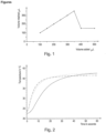
- Fig. 1 is a graph demonstrating the functionality provided by a sub-reservoir defined by a strip supporting structure comprising a weir structure within the fluid reservoir of a strip holder.
- the x-axis shows the volume in ⁇ L introduced into the strip holder
- the y-axis shows the volume in ⁇ L that was retained in the sub-reservoir.
- the nominal geometrical volume defined by the sub-reservoir defined by a strip supporting structure comprising a weir structure was 250 ⁇ L. Due to water surface tension also volumes higher than the nominal geometrical volume of the first sub-reservoir were retained. However, these volumes did not result in strip drowning.
- Fig. 2 is a graph showing the heat transfer behavior of different example strip holder back sides.
- the x-axis shows the time in seconds, and the y-axis shows the measured temperature in °C.
- the dotted line represents the data recorded when using a strip holder with a back side A (50 ⁇ m polyolefin film with 50 ⁇ m inert encapsulated silicone adhesive).
- the dashed line represents the data recorded when using a strip holder with a back side B (38 ⁇ m non-permeable soft aluminum foil).
- the solid line represents the data recorded when using the strip holder with a back side C (0.5 mm acrylonitrile butadiene styrene-like plastic foil).
- All tested back side materials have a specific heat transfer index of more than 0.08 s -1 and were thus found suitable to allow efficient heat transfer from an external heating/cooling source into the strip holder.
- independence from ambient temperature can be achieved and lateral flow assays can be performed at an operator-defined temperature and thus in a more reproducible and reliable manner.
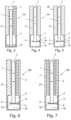
- strip receiving channels 2 or fluid receiving channels 3 have an open end located essentially at the top of the strip holder. In particular, these channels are provided in a way to allow insertion of a strip or of a fluid into a strip receiving channel 2 or a fluid receiving channel 3, respectively, from the top end of the strip holder 100.
- Fig. 3 is a frontal cross-section view of a strip holder 100, comprising a channel, which serves as a strip receiving channel 2 and a second channel which serves as a fluid receiving channel 3, wherein the strip receiving channel 2 and the fluid receiving channel 3 are provided in a parallel orientation to one another.
- the cross-section shown in Fig. 3 further shows a lateral flow test strip 1 contacting a fluid 101, contained in a fluid reservoir 4.
- Channels and fluid reservoir are formed by wall structures 21 which connect the strip holder front side 9 with the back side 11.
- a strip holder can be contacted with a heating/cooling element to achieve efficient temperature transfer from the heating/cooling element via the back side 11 to the content of the strip holder 100, thus allowing a detection of analytes at an operator-controlled temperature.
- Fig. 4 is a frontal cross-section view of another embodiment of a strip holder 100, comprising a strip receiving channel 2, which serves also as fluid receiving channel, and in addition comprising a strip supporting structure 5 with a weir structure 6.
- This strip supporting structure 5 with a weir structure 6 can e.g. be attached to one of wall structures 21 of the fluid reservoir 4.
- the sub-reservoir 17 formed by this strip supporting structure 5 with a weir structure 6 partly separates the fluid reservoir 4 and defines a first sub-reservoir 17 within the fluid reservoir 4. Underneath the first sub-reservoir 17, is a second sub-reservoir 18.
- a strip holder 100 comprising a strip supporting structure 5 with a weir structure 6 can be used to avoid strip drowning by accidental addition of excess liquid.
- Added liquid will first fill up the first sub-reservoir 17 formed by the strip supporting structure 5 with at least one weir structure 6, and only when the maximum volume of this first sub-reservoir 17 is reached, excess liquid will flow over the weir structure into the second sub-reservoir 18, thus avoiding drowning of the lateral flow test strip 1 standing in the first sub-reservoir 17.
- the strip receiving channel 2 and the fluid receiving channel are realized by the same channel.
- the liquid to be analyzed is introduced into the strip holder 100 via the same channel 2 which is used to introduce the lateral flow test strip 1 into the strip holder 100.
- the strip receiving channel 2 and the fluid receiving channel 3 are separate channels. By separating the strip receiving channel 2 and the fluid receiving channel 3, the risk of premature wetting of the lateral flow test strip 1 can be avoided and assay handling can be performed more conveniently.
- FIGs. 9-10 an additional ventilation channel 7 is shown.
- the ventilation channel 7 partially surrounds the fluid reservoir 4.
- the presence of a ventilation channel allows avoidance of back pressure build-up in the strip holder 100.
- the risk of blocking the ventilation channel 7 by spilling of liquid into the ventilation channel 7 can be reduced.
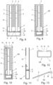
- Fig. 8 is a frontal cross-section view of an embodiment of a strip holder 100 according to the present invention, wherein two lateral flow assay strips 1 can be used in the same strip holder 100. It is apparent to a person skilled in the art, that also strip holders can be provided, which allow processing of three or even more lateral flow assay strips. Also such strip holders are encompassed by the present invention.
- the view of Fig. 8 shows a strip holder comprising two strip receiving channels 2, two fluid receiving channels 3, two separate strip supporting structures 5 with weir structures 6. Instead of having two separate strip supporting structures 5 with weir structures 6, it would also be possible to provide a single strip supporting structure with at least one weir structure, which supports two or more lateral flow test strips.
- Fig. 10 is a frontal cross-section view showing a strip holder 100 comprising a funnel 8.
- introduction of a fluid into the strip holder 100 can be achieved most conveniently via this funnel 8.
- a funnel 8 with at least two differently beveled inner surfaces 14, 15 and 16
- Fig. 11 is a lateral cross-section view of a strip holder 100 with a front side 9 having an inspection window 10 and a back side 11, comprising a wedge-shaped element 12, a strip supporting structure 5 and a weir structure 6.
- the inspection window 10 is indicated as dashed line.
- the wedge-shaped element 12 inhibits insertion of a typical lateral flow test strip into the strip holder 100 in the wrong orientation on the one hand, and applies pressure on a correctly inserted lateral flow test strip to push the strip against the back side 11 of the strip holder 100.
- a temperature-isolating air gap between the test strip and the back side 11 is minimized, thus achieving ideal temperature transfer from an external heating/cooling element via the back side 11 of the strip holder 100 onto the test strip.
- Fig. 12 is a horizontal cross-section view of a strip holder 100 with a back side 11 and a front side 9 having an inspection window 10, wherein the lateral walls 13 of the inspection window 10 are beveled.
- the back side 11 can be made of the same material as other components of the strip holder, such as the front side 9. It is however apparent that the back side 11 may also be made of a different material than one or more of the other components or structural elements of the strip holder, as disclosed herein.
- Example 1 Avoidance of strip drowning and strip holder flooding
- a strip holder was tested consisting of a housing with a front side comprising an inspection window and a back side, wherein the housing comprised one strip receiving channel and one separate fluid receiving channel, one fluid reservoir and one ventilation channel, wherein the strip receiving channel and the fluid receiving channel were in fluid connection with the fluid reservoir, and wherein the fluid reservoir was partly separated into a first and a second sub-reservoir by a strip supporting structure comprising a weir structure below the strip receiving channel and the fluid receiving channel ( Fig. 7 ).
- the strip supporting structure was provided to form a first sub-reservoir, defining a nominal geometrical volume of 250 ⁇ L, defined by the strip supporting structure orthogonal to the strip receiving channel and the fluid receiving channel, by the back side and the front side of the housing, the lateral wall of the housing and the weir structure. Excess liquid should overflow via the weir structure into the second sub-reservoir below the strip supporting structure, thus avoiding drowning of a strip standing in the strip receiving channel on the strip supporting structure.
- an aqueous solution containing a known concentration of 0.50 ppm of fumonisin B1 was measured in standard LFD assays at three different temperatures: at optimal temperature, 5 °C below the optimal temperature, and 5 °C above the optimal temperature.
- the fumonisin B1 concentration determined at optimal temperature was 0.49 ppm
- the concentration determined 5 °C below the optimal temperature was 0.64 ppm
- the concentration determined 5 °C above the optimal temperature was 0.37 ppm.
- a common laboratory hotplate e.g. RCT basic, IKA
- the strip holder to be measured was fitted with a temperature probe (e.g. Traceable Digital Thermometer, VWR) directly in contact with the inside of the back side at approximately the same height, as the test area of a test strip would sit.
- the strip holder was then fixed flat onto the hot plate with tape to ensure a close contact, while probe temperature, ambient temperature and incubation time were recorded. Before each new experiment, the temperature probe was allowed to cool down to room temperature, i.e. a temperature between 18 °C and 25 °C.
- metal foils as well as plastic foils were tested as strip holder back sides at different thicknesses.
- Aluminum foils were described to have a thickness of either 9 ⁇ m, 40 ⁇ m, 125 ⁇ m, 0.5 mm, 1 mm or 1.5 mm.
- Copper as well as silver foils were described to have a thickness of either 1 ⁇ m, 50 ⁇ m or 1 mm.
- Zinc foils were described to have a thickness of either 35 ⁇ m or 0.5 mm.
- Foils made of polyethylene, polyvinylchloride, polypropylene, polyester, polycarbonate, polystyrene or acrylonitrile butadiene styrene (ABS) were described to have a thickness of either 8 ⁇ m, 40 ⁇ m, 0.1 mm, 0.5 mm or 1 mm.
- the nominal thermal conductivity parameter of aluminum is in the range of approximately 200 W/(m*K), of copper approximately 275 W/(m*K), of silver approximately 430 W/(m*K) and of zinc approximately 110 W/(m*K).
- a back side A was "ThermaSeal RTS TM Sealing Film” purchased from Sigma-Aldrich bottles GmbH. This polyethylene-based film is described as 50 ⁇ m thick polyolefin with 50 ⁇ m inert encapsulated silicone adhesive.
- a back side B was "AlumaSeal ® II Seal” purchased from Sigma-Aldrich bottles GmbH.
- This film is described as a 38 ⁇ m non-permeable soft aluminum foil.
- a back side C was a 0.5 mm acrylonitrile butadiene styrene (ABS)-like polymer foil.
- ABS acrylonitrile butadiene styrene
- the time in seconds required to achieve a temperature transfer of 10 °C from 25 °C to 35 °C from the outside of the back side of a strip holder housing to the inside of the back side of the strip holder housing was measured.
- the time was 6.9 s.
- the time was 5.7 s.
- the time was 12 s.
- the specific heat transfer indices were determined by calculating the reciprocal of the times measured.
- the specific heat transfer index for a strip holder with back side A was determined to be 0.145 s -1 .
- the specific heat transfer index for a strip holder with back side B was determined to be 0.175 s -1 .
- the specific heat transfer index for a strip holder with back side C was determined to be 0.083 s -1 .
- the time required to achieve a temperature transfer of 10 °C from 25 °C to 35 °C from the outside of the back side of a strip holder housing to the inside of the back side of the strip holder housing did not exceed 60 s with any of the tested back sides.
- the specific heat transfer index of these strip holder back sides was at least 0.0167 s -1 .
Landscapes
- Health & Medical Sciences (AREA)
- Life Sciences & Earth Sciences (AREA)
- Chemical & Material Sciences (AREA)
- Immunology (AREA)
- Engineering & Computer Science (AREA)
- Biomedical Technology (AREA)
- Hematology (AREA)
- Analytical Chemistry (AREA)
- General Health & Medical Sciences (AREA)
- Physics & Mathematics (AREA)
- General Physics & Mathematics (AREA)
- Molecular Biology (AREA)
- Pathology (AREA)
- Biochemistry (AREA)
- Urology & Nephrology (AREA)
- Medicinal Chemistry (AREA)
- Food Science & Technology (AREA)
- Biotechnology (AREA)
- Microbiology (AREA)
- Cell Biology (AREA)
- Clinical Laboratory Science (AREA)
- Chemical Kinetics & Catalysis (AREA)
- Optics & Photonics (AREA)
- Biophysics (AREA)
- Automatic Analysis And Handling Materials Therefor (AREA)
- Vehicle Step Arrangements And Article Storage (AREA)
- Electrical Discharge Machining, Electrochemical Machining, And Combined Machining (AREA)
- Coating With Molten Metal (AREA)
Applications Claiming Priority (2)
| Application Number | Priority Date | Filing Date | Title |
|---|---|---|---|
| EP19213543 | 2019-12-04 | ||
| PCT/EP2020/068564 WO2021110290A1 (en) | 2019-12-04 | 2020-07-01 | Strip holder |
Publications (2)
| Publication Number | Publication Date |
|---|---|
| EP4070101A1 EP4070101A1 (en) | 2022-10-12 |
| EP4070101B1 true EP4070101B1 (en) | 2024-12-04 |
Family
ID=68771513
Family Applications (1)
| Application Number | Title | Priority Date | Filing Date |
|---|---|---|---|
| EP20734965.5A Active EP4070101B1 (en) | 2019-12-04 | 2020-07-01 | Strip holder |
Country Status (8)
| Country | Link |
|---|---|
| US (1) | US20230013282A1 (pl) |
| EP (1) | EP4070101B1 (pl) |
| CN (1) | CN112903744B (pl) |
| BR (1) | BR112022010662A2 (pl) |
| ES (1) | ES3014255T3 (pl) |
| MX (1) | MX2022006730A (pl) |
| PL (1) | PL4070101T3 (pl) |
| WO (1) | WO2021110290A1 (pl) |
Families Citing this family (1)
| Publication number | Priority date | Publication date | Assignee | Title |
|---|---|---|---|---|
| WO2025078295A1 (en) * | 2023-10-10 | 2025-04-17 | F. Hoffmann-La Roche Ag | An iva test unit, a test set comprising the iva test unit and a method of producing the same |
Family Cites Families (16)
| Publication number | Priority date | Publication date | Assignee | Title |
|---|---|---|---|---|
| US5242606A (en) * | 1990-06-04 | 1993-09-07 | Abaxis, Incorporated | Sample metering port for analytical rotor having overflow chamber |
| WO2001029558A1 (en) * | 1999-10-21 | 2001-04-26 | Oy Medix Biochemica Ab | A test strip provided device with a lid-provided pretreatment portion |
| US6338969B1 (en) | 1999-11-15 | 2002-01-15 | Bayer Corporation | Assay test system for regulating temperature |
| EP1393072A1 (en) | 2001-05-17 | 2004-03-03 | Bayer Healthcare LLC | Assay test system for regulating temperature |
| US6740293B1 (en) * | 2001-07-17 | 2004-05-25 | Biotech Atlantic, Inc. | Housing for test strip device and test strip therefor |
| US7285425B2 (en) | 2002-05-14 | 2007-10-23 | Siemens Medical Solutions Diagnostics | Assay test system for regulating temperature |
| US20050163658A1 (en) * | 2004-01-28 | 2005-07-28 | Naishu Wang | Interrupted, vertical flow testing device |
| EP1686378B1 (en) * | 2005-01-28 | 2010-11-17 | DNT Scientific Research, LLC | Fluid flow diffuser for immunological testing devices and method |
| AT505372A3 (de) * | 2007-05-21 | 2011-05-15 | Erber Ag | Verfahren zur quantitativen bestimmung von analyten mit einem testelement sowie testsystem und verwendung desselben |
| US8475731B2 (en) | 2007-09-21 | 2013-07-02 | Charm Sciences, Inc. | Lateral flow assay reader with transparent barrier in insert |
| US9008373B2 (en) | 2010-05-06 | 2015-04-14 | Charm Sciences, Inc. | Device, system and method for transit testing of samples |
| CN201974305U (zh) * | 2011-01-15 | 2011-09-14 | 艾博生物医药(杭州)有限公司 | 一种样本收集检测装置 |
| DE102012011411B3 (de) * | 2012-06-08 | 2013-11-28 | Dräger Safety AG & Co. KGaA | Testsystem zum Portionieren, Mischen und Verteilen von biologischen Probenflüssigkeiten |
| CN203720181U (zh) * | 2014-03-13 | 2014-07-16 | 郑晖 | 一种快速检验试剂盒 |
| WO2018125271A1 (en) * | 2016-12-28 | 2018-07-05 | Neogen Corporation | Fluid retainer cartridge assembly and method for utilizing the same |
| TWI646330B (zh) * | 2017-10-20 | 2019-01-01 | 威剛科技股份有限公司 | 液體檢測匣 |
-
2020
- 2020-07-01 MX MX2022006730A patent/MX2022006730A/es unknown
- 2020-07-01 EP EP20734965.5A patent/EP4070101B1/en active Active
- 2020-07-01 PL PL20734965.5T patent/PL4070101T3/pl unknown
- 2020-07-01 US US17/782,280 patent/US20230013282A1/en active Pending
- 2020-07-01 BR BR112022010662A patent/BR112022010662A2/pt unknown
- 2020-07-01 ES ES20734965T patent/ES3014255T3/es active Active
- 2020-07-01 WO PCT/EP2020/068564 patent/WO2021110290A1/en not_active Ceased
- 2020-12-04 CN CN202011413666.1A patent/CN112903744B/zh active Active
Also Published As
| Publication number | Publication date |
|---|---|
| ES3014255T3 (en) | 2025-04-21 |
| US20230013282A1 (en) | 2023-01-19 |
| PL4070101T3 (pl) | 2025-06-23 |
| CN112903744B (zh) | 2025-07-25 |
| CN112903744A (zh) | 2021-06-04 |
| MX2022006730A (es) | 2022-06-09 |
| EP4070101A1 (en) | 2022-10-12 |
| BR112022010662A2 (pt) | 2022-08-16 |
| WO2021110290A1 (en) | 2021-06-10 |
Similar Documents
| Publication | Publication Date | Title |
|---|---|---|
| EP1102066B1 (en) | Assay test system with temperature control means | |
| US4814279A (en) | Incubator for chemical-analytical slide | |
| CN1308681C (zh) | 用于流体注射的载片盒 | |
| EP0662345B1 (en) | Apparatus for heating a fluid-carrying compartment of a reaction cuvette | |
| US9393563B2 (en) | Strip for lateral flow assay, comprising subpad, and cartridge for lateral flow assay used for the same | |
| KR101149357B1 (ko) | 반사식 흡광도 측정 장치 및 이를 포함하는 반사식 흡광도 및 측방유동 분석 일체형 장치 | |
| US7989214B2 (en) | Self-sealing microreactor and method for carrying out a reaction | |
| EP2994761B1 (en) | Imaging cartridge, pipette, and method of use for direct sputum smear microscopy | |
| EP0064691B1 (en) | Apparatus comprising a magazine retaining multiple flexible test strips and means for removing a single test strip, and method of dispensing such strips using this apparatus | |
| AU2022203626B2 (en) | Sampling array devices and system for spectral analysis | |
| EP3726214A1 (en) | Immunochromatographic test device | |
| US7285425B2 (en) | Assay test system for regulating temperature | |
| US5569607A (en) | Slide for the microscopic evaluation of liquid specimens | |
| US20190168209A1 (en) | Test device | |
| EP4070101B1 (en) | Strip holder | |
| WO2017058788A1 (en) | Systems and methods for a lateral flow test strip holder | |
| US4727032A (en) | Process for the thermostatic control of a sample fluid to be analyzed, apparatus for performing the process | |
| JP4662952B2 (ja) | 流体の流れを導くためのベントを有する流体試験センサ | |
| JP2008292197A (ja) | テストストリップ用デバイス | |
| US11391676B2 (en) | Test element analysis system for the analytical examination of a sample | |
| CA2398348A1 (en) | Devices for analyte concentration determination and methods of using the same | |
| EP0121863B1 (en) | Automated reagent blotter | |
| WO2009050435A1 (en) | Testing apparatus and method with dosing mechanis | |
| JP7217133B2 (ja) | 検査用デバイス | |
| JP2903275B2 (ja) | 乾式分析フィルム片の押え装置 |
Legal Events
| Date | Code | Title | Description |
|---|---|---|---|
| STAA | Information on the status of an ep patent application or granted ep patent |
Free format text: STATUS: UNKNOWN |
|
| STAA | Information on the status of an ep patent application or granted ep patent |
Free format text: STATUS: THE INTERNATIONAL PUBLICATION HAS BEEN MADE |
|
| PUAI | Public reference made under article 153(3) epc to a published international application that has entered the european phase |
Free format text: ORIGINAL CODE: 0009012 |
|
| STAA | Information on the status of an ep patent application or granted ep patent |
Free format text: STATUS: REQUEST FOR EXAMINATION WAS MADE |
|
| 17P | Request for examination filed |
Effective date: 20220519 |
|
| AK | Designated contracting states |
Kind code of ref document: A1 Designated state(s): AL AT BE BG CH CY CZ DE DK EE ES FI FR GB GR HR HU IE IS IT LI LT LU LV MC MK MT NL NO PL PT RO RS SE SI SK SM TR |
|
| DAV | Request for validation of the european patent (deleted) | ||
| DAX | Request for extension of the european patent (deleted) | ||
| STAA | Information on the status of an ep patent application or granted ep patent |
Free format text: STATUS: EXAMINATION IS IN PROGRESS |
|
| 17Q | First examination report despatched |
Effective date: 20230818 |
|
| GRAP | Despatch of communication of intention to grant a patent |
Free format text: ORIGINAL CODE: EPIDOSNIGR1 |
|
| STAA | Information on the status of an ep patent application or granted ep patent |
Free format text: STATUS: GRANT OF PATENT IS INTENDED |
|
| INTG | Intention to grant announced |
Effective date: 20240625 |
|
| P01 | Opt-out of the competence of the unified patent court (upc) registered |
Free format text: CASE NUMBER: APP_49364/2024 Effective date: 20240830 |
|
| GRAS | Grant fee paid |
Free format text: ORIGINAL CODE: EPIDOSNIGR3 |
|
| GRAA | (expected) grant |
Free format text: ORIGINAL CODE: 0009210 |
|
| STAA | Information on the status of an ep patent application or granted ep patent |
Free format text: STATUS: THE PATENT HAS BEEN GRANTED |
|
| RAP1 | Party data changed (applicant data changed or rights of an application transferred) |
Owner name: DSM IP ASSETS B.V. |
|
| AK | Designated contracting states |
Kind code of ref document: B1 Designated state(s): AL AT BE BG CH CY CZ DE DK EE ES FI FR GB GR HR HU IE IS IT LI LT LU LV MC MK MT NL NO PL PT RO RS SE SI SK SM TR |
|
| REG | Reference to a national code |
Ref country code: CH Ref legal event code: EP |
|
| REG | Reference to a national code |
Ref country code: DE Ref legal event code: R096 Ref document number: 602020042481 Country of ref document: DE |
|
| REG | Reference to a national code |
Ref country code: IE Ref legal event code: FG4D |
|
| REG | Reference to a national code |
Ref country code: NL Ref legal event code: FP |
|
| REG | Reference to a national code |
Ref country code: LT Ref legal event code: MG9D |
|
| PG25 | Lapsed in a contracting state [announced via postgrant information from national office to epo] |
Ref country code: HR Free format text: LAPSE BECAUSE OF FAILURE TO SUBMIT A TRANSLATION OF THE DESCRIPTION OR TO PAY THE FEE WITHIN THE PRESCRIBED TIME-LIMIT Effective date: 20241204 |
|
| PG25 | Lapsed in a contracting state [announced via postgrant information from national office to epo] |
Ref country code: FI Free format text: LAPSE BECAUSE OF FAILURE TO SUBMIT A TRANSLATION OF THE DESCRIPTION OR TO PAY THE FEE WITHIN THE PRESCRIBED TIME-LIMIT Effective date: 20241204 |
|
| PG25 | Lapsed in a contracting state [announced via postgrant information from national office to epo] |
Ref country code: BG Free format text: LAPSE BECAUSE OF FAILURE TO SUBMIT A TRANSLATION OF THE DESCRIPTION OR TO PAY THE FEE WITHIN THE PRESCRIBED TIME-LIMIT Effective date: 20241204 |
|
| REG | Reference to a national code |
Ref country code: ES Ref legal event code: FG2A Ref document number: 3014255 Country of ref document: ES Kind code of ref document: T3 Effective date: 20250421 |
|
| PG25 | Lapsed in a contracting state [announced via postgrant information from national office to epo] |
Ref country code: NO Free format text: LAPSE BECAUSE OF FAILURE TO SUBMIT A TRANSLATION OF THE DESCRIPTION OR TO PAY THE FEE WITHIN THE PRESCRIBED TIME-LIMIT Effective date: 20250304 |
|
| PG25 | Lapsed in a contracting state [announced via postgrant information from national office to epo] |
Ref country code: LV Free format text: LAPSE BECAUSE OF FAILURE TO SUBMIT A TRANSLATION OF THE DESCRIPTION OR TO PAY THE FEE WITHIN THE PRESCRIBED TIME-LIMIT Effective date: 20241204 Ref country code: GR Free format text: LAPSE BECAUSE OF FAILURE TO SUBMIT A TRANSLATION OF THE DESCRIPTION OR TO PAY THE FEE WITHIN THE PRESCRIBED TIME-LIMIT Effective date: 20250305 |
|
| PG25 | Lapsed in a contracting state [announced via postgrant information from national office to epo] |
Ref country code: RS Free format text: LAPSE BECAUSE OF FAILURE TO SUBMIT A TRANSLATION OF THE DESCRIPTION OR TO PAY THE FEE WITHIN THE PRESCRIBED TIME-LIMIT Effective date: 20250304 |
|
| PG25 | Lapsed in a contracting state [announced via postgrant information from national office to epo] |
Ref country code: SM Free format text: LAPSE BECAUSE OF FAILURE TO SUBMIT A TRANSLATION OF THE DESCRIPTION OR TO PAY THE FEE WITHIN THE PRESCRIBED TIME-LIMIT Effective date: 20241204 |
|
| PGFP | Annual fee paid to national office [announced via postgrant information from national office to epo] |
Ref country code: PL Payment date: 20250627 Year of fee payment: 6 |
|
| PGFP | Annual fee paid to national office [announced via postgrant information from national office to epo] |
Ref country code: GB Payment date: 20250612 Year of fee payment: 6 |
|
| PG25 | Lapsed in a contracting state [announced via postgrant information from national office to epo] |
Ref country code: IS Free format text: LAPSE BECAUSE OF FAILURE TO SUBMIT A TRANSLATION OF THE DESCRIPTION OR TO PAY THE FEE WITHIN THE PRESCRIBED TIME-LIMIT Effective date: 20250404 |
|
| PGFP | Annual fee paid to national office [announced via postgrant information from national office to epo] |
Ref country code: NL Payment date: 20250613 Year of fee payment: 6 |
|
| PG25 | Lapsed in a contracting state [announced via postgrant information from national office to epo] |
Ref country code: PT Free format text: LAPSE BECAUSE OF FAILURE TO SUBMIT A TRANSLATION OF THE DESCRIPTION OR TO PAY THE FEE WITHIN THE PRESCRIBED TIME-LIMIT Effective date: 20250404 |
|
| PG25 | Lapsed in a contracting state [announced via postgrant information from national office to epo] |
Ref country code: EE Free format text: LAPSE BECAUSE OF FAILURE TO SUBMIT A TRANSLATION OF THE DESCRIPTION OR TO PAY THE FEE WITHIN THE PRESCRIBED TIME-LIMIT Effective date: 20241204 |
|
| PGFP | Annual fee paid to national office [announced via postgrant information from national office to epo] |
Ref country code: FR Payment date: 20250610 Year of fee payment: 6 |
|
| PG25 | Lapsed in a contracting state [announced via postgrant information from national office to epo] |
Ref country code: RO Free format text: LAPSE BECAUSE OF FAILURE TO SUBMIT A TRANSLATION OF THE DESCRIPTION OR TO PAY THE FEE WITHIN THE PRESCRIBED TIME-LIMIT Effective date: 20241204 |
|
| PG25 | Lapsed in a contracting state [announced via postgrant information from national office to epo] |
Ref country code: SK Free format text: LAPSE BECAUSE OF FAILURE TO SUBMIT A TRANSLATION OF THE DESCRIPTION OR TO PAY THE FEE WITHIN THE PRESCRIBED TIME-LIMIT Effective date: 20241204 |
|
| PG25 | Lapsed in a contracting state [announced via postgrant information from national office to epo] |
Ref country code: CZ Free format text: LAPSE BECAUSE OF FAILURE TO SUBMIT A TRANSLATION OF THE DESCRIPTION OR TO PAY THE FEE WITHIN THE PRESCRIBED TIME-LIMIT Effective date: 20241204 |
|
| REG | Reference to a national code |
Ref country code: DE Ref legal event code: R097 Ref document number: 602020042481 Country of ref document: DE |
|
| PG25 | Lapsed in a contracting state [announced via postgrant information from national office to epo] |
Ref country code: SE Free format text: LAPSE BECAUSE OF FAILURE TO SUBMIT A TRANSLATION OF THE DESCRIPTION OR TO PAY THE FEE WITHIN THE PRESCRIBED TIME-LIMIT Effective date: 20241204 |
|
| PGFP | Annual fee paid to national office [announced via postgrant information from national office to epo] |
Ref country code: ES Payment date: 20250807 Year of fee payment: 6 |
|
| PG25 | Lapsed in a contracting state [announced via postgrant information from national office to epo] |
Ref country code: DK Free format text: LAPSE BECAUSE OF FAILURE TO SUBMIT A TRANSLATION OF THE DESCRIPTION OR TO PAY THE FEE WITHIN THE PRESCRIBED TIME-LIMIT Effective date: 20241204 |
|
| PGFP | Annual fee paid to national office [announced via postgrant information from national office to epo] |
Ref country code: DE Payment date: 20250618 Year of fee payment: 6 |
|
| PLBE | No opposition filed within time limit |
Free format text: ORIGINAL CODE: 0009261 |
|
| STAA | Information on the status of an ep patent application or granted ep patent |
Free format text: STATUS: NO OPPOSITION FILED WITHIN TIME LIMIT |
|
| PGFP | Annual fee paid to national office [announced via postgrant information from national office to epo] |
Ref country code: IT Payment date: 20250623 Year of fee payment: 6 |
|
| PGFP | Annual fee paid to national office [announced via postgrant information from national office to epo] |
Ref country code: AT Payment date: 20250625 Year of fee payment: 6 |
|
| 26N | No opposition filed |
Effective date: 20250905 |