EP4070064B1 - System and method for grounded high voltage leak detection - Google Patents
System and method for grounded high voltage leak detection Download PDFInfo
- Publication number
- EP4070064B1 EP4070064B1 EP20920142.5A EP20920142A EP4070064B1 EP 4070064 B1 EP4070064 B1 EP 4070064B1 EP 20920142 A EP20920142 A EP 20920142A EP 4070064 B1 EP4070064 B1 EP 4070064B1
- Authority
- EP
- European Patent Office
- Prior art keywords
- package
- inspection
- grounding
- hvld
- grounding element
- Prior art date
- Legal status (The legal status is an assumption and is not a legal conclusion. Google has not performed a legal analysis and makes no representation as to the accuracy of the status listed.)
- Active
Links
Images

Classifications
-
- G—PHYSICS
- G01—MEASURING; TESTING
- G01M—TESTING STATIC OR DYNAMIC BALANCE OF MACHINES OR STRUCTURES; TESTING OF STRUCTURES OR APPARATUS, NOT OTHERWISE PROVIDED FOR
- G01M3/00—Investigating fluid-tightness of structures
- G01M3/40—Investigating fluid-tightness of structures by using electric means, e.g. by observing electric discharges
-
- G—PHYSICS
- G01—MEASURING; TESTING
- G01M—TESTING STATIC OR DYNAMIC BALANCE OF MACHINES OR STRUCTURES; TESTING OF STRUCTURES OR APPARATUS, NOT OTHERWISE PROVIDED FOR
- G01M3/00—Investigating fluid-tightness of structures
- G01M3/02—Investigating fluid-tightness of structures by using fluid or vacuum
- G01M3/04—Investigating fluid-tightness of structures by using fluid or vacuum by detecting the presence of fluid at the leakage point
- G01M3/16—Investigating fluid-tightness of structures by using fluid or vacuum by detecting the presence of fluid at the leakage point using electric detection means
- G01M3/18—Investigating fluid-tightness of structures by using fluid or vacuum by detecting the presence of fluid at the leakage point using electric detection means for pipes, cables or tubes; for pipe joints or seals; for valves; for welds; for containers, e.g. radiators
- G01M3/186—Investigating fluid-tightness of structures by using fluid or vacuum by detecting the presence of fluid at the leakage point using electric detection means for pipes, cables or tubes; for pipe joints or seals; for valves; for welds; for containers, e.g. radiators for containers, e.g. radiators
-
- G—PHYSICS
- G01—MEASURING; TESTING
- G01M—TESTING STATIC OR DYNAMIC BALANCE OF MACHINES OR STRUCTURES; TESTING OF STRUCTURES OR APPARATUS, NOT OTHERWISE PROVIDED FOR
- G01M3/00—Investigating fluid-tightness of structures
- G01M3/02—Investigating fluid-tightness of structures by using fluid or vacuum
- G01M3/04—Investigating fluid-tightness of structures by using fluid or vacuum by detecting the presence of fluid at the leakage point
- G01M3/16—Investigating fluid-tightness of structures by using fluid or vacuum by detecting the presence of fluid at the leakage point using electric detection means
-
- G—PHYSICS
- G01—MEASURING; TESTING
- G01N—INVESTIGATING OR ANALYSING MATERIALS BY DETERMINING THEIR CHEMICAL OR PHYSICAL PROPERTIES
- G01N33/00—Investigating or analysing materials by specific methods not covered by groups G01N1/00 - G01N31/00
- G01N33/0078—Testing material properties on manufactured objects
- G01N33/0081—Containers; Packages; Bottles
-
- G—PHYSICS
- G01—MEASURING; TESTING
- G01R—MEASURING ELECTRIC VARIABLES; MEASURING MAGNETIC VARIABLES
- G01R31/00—Arrangements for testing electric properties; Arrangements for locating electric faults; Arrangements for electrical testing characterised by what is being tested not provided for elsewhere
- G01R31/12—Testing dielectric strength or breakdown voltage ; Testing or monitoring effectiveness or level of insulation, e.g. of a cable or of an apparatus, for example using partial discharge measurements; Electrostatic testing
- G01R31/14—Circuits therefor, e.g. for generating test voltages, sensing circuits
-
- G—PHYSICS
- G01—MEASURING; TESTING
- G01R—MEASURING ELECTRIC VARIABLES; MEASURING MAGNETIC VARIABLES
- G01R31/00—Arrangements for testing electric properties; Arrangements for locating electric faults; Arrangements for electrical testing characterised by what is being tested not provided for elsewhere
- G01R31/12—Testing dielectric strength or breakdown voltage ; Testing or monitoring effectiveness or level of insulation, e.g. of a cable or of an apparatus, for example using partial discharge measurements; Electrostatic testing
- G01R31/16—Construction of testing vessels; Electrodes therefor
Definitions
- the present disclosure relates to systems and methods for high voltage leak detection.
- High voltage leak detection is one of the emerging technologies for inspecting leakage.
- HVLD operates by applying a high voltage potential to an electrically conductive substance inside non-conductive package or container. Defects are identified when the electrical discharges are detected between the substance inside the package and HVLD electrodes.
- a HVLD testing process may include of a set of electrodes scanning a sealed package containing a liquid. The presence of a current flow or voltage between the set of electrodes indicates a breach of the package closure, which may be attributed by the presence of a crack, a leak, a pin hole, or a seal imperfection.
- WO 2004/051255 A1 discloses a HVLD device for inspecting packages comprising a high voltage inspection electrode, a detection electrode and a ground electrode in contact with the package.
- WO 2019/157036 A1 discloses a HVLD device comprising a plurality of electrodes arranged at a distance from a medication container to be inspected.
- the present disclosure is related to systems and methods for high voltage leakage detection (HVLD).
- HVLD operates by applying a high voltage potential to an electrically conductive substance inside non-conductive package or container.
- the presence of a current flow or voltage between the inspecting electrodes can indicate a breach of the package closure, which may be attributed to the presence of a crack, a leak, a pin hole, or a seal imperfection.
- the results may become less consistent as the inspection proceeds and/or when subsequent inspections are performed on the same package.
- the inconsistent results may lead to inaccurate and/or unreliable leakage detection.
- the results from the first-time inspection are acceptable but the results from the subsequent inspections (e.g., the second-time inspection, third-time inspection, and so forth) may be inconsistent.
- the HVLD test results are often masked by signal noises with a lower signal-to-noise ratio (SNR) in the subsequent inspections.
- SNR is a measure used in data analysis that compares the level of the desired signal to the level of background noise, and SNR is defined as the ratio of the signal power to the noise power (e.g., a ratio higher than 1: 1 indicates more signal than noise).
- the systems and methods described herein may include a system grounding the package before, during, and/or after the HVLD inspection. As the package is grounded to remove the static charge accumulated during the HVLD inspection, signal noise is substantially removed or significantly reduced, leading to an enhanced SNR.
- the enhanced SNR may improve the reliability and/or accuracy of the HVLD inspection.
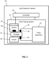
- FIG. 1 shows a diagram of an example leak detection system 10 configured to inspect a package 12 in accordance with an embodiment of the present disclosure.
- the leak detection system 10 includes a HVLD testing system 14, a grounding system 16, and a controller 18 operatively and communicatively coupled to the HVLD testing system 14 and the grounding system 16.
- the package 12 may have any suitable shapes and may be made of any suitable non-conductive material (e.g., polymer, plastic, glass, ceramic, composites, etc.) to contain a liquid within the package 12.
- the package 12 may be an IV bag, a syringe, a vial, etc.
- the HVLD testing system 14 includes a holder 20 configured to retain and/or rotate the package 12.
- the holder 20 may include one or more rollers or rotational rests (e.g., one or more rods) configured to receive and/or rotate the package 12.
- the HVLD testing system 14 may include a HVLD apparatus 22 configured to perform HVLD inspection.
- the HVLD apparatus 22 may be any suitable leak detection circuit or apparatus to perform HVLD inspection on the package 12.
- the HVLD apparatus 22 may be a testing system or apparatus manufactured by Packaging Technologies and Inspection , LLC.
- the HVLD apparatus 14 may include a scanner 24 (e.g., E-Scan TM, model 655) that includes an inspection electrode 26 and a detection electrode 28 to inspect the package 12.
- the inspection electrode 26 and the detection electrode 28 are configured to be positioned near and/or contact opposite sides of the package 12 and scan across the package 12 to inspect the package 12.
- the grounding system 16 may include a grounding element 30 that is configured to be positioned near and/or contact the surface (e.g., outer surface) of the package 12 to remove, significantly reduce, or conduct away electric charge accumulation (e.g., static charge) on the package 12.
- the grounding element 30 may be configured to scan the surface of the package 12.
- the grounding element 30 may be configured to move together with the inspection electrode 26 and/or the detection electrode 28 to scan the surface of the package 12.
- the grounding element 30 may have any suitable shapes (e.g., brush, probe, pin, roller, rotational rest, rod, etc.) and may be made of any suitable electrically conductive or semi-conductive material (e.g., metal, alloy, conductive or semi-conductive polymer, etc.).
- the controller 18 may be configured to operate and coordinate the operation of the grounding system 16 with the operation of the HVLD testing system 14.
- the controller 18 may include any suitable processer (e.g., microprocessor, MOSFET, IGBT, etc.) and memory.
- the controller 18 may include any suitable user interface and/or display to allow a user to program and/or provide inputs to control the operation of the HVLD testing system 14 and/or the operation of the grounding system 16.
- the controller 18 may receive instructions from a user or may be preprogrammed to inspect the package 12 following certain procedures or predetermined procedures.
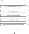
- FIG. 2 shows a method 40 for inspecting a package using the leak detection system 10.
- the steps discussed herein may be controlled and executed by the controller 18.
- the method 40 may include (step 42) providing a HVLD testing system configured to inspect a package using a scanner comprising an inspection electrode and a detection electrode.
- step 42 may include providing the HVLD testing system 14 or the HVLD apparatus 22.
- the method 100 may include (step 44) mounting a package (e.g., the package 12) and (step 46) providing a grounding system (e.g., the grounding system 16).
- Step 44 may include mounting the package 12 on the holder 22 of the HVLD testing system 14.
- Step 46 may include orienting and/or positioning the grounding system 16 (in particular the grounding element 30) in proximity of the package 12 and the HVLD apparatus 22 to allow inspection and grounding of the package 12.
- Step 46 may include configuring the controller 18 to control and coordinate the operation of the grounding system 16 with the operation of the HVLD testing system 14.
- the method 40 may include (step 48) grounding the package (e.g., the package 12) by positioning at least one grounding element near or contact the package to remove, significantly reduce, or conduct away electric charge accumulation on the package.
- the method 40 may include (step 50) performing HVLD inspection on the package.
- Step 50 may include using the HVLD testing system 14 to inspect the package 12 (e.g., using the HVLD apparatus 22 to scan the package 12).
- FIG. 3 show a schematic illustrating example processes of step 48.
- step 48 may include moving the grounding element 30 to a position between the inspection electrode 26 and the detection electrode 28.
- Step 48 may include moving the grounding element 30 to an effective distance 60 from the surface of the package 12 to ground the package 12.
- the effective distance 60 may be any suitable distances to effectively ground the package 12.
- the effective distance 60 may depend on many factors, e.g., the amount of charge accumulated, the material of the package 12, the material of the grounding element 30, the shape of the grounding element 30, the ambient environment (e.g., humidity), etc.
- the effective distance 60 may be about 0.1 millimeter (mm) to about 6 mm, about 0.1 mm to about 5 mm, or about 0.1 mm to about 3 mm.
- Step 48 may include moving the grounding element 30 to contact (e.g., the effective distance 60 is zero) the package 12.
- the grounding element 30 may be coupled to an actuator 62 which is configured to move the grounding element 30 in the x-direction, y-direction, z-direction, or any combination thereof.
- the actuator 62 may be any suitable types of actuator, including but are not limited to, a pneumatic actuator, a solenoid actuator, and a lead screw.
- the package 12 may be received by the holder 20 that includes one or more rollers or rotational rests 21 and 23 (e.g., rods, rotatable rods).
- the rollers or rotational rests 21 and 23 are configured to contact and/or rotate the package 12.
- the grounding element 30 may include the one or more rollers or rotational rests 21 and 23, and at least one of the rollers or rotational rests 21 and 23 are made of electrically conductive or semi-conductive material (e.g., metal, alloy, conductive or semi-conductive polymer, etc.).
- the one or more rollers or rotational rests 21 and 23 function as the grounding element 30 to ground the package 12 when the package 12 contacts or sits on the one or more rollers or rotational rests 21 and 23.
- at least one of the rollers or rotational rests 21 and 23 are made of titanium.
- Step 48 may be performed either before, during, or after performing a HVLD inspection.
- inspecting the package 12 using the HVLD testing system 14 and grounding the package 12 are performed at the same time (e.g., coordinated using the controller 18).
- step 48 includes moving the grounding element 30 along with the inspection electrode 26 and/or the detection electrode 28 such that the grounding element 30 is between the inspection electrode 26 and the detection electrode 28 during the HVLD inspection and the grounding element 30 does not interfere with the scanning of the inspection electrode 26 and the detection electrode 28.
- the grounding element 30 also movies in the y-direction at a suitable speed to maintain its position between the inspection electrode 26 and the detection electrode 28.
- the grounding element 30 is configured to maintain contact with the package 12 or maintain the effective distance 60 from the package 12 while moving along with the inspection electrode 26 and/or the detection electrode 28.
- step 50 is performed after step 48.
- step 50 is performed within a time period that the grounding effect is effective, e.g., step 50 is performed immediately after step 48, within a few minutes after step 48, or within a few seconds after step 48, etc.
- the grounding element 30 is positioned within the effective distance 60 from the surface of the package 12 or in direct contact with the package 12 to ground the package 12.
- the HVLD inspection proceeds after the package 12 has been grounded.
- step 48 is performed after step 50.
- the grounding element 30 is positioned within the effective distance 60 from the surface of the package 12 or in direct contact with the package 12 to ground the package 12 and to prepare the package for a subsequent HVLD inspection.
- the leak detection system 10 disclosed herein with the grounding system 16 is configured to remove the static charge accumulated on the inspection sample or package to reduce signal noise. As the signal noise is substantially removed or significantly reduced, the SNR can be enhanced, leading to improved reliability and/or accuracy of the HVLD inspection. In some embodiments, using the leak detection system 10 disclosed herein, the SNR may be increased by at least 10%, at least 20%, at least 30%, at least 40%, or at least 50%, compared to HVLD inspections obtained using a HVLD system without a grounding system. In some embodiments, using the leak detection system 10 disclosed herein, the SNR may be greater than about 4, greater than about 5, or greater than about 6.
- SNR is a measure used in data analysis that compares the level of the desired signal to the level of background noise, and SNR is defined as the ratio of the signal power to the noise power (e.g., a ratio higher than 1:1 indicates more signal than noise).
- the signal power is calculated as the difference between the minimum value of a positive control and the mean value of the negative control.
- a package of a 400 milliliter (mL) vial filled with a 100 microsiemens ( ⁇ S) solution was subjected to a HVLD inspection using the systems (e.g., the leak detection system 10) and methods (e.g., the method 40) disclosed herein with and without a grounding process.
- the grounding process was performed during the HVLD inspection.
- a ground brush e.g., the grounding element 30
- the ground brush was configured to remove surface charge from the vial and allow the signal corresponding to a defect to be clearly detected (e.g., distinguishable from the noise). It should be noted that although in the illustrated experiment, the grounding process was performed during the HVLD inspection, we may expect similar effects if the grounding process was performed before the HVLD inspection.
- Table 1 and FIG. 4 The experimental results from the ungrounded HVLD inspection are shown in Table 1 and FIG. 4 , and that of the grounded HVLD inspection are shown in Table 2 and FIG. 5 .
- Table. 1 Ungrounded 400 mL Vial Avg Std Min Max Avg+6*Std SNR Negative 5.64 0.20 5.07 6.05 6.85 4 Positive 9.86 0.38 8.01 10.00 - - Table 2.
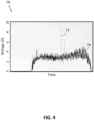
- FIG. 4 shows a plot 70 of the ungrounded HVLD inspection results.
- the x-axis indicates time and the y-axis indicates voltage in volt (V).
- Data series 72 and 74 correspond to a positive control and a negative control, respectively, and the corresponding average (Avg), standard deviation (Std), minimum (Min), maximum (Max), (Avg + 6*Std), and SNR values of the data series are summarized in Table 1.
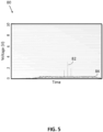
- FIG. 5 shows a plot 80 of the grounded HVLD inspection results. In the plot 80, the x-axis indicates time and the y-axis indicates voltage in volt (V).
- Data series 82 and 84 correspond to a positive control and a negative control, respectively, and the average (Avg), standard deviation (Std), minimum (Min), maximum (Max), (Avg + 6*Std), and SNR values of the data series are summarized in Table 1.
- the HVLD inspection data ( FIG. 5 ) obtained from the grounded vial indicate a clearer defect detection than that obtained from the ungrounded vial ( FIG. 4 ).
- the contrast or distinction between the positive control and negative control is more distinguishable in FIG. 5 than in FIG. 4 .
- the SNR of the data from the ungrounded HVLD inspection is only 4, whereas the SNR of the data from the grounded HVLD inspection is significantly increased by 50%, from 4 to 6.
Landscapes
- Physics & Mathematics (AREA)
- General Physics & Mathematics (AREA)
- Health & Medical Sciences (AREA)
- Life Sciences & Earth Sciences (AREA)
- Chemical & Material Sciences (AREA)
- Engineering & Computer Science (AREA)
- Food Science & Technology (AREA)
- Medicinal Chemistry (AREA)
- Analytical Chemistry (AREA)
- Biochemistry (AREA)
- General Health & Medical Sciences (AREA)
- Immunology (AREA)
- Pathology (AREA)
- Examining Or Testing Airtightness (AREA)
- Cable Accessories (AREA)
- Emergency Protection Circuit Devices (AREA)
- Investigating Or Analyzing Materials By The Use Of Electric Means (AREA)
Description
- The present disclosure relates to systems and methods for high voltage leak detection.
- High voltage leak detection (HVLD) is one of the emerging technologies for inspecting leakage. HVLD operates by applying a high voltage potential to an electrically conductive substance inside non-conductive package or container. Defects are identified when the electrical discharges are detected between the substance inside the package and HVLD electrodes. For example, a HVLD testing process may include of a set of electrodes scanning a sealed package containing a liquid. The presence of a current flow or voltage between the set of electrodes indicates a breach of the package closure, which may be attributed by the presence of a crack, a leak, a pin hole, or a seal imperfection.
- In the prior art,
WO 2004/051255 A1 discloses a HVLD device for inspecting packages comprising a high voltage inspection electrode, a detection electrode and a ground electrode in contact with the package.WO 2019/157036 A1 discloses a HVLD device comprising a plurality of electrodes arranged at a distance from a medication container to be inspected. - In one embodiment, it is provided a leak detection system according to claim 1.
- In another embodiment, it is provided a method of using the system of claim 1 for high voltage leak detection inspection, as defined in
claim 10. - The summary is provided merely for purposes of summarizing some example embodiments so as to provide a basic understanding of some aspects of the disclosure. Accordingly, it will be appreciated that the above-described examples should not be construed to narrow the scope of the disclosure in any way. Other examples, embodiments, aspects, and advantages will become apparent from the following detailed description taken in conjunction with the accompanying drawings.
-
-
FIG. 1 shows a diagram of a leak detection system including a HVLD testing system and a grounding system; -
FIG. 2 shows an example method of HVLD inspection using the leak detection system ofFIG. 1 ; -
FIG. 3 shows a front view of a partial schematic of the leak detection system ofFIG. 1 including the grounding system configured to ground a package before, during, and/or after inspecting the package; -
FIG. 4 shows an example HVLD inspection result from an ungrounded package inspected using the leak detection system ofFIG. 1 ; and -
FIG. 5 shows an example HVLD inspection result from a grounded package inspected using the leak detection system ofFIG. 1 . - The present disclosure is not limited in terms of the particular embodiments described in this application, which are intended as illustrations of various aspects only. Many modifications and variations can be made without departing from the scope of the invention, as will be apparent to those skilled in the art. Functionally equivalent methods within the scope of the disclosure, in addition to those enumerated herein, will be apparent to those skilled in the art from the following descriptions. Such modifications and variations are intended to fall within the scope of the appended claims. The terminology used herein is for the purpose of describing particular embodiments only, and is not intended to be limiting.
- The present disclosure is related to systems and methods for high voltage leakage detection (HVLD). In particular, the systems and methods disclosed herein seek to reduce signal noise and/or to improve the reliability of HVLD detection. HVLD operates by applying a high voltage potential to an electrically conductive substance inside non-conductive package or container. The presence of a current flow or voltage between the inspecting electrodes can indicate a breach of the package closure, which may be attributed to the presence of a crack, a leak, a pin hole, or a seal imperfection. However, it may be challenging to produce reliable and consistent results. In particular, when HVLD inspection is performed on a non-conductive package, the results may become less consistent as the inspection proceeds and/or when subsequent inspections are performed on the same package. The inconsistent results may lead to inaccurate and/or unreliable leakage detection. In an example, when HVLD inspection is performed on an intravenous (IV) bag, the results from the first-time inspection are acceptable but the results from the subsequent inspections (e.g., the second-time inspection, third-time inspection, and so forth) may be inconsistent. In particular, the HVLD test results are often masked by signal noises with a lower signal-to-noise ratio (SNR) in the subsequent inspections. SNR is a measure used in data analysis that compares the level of the desired signal to the level of background noise, and SNR is defined as the ratio of the signal power to the noise power (e.g., a ratio higher than 1: 1 indicates more signal than noise).
- The systems and methods described herein may include a system grounding the package before, during, and/or after the HVLD inspection. As the package is grounded to remove the static charge accumulated during the HVLD inspection, signal noise is substantially removed or significantly reduced, leading to an enhanced SNR. The enhanced SNR may improve the reliability and/or accuracy of the HVLD inspection.
-
FIG. 1 shows a diagram of an exampleleak detection system 10 configured to inspect apackage 12 in accordance with an embodiment of the present disclosure. In the illustrated example, theleak detection system 10 includes aHVLD testing system 14, agrounding system 16, and acontroller 18 operatively and communicatively coupled to theHVLD testing system 14 and thegrounding system 16. Thepackage 12 may have any suitable shapes and may be made of any suitable non-conductive material (e.g., polymer, plastic, glass, ceramic, composites, etc.) to contain a liquid within thepackage 12. For example, thepackage 12 may be an IV bag, a syringe, a vial, etc. - In the illustrated example, the
HVLD testing system 14 includes aholder 20 configured to retain and/or rotate thepackage 12. For example, theholder 20 may include one or more rollers or rotational rests (e.g., one or more rods) configured to receive and/or rotate thepackage 12. TheHVLD testing system 14 may include aHVLD apparatus 22 configured to perform HVLD inspection. TheHVLD apparatus 22 may be any suitable leak detection circuit or apparatus to perform HVLD inspection on thepackage 12. For example, the HVLDapparatus 22 may be a testing system or apparatus manufactured by Packaging Technologies and Inspection , LLC. TheHVLD apparatus 14 may include a scanner 24 (e.g., E-Scan TM, model 655) that includes aninspection electrode 26 and adetection electrode 28 to inspect thepackage 12. Theinspection electrode 26 and thedetection electrode 28 are configured to be positioned near and/or contact opposite sides of thepackage 12 and scan across thepackage 12 to inspect thepackage 12. - In the illustrated example, the
grounding system 16 may include agrounding element 30 that is configured to be positioned near and/or contact the surface (e.g., outer surface) of thepackage 12 to remove, significantly reduce, or conduct away electric charge accumulation (e.g., static charge) on thepackage 12. Thegrounding element 30 may be configured to scan the surface of thepackage 12. Thegrounding element 30 may be configured to move together with theinspection electrode 26 and/or thedetection electrode 28 to scan the surface of thepackage 12. Thegrounding element 30 may have any suitable shapes (e.g., brush, probe, pin, roller, rotational rest, rod, etc.) and may be made of any suitable electrically conductive or semi-conductive material (e.g., metal, alloy, conductive or semi-conductive polymer, etc.). - The
controller 18 may be configured to operate and coordinate the operation of thegrounding system 16 with the operation of theHVLD testing system 14. Thecontroller 18 may include any suitable processer (e.g., microprocessor, MOSFET, IGBT, etc.) and memory. Thecontroller 18 may include any suitable user interface and/or display to allow a user to program and/or provide inputs to control the operation of theHVLD testing system 14 and/or the operation of thegrounding system 16. Thecontroller 18 may receive instructions from a user or may be preprogrammed to inspect thepackage 12 following certain procedures or predetermined procedures. -
FIG. 2 shows amethod 40 for inspecting a package using theleak detection system 10. The steps discussed herein may be controlled and executed by thecontroller 18. Themethod 40 may include (step 42) providing a HVLD testing system configured to inspect a package using a scanner comprising an inspection electrode and a detection electrode. For example,step 42 may include providing theHVLD testing system 14 or theHVLD apparatus 22. - The method 100 may include (step 44) mounting a package (e.g., the package 12) and (step 46) providing a grounding system (e.g., the grounding system 16).
Step 44 may include mounting thepackage 12 on theholder 22 of theHVLD testing system 14.Step 46 may include orienting and/or positioning the grounding system 16 (in particular the grounding element 30) in proximity of thepackage 12 and theHVLD apparatus 22 to allow inspection and grounding of thepackage 12.Step 46 may include configuring thecontroller 18 to control and coordinate the operation of thegrounding system 16 with the operation of theHVLD testing system 14. - The
method 40 may include (step 48) grounding the package (e.g., the package 12) by positioning at least one grounding element near or contact the package to remove, significantly reduce, or conduct away electric charge accumulation on the package. Themethod 40 may include (step 50) performing HVLD inspection on the package.Step 50 may include using theHVLD testing system 14 to inspect the package 12 (e.g., using theHVLD apparatus 22 to scan the package 12). -
FIG. 3 show a schematic illustrating example processes ofstep 48. For example, step 48 may include moving thegrounding element 30 to a position between theinspection electrode 26 and thedetection electrode 28.Step 48 may include moving thegrounding element 30 to aneffective distance 60 from the surface of thepackage 12 to ground thepackage 12. Theeffective distance 60 may be any suitable distances to effectively ground thepackage 12. Theeffective distance 60 may depend on many factors, e.g., the amount of charge accumulated, the material of thepackage 12, the material of thegrounding element 30, the shape of thegrounding element 30, the ambient environment (e.g., humidity), etc. In some embodiments, theeffective distance 60 may be about 0.1 millimeter (mm) to about 6 mm, about 0.1 mm to about 5 mm, or about 0.1 mm to about 3 mm.Step 48 may include moving thegrounding element 30 to contact (e.g., theeffective distance 60 is zero) thepackage 12. Thegrounding element 30 may be coupled to anactuator 62 which is configured to move thegrounding element 30 in the x-direction, y-direction, z-direction, or any combination thereof. Theactuator 62 may be any suitable types of actuator, including but are not limited to, a pneumatic actuator, a solenoid actuator, and a lead screw. - In some embodiments, the
package 12 may be received by theholder 20 that includes one or more rollers or rotational rests 21 and 23 (e.g., rods, rotatable rods). The rollers or rotational rests 21 and 23 are configured to contact and/or rotate thepackage 12. In this embodiment, thegrounding element 30 may include the one or more rollers or rotational rests 21 and 23, and at least one of the rollers or rotational rests 21 and 23 are made of electrically conductive or semi-conductive material (e.g., metal, alloy, conductive or semi-conductive polymer, etc.). The one or more rollers or rotational rests 21 and 23 function as thegrounding element 30 to ground thepackage 12 when thepackage 12 contacts or sits on the one or more rollers or rotational rests 21 and 23. In one embodiment, at least one of the rollers or rotational rests 21 and 23 are made of titanium. -
Step 48 may be performed either before, during, or after performing a HVLD inspection. In an embodiment that thepackage 12 is grounded during performing a HVLD inspection, inspecting thepackage 12 using theHVLD testing system 14 and grounding thepackage 12 are performed at the same time (e.g., coordinated using the controller 18). In this embodiment,step 48 includes moving thegrounding element 30 along with theinspection electrode 26 and/or thedetection electrode 28 such that thegrounding element 30 is between theinspection electrode 26 and thedetection electrode 28 during the HVLD inspection and thegrounding element 30 does not interfere with the scanning of theinspection electrode 26 and thedetection electrode 28. For example, while theinspection electrode 26 and/or thedetection electrode 28 move in the y-direction to scan across the surface of thepackage 12, thegrounding element 30 also movies in the y-direction at a suitable speed to maintain its position between theinspection electrode 26 and thedetection electrode 28. Thegrounding element 30 is configured to maintain contact with thepackage 12 or maintain theeffective distance 60 from thepackage 12 while moving along with theinspection electrode 26 and/or thedetection electrode 28. - In an embodiment that the
package 12 is grounded before performing a HVLD inspection,step 50 is performed afterstep 48. For example, step 50 is performed within a time period that the grounding effect is effective, e.g.,step 50 is performed immediately afterstep 48, within a few minutes afterstep 48, or within a few seconds afterstep 48, etc. Thegrounding element 30 is positioned within theeffective distance 60 from the surface of thepackage 12 or in direct contact with thepackage 12 to ground thepackage 12. The HVLD inspection proceeds after thepackage 12 has been grounded. - In an embodiment that the
package 12 is grounded after preforming a HVLD inspection,step 48 is performed afterstep 50. For example, within a few minutes or a few seconds after thepackage 12 is inspected using theHVLD testing system 14, thegrounding element 30 is positioned within theeffective distance 60 from the surface of thepackage 12 or in direct contact with thepackage 12 to ground thepackage 12 and to prepare the package for a subsequent HVLD inspection. - The
leak detection system 10 disclosed herein with thegrounding system 16 is configured to remove the static charge accumulated on the inspection sample or package to reduce signal noise. As the signal noise is substantially removed or significantly reduced, the SNR can be enhanced, leading to improved reliability and/or accuracy of the HVLD inspection. In some embodiments, using theleak detection system 10 disclosed herein, the SNR may be increased by at least 10%, at least 20%, at least 30%, at least 40%, or at least 50%, compared to HVLD inspections obtained using a HVLD system without a grounding system. In some embodiments, using theleak detection system 10 disclosed herein, the SNR may be greater than about 4, greater than about 5, or greater than about 6. - Tables 1 and 2 and
FIGS. 4 and5 show example experimental data illustrating that the SNR of the HVLD inspection is improved using the systems and methods described herein. SNR is a measure used in data analysis that compares the level of the desired signal to the level of background noise, and SNR is defined as the ratio of the signal power to the noise power (e.g., a ratio higher than 1:1 indicates more signal than noise). The signal power is calculated as the difference between the minimum value of a positive control and the mean value of the negative control. The noise power is calculated as three times the standard deviation of the negative control. Therefore, SNR may be calculated as SNR = [(Min. positive) - (Avg. negative)]/[(Std. negative)×3]. - Experimental Procedure: A package of a 400 milliliter (mL) vial filled with a 100 microsiemens (µS) solution was subjected to a HVLD inspection using the systems (e.g., the leak detection system 10) and methods (e.g., the method 40) disclosed herein with and without a grounding process. The grounding process was performed during the HVLD inspection. In particular, a ground brush (e.g., the grounding element 30) touched the outer surface of the vial throughout the HVLD inspection while the inspection electrode (e.g., the inspection electrode 26) and the detection electrode (e.g., the detection electrode 28) moved across the length of the vial. The ground brush was configured to remove surface charge from the vial and allow the signal corresponding to a defect to be clearly detected (e.g., distinguishable from the noise). It should be noted that although in the illustrated experiment, the grounding process was performed during the HVLD inspection, we may expect similar effects if the grounding process was performed before the HVLD inspection.
- The experimental results from the ungrounded HVLD inspection are shown in Table 1 and
FIG. 4 , and that of the grounded HVLD inspection are shown in Table 2 andFIG. 5 .Table. 1 Ungrounded 400 mL Vial Avg Std Min Max Avg+6*Std SNR Negative 5.64 0.20 5.07 6.05 6.85 4 Positive 9.86 0.38 8.01 10.00 - - Table 2. Grounded 400 mL Vial Avg Std Min Max Avg+6*Std SNR Negative 0.46 0.02 0.42 0.51 0.59 6 Positive 1.09 0.11 0.85 1.37 - - -
FIG. 4 shows aplot 70 of the ungrounded HVLD inspection results. In theplot 70, the x-axis indicates time and the y-axis indicates voltage in volt (V).Data series FIG. 5 shows aplot 80 of the grounded HVLD inspection results. In theplot 80, the x-axis indicates time and the y-axis indicates voltage in volt (V).Data series - With reference to
FIGS. 4 and5 , the HVLD inspection data (FIG. 5 ) obtained from the grounded vial indicate a clearer defect detection than that obtained from the ungrounded vial (FIG. 4 ). For example, the contrast or distinction between the positive control and negative control is more distinguishable inFIG. 5 than inFIG. 4 . Furthermore, with reference to Tables 1 and 2, the SNR of the data from the ungrounded HVLD inspection is only 4, whereas the SNR of the data from the grounded HVLD inspection is significantly increased by 50%, from 4 to 6. These results indicate that by grounding the package using the systems and methods disclosed herein, the signal noise can be reduced and the SNR be enhanced, leading to more reliable and consistent HVLD inspection. - One skilled in the art will appreciate that, for this and other processes and methods disclosed herein, the functions performed in the processes and methods may be implemented in differing order. Furthermore, the outlined steps and operations are only provided as examples, and some of the steps and operations may be optional, combined into fewer steps and operations, or expanded into additional steps and operations without detracting from the essence of the disclosed embodiments.
Claims (15)
- A leak detection system (10), comprising:a high voltage leak detection (HVLD) testing system (14) comprising an inspection electrode (26) and a detection electrode (28), wherein the inspection electrode (26) and the detection electrode (28) are configured to scan a surface of a package (12) to inspect the package (12);a grounding system (16) comprising a grounding element (30), wherein the grounding system (16) is configured to remove, significantly reduce, or conduct away electric charge accumulation on the package (12) by moving the grounding element (30) to an effective distance from a surface of the package (12); anda controller (18) configured to operate and coordinate the operation of the grounding system (16) with the operation of the HVLD testing system (14),wherein the effective distance is determined based on one or more factors comprising material of the grounding element (30), shape of the grounding element (30), ambient environment, and humidity of the ambient environment.
- The leak detection system (10) of claim 1, wherein the grounding system (16) is configured to ground the package (12) before, during, and/or after the HVLD inspection of the package (12).
- The leak detection system (10) of claim 1, wherein the controller (18) is configured to move the grounding element (30) to the effective distance equal to zero.
- The leak detection system (10) of claim 1, wherein the grounding system (16) is configured to move the grounding element (30) to the operative position between the inspection electrode (26) and the detection electrode (28) to ground the package (12).
- The leak detection system (10) of claim 1, wherein the controller (18) is configured to move the grounding element (30) together with the inspection element (26) and/or the detection element (28) such that the grounding element (30) is between the inspection element (26) and the detection element (28) to ground the package (12).
- The leak detection system (10) of claim 1, wherein the grounding element (30) is semi-conductive.
- The leak detection system (10) of claim 1, wherein the grounding element (30)comprises a brush.
- The leak detection system (10) of claim 1, wherein the grounding system (16) is configured to increase a signal-to-noise-ratio (SNR) of the HVLD inspection by at least 10%, at least 20%, at least 30%, at least 40%, or at least 50%, compared to a HVLD inspection that is not grounded by the grounding system (16), and wherein the signal-to-noise-ratio (SNR) of the HVLD inspection is greater than about 4, greater than about 5, or greater than about 6.
- The leak detection system (10) of claim 1, wherein the grounding element (30) further comprises rollers (12, 23) to retain, rotate, and ground the package (12).
- A method of using the system (10) of claim 1 for high voltage leak detection (HVLD) inspection, comprising:predetermining an effective distance from the grounding element (30) to the surface of the package (12) based on one or more factors comprising material of the grounding element (30), shape of the grounding element (30), ambient environment, and humidity of the ambient environment;grounding the package (12) by moving the grounding element (30) to the effective distance to remove, significantly reduce, or conduct away electric charge accumulation on the package (12); andperforming HVLD inspection on the package (12) using the HVLD testing system (14) by scanning the surface of the package (12) using the inspection electrode (26) and the detection electrode (28).
- The method of claim 10, comprising moving the grounding element (30) to the effective distance including the effective distance equal to zero.
- The method of claim 10, comprising moving the grounding element (30) to an operative position between the inspection electrode (26) and the detection electrode (28) of the HVLD testing system (14) and within the effective distance from the surface of the package (12) to ground the package (12).
- The method of claim 10, comprising moving the grounding element (30) along with the inspection electrode (26) and/or the detection electrode (28) of the HVLD testing system (14) such that the grounding element (30) is between the inspection electrode (26) and the detection electrode (28) during the HVLD inspection.
- The method of claim 10, comprising grounding the package (12) before, during, and/or after performing the HVLD inspection.
- The method of claim 10, grounding the package (12) using an additional grounding element comprising rollers (12, 23), wherein the rollers (12, 23) are configured to retain and rotate the package (12).
Applications Claiming Priority (2)
| Application Number | Priority Date | Filing Date | Title |
|---|---|---|---|
| US16/796,396 US11397126B2 (en) | 2020-02-20 | 2020-02-20 | System and method for grounded high voltage leak detection |
| PCT/US2020/026410 WO2021167630A1 (en) | 2020-02-20 | 2020-04-02 | System and method for grounded high voltage leak detection |
Publications (5)
| Publication Number | Publication Date |
|---|---|
| EP4070064A1 EP4070064A1 (en) | 2022-10-12 |
| EP4070064A4 EP4070064A4 (en) | 2023-01-04 |
| EP4070064C0 EP4070064C0 (en) | 2023-12-06 |
| EP4070064B1 true EP4070064B1 (en) | 2023-12-06 |
| EP4070064B8 EP4070064B8 (en) | 2024-04-24 |
Family
ID=77365192
Family Applications (1)
| Application Number | Title | Priority Date | Filing Date |
|---|---|---|---|
| EP20920142.5A Active EP4070064B8 (en) | 2020-02-20 | 2020-04-02 | System and method for grounded high voltage leak detection |
Country Status (5)
| Country | Link |
|---|---|
| US (1) | US11397126B2 (en) |
| EP (1) | EP4070064B8 (en) |
| ES (1) | ES2967229T3 (en) |
| PL (1) | PL4070064T3 (en) |
| WO (1) | WO2021167630A1 (en) |
Family Cites Families (7)
| Publication number | Priority date | Publication date | Assignee | Title |
|---|---|---|---|---|
| DE2715399A1 (en) | 1976-07-15 | 1978-01-19 | Takeda Chemical Industries Ltd | METHOD AND DEVICE FOR CHECKING CLOSED CONTAINERS FOR DEFECTS |
| JP4072675B2 (en) | 2002-11-29 | 2008-04-09 | グンゼ株式会社 | Pinhole inspection apparatus and pinhole inspection method |
| JP5492504B2 (en) * | 2009-09-16 | 2014-05-14 | 株式会社ミューチュアル | Sealed package inspection equipment |
| BR112013015409A2 (en) * | 2010-12-29 | 2016-09-20 | Tetra Laval Holdings & Finance | method and device for defect detection in a packaging laminate |
| JP6830673B2 (en) | 2016-02-01 | 2021-02-17 | パッケージング テクノロジーズ アンド インスペクション、エルエルシイ | Systems and methods for AC-DC high voltage leak detection |
| PL3749275T3 (en) | 2018-02-06 | 2024-08-12 | Packaging Technologies & Inspection, LLC | Device and method for testing and inspecting the integrity of an autoinjector |
| CN112946428A (en) * | 2019-11-26 | 2021-06-11 | 杭州通产机械有限公司 | Detection method |
-
2020
- 2020-02-20 US US16/796,396 patent/US11397126B2/en active Active
- 2020-04-02 EP EP20920142.5A patent/EP4070064B8/en active Active
- 2020-04-02 ES ES20920142T patent/ES2967229T3/en active Active
- 2020-04-02 PL PL20920142.5T patent/PL4070064T3/en unknown
- 2020-04-02 WO PCT/US2020/026410 patent/WO2021167630A1/en not_active Ceased
Also Published As
| Publication number | Publication date |
|---|---|
| US11397126B2 (en) | 2022-07-26 |
| US20210262889A1 (en) | 2021-08-26 |
| EP4070064C0 (en) | 2023-12-06 |
| PL4070064T3 (en) | 2024-05-27 |
| ES2967229T3 (en) | 2024-04-29 |
| WO2021167630A1 (en) | 2021-08-26 |
| EP4070064A1 (en) | 2022-10-12 |
| EP4070064A4 (en) | 2023-01-04 |
| EP4070064B8 (en) | 2024-04-24 |
Similar Documents
| Publication | Publication Date | Title |
|---|---|---|
| ES2979117T3 (en) | System and procedure for detecting high voltage leaks in alternating-direct mode | |
| JP7348194B2 (en) | Devices and methods for testing and inspecting the integrity of autoinjectors | |
| US11397126B2 (en) | System and method for grounded high voltage leak detection | |
| US11592352B2 (en) | System and method for high voltage leak detection | |
| EP1346212B1 (en) | Method and device for examining multi-layered films and containers produced therefrom | |
| WO2006016886A1 (en) | Condom testing apparatus | |
| US5455507A (en) | Method and apparatus for detecting leaks in electrically-insulative protective articles such as condoms, surgical gloves and the like using gaseous electrostatic ions | |
| CN103839848B (en) | Device for inspecting static electricity of substrate and method for manufacturing substrate | |
| US5844406A (en) | Method and apparatus for testing and measuring for porosity and anomalies of materials using electron beams | |
| CN120385748A (en) | MLCC short-circuit defect location analysis method | |
| TWI407126B (en) | Circuit pattern checking device and method thereof | |
| US20240426693A1 (en) | High voltage leak detection | |
| EP2530047B1 (en) | A capping device and a method for verifying an airtight seal of a coupling between a container made of a non-conductive material and a closure thereof | |
| KR102195923B1 (en) | Method for constructing database for thin film defect inspection, defect inspection method for thin film using the database, and defect inspection apparatus for thin film including the database | |
| JP4072675B2 (en) | Pinhole inspection apparatus and pinhole inspection method | |
| JP2002158267A (en) | Inspection method and device of semiconductor wafer | |
| JPH0432983B2 (en) | ||
| JPS642886B2 (en) | ||
| CN114624272B (en) | Evaluating the contact between the wafer and the electrostatic chuck | |
| JPS6312258B2 (en) | ||
| JP2020134287A (en) | Method and device for inspecting pinhole | |
| KR20220036562A (en) | Sensor for detecting metal panel crack and metal panel crack detection device including the same | |
| US3478260A (en) | Testing for the presence of a contaminant in an insulating or semiconducting medium | |
| CN114354659A (en) | Attenuation detection method of X-ray source in X-ray machine detector | |
| JPH07282731A (en) | High voltage leak detector |
Legal Events
| Date | Code | Title | Description |
|---|---|---|---|
| STAA | Information on the status of an ep patent application or granted ep patent |
Free format text: STATUS: THE INTERNATIONAL PUBLICATION HAS BEEN MADE |
|
| PUAI | Public reference made under article 153(3) epc to a published international application that has entered the european phase |
Free format text: ORIGINAL CODE: 0009012 |
|
| STAA | Information on the status of an ep patent application or granted ep patent |
Free format text: STATUS: REQUEST FOR EXAMINATION WAS MADE |
|
| 17P | Request for examination filed |
Effective date: 20220708 |
|
| AK | Designated contracting states |
Kind code of ref document: A1 Designated state(s): AL AT BE BG CH CY CZ DE DK EE ES FI FR GB GR HR HU IE IS IT LI LT LU LV MC MK MT NL NO PL PT RO RS SE SI SK SM TR |
|
| A4 | Supplementary search report drawn up and despatched |
Effective date: 20221206 |
|
| RIC1 | Information provided on ipc code assigned before grant |
Ipc: G01R 31/14 20060101ALI20221201BHEP Ipc: G01M 3/18 20060101ALI20221201BHEP Ipc: G01N 27/22 20060101ALI20221201BHEP Ipc: G01N 27/61 20060101ALI20221201BHEP Ipc: G01N 27/24 20060101ALI20221201BHEP Ipc: G01N 27/20 20060101ALI20221201BHEP Ipc: G01M 3/40 20060101AFI20221201BHEP |
|
| DAV | Request for validation of the european patent (deleted) | ||
| DAX | Request for extension of the european patent (deleted) | ||
| GRAP | Despatch of communication of intention to grant a patent |
Free format text: ORIGINAL CODE: EPIDOSNIGR1 |
|
| STAA | Information on the status of an ep patent application or granted ep patent |
Free format text: STATUS: GRANT OF PATENT IS INTENDED |
|
| INTG | Intention to grant announced |
Effective date: 20230914 |
|
| RIN1 | Information on inventor provided before grant (corrected) |
Inventor name: SAHA, SANDIPAN Inventor name: TRELOAR, ROSS Inventor name: WOLF, HEINZ Inventor name: O'SULLIVAN, ANDREW WILLIAM |
|
| GRAS | Grant fee paid |
Free format text: ORIGINAL CODE: EPIDOSNIGR3 |
|
| GRAA | (expected) grant |
Free format text: ORIGINAL CODE: 0009210 |
|
| STAA | Information on the status of an ep patent application or granted ep patent |
Free format text: STATUS: THE PATENT HAS BEEN GRANTED |
|
| AK | Designated contracting states |
Kind code of ref document: B1 Designated state(s): AL AT BE BG CH CY CZ DE DK EE ES FI FR GB GR HR HU IE IS IT LI LT LU LV MC MK MT NL NO PL PT RO RS SE SI SK SM TR |
|
| REG | Reference to a national code |
Ref country code: GB Ref legal event code: FG4D |
|
| REG | Reference to a national code |
Ref country code: DE Ref legal event code: R096 Ref document number: 602020022505 Country of ref document: DE |
|
| REG | Reference to a national code |
Ref country code: CH Ref legal event code: EP |
|
| REG | Reference to a national code |
Ref country code: IE Ref legal event code: FG4D |
|
| RAP4 | Party data changed (patent owner data changed or rights of a patent transferred) |
Owner name: PACKAGING TECHNOLOGIES AND INSPECTION, LLC |
|
| U01 | Request for unitary effect filed |
Effective date: 20231220 |
|
| U07 | Unitary effect registered |
Designated state(s): AT BE BG DE DK EE FI FR IT LT LU LV MT NL PT SE SI Effective date: 20240103 |
|
| REG | Reference to a national code |
Ref country code: CH Ref legal event code: PK Free format text: BERICHTIGUNG B8 |
|
| PG25 | Lapsed in a contracting state [announced via postgrant information from national office to epo] |
Ref country code: GR Free format text: LAPSE BECAUSE OF FAILURE TO SUBMIT A TRANSLATION OF THE DESCRIPTION OR TO PAY THE FEE WITHIN THE PRESCRIBED TIME-LIMIT Effective date: 20240307 |
|
| U20 | Renewal fee for the european patent with unitary effect paid |
Year of fee payment: 5 Effective date: 20240306 |
|
| RAP4 | Party data changed (patent owner data changed or rights of a patent transferred) |
Owner name: PACKAGING TECHNOLOGIES & INSPECTION LLC |
|
| U1H | Name or address of the proprietor changed after the registration of the unitary effect |
Owner name: PACKAGING TECHNOLOGIES & INSPECTION LLC; US |
|
| REG | Reference to a national code |
Ref country code: ES Ref legal event code: FG2A Ref document number: 2967229 Country of ref document: ES Kind code of ref document: T3 Effective date: 20240429 |
|
| PG25 | Lapsed in a contracting state [announced via postgrant information from national office to epo] |
Ref country code: GR Free format text: LAPSE BECAUSE OF FAILURE TO SUBMIT A TRANSLATION OF THE DESCRIPTION OR TO PAY THE FEE WITHIN THE PRESCRIBED TIME-LIMIT Effective date: 20240307 |
|
| REG | Reference to a national code |
Ref country code: CH Ref legal event code: PK Free format text: BERICHTIGUNG B8 Ref country code: CH Ref legal event code: PK Free format text: DIE PUBLIKATION VOM 27.03.2024 WURDE AM 24.04.2024 IRRTUEMLICHERWEISE ERNEUT PUBLIZIERT. LA PUBLICATION DU 27.03.2024 A ETE REPUBLIEE PAR ERREUR LE 24.04.2024. LA PUBBLICAZIONE DEL 27.03.2024 E STATA ERRONEAMENTE RIPUBBLICATA IL 24.04.2024. |
|
| PG25 | Lapsed in a contracting state [announced via postgrant information from national office to epo] |
Ref country code: RS Free format text: LAPSE BECAUSE OF FAILURE TO SUBMIT A TRANSLATION OF THE DESCRIPTION OR TO PAY THE FEE WITHIN THE PRESCRIBED TIME-LIMIT Effective date: 20231206 Ref country code: NO Free format text: LAPSE BECAUSE OF FAILURE TO SUBMIT A TRANSLATION OF THE DESCRIPTION OR TO PAY THE FEE WITHIN THE PRESCRIBED TIME-LIMIT Effective date: 20240306 Ref country code: HR Free format text: LAPSE BECAUSE OF FAILURE TO SUBMIT A TRANSLATION OF THE DESCRIPTION OR TO PAY THE FEE WITHIN THE PRESCRIBED TIME-LIMIT Effective date: 20231206 |
|
| PG25 | Lapsed in a contracting state [announced via postgrant information from national office to epo] |
Ref country code: IS Free format text: LAPSE BECAUSE OF FAILURE TO SUBMIT A TRANSLATION OF THE DESCRIPTION OR TO PAY THE FEE WITHIN THE PRESCRIBED TIME-LIMIT Effective date: 20240406 |
|
| PG25 | Lapsed in a contracting state [announced via postgrant information from national office to epo] |
Ref country code: CZ Free format text: LAPSE BECAUSE OF FAILURE TO SUBMIT A TRANSLATION OF THE DESCRIPTION OR TO PAY THE FEE WITHIN THE PRESCRIBED TIME-LIMIT Effective date: 20231206 |
|
| PG25 | Lapsed in a contracting state [announced via postgrant information from national office to epo] |
Ref country code: SK Free format text: LAPSE BECAUSE OF FAILURE TO SUBMIT A TRANSLATION OF THE DESCRIPTION OR TO PAY THE FEE WITHIN THE PRESCRIBED TIME-LIMIT Effective date: 20231206 |
|
| PG25 | Lapsed in a contracting state [announced via postgrant information from national office to epo] |
Ref country code: SM Free format text: LAPSE BECAUSE OF FAILURE TO SUBMIT A TRANSLATION OF THE DESCRIPTION OR TO PAY THE FEE WITHIN THE PRESCRIBED TIME-LIMIT Effective date: 20231206 Ref country code: SK Free format text: LAPSE BECAUSE OF FAILURE TO SUBMIT A TRANSLATION OF THE DESCRIPTION OR TO PAY THE FEE WITHIN THE PRESCRIBED TIME-LIMIT Effective date: 20231206 Ref country code: RO Free format text: LAPSE BECAUSE OF FAILURE TO SUBMIT A TRANSLATION OF THE DESCRIPTION OR TO PAY THE FEE WITHIN THE PRESCRIBED TIME-LIMIT Effective date: 20231206 Ref country code: IS Free format text: LAPSE BECAUSE OF FAILURE TO SUBMIT A TRANSLATION OF THE DESCRIPTION OR TO PAY THE FEE WITHIN THE PRESCRIBED TIME-LIMIT Effective date: 20240406 Ref country code: CZ Free format text: LAPSE BECAUSE OF FAILURE TO SUBMIT A TRANSLATION OF THE DESCRIPTION OR TO PAY THE FEE WITHIN THE PRESCRIBED TIME-LIMIT Effective date: 20231206 |
|
| REG | Reference to a national code |
Ref country code: DE Ref legal event code: R097 Ref document number: 602020022505 Country of ref document: DE |
|
| PLBE | No opposition filed within time limit |
Free format text: ORIGINAL CODE: 0009261 |
|
| STAA | Information on the status of an ep patent application or granted ep patent |
Free format text: STATUS: NO OPPOSITION FILED WITHIN TIME LIMIT |
|
| 26N | No opposition filed |
Effective date: 20240909 |
|
| PG25 | Lapsed in a contracting state [announced via postgrant information from national office to epo] |
Ref country code: MC Free format text: LAPSE BECAUSE OF FAILURE TO SUBMIT A TRANSLATION OF THE DESCRIPTION OR TO PAY THE FEE WITHIN THE PRESCRIBED TIME-LIMIT Effective date: 20231206 |
|
| PG25 | Lapsed in a contracting state [announced via postgrant information from national office to epo] |
Ref country code: MC Free format text: LAPSE BECAUSE OF FAILURE TO SUBMIT A TRANSLATION OF THE DESCRIPTION OR TO PAY THE FEE WITHIN THE PRESCRIBED TIME-LIMIT Effective date: 20231206 |
|
| U20 | Renewal fee for the european patent with unitary effect paid |
Year of fee payment: 6 Effective date: 20250420 |
|
| PGFP | Annual fee paid to national office [announced via postgrant information from national office to epo] |
Ref country code: ES Payment date: 20250504 Year of fee payment: 6 |
|
| PGFP | Annual fee paid to national office [announced via postgrant information from national office to epo] |
Ref country code: IE Payment date: 20250417 Year of fee payment: 6 |
|
| PG25 | Lapsed in a contracting state [announced via postgrant information from national office to epo] |
Ref country code: CY Free format text: LAPSE BECAUSE OF FAILURE TO SUBMIT A TRANSLATION OF THE DESCRIPTION OR TO PAY THE FEE WITHIN THE PRESCRIBED TIME-LIMIT; INVALID AB INITIO Effective date: 20200402 |
|
| PG25 | Lapsed in a contracting state [announced via postgrant information from national office to epo] |
Ref country code: HU Free format text: LAPSE BECAUSE OF FAILURE TO SUBMIT A TRANSLATION OF THE DESCRIPTION OR TO PAY THE FEE WITHIN THE PRESCRIBED TIME-LIMIT; INVALID AB INITIO Effective date: 20200402 |
|
| PGFP | Annual fee paid to national office [announced via postgrant information from national office to epo] |
Ref country code: CH Payment date: 20250817 Year of fee payment: 6 |
|
| PG25 | Lapsed in a contracting state [announced via postgrant information from national office to epo] |
Ref country code: TR Free format text: LAPSE BECAUSE OF FAILURE TO SUBMIT A TRANSLATION OF THE DESCRIPTION OR TO PAY THE FEE WITHIN THE PRESCRIBED TIME-LIMIT Effective date: 20231206 |
|
| PGFP | Annual fee paid to national office [announced via postgrant information from national office to epo] |
Ref country code: GB Payment date: 20260322 Year of fee payment: 7 |
|
| PGFP | Annual fee paid to national office [announced via postgrant information from national office to epo] |
Ref country code: PL Payment date: 20260316 Year of fee payment: 7 |
|
| REG | Reference to a national code |
Ref country code: CH Ref legal event code: U11 Free format text: ST27 STATUS EVENT CODE: U-0-0-U10-U11 (AS PROVIDED BY THE NATIONAL OFFICE) Effective date: 20260501 |