EP4069608B1 - Servicefahrzeug für automatisiertes lagersystem - Google Patents
Servicefahrzeug für automatisiertes lagersystem Download PDFInfo
- Publication number
- EP4069608B1 EP4069608B1 EP20817266.8A EP20817266A EP4069608B1 EP 4069608 B1 EP4069608 B1 EP 4069608B1 EP 20817266 A EP20817266 A EP 20817266A EP 4069608 B1 EP4069608 B1 EP 4069608B1
- Authority
- EP
- European Patent Office
- Prior art keywords
- vehicle
- service vehicle
- platform
- container handling
- service
- Prior art date
- Legal status (The legal status is an assumption and is not a legal conclusion. Google has not performed a legal analysis and makes no representation as to the accuracy of the status listed.)
- Active
Links
Images


Classifications
-
- B—PERFORMING OPERATIONS; TRANSPORTING
- B60—VEHICLES IN GENERAL
- B60S—SERVICING, CLEANING, REPAIRING, SUPPORTING, LIFTING, OR MANOEUVRING OF VEHICLES, NOT OTHERWISE PROVIDED FOR
- B60S5/00—Servicing, maintaining, repairing, or refitting of vehicles
-
- B—PERFORMING OPERATIONS; TRANSPORTING
- B65—CONVEYING; PACKING; STORING; HANDLING THIN OR FILAMENTARY MATERIAL
- B65G—TRANSPORT OR STORAGE DEVICES, e.g. CONVEYORS FOR LOADING OR TIPPING, SHOP CONVEYOR SYSTEMS OR PNEUMATIC TUBE CONVEYORS
- B65G1/00—Storing articles, individually or in orderly arrangement, in warehouses or magazines
- B65G1/02—Storage devices
- B65G1/04—Storage devices mechanical
-
- B—PERFORMING OPERATIONS; TRANSPORTING
- B61—RAILWAYS
- B61B—RAILWAY SYSTEMS; EQUIPMENT THEREFOR NOT OTHERWISE PROVIDED FOR
- B61B5/00—Elevated railway systems without suspended vehicles
- B61B5/02—Elevated railway systems without suspended vehicles with two or more rails
-
- B—PERFORMING OPERATIONS; TRANSPORTING
- B61—RAILWAYS
- B61L—GUIDING RAILWAY TRAFFIC; ENSURING THE SAFETY OF RAILWAY TRAFFIC
- B61L27/00—Central railway traffic control systems; Trackside control; Communication systems specially adapted therefor
-
- B—PERFORMING OPERATIONS; TRANSPORTING
- B62—LAND VEHICLES FOR TRAVELLING OTHERWISE THAN ON RAILS
- B62D—MOTOR VEHICLES; TRAILERS
- B62D63/00—Motor vehicles or trailers not otherwise provided for
- B62D63/02—Motor vehicles
- B62D63/04—Component parts or accessories
-
- B—PERFORMING OPERATIONS; TRANSPORTING
- B65—CONVEYING; PACKING; STORING; HANDLING THIN OR FILAMENTARY MATERIAL
- B65G—TRANSPORT OR STORAGE DEVICES, e.g. CONVEYORS FOR LOADING OR TIPPING, SHOP CONVEYOR SYSTEMS OR PNEUMATIC TUBE CONVEYORS
- B65G1/00—Storing articles, individually or in orderly arrangement, in warehouses or magazines
- B65G1/02—Storage devices
- B65G1/04—Storage devices mechanical
- B65G1/0407—Storage devices mechanical using stacker cranes
- B65G1/0414—Storage devices mechanical using stacker cranes provided with satellite cars adapted to travel in storage racks
-
- B—PERFORMING OPERATIONS; TRANSPORTING
- B65—CONVEYING; PACKING; STORING; HANDLING THIN OR FILAMENTARY MATERIAL
- B65G—TRANSPORT OR STORAGE DEVICES, e.g. CONVEYORS FOR LOADING OR TIPPING, SHOP CONVEYOR SYSTEMS OR PNEUMATIC TUBE CONVEYORS
- B65G35/00—Mechanical conveyors not otherwise provided for
-
- B—PERFORMING OPERATIONS; TRANSPORTING
- B65—CONVEYING; PACKING; STORING; HANDLING THIN OR FILAMENTARY MATERIAL
- B65G—TRANSPORT OR STORAGE DEVICES, e.g. CONVEYORS FOR LOADING OR TIPPING, SHOP CONVEYOR SYSTEMS OR PNEUMATIC TUBE CONVEYORS
- B65G43/00—Control devices, e.g. for safety, warning or fault-correcting
-
- B—PERFORMING OPERATIONS; TRANSPORTING
- B61—RAILWAYS
- B61C—LOCOMOTIVES; MOTOR RAILCARS
- B61C3/00—Electric locomotives or railcars
-
- B—PERFORMING OPERATIONS; TRANSPORTING
- B65—CONVEYING; PACKING; STORING; HANDLING THIN OR FILAMENTARY MATERIAL
- B65G—TRANSPORT OR STORAGE DEVICES, e.g. CONVEYORS FOR LOADING OR TIPPING, SHOP CONVEYOR SYSTEMS OR PNEUMATIC TUBE CONVEYORS
- B65G1/00—Storing articles, individually or in orderly arrangement, in warehouses or magazines
- B65G1/02—Storage devices
- B65G1/04—Storage devices mechanical
- B65G1/0464—Storage devices mechanical with access from above
-
- B—PERFORMING OPERATIONS; TRANSPORTING
- B65—CONVEYING; PACKING; STORING; HANDLING THIN OR FILAMENTARY MATERIAL
- B65G—TRANSPORT OR STORAGE DEVICES, e.g. CONVEYORS FOR LOADING OR TIPPING, SHOP CONVEYOR SYSTEMS OR PNEUMATIC TUBE CONVEYORS
- B65G1/00—Storing articles, individually or in orderly arrangement, in warehouses or magazines
- B65G1/02—Storage devices
- B65G1/04—Storage devices mechanical
- B65G1/0492—Storage devices mechanical with cars adapted to travel in storage aisles
-
- B—PERFORMING OPERATIONS; TRANSPORTING
- B65—CONVEYING; PACKING; STORING; HANDLING THIN OR FILAMENTARY MATERIAL
- B65G—TRANSPORT OR STORAGE DEVICES, e.g. CONVEYORS FOR LOADING OR TIPPING, SHOP CONVEYOR SYSTEMS OR PNEUMATIC TUBE CONVEYORS
- B65G2201/00—Indexing codes relating to handling devices, e.g. conveyors, characterised by the type of product or load being conveyed or handled
- B65G2201/02—Articles
- B65G2201/0235—Containers
-
- B—PERFORMING OPERATIONS; TRANSPORTING
- B65—CONVEYING; PACKING; STORING; HANDLING THIN OR FILAMENTARY MATERIAL
- B65G—TRANSPORT OR STORAGE DEVICES, e.g. CONVEYORS FOR LOADING OR TIPPING, SHOP CONVEYOR SYSTEMS OR PNEUMATIC TUBE CONVEYORS
- B65G2207/00—Indexing codes relating to constructional details, configuration and additional features of a handling device, e.g. Conveyors
- B65G2207/40—Safety features of loads, equipment or persons
-
- G—PHYSICS
- G05—CONTROLLING; REGULATING
- G05D—SYSTEMS FOR CONTROLLING OR REGULATING NON-ELECTRIC VARIABLES
- G05D1/00—Control of position, course, altitude or attitude of land, water, air or space vehicles, e.g. using automatic pilots
- G05D1/02—Control of position or course in two dimensions
-
- G—PHYSICS
- G05—CONTROLLING; REGULATING
- G05D—SYSTEMS FOR CONTROLLING OR REGULATING NON-ELECTRIC VARIABLES
- G05D1/00—Control of position, course, altitude or attitude of land, water, air or space vehicles, e.g. using automatic pilots
- G05D1/40—Control within particular dimensions
- G05D1/43—Control of position or course in two dimensions
Definitions
- the present invention regards a system and method for servicing container handling vehicles on a grid-based rail system of a three-dimensional storage grid of an automated storage system and more particularly a service vehicle providing a platform for servicing a container handling vehicle on, while on a grid-based rail system of a three-dimensional storage grid of an automated storage system, and a method for operating such.
- Fig. 1 discloses a typical prior art automated storage and retrieval system 1 with a framework structure 100 and Fig. 2 and 3 discloses two different prior art container handling vehicles 201,301 suitable for operating on such a system 1.
- the framework structure 100 comprises several upright members 102 and several horizontal members 103 which are supported by the upright members 102.
- the members 102, 103 may typically be made of metal, e.g. extruded aluminium profiles.
- the framework structure 100 defines a storage grid 104 comprising storage columns 105 arranged in rows, in which storage columns 105 storage containers 106, also known as bins, are stacked one on top of another to form stacks 107.
- the storage grid 104 guards against horizontal movement of the stacks 107 of storage containers 106, and guides vertical movement of the containers 106, but does normally not otherwise support the storage containers 106 when stacked.
- the automated storage and retrieval system 1 comprises a rail system 108 arranged in a grid pattern across the top of the storage 104, on which rail system 108 a plurality of container handling vehicles 201, 301 are operated to raise storage containers 106 from, and lower storage containers 106 into, the storage columns 105, and to transport the storage containers 106 above the storage columns 105.
- the rail system 108 comprises a first set of parallel rails 110 arranged to guide movement of the container handling vehicles 201, 301 in a first direction X across the top of the frame structure 100, and a second set of parallel rails 111 arranged perpendicular to the first set of rails 110 to guide movement of the container handling vehicles 201, 301 in a second direction Y which is perpendicular to the first direction X.
- the rail system 108 defines grid columns 112 above which the container handling vehicles 201, 301 can move laterally above the storage columns 105, i.e. in a plane which is parallel to the horizontal X-Y plane.
- Each prior art container handling vehicle 201, 301 comprises a vehicle body 201a, 301a, and first and second sets of wheels 201b, 301b, 201c, 301c which enable the lateral movement of the container handling vehicles 201, 301 in the X direction and in the Y direction, respectively.
- first and second sets of wheels 201b, 301b, 201c, 301c which enable the lateral movement of the container handling vehicles 201, 301 in the X direction and in the Y direction, respectively.
- the first set of wheels 201b, 301b is arranged to engage with two adjacent rails of the first set 110 of rails
- the second set of wheels 201c, 301c is arranged to engage with two adjacent rails of the second set 111 of rails.
- Each set of wheels 201b, 301b, 201c, 301c can be lifted and lowered, so that the first set of wheels 201b, 301b and/or the second set of wheels 201c, 301c can be engaged with the respective set of rails 110, 111 at any one time.
- Each prior art container handling vehicle 201, 301 also comprises a lifting device (not shown) for vertical transportation of storage containers 106, e.g. raising a storage container 106 from, and lowering a storage container 106 into, a storage column 105.
- the lifting device comprises one or more gripping / engaging devices (not shown) which are adapted to engage a storage container 106, and which gripping / engaging devices can be lowered from the vehicle 201, 301 so that the position of the gripping / engaging devices with respect to the vehicle 201, 301 can be adjusted in a third direction Z which is orthogonal the first direction X and the second direction Y.
- Each prior art container handling vehicle 201, 301 comprises a storage compartment or space for receiving and stowing a storage container 106 when transporting the storage container 106 across the rail system 108.
- the storage space may comprise a cavity arranged centrally within the vehicle body 201a as shown in Fig. 2 and as described in e.g. WO 2015/193278A1 .
- FIG. 3 shows an alternative configuration of a container handling vehicle 301 with a cantilever construction. Such a vehicle is described in detail in e.g. NO317366 .
- the central cavity container handling vehicles 201 shown in Fig. 2 may have a footprint that covers an area with dimensions in the X and Y directions which is generally equal to the lateral extent of a grid column 112, i.e. the extent of a grid column 112 in the X and Y directions, e.g. as is described in WO2015/193278A ]
- the term 'lateral' used herein may mean 'horizontal'.
- the central cavity container handling vehicles 101 may have a footprint which is larger than the lateral area defined by a grid column 112, e.g. as is disclosed in WO2014/090684A1 .
- neighbouring grid cells are arranged in contact with each other such that there is no space there-between.
- a grid 104 In a storage grid 104, most of the grid columns 112 are storage columns 105, i.e. grid columns 105 where storage containers 106 are stored in stacks 107.
- a grid 104 normally has at least one grid column 112 which is used not for storing storage containers 106, but which comprises a location where the container handling vehicles 201, 301 can drop off and/or pick up storage containers 106 so that they can be transported to an access station (not shown) where the storage containers 106 can be accessed from outside of the grid 104 or transferred out of or into the grid 104.
- such a location is normally referred to as a 'port' and the grid column 112 in which the port is located may be referred to as a 'port column' 119, 120.
- the transportation to the access station may be in any direction, that is horizontal, tilted and/or vertical.
- the storage containers 106 may be placed in a random or dedicated grid column 112 within the storage grid 104, then picked up by any container handling vehicle and transported to a port 119, 120 for further transportation to an access station.
- the term 'tilted' means transportation of storage containers 106 having a general transportation orientation somewhere between horizontal and vertical.
- one of the container handling vehicles 201, 301 is instructed to retrieve the target storage container 106 from its position in the grid 104 and transport it to the drop-off port 119.
- This operation involves moving the container handling vehicle 201, 301 to a grid location above the storage column 105 in which the target storage container 106 is positioned, retrieving the storage container 106 from the storage column 105 using the container handling vehicle's 201, 301 lifting devices (not shown), and transporting the storage container 106 to the drop-off port 119. If the target storage container 106 is located deep within a stack 107, i.e.
- the operation also involves temporarily moving the above-positioned storage containers 106 prior to lifting the target storage container 106 from the storage column 105.
- This step which is sometimes referred to as "digging" within the art, may be performed with the same container handling vehicle that is subsequently used for transporting the target storage container 106 to the drop-off port 119, or with one or a plurality of other cooperating container handling vehicles.
- the automated storage and retrieval system 1 may have container handling vehicles specifically dedicated to the task of temporarily removing storage containers 106 from a storage column 105. Once the target storage container 106 has been removed from the storage column 105, the temporarily removed storage containers 106 can be repositioned into the original storage column 105. However, the removed storage containers 106 may alternatively be relocated to other storage columns.
- one of the container handling vehicles 201, 301 is instructed to pick up the storage container 106 from the pick-up port 120 and transport it to a grid location above the storage column 105 where it is to be stored. After any storage containers 106 positioned at or above the target position within the storage column stack 107 have been removed, the container handling vehicle 201, 301 positions the storage container 106 at the desired position. The removed storage containers 106 may then be lowered back into the storage column 105 or relocated to other storage columns.
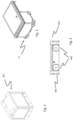
- Figure 4 describes a wheel base of a delivery vehicle.
- the delivery vehicles comprise a base with the same setup of wheels as on the container handling vehicles.
- the wheel base unit features a wheel arrangement having a first set of wheels for movement in a first direction upon a rail grid (i.e. any of the top rail grid and the transfer rail grid) and a second set of wheels for movement in a second direction perpendicular to the first direction.
- Each set of wheels comprises two pairs of wheels arranged on opposite sides of the wheel base unit.
- one of the sets of wheels is connected to a wheel displacement assembly.
- the wheel displacement assembly is able to lift and lower the connected set of wheels relative to the other set of wheels such that only the set of wheels travelling in a desired direction is in contact with the rail grid.
- the wheel displacement assembly is driven by an electric motor.
- two electric motors powered by a rechargeable battery, are connected to the set of wheels to move the wheel base unit in the desired direction.
- the horizontal periphery of the wheel base unit is dimensioned to fit within the horizontal area defined by a grid cell of the rail grid such that two-wheel base units may pass each other on any adjacent grid cells of the rail grid.
- the wheel base unit may have a footprint, i.e. an extent in the X and Y directions, which is generally equal to the horizontal area of a grid cell, i.e. the extent of a grid cell in the X and Y directions, e.g. as is described in WO2015/193278A1 .
- WO 2019/206672 A2 which the EPO identified in the examination procedure as the 'closest prior art', describes, in accordance with its abstract, a support vehicle for performing support operations in an automated storage and retrieval system. It comprises a vehicle body. It comprises a drive system comprising wheels provided in a lower part of the vehicle body, where the drive system being configured to drive the support vehicle along a track system of the automated storage and retrieval system. It comprises a connection system provided on a first side of the support vehicle. The connection system comprises a connector member protruding through a aperture of the vehicle body. The connection system comprises an actuator for moving the connector member in the aperture in relation to the vehicle body.
- the present invention also relates to an automated storage and retrieval system..
- US2015066283A1 describes, in accordance with its abstract, a human transport device and associated system to transport a user within an active workspace.
- the human transport device may include a platform to support a user, an enclosure coupled to the platform to surround the user, a drive subsystem to power the human transport device, and a control unit to control the movement of the human transport device in coordination with active mobile drive units moving within the workspace.
- a system implementing one or more human transport devices may include a management module to direct the movement of the one or more human transport devices and designate one or more areas within the workspace as protected areas. Unauthorized objects may be prohibited from entering the protected areas while the human transport device may be allowed within the protected areas.
- a problem with present day solutions of automated storage and retrieval systems is if one of the container handling vehicles breaks down on the grid there is a problem with retrieving it.
- One used solution is a chair with wheels that an operator sits on and manoeuvres by hand out to the container handling vehicle that has broken down. Using this solution, the operator must transport the container handling vehicle that has broken down back to the service area using man power.
- a service vehicle provides a platform for servicing a container handling vehicle, while on a grid-based rail system of a three-dimensional storage grid of an automated storage system for storing storage containers, wherein the service vehicle comprises two or more wheel modules, each module having a first set of wheels configured to move the vehicle along a first lateral direction (X) of the grid-based rail system and a second set of wheels configured to move the vehicle along a second lateral direction (Y) of the grid-based rail system, the second direction (Y) being perpendicular to the first direction (X), wherein a platform is mounted on the two or more wheel modules and said platform comprises an enclosure that has at least one opening that can be closed by a barrier, and the platform has a set of tracks matching the width of the tracks on the grid.
- the platform of the service vehicle is supported on at least two wheel modules.
- the wheel modules may be configured to work together as one master wheel module and one or more slave wheel modules.
- the service vehicle may have a platform configured such that a container handling vehicle may be lifted onto the platform by hand, by an operator on the service vehicle.
- the service vehicle may have a bay that can hold a container handling vehicle while the service vehicle is on the grid.
- the platform of the service vehicle may be sized to accommodate at least one operator using a set of controls, wherein an operator on the service vehicle can control the movement of the service vehicle using the set of controls.
- the service vehicle may be controlled by a central control center.
- the platform may be mounted to the upper surfaces of the wheel modules, for example, four wheel modules each positioned at a corner of the platform, and may comprise a bay for a container handling vehicle that is suspended between the wheel modules.
- the bay of the service vehicle may comprise part of the platform, for example, a part that is positioned, or can be positioned, lower than the remainder of the platform.
- the bay may be at a working level substantially corresponding to that of a base of the wheel modules. In this way a panel forming the bay may be positioned with a lower surface as close as possible to the upper surface of the rail system while still ensuring clearance and an upper surface which is only a few millimeters higher depending on the thickness of the panel.
- the bay may also be mounted to allow it to be lowered to rest on the rail system when it is position next to the container handling vehicle.
- the service vehicle may comprise a bay in the form of a recess provided in the platform that is sized to fit around the container handling vehicle.
- the recess may comprise a rectangular cut-out of a size corresponding to one or two grid cells.
- the wheel modules of the service vehicle may be all of the same type. They may each have a perimeter which corresponds substantially to that of a grid cell of the underlying grid rail system. Each wheel module may comprise a rectangular body provided with eight wheels positioned in pairs on four sides of the body, all arranged within a perimeter of one grid cell. Wheels of one wheel module may be positioned so as to ride in a first track of a double track rail and pass, with a clearance, a wheel module in an adjacent grid cell that has wheels in a second track of the same double track rail. Each wheel module may be of a height which is only marginally taller than that of the wheels. For example, each wheel module may be of a height which is less than half that of the container handling vehicle it is intended to service.
- the barrier may include an automated mechanism that prevents the barrier from being opened while the service vehicle is in motion.
- the service vehicle may be provided with a communications device that can communicate with a communications device of a container handling vehicle and wherein the communications device of the container handling vehicle may be a wireless communications device.
- the service vehicle may have further a power connector configured to provide power to a container handling vehicle.
- a further embodiment of the present invention may be configured in a system comprising a container handling vehicle and the service vehicle of any of the preceding statements, wherein the container handling vehicle may comprise a receiver and the service vehicle may comprise a transmitter.
- the container handling vehicle may be configured to receive remote control signals from the transmitter and to manoeuvre the container handling vehicle in response to those remote-control signals.
- the service vehicle may be configured such that the platform that is mounted to the wheel modules can be turned 360° in either direction around a vertical axis and relative to the wheel modules.
- a slewing bearing may be placed between the service platform and the wheel modules and used to allow the service platform to rotate freely in either direction relative to the wheel modules.
- An electric motor may control the rotation of the platform.
- the service vehicle may comprise a section of the platform with a height adjuster to lower the section onto rails of the grid.
- the height adjuster may be either a rack and pinion system or a set of hydraulic lifters.
- a method for servicing a container handling vehicle using a service vehicle in an automated storage system comprising a three-dimensional storage grid with a grid-based rail system for storing storage containers, wherein the service vehicle comprises two or more wheel modules, each module having a first set of wheels configured to move the vehicle along a first lateral direction (X) of the grid-rail system, and a second set of wheels configured to move the vehicle along a second lateral direction (Y) of the grid-based rail system, the second direction (Y) being perpendicular to the first direction (X), the service vehicle comprising a platform mounted on the two or more wheel modules, the platform comprising an enclosure that has at least one opening that can be closed by a barrier, and the platform has a set of tracks matching the width of the tracks on the grid, wherein said method comprises the steps of maneuvering the service vehicle along the grid to a location at which the opening of the enclosure is positioned next to the container handling vehicle, opening the barrier of the service vehicle, either manually lifting the container handling vehicle onto the
- the container handling vehicle rail system 108 allows the container handling vehicles 201 to move horizontally between different grid locations, where each grid location is associated with a grid cell 122.
- the storage grid 104 is shown with a height of eight grid cells 122. It is understood, however, that the storage grid 104 can in principle be of any size.
- the storage grid 104 can be considerably wider and/or longer than disclosed in fig. 1 .
- the grid 104 may have a horizontal extent of more than 700x700 storage columns 105.
- the grid 104 can be considerably deeper than disclosed in fig. 1 .
- the storage grid 104 may be more than twelve grid cells 122 deep, i.e. in the Z direction indicated in Fig. 1 .
- Fig. 2 is a perspective view of a prior art container handling vehicle having a centrally arranged cavity for containing storage containers 106 therein.
- the central cavity container handling vehicles 201 may have a footprint that covers an area with dimensions in the X and Y directions which is generally equal to the lateral extent of a grid column 112, i.e. the extent of a grid column 112 in the X and Y directions, e.g. as is described in WO2015/193278A1 .
- the central cavity container handling vehicles 101 may have a footprint which is larger than the lateral area defined by a grid column 112, e.g. as is disclosed in WO2014/090684A1 .
- Figure 3 is a perspective view of a prior art container handling vehicle having a cantilever for containing storage containers 106 underneath.
- Figure 4 describes a wheel module 401.
- the wheel module 401 may be suitable for use as a base of a delivery vehicle, for delivering storage containers on a rail system of a storage grid.
- the wheel module 401 may comprise the same setup of wheels as on the container handling vehicles.
- the wheel module 401 features a wheel arrangement having a first set of wheels 402 for movement in a first direction upon a rail grid (i.e. any of the top rail grid and the transfer rail grid) and a second set of wheels 403 for movement in a second direction perpendicular to the first direction.
- Each set of wheels comprises two pairs of wheels arranged on opposite sides of the wheel module 401.
- one of the sets of wheels is connected to a wheel displacement assembly.
- the wheel displacement assembly is able to lift and lower the connected set of wheels relative to the other set of wheels such that only the set of wheels travelling in a desired direction is in contact with the rail grid.
- the wheel displacement assembly is driven by an electric motor.
- two electric motors powered by a rechargeable battery, are connected to the set of wheels to move the wheel module 401 in the desired direction.
- the horizontal periphery of the wheel module 401 may be dimensioned to fit within the horizontal area defined by a grid cell of the rail grid such that two wheel modules 401 may pass each other on any adjacent grid cell of the rail grid.
- the wheel module 401 may have a footprint, i.e. an extent in the X and Y directions, which is generally equal to the horizontal area of a grid cell, i.e. the extent of a grid cell in the X and Y directions, e.g. as is described in WO2015/193278A1 .
- Each wheel of a set of wheels may be arranged to run along a track of a double-track rail that extends along an edge of a grid cell.
- the second track of the rail may allow a vehicle to pass in a neighboring grid cell with a clearance between the two vehicles.
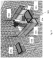
- FIG 5 is a perspective drawing of an exemplary service vehicle 501 on wheel modules 401 placed on a grid 104 with an operator 505 on board maneuvering the service vehicle 501 towards a container handling vehicle 201, 301.
- the service vehicle 501 comprises a platform 502 mounted on four wheel modules 401.
- An enclosure 503 surrounds the platform 502.
- This enclosure 503 comprises a framework of bars.
- the enclosure 503 is made of a transparent material like reinforced glass or plexiglass.
- the main purpose of the enclosure 503 is to protect the operator 505 on board the service platform 502.
- the enclosure 503 has at least one opening that allows access to a container handling vehicle. This opening has a closable barrier 504.
- the closable barrier 504 may comprise either one or more doors, e.g., either hinged doors or sliding doors.
- the barrier 504 can be in the form of a drop door.
- This drop door can have rails or tracks on the inside matching the width and shape of the rails/tracks on the grid. These rails/tracks make it possible to roll the container handling vehicle onboard the service vehicle 501.
- the barrier e.g., in the form of a door has an automatic locking mechanism that ensures that the door cannot be opened while the service vehicle 501 is in motion. A typical scenario of events is that the service vehicle 501 is maneuvered towards the container handling vehicle in question.
- the doors are ordinary hinged doors or sliding doors, the doors are opened when the service vehicle 501 is positioned next to the container handling vehicle and the container handling vehicle is lifted onto the service vehicle 501.
- the service vehicle 501 has a drop-down door, the door is dropped down onto the grid. The door is positioned such that the upper most edge of the door is next to the container handling vehicle when it is dropped down.
- the vehicle is then lifted onto the door and maneuvered, using hand power, on to the platform 502 of the service vehicle 501.
- the service can be performed while the service platform 502 is on the grid and the container handling vehicle is placed back on the grid. Alternatively, the container handling vehicle can be transported back to a service station for further repair.
- the service platform 502 can communicate either wirelessly with the container handling vehicle, or the operator 505 can connect the service vehicle 501 directly to the container handling vehicle if it is not possible to communicate wirelessly.
- the operator 505 on the service vehicle 501 can then remote control the container handling vehicle.
- the platform 502 is mounted on four wheel modules 401, the number of modules can vary, there can be any number of modules from two and up. If two wheel modules are used the service platform and the wheel modules may take up 3 grid cells. If four wheel modules are used, the service platform and the wheel modules can take up anything from 4 grid cells and up and having either a square or rectangular size. Additional number of wheel modules can be used if a longer or wider service vehicle is used.
- FIG 6 is a perspective view of the service vehicle 501 of Figure 5 comprising a service platform 502 supported on wheel modules 401 with the barrier 504 open to gain access to the container handling vehicle.
- the service vehicle 501 has reached the container handling vehicle that has broken down.
- the operator 505 has opened the barrier 504 of the enclosure 503 to gain access to the container handling vehicle.
- the operator 505 can lift the container handling vehicle onboard the service platform 502 of the service vehicle 501.
- the operator 505 can either fix the container handling vehicle on the grid or he/she can transport it back to a service station.
- There is a benefit for fixing the container handling vehicle on the grid The benefit is that the container handling vehicle can start operating where it stopped after it has been fixed.
- Figure 7 is a perspective view of the service vehicle 501 of Figure 5 comprising a service platform 502 on wheel modules 401 where the operator 505 of the platform 502 transfers the container handling robot onto the platform 502.
- the operator 505 can either lift the container handling vehicle onto the platform 502 or the operator 505 can connect to the container handling vehicle either wired or wirelessly and remotely control the container handling vehicle onto the platform 502.
- Figure 8 is a perspective view of the service vehicle 501 of Figure 5 where the container handling vehicle is onboard the platform 502.
- the platform 502 may be equipped with guiding tracks/rails 801 to ease the access of the container handling vehicle onto the platform 502. After the first set of wheels of the container handling vehicle has been lifted onto the track/rails in the platform 502, it can be pushed easily all the way in.
- the service vehicle 501 comprises four wheel modules 401 for transporting the operator on the grid. To these wheel modules 401 there is mounted a platform 502.
- the platform 502 has two zones where the operator(s) 505 are situated, suitable for two operators. Between the two zones where the operators 505 are seated there is a space or bay for the container handling vehicle.
- the space or bay for the container handling vehicle is positioned lower down than the rest of the platform 502. This is in order to make it easier to get the container handling vehicle onto the platform 502.
- the space or bay for the container handling vehicle can be lowered in order to accommodate the container handling vehicle. During travel and when the operator 505 is working on the container handling vehicle the space for accommodating the container handling vehicle can be lifted.
- the lifting and lowering of the platform 502 can be done, for example, by a rack and pinion system, hydraulics or electrical actuators.
- Figure 9 is a perspective view of another embodiment of the service vehicle where the platform 502 is placed on wheel modules 401 and has a bay 901 in the form of a recess into which the container handling vehicle fits.
- the bay 901 of the service vehicle 501 is of such a size that the container handling vehicle fits into the bay 901 with the barrier closed.
- the benefit of using a bay 901 in the form of a recess is that there is no lifting and movement of the container handling vehicle before repairing it, and the container handling vehicle can continue its operation from the exact same place it stopped. Further the bay 901 in the form of a recess is beneficial since it allows the operator 505 to safely repair the container handling vehicle while the rest of the grid is still operating.
- the platform 502 can be turned 360° in either direction around a vertical axis and relative to the wheel modules 401.
- the platform 502 can be turned relative to the wheel modules 401 using a slewing bearing mounted between the wheel modules 401 and the platform 502.
- the bearing can be turned by an electric motor.
- the electric motor turning the platform 502 relative to the wheel modules 401 can get its power from a set of rechargeable power sources mounted on the service vehicle 501.
- the wheel modules 401 can be connected using a master and slave solution.
- the master/slave configuration is used for load sharing purposes when two identical motors connected to two different drives are coupled to a common load.
- One drive is defined as the master and is configured for running in the speed-control mode whereas the other defined as slave is configured for running in torque-control mode.
Landscapes
- Engineering & Computer Science (AREA)
- Mechanical Engineering (AREA)
- Transportation (AREA)
- Chemical & Material Sciences (AREA)
- Combustion & Propulsion (AREA)
- Warehouses Or Storage Devices (AREA)
- Vehicle Cleaning, Maintenance, Repair, Refitting, And Outriggers (AREA)
Claims (24)
- Servicefahrzeug (501), das eine Plattform (502) zum Warten eines Container-Umschlagfahrzeugs (201, 301) bereitstellt, während es sich auf einem gitterbasierten Schienensystem eines dreidimensionalen Lagergitters (104) eines automatisierten Lagersystems (1) zum Lagern von Lagerbehältern (106) befindet, wobei das Servicefahrzeug (501) zwei oder mehr Radmodule umfasst, wobei jedes Modul einen ersten Satz von Rädern aufweist, die dazu ausgelegt sind, das Fahrzeug entlang einer ersten Querrichtung (X) des gitterbasierten Schienensystems zu bewegen, und einen zweiten Satz von Rädern, die dazu ausgelegt sind, das Fahrzeug entlang einer zweiten Querrichtung (Y) des gitterbasierten Schienensystems zu bewegen, wobei die zweite Richtung (Y) senkrecht zu der ersten Richtung (X) ist, wobei eine Plattform (502) an den zwei oder mehr Radmodulen montiert ist, dadurch gekennzeichnet, dass die Plattform (502) ein Gehäuse (503) umfasst, das mindestens eine Öffnung aufweist, die durch eine Barriere (504) verschlossen werden kann, und die Plattform (502) einen Satz von Schienen (801) aufweist, die der Breite der Schienen auf dem Gitter (104) entsprechen.
- Servicefahrzeug (501) nach Anspruch 1, wobei die Radmodule dazu ausgelegt sind, als ein Master-Radmodul und ein oder mehrere Slave-Radmodule zusammenzuarbeiten.
- Servicefahrzeug (501) nach Anspruch 1 oder 2, wobei das Servicefahrzeug (501) eine Plattform (502) aufweist, die so ausgelegt ist, dass ein Container-Umschlagfahrzeug (201, 301) von Hand durch einen Bediener (505) an dem Servicefahrzeug (501) auf die Plattform (502) angehoben werden kann.
- Servicefahrzeug (501) nach einem der vorhergehenden Ansprüche, wobei das Servicefahrzeug (501) eine Bucht (901) in der Form einer in der Plattform bereitgestellten Aussparung aufweist, die so bemessen ist, dass sie um ein Container-Umschlagfahrzeug (201, 301) passt und dieses hält, während sich das Servicefahrzeug (501) auf dem Gitter (104) befindet.
- Servicefahrzeug (501) nach einem der vorhergehenden Ansprüche, wobei die Plattform (502) des Servicefahrzeugs (501) auf mindestens zwei Radmodulen (401), optional vier Radmodulen (401), gestützt ist.
- Servicefahrzeug (501) nach einem der vorhergehenden Ansprüche, wobei die Plattform (502) des Servicefahrzeugs (501) so bemessen ist, dass sie mindestens einen Bediener (505) unterbringt.
- Servicefahrzeug (501) nach einem der vorhergehenden Ansprüche, das einen Satz von Bedienelementen (902) umfasst, wobei ein Bediener (505) an dem Servicefahrzeug (501) die Bewegung des Servicefahrzeugs (501) unter Verwendung des Satzes von Bedienelementen (902) steuern kann.
- Servicefahrzeug (501) nach einem der Ansprüche 1 bis 7, wobei das Servicefahrzeug (501) durch eine Steuerzentrale gesteuert wird.
- Servicefahrzeug (501) nach einem der vorhergehenden Ansprüche, wobei die Barriere (504) einen automatisierten Mechanismus aufweist, der verhindert, dass die Barriere (504) geöffnet wird, während sich das Servicefahrzeug (501) in Bewegung befindet.
- Servicefahrzeug (501) nach einem der vorhergehenden Ansprüche, wobei das Servicefahrzeug (501) mit einer Kommunikationsvorrichtung versehen ist, die mit einer Kommunikationsvorrichtung eines Container-Umschlagfahrzeugs (201, 301) kommunizieren kann.
- Servicefahrzeug (501) nach Anspruch 10, wobei die Kommunikationsvorrichtung des Container-Umschlagfahrzeugs (201, 301) eine drahtlose Kommunikationsvorrichtung ist.
- Servicefahrzeug (501) nach einem der vorhergehenden Ansprüche, wobei das Servicefahrzeug (501) einen Stromanschluss aufweist, der dazu ausgelegt ist, ein Container-Umschlagfahrzeug (201, 301) mit Strom zu versorgen.
- Servicefahrzeug (501) nach einem der vorhergehenden Ansprüche, das so ausgelegt ist, dass die auf dem Fahrgestell (401) montierte Plattform (502) um 360° in jede Richtung um eine vertikale Achse und relativ zu den Radmodulen (401) gedreht werden kann.
- Servicefahrzeug (501) nach Anspruch 13, wobei ein Schwenklager zwischen der Serviceplattform und den Radmodulen platziert ist und verwendet wird, um zu ermöglichen, dass sich die Serviceplattform in jeder Richtung relativ zu den Radmodulen frei dreht.
- Serviceplattform nach Anspruch 13 oder 14, wobei ein Elektromotor die Drehung der Plattform in jeder Richtung um eine vertikale Achse und relativ zu den Radmodulen steuert.
- Servicefahrzeug (501) nach einem der vorhergehenden Ansprüche, wobei ein Abschnitt der Plattform (502) einen Höheneinsteller umfasst, um den Abschnitt auf Schienen des Gitters (104) abzusenken.
- Servicefahrzeug (501) nach Anspruch 16, wobei der Höheneinsteller entweder ein Zahnstangensystem oder ein Satz elektronischer Aktuatoren ist.
- System, das ein Container-Umschlagfahrzeug und das Servicefahrzeug (501) nach einem der vorhergehenden Ansprüche umfasst, wobei das Container-Umschlagfahrzeug einen Empfänger umfasst und das Servicefahrzeug (501) einen Sender umfasst, wobei das Container-Umschlagfahrzeug dazu ausgelegt ist, Fernsteuersignale von dem Sender zu empfangen und das Container-Umschlagfahrzeug als Reaktion auf diese Fernsteuersignale zu manövrieren.
- Verfahren zum Warten eines Container-Umschlagfahrzeugs (201, 301) unter Verwendung eines Servicefahrzeugs (501) in einem automatisierten Lagersystem (1), das ein dreidimensionales Lagergitter (104) mit einem gitterbasierten Schienensystem zum Lagern von Lagerbehältern (106) umfasst, wobei das Servicefahrzeug (501) zwei oder mehr Radmodule umfasst, wobei jedes Modul einen ersten Satz von Rädern aufweist, die dazu ausgelegt sind, das Fahrzeug entlang einer ersten Querrichtung (X) des Gitterschienensystems zu bewegen, und einen zweiten Satz von Rädern, die dazu ausgelegt sind, das Fahrzeug entlang einer zweiten Querrichtung (Y) des gitterbasierten Schienensystems zu bewegen, wobei die zweite Richtung (Y) senkrecht zu der ersten Richtung (X) ist, wobei das Servicefahrzeug eine Plattform umfasst, die auf den zwei oder mehr Radmodulen montiert ist, wobei die Plattform ein Gehäuse umfasst, das mindestens eine Öffnung aufweist, die durch eine Barriere verschlossen werden kann, und die Plattform (502) einen Satz von Schienen (801) aufweist, die mit der Breite der Schienen auf dem Gitter (104) übereinstimmen, wobei das Verfahren die folgenden Schritte umfasst:a. Manövrieren des Servicefahrzeugs (501) entlang des Gitters zu einer Stelle, an der die Öffnung zu dem Gehäuse neben dem Container-Umschlagfahrzeug positioniert ist;b. Öffnen der Barriere (504) des Servicefahrzeugs (501);c. entweder manuelles Anheben des Container-Umschlagfahrzeugs auf die Plattform (502) oder Antreiben des Container-Umschlagfahrzeugs auf die Plattform (502) des Servicefahrzeugs (501), so dass das Container-Umschlagfahrzeug auf dem Servicefahrzeug (501) aufgenommen wird,d. Schließen der Barriere (504) des Servicefahrzeugs (501).
- Verfahren nach Anspruch 19, wobei ein Bediener (505), der sich auf dem Servicefahrzeug (501) befindet, das Servicefahrzeug (501) manövriert.
- Verfahren nach Anspruch 19, wobei eine Steuerzentrale das Servicefahrzeug (501) manövriert.
- Verfahren nach Anspruch 20, 21, wobei die Tür (504) nicht geöffnet werden kann, während sich das Servicefahrzeug (501) in Bewegung befindet.
- Verfahren nach einem der Ansprüche 20 bis 22, wobei die Kommunikationsvorrichtung des Container-Umschlagfahrzeugs (201, 301) eine drahtlose Kommunikationsvorrichtung ist.
- Verfahren nach einem der Ansprüche 20 bis 23, wobei das Container-Umschlagfahrzeug (201, 301) Strom von dem Servicefahrzeug (501) empfängt, wenn es sich auf der Plattform (502) des Servicefahrzeugs (501) befindet.
Priority Applications (1)
| Application Number | Priority Date | Filing Date | Title |
|---|---|---|---|
| EP24204837.9A EP4470942A3 (de) | 2019-12-03 | 2020-12-01 | Servicefahrzeug mit drohnenbasen |
Applications Claiming Priority (2)
| Application Number | Priority Date | Filing Date | Title |
|---|---|---|---|
| NO20191426A NO346795B1 (en) | 2019-12-03 | 2019-12-03 | Service vehicle providing a platform and method for servicing a container handling vehicle using the service vehicle. |
| PCT/EP2020/083998 WO2021110616A1 (en) | 2019-12-03 | 2020-12-01 | Service vehicle with drone bases |
Related Child Applications (2)
| Application Number | Title | Priority Date | Filing Date |
|---|---|---|---|
| EP24204837.9A Division-Into EP4470942A3 (de) | 2019-12-03 | 2020-12-01 | Servicefahrzeug mit drohnenbasen |
| EP24204837.9A Division EP4470942A3 (de) | 2019-12-03 | 2020-12-01 | Servicefahrzeug mit drohnenbasen |
Publications (3)
| Publication Number | Publication Date |
|---|---|
| EP4069608A1 EP4069608A1 (de) | 2022-10-12 |
| EP4069608B1 true EP4069608B1 (de) | 2025-06-18 |
| EP4069608C0 EP4069608C0 (de) | 2025-06-18 |
Family
ID=73694990
Family Applications (2)
| Application Number | Title | Priority Date | Filing Date |
|---|---|---|---|
| EP24204837.9A Pending EP4470942A3 (de) | 2019-12-03 | 2020-12-01 | Servicefahrzeug mit drohnenbasen |
| EP20817266.8A Active EP4069608B1 (de) | 2019-12-03 | 2020-12-01 | Servicefahrzeug für automatisiertes lagersystem |
Family Applications Before (1)
| Application Number | Title | Priority Date | Filing Date |
|---|---|---|---|
| EP24204837.9A Pending EP4470942A3 (de) | 2019-12-03 | 2020-12-01 | Servicefahrzeug mit drohnenbasen |
Country Status (10)
| Country | Link |
|---|---|
| US (2) | US12060042B2 (de) |
| EP (2) | EP4470942A3 (de) |
| JP (1) | JP7653991B2 (de) |
| KR (1) | KR20220104246A (de) |
| CN (3) | CN119527757A (de) |
| CA (1) | CA3160041A1 (de) |
| ES (1) | ES3036590T3 (de) |
| NO (1) | NO346795B1 (de) |
| PL (1) | PL4069608T3 (de) |
| WO (1) | WO2021110616A1 (de) |
Cited By (1)
| Publication number | Priority date | Publication date | Assignee | Title |
|---|---|---|---|---|
| US20230373537A1 (en) * | 2020-11-23 | 2023-11-23 | Autostore Technology AS | A service vehicle with a vehicle pen |
Families Citing this family (10)
| Publication number | Priority date | Publication date | Assignee | Title |
|---|---|---|---|---|
| GB201616559D0 (en) * | 2016-09-29 | 2016-11-16 | Ocado Innovation Limited | Robotic processing system and method |
| ES3017459T3 (en) * | 2018-12-20 | 2025-05-13 | Autostore Tech As | A container accessing station for an automated storage and retrieval system |
| US12110178B2 (en) * | 2020-07-17 | 2024-10-08 | Intelligrated Headquarters, Llc | High density storage and retrieval system |
| NO348030B1 (en) | 2022-11-29 | 2024-06-24 | Autostore Tech As | Service vehicle with a center drive unit, system and method for operating service vehicle |
| NO20221350A1 (en) * | 2022-12-16 | 2024-06-17 | Autostore Tech As | An automated storage and retrieval system with logically operable barriers for safe enter and exit into a transport vehicle, and an associated method |
| NO20221352A1 (en) * | 2022-12-16 | 2024-06-17 | Autostore Tech As | An automated storage and retrieval system comprising a vehicle pen and a transport vehicle, and an associated methods |
| NO20221348A1 (en) * | 2022-12-16 | 2024-06-17 | Autostore Tech As | An automated storage and retrieval system comprising lockable barriers for safe transfer of persons into a transport vehicle on a live grid, and associated method |
| WO2025157374A1 (en) * | 2024-01-22 | 2025-07-31 | Autostore Technology AS | Robotic picking vehicle, and associated system and method |
| EP4588846A1 (de) * | 2024-01-22 | 2025-07-23 | Autostore Technology As | Dienstsystem |
| EP4588839A1 (de) * | 2024-01-22 | 2025-07-23 | Autostore Technology As | Speichersystem |
Family Cites Families (17)
| Publication number | Priority date | Publication date | Assignee | Title |
|---|---|---|---|---|
| US3800963A (en) * | 1972-12-04 | 1974-04-02 | E Holland | Material storage and handling system |
| NO317366B1 (no) | 1999-07-01 | 2004-10-18 | Autostore As | Lagringsanlegg med fjernstyrte vogner med to hjulsett og heisinnretning for drift på skinner anlagt i kryss over kolonner av lagringsenheter som er adskilt med vertikale profilstolper |
| FR2919591B1 (fr) * | 2007-08-02 | 2009-11-27 | Savoye | Plateforme mobile de depannage pour magasin de stockage automatise |
| EP2323006B1 (de) * | 2009-11-13 | 2013-01-09 | Telejet Kommunikations GmbH | Lagersysteme mit Traktoren und Anhängern |
| NO335839B1 (no) | 2012-12-10 | 2015-03-02 | Jakob Hatteland Logistics As | Robot for transport av lagringsbeholdere |
| CN103407203B (zh) * | 2013-08-02 | 2015-10-28 | 广东正迪科技股份有限公司 | 一种在线加纤维覆膜的防伪标签制作装置及方法 |
| GB201404870D0 (en) * | 2014-03-18 | 2014-04-30 | Ocado Ltd | Robotic service device and handling method |
| US9280157B2 (en) * | 2013-09-04 | 2016-03-08 | Amazon Technologies, Inc. | System and method for transporting personnel within an active workspace |
| NO337544B1 (no) | 2014-06-19 | 2016-05-02 | Jakob Hatteland Logistics As | Fjernstyrt kjøretøysammenstilling for å plukke opp lagringsbeholdere fra et lagringssystem |
| PT3283712T (pt) * | 2015-04-15 | 2019-05-28 | Ocado Innovation Ltd | Dispositivo de estacionamento robótico e método de manipulação |
| NO340577B1 (en) * | 2015-09-04 | 2017-05-15 | Jakob Hatteland Logistics As | Method for fetching a target bin stored in a storage system and a storage system which includes a control device operating in accordance with the method |
| EP3419918B1 (de) * | 2016-02-26 | 2021-10-27 | Baumüller Nürnberg GmbH | Regalbediengerät für einen parallelen betrieb eines hochregallagers sowie ein betriebsverfahren hierfür |
| WO2019084336A1 (en) * | 2017-10-27 | 2019-05-02 | Berkshire Grey, Inc. | SYSTEMS AND METHODS FOR PROVIDING AND REMOVING CONTAINERS FOR EXCHANGING CONTAINERS OF OBJECTS USING MOBILE MATRIX SUPPORT SYSTEMS |
| JP6863263B2 (ja) * | 2017-12-18 | 2021-04-21 | 株式会社ダイフク | 物品収納設備 |
| CN207956780U (zh) * | 2017-12-25 | 2018-10-12 | 徐工集团工程机械有限公司 | 输送平台和输送平台车 |
| NO344995B1 (en) * | 2018-04-26 | 2020-08-17 | Autostore Tech As | Support vehicle for performing support operations in an automated storage and retrieval system |
| CN109292343A (zh) | 2018-11-15 | 2019-02-01 | 山东大学 | 基于仓储机器人的多层穿梭车仓储输送系统及输送方法 |
-
2019
- 2019-12-03 NO NO20191426A patent/NO346795B1/no unknown
-
2020
- 2020-12-01 WO PCT/EP2020/083998 patent/WO2021110616A1/en not_active Ceased
- 2020-12-01 PL PL20817266.8T patent/PL4069608T3/pl unknown
- 2020-12-01 CN CN202411852339.4A patent/CN119527757A/zh active Pending
- 2020-12-01 JP JP2022532774A patent/JP7653991B2/ja active Active
- 2020-12-01 CA CA3160041A patent/CA3160041A1/en active Pending
- 2020-12-01 US US17/781,860 patent/US12060042B2/en active Active
- 2020-12-01 CN CN202080083932.0A patent/CN114761336B/zh active Active
- 2020-12-01 EP EP24204837.9A patent/EP4470942A3/de active Pending
- 2020-12-01 EP EP20817266.8A patent/EP4069608B1/de active Active
- 2020-12-01 KR KR1020227022039A patent/KR20220104246A/ko active Pending
- 2020-12-01 CN CN202411852348.3A patent/CN119527758A/zh active Pending
- 2020-12-01 ES ES20817266T patent/ES3036590T3/es active Active
-
2024
- 2024-06-26 US US18/755,353 patent/US20240343229A1/en active Pending
Cited By (1)
| Publication number | Priority date | Publication date | Assignee | Title |
|---|---|---|---|---|
| US20230373537A1 (en) * | 2020-11-23 | 2023-11-23 | Autostore Technology AS | A service vehicle with a vehicle pen |
Also Published As
| Publication number | Publication date |
|---|---|
| NO346795B1 (en) | 2023-01-16 |
| CN114761336B (zh) | 2025-01-03 |
| JP7653991B2 (ja) | 2025-03-31 |
| WO2021110616A1 (en) | 2021-06-10 |
| US20230014506A1 (en) | 2023-01-19 |
| CA3160041A1 (en) | 2021-06-10 |
| EP4470942A3 (de) | 2025-03-05 |
| CN119527758A (zh) | 2025-02-28 |
| JP2023504631A (ja) | 2023-02-06 |
| CN114761336A (zh) | 2022-07-15 |
| EP4069608A1 (de) | 2022-10-12 |
| EP4069608C0 (de) | 2025-06-18 |
| US20240343229A1 (en) | 2024-10-17 |
| PL4069608T3 (pl) | 2025-10-20 |
| KR20220104246A (ko) | 2022-07-26 |
| US12060042B2 (en) | 2024-08-13 |
| CN119527757A (zh) | 2025-02-28 |
| NO20191426A1 (en) | 2021-06-04 |
| EP4470942A2 (de) | 2024-12-04 |
| ES3036590T3 (en) | 2025-09-22 |
Similar Documents
| Publication | Publication Date | Title |
|---|---|---|
| EP4069608B1 (de) | Servicefahrzeug für automatisiertes lagersystem | |
| US12240697B2 (en) | Vehicle for an automated storage and retrieval system | |
| EP4058384B1 (de) | Rettungssystem und verfahren zur bergung eines defekten fahrzeugs aus einem schienensystem | |
| EP3713855B1 (de) | Automatisiertes lager- und entnahmesystem | |
| EP4247735B1 (de) | Servicefahrzeug mit einem fahrzeugstift | |
| HK40073300A (en) | Service vehicle with drone bases | |
| HK40101984A (en) | An automated storage and retrieval system with a vehicle pen and a method of moving a vehicle between a first area and a second area of an automated storage an retrieval system | |
| HK40067341A (en) | Rescue system and methods for retrieving a malfunctioning vehicle from a rail system |
Legal Events
| Date | Code | Title | Description |
|---|---|---|---|
| STAA | Information on the status of an ep patent application or granted ep patent |
Free format text: STATUS: UNKNOWN |
|
| STAA | Information on the status of an ep patent application or granted ep patent |
Free format text: STATUS: THE INTERNATIONAL PUBLICATION HAS BEEN MADE |
|
| PUAI | Public reference made under article 153(3) epc to a published international application that has entered the european phase |
Free format text: ORIGINAL CODE: 0009012 |
|
| STAA | Information on the status of an ep patent application or granted ep patent |
Free format text: STATUS: REQUEST FOR EXAMINATION WAS MADE |
|
| 17P | Request for examination filed |
Effective date: 20220621 |
|
| AK | Designated contracting states |
Kind code of ref document: A1 Designated state(s): AL AT BE BG CH CY CZ DE DK EE ES FI FR GB GR HR HU IE IS IT LI LT LU LV MC MK MT NL NO PL PT RO RS SE SI SK SM TR |
|
| DAV | Request for validation of the european patent (deleted) | ||
| DAX | Request for extension of the european patent (deleted) | ||
| 111L | Licence recorded |
Designated state(s): AL AT BE BG CH CY CZ DE DK EE ES FI FR GB GR HR HU IE IS IT LT LU LV MC MK MT NL NO PL PT RO RS SE SI SK SM TR Name of requester: OCADO INNOVATION LIMITED, GB Effective date: 20240515 Designated state(s): AL AT BE BG CH CY CZ DE DK EE ES FI FR GB GR HR HU IE IS IT LT LU LV MC MK MT NL NO PL PT RO RS SE SI SK SM TR Name of requester: OCADO GROUP PLC, GB Effective date: 20240515 Designated state(s): AL AT BE BG CH CY CZ DE DK EE ES FI FR GB GR HR HU IE IS IT LT LU LV MC MK MT NL NO PL PT RO RS SE SI SK SM TR Name of requester: OCADO SOLUTIONS LIMITED, GB Effective date: 20240515 |
|
| GRAP | Despatch of communication of intention to grant a patent |
Free format text: ORIGINAL CODE: EPIDOSNIGR1 |
|
| STAA | Information on the status of an ep patent application or granted ep patent |
Free format text: STATUS: GRANT OF PATENT IS INTENDED |
|
| GRAJ | Information related to disapproval of communication of intention to grant by the applicant or resumption of examination proceedings by the epo deleted |
Free format text: ORIGINAL CODE: EPIDOSDIGR1 |
|
| STAA | Information on the status of an ep patent application or granted ep patent |
Free format text: STATUS: REQUEST FOR EXAMINATION WAS MADE |
|
| GRAP | Despatch of communication of intention to grant a patent |
Free format text: ORIGINAL CODE: EPIDOSNIGR1 |
|
| STAA | Information on the status of an ep patent application or granted ep patent |
Free format text: STATUS: GRANT OF PATENT IS INTENDED |
|
| GRAJ | Information related to disapproval of communication of intention to grant by the applicant or resumption of examination proceedings by the epo deleted |
Free format text: ORIGINAL CODE: EPIDOSDIGR1 |
|
| RIC1 | Information provided on ipc code assigned before grant |
Ipc: B65G 1/04 20060101AFI20240801BHEP |
|
| STAA | Information on the status of an ep patent application or granted ep patent |
Free format text: STATUS: REQUEST FOR EXAMINATION WAS MADE |
|
| INTG | Intention to grant announced |
Effective date: 20240819 |
|
| INTC | Intention to grant announced (deleted) | ||
| INTG | Intention to grant announced |
Effective date: 20240903 |
|
| INTC | Intention to grant announced (deleted) | ||
| GRAP | Despatch of communication of intention to grant a patent |
Free format text: ORIGINAL CODE: EPIDOSNIGR1 |
|
| STAA | Information on the status of an ep patent application or granted ep patent |
Free format text: STATUS: GRANT OF PATENT IS INTENDED |
|
| INTG | Intention to grant announced |
Effective date: 20250404 |
|
| GRAS | Grant fee paid |
Free format text: ORIGINAL CODE: EPIDOSNIGR3 |
|
| GRAA | (expected) grant |
Free format text: ORIGINAL CODE: 0009210 |
|
| STAA | Information on the status of an ep patent application or granted ep patent |
Free format text: STATUS: THE PATENT HAS BEEN GRANTED |
|
| 111L | Licence recorded |
Designated state(s): AL AT BE BG CH CY CZ DE DK EE ES FI FR GB GR HR HU IE IS IT LT LU LV MC MK MT NL NO PL PT RO RS SE SI SK SM TR Name of requester: OCADO INNOVATION LIMITED, GB Effective date: 20240515 Designated state(s): AL AT BE BG CH CY CZ DE DK EE ES FI FR GB GR HR HU IE IS IT LT LU LV MC MK MT NL NO PL PT RO RS SE SI SK SM TR Name of requester: OCADO GROUP PLC, GB Effective date: 20240515 Designated state(s): AL AT BE BG CH CY CZ DE DK EE ES FI FR GB GR HR HU IE IS IT LT LU LV MC MK MT NL NO PL PT RO RS SE SI SK SM TR Name of requester: OCADO SOLUTIONS LIMITED, GB Effective date: 20240515 |
|
| AK | Designated contracting states |
Kind code of ref document: B1 Designated state(s): AL AT BE BG CH CY CZ DE DK EE ES FI FR GB GR HR HU IE IS IT LI LT LU LV MC MK MT NL NO PL PT RO RS SE SI SK SM TR |
|
| REG | Reference to a national code |
Ref country code: GB Ref legal event code: FG4D |
|
| REG | Reference to a national code |
Ref country code: CH Ref legal event code: EP |
|
| REG | Reference to a national code |
Ref country code: CH Ref legal event code: EP |
|
| REG | Reference to a national code |
Ref country code: IE Ref legal event code: FG4D |
|
| U01 | Request for unitary effect filed |
Effective date: 20250623 |
|
| U07 | Unitary effect registered |
Designated state(s): AT BE BG DE DK EE FI FR IT LT LU LV MT NL PT RO SE SI Effective date: 20250701 |
|
| REG | Reference to a national code |
Ref country code: ES Ref legal event code: FG2A Ref document number: 3036590 Country of ref document: ES Kind code of ref document: T3 Effective date: 20250922 |
|
| PG25 | Lapsed in a contracting state [announced via postgrant information from national office to epo] |
Ref country code: NO Free format text: LAPSE BECAUSE OF FAILURE TO SUBMIT A TRANSLATION OF THE DESCRIPTION OR TO PAY THE FEE WITHIN THE PRESCRIBED TIME-LIMIT Effective date: 20250918 Ref country code: GR Free format text: LAPSE BECAUSE OF FAILURE TO SUBMIT A TRANSLATION OF THE DESCRIPTION OR TO PAY THE FEE WITHIN THE PRESCRIBED TIME-LIMIT Effective date: 20250919 |
|
| PG25 | Lapsed in a contracting state [announced via postgrant information from national office to epo] |
Ref country code: HR Free format text: LAPSE BECAUSE OF FAILURE TO SUBMIT A TRANSLATION OF THE DESCRIPTION OR TO PAY THE FEE WITHIN THE PRESCRIBED TIME-LIMIT Effective date: 20250618 |
|
| PG25 | Lapsed in a contracting state [announced via postgrant information from national office to epo] |
Ref country code: RS Free format text: LAPSE BECAUSE OF FAILURE TO SUBMIT A TRANSLATION OF THE DESCRIPTION OR TO PAY THE FEE WITHIN THE PRESCRIBED TIME-LIMIT Effective date: 20250918 |