EP4069562B1 - Brake actuator, in particular electromechanical brake actuator of a commercial vehicle - Google Patents
Brake actuator, in particular electromechanical brake actuator of a commercial vehicle Download PDFInfo
- Publication number
- EP4069562B1 EP4069562B1 EP20819669.1A EP20819669A EP4069562B1 EP 4069562 B1 EP4069562 B1 EP 4069562B1 EP 20819669 A EP20819669 A EP 20819669A EP 4069562 B1 EP4069562 B1 EP 4069562B1
- Authority
- EP
- European Patent Office
- Prior art keywords
- brake actuator
- guiding member
- push rod
- slot
- casing
- Prior art date
- Legal status (The legal status is an assumption and is not a legal conclusion. Google has not performed a legal analysis and makes no representation as to the accuracy of the status listed.)
- Active
Links
Images



Classifications
-
- F—MECHANICAL ENGINEERING; LIGHTING; HEATING; WEAPONS; BLASTING
- F16—ENGINEERING ELEMENTS AND UNITS; GENERAL MEASURES FOR PRODUCING AND MAINTAINING EFFECTIVE FUNCTIONING OF MACHINES OR INSTALLATIONS; THERMAL INSULATION IN GENERAL
- F16D—COUPLINGS FOR TRANSMITTING ROTATION; CLUTCHES; BRAKES
- F16D65/00—Parts or details
- F16D65/14—Actuating mechanisms for brakes; Means for initiating operation at a predetermined position
- F16D65/16—Actuating mechanisms for brakes; Means for initiating operation at a predetermined position arranged in or on the brake
- F16D65/18—Actuating mechanisms for brakes; Means for initiating operation at a predetermined position arranged in or on the brake adapted for drawing members together, e.g. for disc brakes
-
- B—PERFORMING OPERATIONS; TRANSPORTING
- B60—VEHICLES IN GENERAL
- B60T—VEHICLE BRAKE CONTROL SYSTEMS OR PARTS THEREOF; BRAKE CONTROL SYSTEMS OR PARTS THEREOF, IN GENERAL; ARRANGEMENT OF BRAKING ELEMENTS ON VEHICLES IN GENERAL; PORTABLE DEVICES FOR PREVENTING UNWANTED MOVEMENT OF VEHICLES; VEHICLE MODIFICATIONS TO FACILITATE COOLING OF BRAKES
- B60T13/00—Transmitting braking action from initiating means to ultimate brake actuator with power assistance or drive; Brake systems incorporating such transmitting means, e.g. air-pressure brake systems
- B60T13/74—Transmitting braking action from initiating means to ultimate brake actuator with power assistance or drive; Brake systems incorporating such transmitting means, e.g. air-pressure brake systems with electrical assistance or drive
- B60T13/741—Transmitting braking action from initiating means to ultimate brake actuator with power assistance or drive; Brake systems incorporating such transmitting means, e.g. air-pressure brake systems with electrical assistance or drive acting on an ultimate actuator
-
- F—MECHANICAL ENGINEERING; LIGHTING; HEATING; WEAPONS; BLASTING
- F16—ENGINEERING ELEMENTS AND UNITS; GENERAL MEASURES FOR PRODUCING AND MAINTAINING EFFECTIVE FUNCTIONING OF MACHINES OR INSTALLATIONS; THERMAL INSULATION IN GENERAL
- F16D—COUPLINGS FOR TRANSMITTING ROTATION; CLUTCHES; BRAKES
- F16D55/00—Brakes with substantially-radial braking surfaces pressed together in axial direction, e.g. disc brakes
- F16D55/02—Brakes with substantially-radial braking surfaces pressed together in axial direction, e.g. disc brakes with axially-movable discs or pads pressed against axially-located rotating members
- F16D55/22—Brakes with substantially-radial braking surfaces pressed together in axial direction, e.g. disc brakes with axially-movable discs or pads pressed against axially-located rotating members by clamping an axially-located rotating disc between movable braking members, e.g. movable brake discs or brake pads
- F16D55/224—Brakes with substantially-radial braking surfaces pressed together in axial direction, e.g. disc brakes with axially-movable discs or pads pressed against axially-located rotating members by clamping an axially-located rotating disc between movable braking members, e.g. movable brake discs or brake pads with a common actuating member for the braking members
- F16D55/225—Brakes with substantially-radial braking surfaces pressed together in axial direction, e.g. disc brakes with axially-movable discs or pads pressed against axially-located rotating members by clamping an axially-located rotating disc between movable braking members, e.g. movable brake discs or brake pads with a common actuating member for the braking members the braking members being brake pads
- F16D55/2255—Brakes with substantially-radial braking surfaces pressed together in axial direction, e.g. disc brakes with axially-movable discs or pads pressed against axially-located rotating members by clamping an axially-located rotating disc between movable braking members, e.g. movable brake discs or brake pads with a common actuating member for the braking members the braking members being brake pads in which the common actuating member is pivoted
-
- F—MECHANICAL ENGINEERING; LIGHTING; HEATING; WEAPONS; BLASTING
- F16—ENGINEERING ELEMENTS AND UNITS; GENERAL MEASURES FOR PRODUCING AND MAINTAINING EFFECTIVE FUNCTIONING OF MACHINES OR INSTALLATIONS; THERMAL INSULATION IN GENERAL
- F16D—COUPLINGS FOR TRANSMITTING ROTATION; CLUTCHES; BRAKES
- F16D2121/00—Type of actuator operation force
- F16D2121/18—Electric or magnetic
- F16D2121/24—Electric or magnetic using motors
-
- F—MECHANICAL ENGINEERING; LIGHTING; HEATING; WEAPONS; BLASTING
- F16—ENGINEERING ELEMENTS AND UNITS; GENERAL MEASURES FOR PRODUCING AND MAINTAINING EFFECTIVE FUNCTIONING OF MACHINES OR INSTALLATIONS; THERMAL INSULATION IN GENERAL
- F16D—COUPLINGS FOR TRANSMITTING ROTATION; CLUTCHES; BRAKES
- F16D2125/00—Components of actuators
- F16D2125/18—Mechanical mechanisms
- F16D2125/20—Mechanical mechanisms converting rotation to linear movement or vice versa
- F16D2125/22—Mechanical mechanisms converting rotation to linear movement or vice versa acting transversely to the axis of rotation
- F16D2125/28—Cams; Levers with cams
-
- F—MECHANICAL ENGINEERING; LIGHTING; HEATING; WEAPONS; BLASTING
- F16—ENGINEERING ELEMENTS AND UNITS; GENERAL MEASURES FOR PRODUCING AND MAINTAINING EFFECTIVE FUNCTIONING OF MACHINES OR INSTALLATIONS; THERMAL INSULATION IN GENERAL
- F16D—COUPLINGS FOR TRANSMITTING ROTATION; CLUTCHES; BRAKES
- F16D2125/00—Components of actuators
- F16D2125/18—Mechanical mechanisms
- F16D2125/20—Mechanical mechanisms converting rotation to linear movement or vice versa
- F16D2125/22—Mechanical mechanisms converting rotation to linear movement or vice versa acting transversely to the axis of rotation
- F16D2125/28—Cams; Levers with cams
- F16D2125/32—Cams; Levers with cams acting on one cam follower
-
- F—MECHANICAL ENGINEERING; LIGHTING; HEATING; WEAPONS; BLASTING
- F16—ENGINEERING ELEMENTS AND UNITS; GENERAL MEASURES FOR PRODUCING AND MAINTAINING EFFECTIVE FUNCTIONING OF MACHINES OR INSTALLATIONS; THERMAL INSULATION IN GENERAL
- F16D—COUPLINGS FOR TRANSMITTING ROTATION; CLUTCHES; BRAKES
- F16D2125/00—Components of actuators
- F16D2125/18—Mechanical mechanisms
- F16D2125/58—Mechanical mechanisms transmitting linear movement
- F16D2125/582—Flexible element, e.g. spring, other than the main force generating element
-
- F—MECHANICAL ENGINEERING; LIGHTING; HEATING; WEAPONS; BLASTING
- F16—ENGINEERING ELEMENTS AND UNITS; GENERAL MEASURES FOR PRODUCING AND MAINTAINING EFFECTIVE FUNCTIONING OF MACHINES OR INSTALLATIONS; THERMAL INSULATION IN GENERAL
- F16D—COUPLINGS FOR TRANSMITTING ROTATION; CLUTCHES; BRAKES
- F16D2125/00—Components of actuators
- F16D2125/18—Mechanical mechanisms
- F16D2125/58—Mechanical mechanisms transmitting linear movement
- F16D2125/64—Levers
-
- F—MECHANICAL ENGINEERING; LIGHTING; HEATING; WEAPONS; BLASTING
- F16—ENGINEERING ELEMENTS AND UNITS; GENERAL MEASURES FOR PRODUCING AND MAINTAINING EFFECTIVE FUNCTIONING OF MACHINES OR INSTALLATIONS; THERMAL INSULATION IN GENERAL
- F16D—COUPLINGS FOR TRANSMITTING ROTATION; CLUTCHES; BRAKES
- F16D2125/00—Components of actuators
- F16D2125/18—Mechanical mechanisms
- F16D2125/58—Mechanical mechanisms transmitting linear movement
- F16D2125/70—Rods
Definitions
- the present invention relates to a brake actuator, in particular an electromechanical brake actuator of a commercial vehicle, wherein the brake actuator comprises: a casing, an electric motor for providing a driving torque, a cam disc rotatable mounted to the casing, wherein the cam disc is operatively coupled to the electric motor, a push rod received in the casing, and being configured to move back and forth in a longitudinal direction between a retracted position and an extended position, wherein the push rod and the cam disc are operatively coupled such that a rotational movement of the cam disc advances a linear movement of the push rod.
- Brake actuators of aforementioned type are known in the art. They are used in automotive industry and in particular in the truck industry.
- DE 10 2017 004 436 A1 discloses for example such an electromechanical brake actuator having a cam disc and a push rod, which have coupling surfaces in contact with each other, which slide or roll against each other for direct transmission of the drive torque between cam disc and push rod.
- DE 10 2016 2010 757 B3 shows a parking brake actuated via a cam disk, whereby the actuation takes place via a spring tappet guided in the housing of the parking brake.
- an electric motor provides a driving torque upon receiving a brake signal provided for example by a foot pedal. Said driving torque is transmitted by means of a rotational movement of the cam disc to a push rod. Advanced by the rotational movement of the cam disc, the push rod moves towards its extended position in order to transmit a braking force to a braking disc.
- the push rod and the cam disc are operatively coupled such that the rotational movement of the cam disc, advances a linear movement of the push rod. Furthermore, the rotational movement of the cam disc advances a pivoting movement in a predefined angle range. This inclination results in stresses and friction acting on the casing when the push rod is moving between its retracted and extended position, thereby potentially reducing the otherwise obtainable service life of the brake actuator.
- the invention solves the underlying problem for a brake actuator of the initially mentioned type by suggesting that a guiding member, in particular a bushing, is mounted to the casing, wherein the guiding member is configured to guide the movement of the push rod in longitudinal direction.
- a guiding member in particular a bushing
- the invention is based upon the realization that such a guiding member provides an increased wear resistance thereby protecting the casing against stresses and friction. Accordingly, in such brake actuator a cost-efficient material can be chosen for the casing.
- the guiding member has a first contact surface
- the push rod has a corresponding second contact surface that is in sliding contact with the first contact surface.
- the first contact surface is curved, preferably being part-cylindrical or cylindrical.
- sharp edges and the like are avoided thereby increasing the wear resistance and consequently the service life.
- the second contact surface has a corresponding curvature, preferably being part-spherical.
- the second contact surface has a curvature corresponding to file curvature of the first contact surface, the guidance of the push rod is further improved and the wear resistance and consequently the service life is increased as also at the second contact surface sharp edges and the like are avoided.
- the guiding member has at least one slot extending in longitudinal direction and being configured to receive the cam disc at least partially.
- the slot is a first slot and the guiding member further has a second slot extending in longitudinal direction, wherein the second slot is arranged opposite to the first slot, and wherein the first and second slots are configured to receive the cam disc at least partially.
- the first and second slots have a width that corresponds to the thickness of the cam disc.
- the contact surface for guiding push rod can be maximized, as the width of the slot reducing the contact surface is only as large as required for receiving the cam disc.
- the guiding member is at least partially arranged in the casing.
- the arrangement is more compact and the guiding member can easily be integrated in the casing.
- the guiding member is mounted to the casing in a non-positive connection, preferably in a press fit.
- a non-positive connection is a cost-effective, secure and easyto-handle solution to mount the guiding member to the casing.
- a press fit is easy to manufacture and can be integrated in the assembling of the brake actuator by pressing the guiding member into the casing before inserting the push rod in the casing.
- the brake actuator further comprises a return spring operatively coupled to the push rod, and effective to urge the push rod towards its retracted position.
- a return spring operatively coupled to the push rod, and effective to urge the push rod towards its retracted position.
- the guiding member has a first face end facing the cam disc and a second face end facing away from the cam disc, and the guiding member has a projection of the second face end extending radially inwards.
- a projection provides a sufficient mounting and/or supporting interface.
- the guiding member is more compact.
- the return spring is mounted inside the guiding member, respectively, against the projection.
- the projection provides a spring seat for the return spring.
- the guiding member is formed partially or completely of a material having a high strength and a low friction coefficient, preferably steel or high strength polymer. Hence, the wear resistance and consequently the service life is further improved.
- the brake actuator comprising: a pivot lever configured for applying a braking force on a brake disc, wherein the pivot lever and the push rod are engaged such that the linear movement of the push rod advances a pivoting movement of the lever.
- a pivot lever configured for applying a braking force on a brake disc, wherein the pivot lever and the push rod are engaged such that the linear movement of the push rod advances a pivoting movement of the lever.
- the invention has herein above been described in a first aspect with respect to a brake actuator.
- the invention also relates to the use of a guiding member in a brake actuator according to the preferred embodiments of the invention described above, wherein the casing has a first mounting interface, and the guiding member has a second mounting interface that corresponds to the first mounting interface, wherein the second mounting interface is configured to be engaged with the first mounting interface for mounting the guiding member to the casing.
- the invention solves the initially mentioned problem in that the guiding member is used to guide the movement of the push rod in the longitudinal direction.
- the wear resistance is improved thereby increasing the service life of such a brake actuator.
- the examples and preferred embodiments of the brake actuator of the first aspect as described above are also the preferred examples and preferred embodiment of the use of a guiding member for such a brake actuator and vice versa.
- the brake actuator 1 shown in Figs. 1 and 2 comprises a casing 10, a cam disc 20 rotatable mounted to the casing 10, a push rod 30 and a guiding member 40 mounted to the casing 10, wherein the push rod 30 is received in the guiding member 40.
- the brake actuator 1 further comprises a lever 50 operatively coupled to the push rod 30.
- Fig. 1 illustrates the brake actuator 1 and in particular the push rod 30 in its retracted position 300 and Fig. 2 illustrates the brake actuator 1 in its extended position 400.
- the cam disc 20 has a coupling surface 22 being slidable in contact with the push rod 30 for transmitting a driving torque applied by an electric motor (not shown) to the push rod 30.
- the push rod 30 has a rod portion 32 being operatively coupled to the lever 50 and a guiding portion 34 being slidable in contact with the guiding member 40.
- the push rod 30 and in particular the guiding portion 34 further has a contact surface 36 being in sliding contact with the guiding member 40.
- the push rod 30 has a coupling surface 38 being configured for slidable engagement with the corresponding coupling surface 22 of the cam disc 20 such that the push rod 30 is moved forth in a longitudinal direction 100 from its retracted position 300 to its extended position 400 ( Fig. 2 ).
- the guiding member 40 has a first contact surface 41 that corresponds to the contact surface 36 of the push rod 30 for being slidable in contact.
- the guiding member 40 further has a first slot 43 and a second slot 44 extending in longitudinal direction and being arranged opposite to each other.
- the first slot 43 is arranged and dimensioned such that that the cam disc 20 is at least partially received in the slot 43 when the push rod 30 is in its extended position 400 ( Fig. 2 ).
- the second slot 44 is arranged and dimensioned such that the cam disc 20 is at least partially received in the slot 44 when the push rod 30 is in its retracted position ( Fig. 1 ).
- the slots 43, 44 have a width 46 ( Fig. 5 ) that corresponds to the thickness 24 ( Fig. 5 ) of the cam disc 20.
- Figs. 3 to 6 illustrate a brake actuator 1' according to a second embodiment.
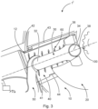
- the brake actuator 1' exemplary shown in Fig. 3 differs from the brake actuator shown in Figs. 1 and 2 by a return spring 60 operatively coupled to the push rod 30 and effective to urge the push rod 30 towards its retracted position 300.
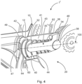
- the guiding member 40 has a first face end 48 facing the cam disc 20 and a second face end 49 facing away from the cam disc 20.
- the guiding member 40 has a projection 47 at the second face end 49 extending radially inwards.
- the return spring 60 is arranged in the guiding member 40, wherein the return spring 60 is enclosing the rod portion 32 of the push rod 30 at its lateral end 62.
- the spring seat 64 of the return spring 60 is provided by means of the projection 47, wherein the diameter of the return spring 60 tapers from the spring seat 64 provided by the projection 47 towards the push rod 30 such that the lowest diameter of the return spring 60 is provided at a lateral end 64 of the return spring 60 being engaged with the push rod 30.
- the casing 10 has a mounting interface 12 and the guiding member 40 has the mounting interface 42 such that the guiding member 40 is engaged with the casing 10 in a non-positive connection by means of a press fit.
- the contact surface 41 of the guiding member 40 is cylindrical and the contact surface 36 of the push rod 30 has a curvature that corresponds to the curvature of the contact surface 41.
- the slots 43, 44 provided at the guiding member 40 have the width 46 that corresponds to the thickness 24 of the cam disc 20, wherein the width 46 is larger than the thickness 24 such that a tolerance is provided that is required due to clearance in the rotatable coupling of the cam disc 20 and the casing 10.
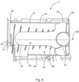
- the contact surface 36 of the push rod 30 is partially spherical enabling an inclination of the push rod 30 inside the guiding member 40 due to the rotational movement of the cam disc 20 or the pivoting movement of the lever 50.
- the outer diameter of this partially spherical contact surface 36 corresponds to the inner diameter of the contact surface 41 of the guiding member 40 such that the push rod 30 is guided in longitudinal direction 100.
Landscapes
- Engineering & Computer Science (AREA)
- General Engineering & Computer Science (AREA)
- Mechanical Engineering (AREA)
- Transportation (AREA)
- Braking Arrangements (AREA)
Description
- The present invention relates to a brake actuator, in particular an electromechanical brake actuator of a commercial vehicle, wherein the brake actuator comprises: a casing, an electric motor for providing a driving torque, a cam disc rotatable mounted to the casing, wherein the cam disc is operatively coupled to the electric motor, a push rod received in the casing, and being configured to move back and forth in a longitudinal direction between a retracted position and an extended position, wherein the push rod and the cam disc are operatively coupled such that a rotational movement of the cam disc advances a linear movement of the push rod.
- Brake actuators of aforementioned type are known in the art. They are used in automotive industry and in particular in the truck industry.
DE 10 2017 004 436 A1 -
DE 10 2016 2010 757 B3 - In brake actuators of the aforementioned type, an electric motor provides a driving torque upon receiving a brake signal provided for example by a foot pedal. Said driving torque is transmitted by means of a rotational movement of the cam disc to a push rod. Advanced by the rotational movement of the cam disc, the push rod moves towards its extended position in order to transmit a braking force to a braking disc.
- In such a brake actuator, the push rod and the cam disc are operatively coupled such that the rotational movement of the cam disc, advances a linear movement of the push rod. Furthermore, the rotational movement of the cam disc advances a pivoting movement in a predefined angle range. This inclination results in stresses and friction acting on the casing when the push rod is moving between its retracted and extended position, thereby potentially reducing the otherwise obtainable service life of the brake actuator.
- Accordingly, it has been an object of the present invention to suggest a brake actuator that overcomes the aforementioned challenges as much as possible. In particular, it has been an object to suggest a brake actuator while providing an increased wear resistance and increased service life.
- In one aspect, the invention solves the underlying problem for a brake actuator of the initially mentioned type by suggesting that a guiding member, in particular a bushing, is mounted to the casing, wherein the guiding member is configured to guide the movement of the push rod in longitudinal direction. The invention is based upon the realization that such a guiding member provides an increased wear resistance thereby protecting the casing against stresses and friction. Accordingly, in such brake actuator a cost-efficient material can be chosen for the casing.
- In a particularly preferred embodiment, the guiding member has a first contact surface, and the push rod has a corresponding second contact surface that is in sliding contact with the first contact surface. By having such contact surfaces, a low friction guiding of the movement of the push rod in longitudinal direction is provided. Such contact surfaces can for example have special coatings in order to reduce the friction and to increase the wear resistance.
- Preferably, the first contact surface is curved, preferably being part-cylindrical or cylindrical. By suggesting a curved contact surface, sharp edges and the like are avoided thereby increasing the wear resistance and consequently the service life.
- Preferably, the second contact surface has a corresponding curvature, preferably being part-spherical. By suggesting that the second contact surface has a curvature corresponding to file curvature of the first contact surface, the guidance of the push rod is further improved and the wear resistance and consequently the service life is increased as also at the second contact surface sharp edges and the like are avoided.
- In accordance to the invention, the guiding member has at least one slot extending in longitudinal direction and being configured to receive the cam disc at least partially. By providing a slot, the arrangement of the casing, the guiding member and the cam disc is more compact and the required space for the brake actuator is reduced. Further, the guiding member provides a sufficient guidance for the push rod, as the slot has no significant influence on the sliding contact of the guiding member and the push rod.
- Preferably, the slot is a first slot and the guiding member further has a second slot extending in longitudinal direction, wherein the second slot is arranged opposite to the first slot, and wherein the first and second slots are configured to receive the cam disc at least partially.
- Preferably, the first and second slots have a width that corresponds to the thickness of the cam disc. Hence, the contact surface for guiding push rod can be maximized, as the width of the slot reducing the contact surface is only as large as required for receiving the cam disc.
- Preferably, the guiding member is at least partially arranged in the casing. By arranging the guiding member at least partially in the casing, the arrangement is more compact and the guiding member can easily be integrated in the casing. Preferably, the guiding member is mounted to the casing in a non-positive connection, preferably in a press fit. Thus, the invention advantageously recognizes that a non-positive connection is a cost-effective, secure and easyto-handle solution to mount the guiding member to the casing. Especially, a press fit is easy to manufacture and can be integrated in the assembling of the brake actuator by pressing the guiding member into the casing before inserting the push rod in the casing.
- In a further preferred embodiment, the brake actuator further comprises a return spring operatively coupled to the push rod, and effective to urge the push rod towards its retracted position. By suggesting such a return spring, the invention advantageously recognizes that the guidance of the push rod and especially of a rod portion of the push rod that extends in longitudinal direction, is improved. Further, the push rod will automatically rest in its retracted position until a driving torque is applied by the electric motor.
- Preferably, the guiding member has a first face end facing the cam disc and a second face end facing away from the cam disc, and the guiding member has a projection of the second face end extending radially inwards. Such a projection provides a sufficient mounting and/or supporting interface. As the projection extends radially inwards, the guiding member is more compact. Preferably, the return spring is mounted inside the guiding member, respectively, against the projection. Thus, the projection provides a spring seat for the return spring. By mounting the return spring in said guiding member, the movement of the return spring for expanding and retracting is guided by the guiding member. Furthermore, a more compact arrangement of the return spring and the guiding member is provided, thereby reducing the building space of the brake actuator.
- Preferably, the guiding member is formed partially or completely of a material having a high strength and a low friction coefficient, preferably steel or high strength polymer. Hence, the wear resistance and consequently the service life is further improved.
- In a further preferred embodiment, the brake actuator comprising: a pivot lever configured for applying a braking force on a brake disc, wherein the pivot lever and the push rod are engaged such that the linear movement of the push rod advances a pivoting movement of the lever. Such a lever provides a sufficient transmission of the linear movement of the push rod due to the rotational movement of the cam disc to a braking disc, respectively, by urging a pair of braking pads towards the braking disc.
- The invention has herein above been described in a first aspect with respect to a brake actuator. In a second aspect, the invention also relates to the use of a guiding member in a brake actuator according to the preferred embodiments of the invention described above, wherein the casing has a first mounting interface, and the guiding member has a second mounting interface that corresponds to the first mounting interface, wherein the second mounting interface is configured to be engaged with the first mounting interface for mounting the guiding member to the casing.
- According to the second aspect, the invention solves the initially mentioned problem in that the guiding member is used to guide the movement of the push rod in the longitudinal direction. By using such a guiding member, the wear resistance is improved thereby increasing the service life of such a brake actuator. The examples and preferred embodiments of the brake actuator of the first aspect as described above are also the preferred examples and preferred embodiment of the use of a guiding member for such a brake actuator and vice versa.
- For a more complete understanding of the invention, the invention will now be described in detail with reference to the accompanying drawings. The detailed description will illustrate and describe what is considered as a preferred embodiment of the invention. It should of course be understood that various modifications and changes in form or detail could readily be made without departing from the scope of the invention as defined in the appended claims. It is therefore intended that the invention may not be limited to the exact form and detail shown and described herein, nor to anything less than the whole of the invention disclosed herein and as claimed hereinafter. Further, the features described in the description, the drawings and the claims disclosing the invention may be essential for the invention considered alone or in combination. In particular, any reference signs in the claims shall not be construed as limiting the scope of the invention. The wording "comprising" does not exclude other elements or steps. The wording "a" or "an" does not exclude a plurality. In detail:
- Fig. 1
- shows a brake actuator according to a first embodiment in a retracted position in a sectional view,
- Fig. 2
- shows the brake actuator according to
Fig. 1 in an extended position in a sectional view, - Fig. 3
- shows a brake actuator according to a second preferred embodiment in a sectional view,
- Fig. 4
- shows the brake actuator according to
Fig. 3 in a perspective sectional view, - Fig. 5
- shows the brake actuator according to
Fig. 3 in a front view, and - Fig. 6
- shows the brake actuator according to
Fig. 3 in a sectional side view. - The
brake actuator 1 shown inFigs. 1 and2 comprises acasing 10, acam disc 20 rotatable mounted to thecasing 10, apush rod 30 and a guidingmember 40 mounted to thecasing 10, wherein thepush rod 30 is received in the guidingmember 40. Thebrake actuator 1 further comprises alever 50 operatively coupled to thepush rod 30. -
Fig. 1 illustrates thebrake actuator 1 and in particular thepush rod 30 in its retractedposition 300 andFig. 2 illustrates thebrake actuator 1 in itsextended position 400. - The
cam disc 20 has acoupling surface 22 being slidable in contact with thepush rod 30 for transmitting a driving torque applied by an electric motor (not shown) to thepush rod 30. - The
push rod 30 has arod portion 32 being operatively coupled to thelever 50 and a guidingportion 34 being slidable in contact with the guidingmember 40. Thepush rod 30 and in particular the guidingportion 34 further has acontact surface 36 being in sliding contact with the guidingmember 40. Thepush rod 30 has acoupling surface 38 being configured for slidable engagement with the correspondingcoupling surface 22 of thecam disc 20 such that thepush rod 30 is moved forth in alongitudinal direction 100 from its retractedposition 300 to its extended position 400 (Fig. 2 ). - The guiding
member 40 has afirst contact surface 41 that corresponds to thecontact surface 36 of thepush rod 30 for being slidable in contact. - The guiding
member 40 further has afirst slot 43 and asecond slot 44 extending in longitudinal direction and being arranged opposite to each other. Thefirst slot 43 is arranged and dimensioned such that that thecam disc 20 is at least partially received in theslot 43 when thepush rod 30 is in its extended position 400 (Fig. 2 ). Thesecond slot 44 is arranged and dimensioned such that thecam disc 20 is at least partially received in theslot 44 when thepush rod 30 is in its retracted position (Fig. 1 ). Theslots Fig. 5 ) that corresponds to the thickness 24 (Fig. 5 ) of thecam disc 20. -
Figs. 3 to 6 illustrate a brake actuator 1' according to a second embodiment. - The brake actuator 1' exemplary shown in
Fig. 3 differs from the brake actuator shown inFigs. 1 and2 by areturn spring 60 operatively coupled to thepush rod 30 and effective to urge thepush rod 30 towards its retractedposition 300. - As in particular shown in
Fig. 4 , the guidingmember 40 has afirst face end 48 facing thecam disc 20 and asecond face end 49 facing away from thecam disc 20. The guidingmember 40 has aprojection 47 at thesecond face end 49 extending radially inwards. - The
return spring 60 is arranged in the guidingmember 40, wherein thereturn spring 60 is enclosing therod portion 32 of thepush rod 30 at itslateral end 62. Thespring seat 64 of thereturn spring 60 is provided by means of theprojection 47, wherein the diameter of thereturn spring 60 tapers from thespring seat 64 provided by theprojection 47 towards thepush rod 30 such that the lowest diameter of thereturn spring 60 is provided at alateral end 64 of thereturn spring 60 being engaged with thepush rod 30. - As shown in
Fig. 3 and4 , thecasing 10 has a mountinginterface 12 and the guidingmember 40 has the mountinginterface 42 such that the guidingmember 40 is engaged with thecasing 10 in a non-positive connection by means of a press fit. - As in particular shown in
Fig. 5 , thecontact surface 41 of the guidingmember 40 is cylindrical and thecontact surface 36 of thepush rod 30 has a curvature that corresponds to the curvature of thecontact surface 41. - The
slots member 40 have thewidth 46 that corresponds to thethickness 24 of thecam disc 20, wherein thewidth 46 is larger than thethickness 24 such that a tolerance is provided that is required due to clearance in the rotatable coupling of thecam disc 20 and thecasing 10. - As best shown in
Fig. 6 , thecontact surface 36 of thepush rod 30 is partially spherical enabling an inclination of thepush rod 30 inside the guidingmember 40 due to the rotational movement of thecam disc 20 or the pivoting movement of thelever 50. The outer diameter of this partiallyspherical contact surface 36 corresponds to the inner diameter of thecontact surface 41 of the guidingmember 40 such that thepush rod 30 is guided inlongitudinal direction 100. -
- 1
- brake actuator
- 10
- casing
- 12
- first mounting interface
- 20
- cam disc
- 22
- coupling surface
- 24
- thickness
- 30
- push rod
- 32
- rod portion
- 34
- guiding portion
- 36
- contact surface
- 38
- coupling surface
- 40
- guiding member
- 41
- first contact surface
- 42
- second mounting interface
- 43
- first slot
- 44
- second slot
- 46
- width
- 47
- projection
- 48
- first face end
- 49
- second face end
- 50
- pivot lever
- 60
- return spring
- 62
- lateral end
- 64
- spring seat
- 100
- longitudinal direction
- 300
- retracted position
- 400
- extended position
Claims (14)
- Brake actuator (1, 1'), in particular electromechanical brake actuator of a commercial vehicle, wherein the brake actuator (1, 1') comprises:- a casing (10),- an electric motor for providing a driving torque,- a cam disc (20) rotatable mounted to the casing (10), wherein the cam disc (20) is operatively coupled to the electric motor,- a push rod (30) received in the casing (10), and being configured to move back and forth in a longitudinal direction (100) between a retracted position (300) and an extended position (400),wherein the push rod (30) and the cam disc (20) are operatively coupled such that a rotational movement of the cam disc (20) advances a linear movement of the push rod,wherein a guiding member (40), in particular a bushing, is mounted to the casing (10),wherein the guiding member (40) is configured to guide the movement of the push rod (30) in longitudinal direction (100), characterized in that the guiding member (40) has at least one slot (43) extending in longitudinal direction (100).
- Brake actuator (1, 1') according to claim 1,
wherein the guiding member (40) has a first contact surface (41), and the push rod (30) has a corresponding second contact surface (36) that is in sliding contact with the first contact surface (41). - Brake actuator (1, 1') according to claim 2,
wherein the first contact surface (41) is curved, preferably being part-cylindrical or cylindrical. - Brake actuator (1, 1') according to any one of the proceeding claims, wherein the second contact surface (36) has a corresponding curvature, preferably being part-spherical.
- Brake actuator (1, 1') according to one of the proceeding claims,wherein the slot (43) is a first slot and the guiding member (40) further has a second slot (44) extending in longitudinal direction (100), wherein the second slot (44) is arranged opposite to the first slot (43), andwherein the first slot (43) and second slot (44) are configured to receive the cam disc (20) at least partially.
- Brake actuator (1, 1') according to claim 5, wherein the first slot (43) and second slot (44) have a width (46) that corresponds to the thickness (24) of the cam disc (20).
- Brake actuator (1, 1') according to any one of the proceeding claims, wherein the guiding member (40) is at least partially arranged in the casing (10).
- Brake actuator (1, 1') according to any one of the proceeding claims, wherein the guiding member (40) is mounted to the casing (10) in a non-positive connection, preferably a press fit.
- Brake actuator (1') according to any one of the proceeding claims, wherein the brake actuator (1, 1') comprises:- a return spring (60) operatively coupled to the push rod (30), and effective to urge the push rod (30) towards its retracted position (300).
- Brake actuator (1, 1') according to any one of the proceeding claims, wherein the guiding member (40) has a first face end (48) facing the cam disc (20) and a second face end (49) facing away from the cam disc (20), and the guiding member (40) has a projection (47) at the second face (49) end extending radially inwards.
- Brake actuator (1, 1') according to claim 9, wherein the return spring (60) is mounted inside the guiding member (40), respectively against the projection (47).
- Brake actuator (1, 1') according to any one of the proceeding claims, wherein the guiding member (40) is formed partially or completely of a material having a high strength and a low friction coefficient, preferably steel or a high strength polymer material.
- Brake actuator (1, 1') according to any one of the proceeding claims, wherein the brake actuator (1, 1') comprises:- a pivot lever (50) configured for applying a braking force on a brake disc, wherein the pivot lever (50) and the push rod (30) are engaged such that the linear movement of the push rod (30) advances a pivoting movement of the lever (50).
- Use of a guiding member in a brake actuator (1, 1') according to any one of the claim 1 to 13,wherein the casing (10) has a first mounting interface (12), and the guiding member (40) has a second mounting interface (42) that corresponds to the first mounting interface (12), wherein the second mounting interface (42) is configured to be engaged with the first mounting interface (12) for mounting the guiding member (40) to the casing (10),characterized in that the guiding member (40) is used to guide the movement of the push rod (30) in the longitudinal direction (100).
Applications Claiming Priority (2)
| Application Number | Priority Date | Filing Date | Title |
|---|---|---|---|
| DE102019133213 | 2019-12-05 | ||
| PCT/EP2020/084065 WO2021110651A1 (en) | 2019-12-05 | 2020-12-01 | Brake actuator, in particular electromechanical brake actuator of a commercial vehicle |
Publications (2)
| Publication Number | Publication Date |
|---|---|
| EP4069562A1 EP4069562A1 (en) | 2022-10-12 |
| EP4069562B1 true EP4069562B1 (en) | 2023-11-15 |
Family
ID=73698806
Family Applications (1)
| Application Number | Title | Priority Date | Filing Date |
|---|---|---|---|
| EP20819669.1A Active EP4069562B1 (en) | 2019-12-05 | 2020-12-01 | Brake actuator, in particular electromechanical brake actuator of a commercial vehicle |
Country Status (4)
| Country | Link |
|---|---|
| US (1) | US12379008B2 (en) |
| EP (1) | EP4069562B1 (en) |
| CN (1) | CN114728649B (en) |
| WO (1) | WO2021110651A1 (en) |
Families Citing this family (2)
| Publication number | Priority date | Publication date | Assignee | Title |
|---|---|---|---|---|
| GB2644069A (en) * | 2024-09-13 | 2026-03-18 | Meritor Heavy Vehicle Braking Systems Uk Ltd | Actuator for a heavy vehicle foundation brake |
| GB2644064A (en) * | 2024-09-13 | 2026-03-18 | Meritor Heavy Vehicle Braking Systems Uk Ltd | Actuator for a heavy vehicle foundation brake |
Family Cites Families (28)
| Publication number | Priority date | Publication date | Assignee | Title |
|---|---|---|---|---|
| US4858729A (en) * | 1985-06-26 | 1989-08-22 | Rockwell International Corporation | Brake support assembly |
| US4921225A (en) * | 1986-12-19 | 1990-05-01 | Maremont Corporation | Pneumatic spring structure with dual output force and pressure decay compensation and method of operation |
| DE4228947C2 (en) | 1992-08-31 | 1999-05-27 | Fte Automotive Gmbh | Pressure modulator |
| DE19506955C1 (en) | 1995-02-28 | 1996-06-27 | Knorr Bremse Systeme | Brake cylinder for goods and rail vehicles |
| DE10103295C1 (en) | 2001-01-25 | 2002-09-05 | Siemens Ag | Electromotive parking brake, especially for a motor vehicle |
| GB2421061B (en) * | 2004-12-09 | 2009-05-06 | Akebono Brake Ind | Disc brake actuating apparatus with parking-brake operating mechanism |
| US20070029144A1 (en) * | 2005-08-04 | 2007-02-08 | Akebono Brake Industry Co., Ltd. | Disc brake operating system |
| DE102006027039B4 (en) | 2006-06-08 | 2023-01-19 | Volkswagen Ag | Electromechanical brake booster |
| US8696208B1 (en) * | 2009-03-12 | 2014-04-15 | Chris Alan Everline | Brake system including modular S-cam bushings |
| DE102009029594A1 (en) | 2009-09-18 | 2011-03-24 | Robert Bosch Gmbh | Brake booster |
| AT513989A1 (en) | 2013-03-11 | 2014-09-15 | Ve Vienna Engineering Forschungs Und Entwicklungs Gmbh | Electrically operated friction brake |
| DE102013107860B4 (en) | 2013-07-23 | 2016-02-11 | Getrag Getriebe- Und Zahnradfabrik Hermann Hagenmeyer Gmbh & Cie Kg | Parking lock arrangement and motor vehicle transmission |
| DE102014226248A1 (en) | 2014-12-17 | 2016-06-23 | Volkswagen Aktiengesellschaft | Electromechanical brake booster |
| CN107810343B (en) | 2015-04-27 | 2020-07-03 | 福乐尼·乐姆宝公开有限公司 | Locking device for electromagnetically operated brake caliper, brake caliper comprising said caliper, method of operating said caliper |
| EP3118075B1 (en) | 2015-07-13 | 2018-05-02 | WABCO Europe BVBA | Electropneumatic brake actuator |
| DE102016207237B4 (en) | 2016-04-28 | 2018-02-22 | Robert Bosch Gmbh | Actuator for actuating a clutch of a vehicle |
| DE102016210757B3 (en) * | 2016-06-16 | 2017-06-01 | Siemens Aktiengesellschaft | Parking brake and operating procedures |
| DE102016219059A1 (en) * | 2016-09-30 | 2018-04-05 | Schaeffler Technologies AG & Co. KG | Actuator for a clutch and roller bearings, in particular for the actuator |
| DE102016014523A1 (en) * | 2016-12-07 | 2018-06-07 | Fte Automotive Gmbh | Electric parking brake actuator for actuating a parking brake in a motor vehicle |
| DE102017109147A1 (en) | 2017-02-20 | 2018-08-23 | Schaeffler Technologies AG & Co. KG | Actuator of a device for level adjustment of a motor vehicle |
| DE102017004436A1 (en) | 2017-05-09 | 2018-11-15 | Wabco Europe Bvba | Electromechanical brake actuator |
| CN108869564A (en) | 2017-05-15 | 2018-11-23 | 罗伯特·博世有限公司 | For manipulating the actuator of vehicular clutch |
| DE102018114971A1 (en) | 2018-06-21 | 2019-12-24 | Wabco Europe Bvba | Electromechanical brake actuator for one brake |
| DE102019122088A1 (en) * | 2019-08-16 | 2021-02-18 | Wabco Europe Bvba | Electromechanical brake actuator |
| EP3783242B1 (en) * | 2019-08-22 | 2022-12-28 | ZF CV Systems Global GmbH | Disc brake for vehicles, especially for commercial vehicles, with an electromechanical actuator |
| DE102019127901A1 (en) * | 2019-10-16 | 2021-04-22 | WABCO Global GmbH | Electromechanical disc brake with a parking brake actuator for motor vehicles |
| DE102019218513A1 (en) * | 2019-11-28 | 2021-06-02 | Robert Bosch Gmbh | Hydraulic block for a hydraulic unit of a hydraulic vehicle brake system |
| UA130078C2 (en) * | 2020-06-29 | 2025-11-05 | Транспортейшн Іп Голдінґз, Ллк | BRAKE ASSEMBLY FOR A VEHICLE |
-
2020
- 2020-12-01 WO PCT/EP2020/084065 patent/WO2021110651A1/en not_active Ceased
- 2020-12-01 EP EP20819669.1A patent/EP4069562B1/en active Active
- 2020-12-01 US US17/781,852 patent/US12379008B2/en active Active
- 2020-12-01 CN CN202080079973.2A patent/CN114728649B/en active Active
Also Published As
| Publication number | Publication date |
|---|---|
| WO2021110651A1 (en) | 2021-06-10 |
| US12379008B2 (en) | 2025-08-05 |
| CN114728649A (en) | 2022-07-08 |
| EP4069562A1 (en) | 2022-10-12 |
| CN114728649B (en) | 2023-11-17 |
| US20230003271A1 (en) | 2023-01-05 |
Similar Documents
| Publication | Publication Date | Title |
|---|---|---|
| JP7002582B2 (en) | Electromechanical brake booster and brake system | |
| US7182182B2 (en) | Drum brake and brake shoe for one such brake | |
| EP2653946B1 (en) | Assistance device for operating a pedal of a motor vehicle and pedal comprising the assistance device | |
| US20060278477A1 (en) | Electromechanically-operated parking brake | |
| JP6602305B2 (en) | Actuator having irreversible screw nut system, drum brake, and brake device including the same | |
| CN110741187B (en) | Parking lock for automatic transmission in motor vehicle | |
| US20100147633A1 (en) | Brake system | |
| CN108119583B (en) | Ball screw type electromechanical brake | |
| US20120168264A1 (en) | Friction brake | |
| KR20210072124A (en) | Brake system with spindle/nut assembly providing soft stop | |
| EP1596089B1 (en) | A parking brake assembly | |
| US20080190717A1 (en) | Self-Boosting Electromechanical Vehicle Brake | |
| KR20220165640A (en) | Brake system for a vehicle | |
| US12379008B2 (en) | Brake actuator, in particular electromechanical brake actuator of a commercial vehicle | |
| JP2022535289A (en) | Compact electromechanical brake | |
| KR20200084553A (en) | Drum brake apparatus for vehicle | |
| AU2004236396B2 (en) | Lining for disc brakes | |
| KR102768802B1 (en) | Disc brake | |
| EP2183502B1 (en) | Actuator for parking brake | |
| JP2022532804A (en) | Electromechanical drum brake with actuator with low stiffness elastic reserve | |
| WO2010035030A2 (en) | Actuation system | |
| JP2008208989A (en) | Parking brake and actuator mechanism | |
| JP2005291337A (en) | Disc brake | |
| CN114270068A (en) | Electromechanical brake actuator and cam plate | |
| US20040060780A1 (en) | Parking brake and control device therefor |
Legal Events
| Date | Code | Title | Description |
|---|---|---|---|
| STAA | Information on the status of an ep patent application or granted ep patent |
Free format text: STATUS: UNKNOWN |
|
| STAA | Information on the status of an ep patent application or granted ep patent |
Free format text: STATUS: THE INTERNATIONAL PUBLICATION HAS BEEN MADE |
|
| PUAI | Public reference made under article 153(3) epc to a published international application that has entered the european phase |
Free format text: ORIGINAL CODE: 0009012 |
|
| STAA | Information on the status of an ep patent application or granted ep patent |
Free format text: STATUS: REQUEST FOR EXAMINATION WAS MADE |
|
| 17P | Request for examination filed |
Effective date: 20220705 |
|
| AK | Designated contracting states |
Kind code of ref document: A1 Designated state(s): AL AT BE BG CH CY CZ DE DK EE ES FI FR GB GR HR HU IE IS IT LI LT LU LV MC MK MT NL NO PL PT RO RS SE SI SK SM TR |
|
| DAV | Request for validation of the european patent (deleted) | ||
| DAX | Request for extension of the european patent (deleted) | ||
| GRAP | Despatch of communication of intention to grant a patent |
Free format text: ORIGINAL CODE: EPIDOSNIGR1 |
|
| STAA | Information on the status of an ep patent application or granted ep patent |
Free format text: STATUS: GRANT OF PATENT IS INTENDED |
|
| INTG | Intention to grant announced |
Effective date: 20230727 |
|
| GRAS | Grant fee paid |
Free format text: ORIGINAL CODE: EPIDOSNIGR3 |
|
| GRAA | (expected) grant |
Free format text: ORIGINAL CODE: 0009210 |
|
| STAA | Information on the status of an ep patent application or granted ep patent |
Free format text: STATUS: THE PATENT HAS BEEN GRANTED |
|
| AK | Designated contracting states |
Kind code of ref document: B1 Designated state(s): AL AT BE BG CH CY CZ DE DK EE ES FI FR GB GR HR HU IE IS IT LI LT LU LV MC MK MT NL NO PL PT RO RS SE SI SK SM TR |
|
| REG | Reference to a national code |
Ref country code: CH Ref legal event code: EP Ref country code: GB Ref legal event code: FG4D |
|
| REG | Reference to a national code |
Ref country code: DE Ref legal event code: R096 Ref document number: 602020021226 Country of ref document: DE |
|
| REG | Reference to a national code |
Ref country code: IE Ref legal event code: FG4D |
|
| REG | Reference to a national code |
Ref country code: LT Ref legal event code: MG9D |
|
| REG | Reference to a national code |
Ref country code: NL Ref legal event code: MP Effective date: 20231115 |
|
| PG25 | Lapsed in a contracting state [announced via postgrant information from national office to epo] |
Ref country code: GR Free format text: LAPSE BECAUSE OF FAILURE TO SUBMIT A TRANSLATION OF THE DESCRIPTION OR TO PAY THE FEE WITHIN THE PRESCRIBED TIME-LIMIT Effective date: 20240216 |
|
| PG25 | Lapsed in a contracting state [announced via postgrant information from national office to epo] |
Ref country code: IS Free format text: LAPSE BECAUSE OF FAILURE TO SUBMIT A TRANSLATION OF THE DESCRIPTION OR TO PAY THE FEE WITHIN THE PRESCRIBED TIME-LIMIT Effective date: 20240315 |
|
| PG25 | Lapsed in a contracting state [announced via postgrant information from national office to epo] |
Ref country code: LT Free format text: LAPSE BECAUSE OF FAILURE TO SUBMIT A TRANSLATION OF THE DESCRIPTION OR TO PAY THE FEE WITHIN THE PRESCRIBED TIME-LIMIT Effective date: 20231115 |
|
| REG | Reference to a national code |
Ref country code: AT Ref legal event code: MK05 Ref document number: 1631493 Country of ref document: AT Kind code of ref document: T Effective date: 20231115 |
|
| PG25 | Lapsed in a contracting state [announced via postgrant information from national office to epo] |
Ref country code: NL Free format text: LAPSE BECAUSE OF FAILURE TO SUBMIT A TRANSLATION OF THE DESCRIPTION OR TO PAY THE FEE WITHIN THE PRESCRIBED TIME-LIMIT Effective date: 20231115 |
|
| PG25 | Lapsed in a contracting state [announced via postgrant information from national office to epo] |
Ref country code: AT Free format text: LAPSE BECAUSE OF FAILURE TO SUBMIT A TRANSLATION OF THE DESCRIPTION OR TO PAY THE FEE WITHIN THE PRESCRIBED TIME-LIMIT Effective date: 20231115 |
|
| PG25 | Lapsed in a contracting state [announced via postgrant information from national office to epo] |
Ref country code: ES Free format text: LAPSE BECAUSE OF FAILURE TO SUBMIT A TRANSLATION OF THE DESCRIPTION OR TO PAY THE FEE WITHIN THE PRESCRIBED TIME-LIMIT Effective date: 20231115 |
|
| PG25 | Lapsed in a contracting state [announced via postgrant information from national office to epo] |
Ref country code: NL Free format text: LAPSE BECAUSE OF FAILURE TO SUBMIT A TRANSLATION OF THE DESCRIPTION OR TO PAY THE FEE WITHIN THE PRESCRIBED TIME-LIMIT Effective date: 20231115 Ref country code: LT Free format text: LAPSE BECAUSE OF FAILURE TO SUBMIT A TRANSLATION OF THE DESCRIPTION OR TO PAY THE FEE WITHIN THE PRESCRIBED TIME-LIMIT Effective date: 20231115 Ref country code: IS Free format text: LAPSE BECAUSE OF FAILURE TO SUBMIT A TRANSLATION OF THE DESCRIPTION OR TO PAY THE FEE WITHIN THE PRESCRIBED TIME-LIMIT Effective date: 20240315 Ref country code: GR Free format text: LAPSE BECAUSE OF FAILURE TO SUBMIT A TRANSLATION OF THE DESCRIPTION OR TO PAY THE FEE WITHIN THE PRESCRIBED TIME-LIMIT Effective date: 20240216 Ref country code: ES Free format text: LAPSE BECAUSE OF FAILURE TO SUBMIT A TRANSLATION OF THE DESCRIPTION OR TO PAY THE FEE WITHIN THE PRESCRIBED TIME-LIMIT Effective date: 20231115 Ref country code: BG Free format text: LAPSE BECAUSE OF FAILURE TO SUBMIT A TRANSLATION OF THE DESCRIPTION OR TO PAY THE FEE WITHIN THE PRESCRIBED TIME-LIMIT Effective date: 20240215 Ref country code: AT Free format text: LAPSE BECAUSE OF FAILURE TO SUBMIT A TRANSLATION OF THE DESCRIPTION OR TO PAY THE FEE WITHIN THE PRESCRIBED TIME-LIMIT Effective date: 20231115 Ref country code: PT Free format text: LAPSE BECAUSE OF FAILURE TO SUBMIT A TRANSLATION OF THE DESCRIPTION OR TO PAY THE FEE WITHIN THE PRESCRIBED TIME-LIMIT Effective date: 20240315 |
|
| PG25 | Lapsed in a contracting state [announced via postgrant information from national office to epo] |
Ref country code: SE Free format text: LAPSE BECAUSE OF FAILURE TO SUBMIT A TRANSLATION OF THE DESCRIPTION OR TO PAY THE FEE WITHIN THE PRESCRIBED TIME-LIMIT Effective date: 20231115 Ref country code: RS Free format text: LAPSE BECAUSE OF FAILURE TO SUBMIT A TRANSLATION OF THE DESCRIPTION OR TO PAY THE FEE WITHIN THE PRESCRIBED TIME-LIMIT Effective date: 20231115 Ref country code: PL Free format text: LAPSE BECAUSE OF FAILURE TO SUBMIT A TRANSLATION OF THE DESCRIPTION OR TO PAY THE FEE WITHIN THE PRESCRIBED TIME-LIMIT Effective date: 20231115 Ref country code: NO Free format text: LAPSE BECAUSE OF FAILURE TO SUBMIT A TRANSLATION OF THE DESCRIPTION OR TO PAY THE FEE WITHIN THE PRESCRIBED TIME-LIMIT Effective date: 20240215 Ref country code: LV Free format text: LAPSE BECAUSE OF FAILURE TO SUBMIT A TRANSLATION OF THE DESCRIPTION OR TO PAY THE FEE WITHIN THE PRESCRIBED TIME-LIMIT Effective date: 20231115 Ref country code: HR Free format text: LAPSE BECAUSE OF FAILURE TO SUBMIT A TRANSLATION OF THE DESCRIPTION OR TO PAY THE FEE WITHIN THE PRESCRIBED TIME-LIMIT Effective date: 20231115 |
|
| PG25 | Lapsed in a contracting state [announced via postgrant information from national office to epo] |
Ref country code: DK Free format text: LAPSE BECAUSE OF FAILURE TO SUBMIT A TRANSLATION OF THE DESCRIPTION OR TO PAY THE FEE WITHIN THE PRESCRIBED TIME-LIMIT Effective date: 20231115 |
|
| PG25 | Lapsed in a contracting state [announced via postgrant information from national office to epo] |
Ref country code: CZ Free format text: LAPSE BECAUSE OF FAILURE TO SUBMIT A TRANSLATION OF THE DESCRIPTION OR TO PAY THE FEE WITHIN THE PRESCRIBED TIME-LIMIT Effective date: 20231115 |
|
| PG25 | Lapsed in a contracting state [announced via postgrant information from national office to epo] |
Ref country code: SK Free format text: LAPSE BECAUSE OF FAILURE TO SUBMIT A TRANSLATION OF THE DESCRIPTION OR TO PAY THE FEE WITHIN THE PRESCRIBED TIME-LIMIT Effective date: 20231115 |
|
| PG25 | Lapsed in a contracting state [announced via postgrant information from national office to epo] |
Ref country code: SM Free format text: LAPSE BECAUSE OF FAILURE TO SUBMIT A TRANSLATION OF THE DESCRIPTION OR TO PAY THE FEE WITHIN THE PRESCRIBED TIME-LIMIT Effective date: 20231115 Ref country code: SK Free format text: LAPSE BECAUSE OF FAILURE TO SUBMIT A TRANSLATION OF THE DESCRIPTION OR TO PAY THE FEE WITHIN THE PRESCRIBED TIME-LIMIT Effective date: 20231115 Ref country code: RO Free format text: LAPSE BECAUSE OF FAILURE TO SUBMIT A TRANSLATION OF THE DESCRIPTION OR TO PAY THE FEE WITHIN THE PRESCRIBED TIME-LIMIT Effective date: 20231115 Ref country code: IT Free format text: LAPSE BECAUSE OF FAILURE TO SUBMIT A TRANSLATION OF THE DESCRIPTION OR TO PAY THE FEE WITHIN THE PRESCRIBED TIME-LIMIT Effective date: 20231115 Ref country code: EE Free format text: LAPSE BECAUSE OF FAILURE TO SUBMIT A TRANSLATION OF THE DESCRIPTION OR TO PAY THE FEE WITHIN THE PRESCRIBED TIME-LIMIT Effective date: 20231115 Ref country code: DK Free format text: LAPSE BECAUSE OF FAILURE TO SUBMIT A TRANSLATION OF THE DESCRIPTION OR TO PAY THE FEE WITHIN THE PRESCRIBED TIME-LIMIT Effective date: 20231115 Ref country code: CZ Free format text: LAPSE BECAUSE OF FAILURE TO SUBMIT A TRANSLATION OF THE DESCRIPTION OR TO PAY THE FEE WITHIN THE PRESCRIBED TIME-LIMIT Effective date: 20231115 |
|
| REG | Reference to a national code |
Ref country code: CH Ref legal event code: PL |
|
| REG | Reference to a national code |
Ref country code: DE Ref legal event code: R097 Ref document number: 602020021226 Country of ref document: DE |
|
| PG25 | Lapsed in a contracting state [announced via postgrant information from national office to epo] |
Ref country code: LU Free format text: LAPSE BECAUSE OF NON-PAYMENT OF DUE FEES Effective date: 20231201 |
|
| PG25 | Lapsed in a contracting state [announced via postgrant information from national office to epo] |
Ref country code: MC Free format text: LAPSE BECAUSE OF FAILURE TO SUBMIT A TRANSLATION OF THE DESCRIPTION OR TO PAY THE FEE WITHIN THE PRESCRIBED TIME-LIMIT Effective date: 20231115 |
|
| REG | Reference to a national code |
Ref country code: BE Ref legal event code: MM Effective date: 20231231 |
|
| PG25 | Lapsed in a contracting state [announced via postgrant information from national office to epo] |
Ref country code: MC Free format text: LAPSE BECAUSE OF FAILURE TO SUBMIT A TRANSLATION OF THE DESCRIPTION OR TO PAY THE FEE WITHIN THE PRESCRIBED TIME-LIMIT Effective date: 20231115 Ref country code: LU Free format text: LAPSE BECAUSE OF NON-PAYMENT OF DUE FEES Effective date: 20231201 |
|
| PLBE | No opposition filed within time limit |
Free format text: ORIGINAL CODE: 0009261 |
|
| STAA | Information on the status of an ep patent application or granted ep patent |
Free format text: STATUS: NO OPPOSITION FILED WITHIN TIME LIMIT |
|
| REG | Reference to a national code |
Ref country code: IE Ref legal event code: MM4A |
|
| PG25 | Lapsed in a contracting state [announced via postgrant information from national office to epo] |
Ref country code: IE Free format text: LAPSE BECAUSE OF NON-PAYMENT OF DUE FEES Effective date: 20231201 |
|
| PG25 | Lapsed in a contracting state [announced via postgrant information from national office to epo] |
Ref country code: BE Free format text: LAPSE BECAUSE OF NON-PAYMENT OF DUE FEES Effective date: 20231231 |
|
| PG25 | Lapsed in a contracting state [announced via postgrant information from national office to epo] |
Ref country code: CH Free format text: LAPSE BECAUSE OF NON-PAYMENT OF DUE FEES Effective date: 20231231 |
|
| 26N | No opposition filed |
Effective date: 20240819 |
|
| PG25 | Lapsed in a contracting state [announced via postgrant information from national office to epo] |
Ref country code: SI Free format text: LAPSE BECAUSE OF FAILURE TO SUBMIT A TRANSLATION OF THE DESCRIPTION OR TO PAY THE FEE WITHIN THE PRESCRIBED TIME-LIMIT Effective date: 20231115 |
|
| PG25 | Lapsed in a contracting state [announced via postgrant information from national office to epo] |
Ref country code: SI Free format text: LAPSE BECAUSE OF FAILURE TO SUBMIT A TRANSLATION OF THE DESCRIPTION OR TO PAY THE FEE WITHIN THE PRESCRIBED TIME-LIMIT Effective date: 20231115 Ref country code: IE Free format text: LAPSE BECAUSE OF NON-PAYMENT OF DUE FEES Effective date: 20231201 Ref country code: CH Free format text: LAPSE BECAUSE OF NON-PAYMENT OF DUE FEES Effective date: 20231231 Ref country code: BE Free format text: LAPSE BECAUSE OF NON-PAYMENT OF DUE FEES Effective date: 20231231 |
|
| PGFP | Annual fee paid to national office [announced via postgrant information from national office to epo] |
Ref country code: GB Payment date: 20241001 Year of fee payment: 5 |
|
| PGFP | Annual fee paid to national office [announced via postgrant information from national office to epo] |
Ref country code: FR Payment date: 20241001 Year of fee payment: 5 |
|
| PG25 | Lapsed in a contracting state [announced via postgrant information from national office to epo] |
Ref country code: FI Free format text: LAPSE BECAUSE OF FAILURE TO SUBMIT A TRANSLATION OF THE DESCRIPTION OR TO PAY THE FEE WITHIN THE PRESCRIBED TIME-LIMIT Effective date: 20231115 |
|
| PG25 | Lapsed in a contracting state [announced via postgrant information from national office to epo] |
Ref country code: CY Free format text: LAPSE BECAUSE OF FAILURE TO SUBMIT A TRANSLATION OF THE DESCRIPTION OR TO PAY THE FEE WITHIN THE PRESCRIBED TIME-LIMIT; INVALID AB INITIO Effective date: 20201201 |
|
| PG25 | Lapsed in a contracting state [announced via postgrant information from national office to epo] |
Ref country code: HU Free format text: LAPSE BECAUSE OF FAILURE TO SUBMIT A TRANSLATION OF THE DESCRIPTION OR TO PAY THE FEE WITHIN THE PRESCRIBED TIME-LIMIT; INVALID AB INITIO Effective date: 20201201 |
|
| PG25 | Lapsed in a contracting state [announced via postgrant information from national office to epo] |
Ref country code: TR Free format text: LAPSE BECAUSE OF FAILURE TO SUBMIT A TRANSLATION OF THE DESCRIPTION OR TO PAY THE FEE WITHIN THE PRESCRIBED TIME-LIMIT Effective date: 20231115 |
|
| PGFP | Annual fee paid to national office [announced via postgrant information from national office to epo] |
Ref country code: DE Payment date: 20250930 Year of fee payment: 6 |