JP2005291337A - Disc brake - Google Patents
Disc brake Download PDFInfo
- Publication number
- JP2005291337A JP2005291337A JP2004106442A JP2004106442A JP2005291337A JP 2005291337 A JP2005291337 A JP 2005291337A JP 2004106442 A JP2004106442 A JP 2004106442A JP 2004106442 A JP2004106442 A JP 2004106442A JP 2005291337 A JP2005291337 A JP 2005291337A
- Authority
- JP
- Japan
- Prior art keywords
- piston
- brake
- hydraulic pressure
- cylinder
- disc
- Prior art date
- Legal status (The legal status is an assumption and is not a legal conclusion. Google has not performed a legal analysis and makes no representation as to the accuracy of the status listed.)
- Pending
Links
Images
Landscapes
- Braking Arrangements (AREA)
Abstract
【課題】 駐車ブレーキ付液圧ディスクブレーキにおいて、コントロールケーブルを不要として、車両への搭載性を向上させる。
【解決手段】 マスタシリンダから液圧室13に液圧を供給し、ピストン8を前進させて、ブレーキパッド3、4をディスクロータ2に押圧して制動力を発生させる。このとき、ブレーキパッド3、4の摩耗に追従させて、パッド摩耗調整機構14を伸長させてピストン11及び押圧ピストン22との当接状態を維持する。駐車ブレーキ作動時には、導線30によってモータユニット26に通電し、回転軸29の回転により、ねじ部材25を回転させて前進させ、鋼球24、押圧ピストン22及びパッド摩耗調整機構14を介してピストン11を押圧し、ブレーキパッド3、4をディスクロータ2に押付ける。屈曲性に優れる導線30を使用することにより、車両への搭載性を向上させることができる。
【選択図】 図1
PROBLEM TO BE SOLVED: To improve mountability to a vehicle in a hydraulic disc brake with a parking brake by eliminating a control cable.
Fluid pressure is supplied from a master cylinder to a fluid pressure chamber 13, a piston 8 is advanced, and brake pads 3 and 4 are pressed against a disk rotor 2 to generate a braking force. At this time, following the wear of the brake pads 3 and 4, the pad wear adjusting mechanism 14 is extended to maintain the contact state with the piston 11 and the pressing piston 22. When the parking brake is operated, the motor unit 26 is energized by the conductive wire 30, and the screw member 25 is rotated and moved forward by the rotation of the rotating shaft 29, and the piston 11 is moved via the steel ball 24, the pressing piston 22 and the pad wear adjusting mechanism 14. And the brake pads 3 and 4 are pressed against the disc rotor 2. By using the lead wire 30 having excellent flexibility, the mounting property on the vehicle can be improved.
[Selection] Figure 1
Description
本発明は、液圧によらずに制動状態を維持することができ、駐車ブレーキとして利用可能なディスクブレーキに関するものである。 The present invention relates to a disc brake that can maintain a braking state regardless of hydraulic pressure and can be used as a parking brake.
従来、自動車等の車両に搭載される液圧ディスクブレーキにおいては、例えば特許文献1及び2に記載されているように、駐車ブレーキ機構を備えたものが知られている。特許文献1及び2に記載された駐車ブレーキ機構付液圧ディスクブレーキは、通常、液圧によって作動してブレーキパッドをディスクロータに押圧するピストンをコントロールケーブル(鋼製ワイヤ)によって機械的に作動できるようにしたものである。これにより、駐車ブレーキレバー等を操作して、コントロールケーブルを介してピストンを作動させることにより、液圧によらず制動力を発生させることができ、制動状態を維持することができる。
しかしながら、上記従来の駐車ブレーキ機構付液圧ディスクブレーキでは、駐車ブレーキレバー等の操作力をピストンに伝達するためのコントロールケーブル(鋼製ワイヤ)は、屈曲性に乏しく、取回しがし難いため、車両への搭載性が悪いという問題がある。 However, in the conventional hydraulic disc brake with a parking brake mechanism, the control cable (steel wire) for transmitting the operation force of the parking brake lever or the like to the piston is poor in flexibility and difficult to handle. There is a problem that the mounting property on the vehicle is bad.
本発明は、上記の点に鑑みてなされたものであり、コントロールケーブルを不要として、車両への搭載性に優れた駐車ブレーキ機構付の液圧式のディスクブレーキを提供することを目的とする。 The present invention has been made in view of the above points, and an object of the present invention is to provide a hydraulic disc brake with a parking brake mechanism that is excellent in mountability on a vehicle, without requiring a control cable.
上記の課題を解決するために、請求項1に係る発明は、ディスクを介して両側に配置される一対のパッドと、ピストンを有底筒状のシリンダに摺動可能に嵌合させるとともに液圧源からの液圧供給によって前記ピストンが摺動して前記一対のパッドをディスクに接触させるキャリパと、前記シリンダ外に配置され前記ピストンの摺動方向に押圧力を発生する押圧機構と、前記シリンダ内に配置され、前記押圧機構で押圧されて移動するプッシュロッドと、前記シリンダ内に配置され、前記プッシュロッドの一端側に螺合されるとともに前記ピストンに当接し、前記プッシュロッドで押圧されて前記ピストンを押圧するクラッチ部材とを備えたディスクブレーキにおいて、
前記押圧機構は、電動アクチュエータを有し、該電動アクチュエータが前記液圧源からの所定液圧供給と同時またはその後に駆動されることを特徴とする。
請求項2の発明に係るディスクブレーキは、上記請求項1の構成において、前記電動アクチュエータは、回転モータであって、該回転モータと前記プッシュロッドとの間に回転直動変換部材が介装されていることを特徴とする。
In order to solve the above-mentioned problem, the invention according to
The pressing mechanism includes an electric actuator, and the electric actuator is driven simultaneously with or after a predetermined hydraulic pressure is supplied from the hydraulic pressure source.
According to a second aspect of the present invention, there is provided a disc brake according to the first aspect, wherein the electric actuator is a rotary motor, and a rotary / linear motion converting member is interposed between the rotary motor and the push rod. It is characterized by.
請求項1の発明に係るディスクブレーキによれば、電動アクチュエータによって、ピストンを操作することができるので、従来のコントロールケーブルを不要として、車両への搭載性を向上させることができる。
請求項2の発明に係るディスクブレーキによれば、回転モータを使用してプッシュロッドを押圧してピストンを操作することができる。
According to the disc brake of the first aspect of the present invention, the piston can be operated by the electric actuator, so that the conventional control cable is not required and the mounting property to the vehicle can be improved.
According to the disc brake of the invention of
以下、本発明の一実施形態を図面に基づいて詳細に説明する。
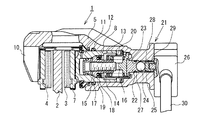
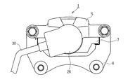
図1及び図2に示すように、本実施形態に係るディスクブレーキ1は、キャリパ浮動型液圧ディスクブレーキであって、車輪(図示せず)とともに回転するディスクロータ2(ディスク)の両側に配置された一対のブレーキパッド3,4(パッド)と、ディスクロータ2を跨ぐキャリパ5と、車両の非回転部分に固定されてブレーキパッド3,4及びキャリパ5を移動可能に支持するキャリア6とを備えている。
Hereinafter, an embodiment of the present invention will be described in detail with reference to the drawings.
As shown in FIGS. 1 and 2, the
キャリパ5には、一方のブレーキパッド3の裏金7に対向するシリンダ8が形成され、また、ディスクロータ2を跨いで他方のブレーキパッド4の裏金9に当接する爪部10が形成されている。シリンダ8には、有底円筒状のピストン11がフォールバックシール12を介して摺動可能に嵌装され、ピストン11の底部がブレーキパッド3の裏金7に当接している。シリンダ8及びピストン11の内部に、液圧室13が形成され、液圧室13の内部に、パッド摩耗調整機構14が設けられている。液圧室13には、油圧源であるマスタシリンダ(図示せず)が接続される。
In the
パッド摩耗調整機構14は、調整ナット15(クラッチ部材)及び調整ねじ16(プッシュロッド)を備えている。調整ナット15は、ピストン11内に回転可能に嵌合され、ピストン11に摩擦係合する摩擦面17を有しており、皿ばね18及びスラストワッシャ19によって、摩擦面17がピストン11に押圧されている。調整ねじ16は、一端部が調整ナット15に螺合し、他端部がシリンダ8に摺動可能に案内されて、その軸回りの回転が規制されており、コイルばね20によってシリンダ8の底部側へ付勢されて、駐車ブレーキ機構21(後述)の押圧ピストン22(プッシュロッド)に当接している。
The pad
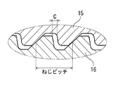
調整ナット15と調整ねじ16とは、多条ねじによって互いに螺合しており、回転及び直線運動の変換が相互に可能となっている。また、図3に示すように、調整ナット15及び調整ねじ16のねじ部には、所定の隙間C(バックラッシュ)が設けられており、相対回転することなく、隙間Cの分だけ相互に直線移動できるようになっている。調整ナット15は、調整ねじ16よりも液圧室に対する受圧面積が大きく、また、コイルばね20のばね力が皿ばね18のばね力よりも大きくなっている。
The
駐車ブレーキ機構21は、シリンダ8の底部に貫通された案内ボア23と、案内ボア23内に挿入された押圧ピストン22、鋼球24及びねじ部材25と、案内ボア23の外部に取付けられたモータユニット26(回転モータ、電動アクチュエータ、押圧機構)とを備えている。
The
押圧ピストン22は、案内ボア23に摺動可能かつ気密的に挿入されており、一端部が案内ボア23内の段部27に当接して、モータユニット26側への移動が規制され、他端部が調整ねじ16に当接している。ねじ部材25は、案内ボア23に形成されたねじ部28に螺合されて回転直動変換部材を構成しており、回転によって案内ボア23の軸方向に沿って進退動するようになっている。鋼球24は、押圧ピストン22とねじ部材25との間に介装され、ねじ部材25から押圧ピストン22へ回転力を伝達することなく、押圧力を伝達するようにしている。モータユニット26は、その回転軸29がねじ部材25に挿入されて摺動可能にスプライン結合されており、回転軸29によってねじ部材25を回転させて案内ボア23に沿って進退動させられるようになっている。図1中、符号30は、モータユニット26に通電するための導線を示す。
The
これにより、鋼球24、ねじ部材25、モータユニット25及びガイドボア23のねじ部28によって、シリンダ8の外部からピストン11の摺動方向に押圧力を発生する押圧機構が構成されている。
Thus, a pressing mechanism that generates a pressing force in the sliding direction of the
以上のように構成した本実施形態の作用について次に説明する。
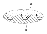
マスタシリンダから液圧室13へ液圧を供給すると、ピストン11がフォールバックシール12を撓ませながら前進して、一方のブレーキパッド3をディスクロータ2に押圧し、その反力によってキャリパ5を移動させ、爪部10を介して他方のブレーキパッド4をディスクロータ2に押圧する。これにより、ブレーキパッド3、4によってディスクロータ2を挟みつけて制動力を発生させる。マスタシリンダからの液圧を解除すると、フォールバックシール12の弾性によってピストン11が原位置まで後退して、制動が解除される。このとき、ブレーキパッド3,4の摩耗がない場合には、ピストン11は、調整ナット15と調整ねじ16とのねじ部の隙間C(図3参照)の範囲内で進退動するので、パッド摩耗調整機構14は作動しない。図4に、制動時の調整ナット15と調整ねじ16の位置を示す。
Next, the operation of the present embodiment configured as described above will be described.
When hydraulic pressure is supplied from the master cylinder to the
ブレーキパッド3、4が摩耗して、制動時にピストン11が隙間Cの範囲を超えて前進すると、ピストン11とフォールバックシール12との間に滑りが生じ、また、調整ナット15の摩擦面17とピストン11との摩擦係合が緩んで調整ナット15が回転して、パッド摩耗調整機構14が伸長してピストン11及び押圧ピストン22と当接した状態を維持する。なお、制動時に液圧室13に大きな液圧が作用して、爪部10の撓み等によって、ピストン11がねじ部の隙間Cを超えて変位した場合は、調整ナット15と調整ねじ16の受圧面積差及び皿ばね18とコイルばね20のばね力の差によって、調整ねじ15の摩擦面17がピストン11に押付けられて、これらの摩擦係合が維持され、調整ねじ15が回転しないことにより、パッド摩耗調整機構14の過調整を防止する。
When the
次に、駐車ブレーキ機構21の作動について説明する。
運転者が駐車ブレーキスイッチ(図示せず)等を操作し、液圧室13に液圧を供給して、ピストン11を前進させ、その後又は同時に、導線30によってモータユニット26に通電して、回転軸29を回転させ、これにより、ねじ部材25を回転させて前進させ、鋼球24、押圧ピストン22及びパッド摩耗調整機構14を介してピストン11を押圧して制動状態を維持する。その後、モータユニット26への通電を停止しても、ねじ部28との螺合によってねじ部材25の位置が保持されるので、制動状態を維持することができる。そして、モータユニット26の回転軸29を逆回転することにより、制動を解除することができる。このとき、パッド磨耗調整機構14は、上述のように、液圧による制動時に、ブレーキパッド3、4の摩耗に追従して伸長し、ピストン11及び押圧ピストン22との当接状態を維持することにより、ブレーキパッド3、4の摩耗を補償する。
Next, the operation of the
A driver operates a parking brake switch (not shown) and the like to supply hydraulic pressure to the
このとき、液圧室13へ供給する液圧は、例えば、運転者がフットブレーキを操作し、又は、アンチロックブレーキシステム、トラクションコントロールシステム、ビークルダイナミクスコントロールシステム等の油圧源を利用して発生させることができる。
At this time, the hydraulic pressure supplied to the
これにより、従来のコントロールケーブル(鋼製ワイヤ)が不要となり、代りに、屈曲性に優れた導線30を使用するので、車両への搭載性を向上させることができる。また、既存の駐車ブレーキ付ディスクブレーキ機構のパッド磨耗調整機構を利用できるので、信頼性が高く、製造コストもかからない。
Thereby, the conventional control cable (steel wire) becomes unnecessary, and since the conducting
なお、上記実施形態において、モータユニット26の回転軸29とねじ部材25とは、スプライン結合の代わりに、キー及びキー溝による結合構造としてもよい。鋼球24の代りに、スラストベアリングを使用することもできる。モータユニット26は、回転軸29を直接駆動してもよく、又は、減速機を介して駆動してもよい。また、モータユニット26及びねじ部材25の代りに、通電を停止しても作動位置を保持することができる自己保持型のソレノイドアクチュエータを用いて押圧ピストン22を直接押圧するようにすることもできる。
In the above embodiment, the rotating
1 ディスクブレーキ、2 ディスクロータ(ディスク)、3、4 ブレーキパッド(パッド)、8 シリンダ、11 ピストン、15 調整ナット(クラッチ部材)、16 調整ねじ(プッシュロッド)、24 鋼球(押圧機構)、25 ねじ部材(回転直動変換部材、押圧機構)、26 モータユニット(回転モータ、電動アクチュエータ、押圧機構)、28 ねじ部(回転直動変換部材、押圧機構)
1 disc brake, 2 disc rotor (disc), 3, 4 brake pad (pad), 8 cylinder, 11 piston, 15 adjustment nut (clutch member), 16 adjustment screw (push rod), 24 steel ball (pressing mechanism), 25 Screw members (rotation / linear motion conversion member, pressing mechanism), 26 Motor unit (rotation motor, electric actuator, pressing mechanism), 28 Screw portion (rotation / linear motion conversion member, pressing mechanism)
Claims (2)
前記押圧機構は、電動アクチュエータを有し、該電動アクチュエータが前記液圧源からの所定液圧供給と同時またはその後に駆動されることを特徴とするディスクブレーキ。 A pair of pads disposed on both sides of the disc, and a piston is slidably fitted to a bottomed cylindrical cylinder, and the piston is slid by a hydraulic pressure supply from a hydraulic pressure source. A caliper that makes the pad contact the disk, a pressing mechanism that is disposed outside the cylinder and generates a pressing force in the sliding direction of the piston, and a push rod that is disposed inside the cylinder and is moved by being pressed by the pressing mechanism; A disc brake including a clutch member disposed in the cylinder, screwed to one end side of the push rod and abutting on the piston, and pressed by the push rod to press the piston.
The disc brake according to claim 1, wherein the pressing mechanism includes an electric actuator, and the electric actuator is driven simultaneously with or after a predetermined hydraulic pressure is supplied from the hydraulic pressure source.
2. The disc brake according to claim 1, wherein the electric actuator is a rotary motor, and a rotary / linear motion converting member is interposed between the rotary motor and the push rod.
Priority Applications (1)
| Application Number | Priority Date | Filing Date | Title |
|---|---|---|---|
| JP2004106442A JP2005291337A (en) | 2004-03-31 | 2004-03-31 | Disc brake |
Applications Claiming Priority (1)
| Application Number | Priority Date | Filing Date | Title |
|---|---|---|---|
| JP2004106442A JP2005291337A (en) | 2004-03-31 | 2004-03-31 | Disc brake |
Publications (1)
| Publication Number | Publication Date |
|---|---|
| JP2005291337A true JP2005291337A (en) | 2005-10-20 |
Family
ID=35324500
Family Applications (1)
| Application Number | Title | Priority Date | Filing Date |
|---|---|---|---|
| JP2004106442A Pending JP2005291337A (en) | 2004-03-31 | 2004-03-31 | Disc brake |
Country Status (1)
| Country | Link |
|---|---|
| JP (1) | JP2005291337A (en) |
Cited By (9)
| Publication number | Priority date | Publication date | Assignee | Title |
|---|---|---|---|---|
| JP2007177996A (en) * | 2005-11-30 | 2007-07-12 | Hitachi Ltd | Disc brake with electric parking brake |
| CN103225658A (en) * | 2012-01-25 | 2013-07-31 | 株式会社万都 | Disc brake |
| JP2014020553A (en) * | 2012-07-20 | 2014-02-03 | Mando Corp | Caliper brake |
| JP2014020554A (en) * | 2012-07-20 | 2014-02-03 | Mando Corp | Caliper parking brake |
| KR101396866B1 (en) | 2008-02-18 | 2014-05-19 | 현대모비스 주식회사 | Caliper for parking brake in vehicles |
| CN104373489A (en) * | 2014-11-27 | 2015-02-25 | 京西重工(上海)有限公司 | Disc brake |
| JP2016125550A (en) * | 2014-12-26 | 2016-07-11 | 日立オートモティブシステムズ株式会社 | Disc brake |
| JP2017082834A (en) * | 2015-10-23 | 2017-05-18 | 株式会社アドヴィックス | Vehicle brake |
| CN112576660A (en) * | 2019-09-30 | 2021-03-30 | 廖志贤 | Device for making abrasion stroke by automatic compensation of hand brake |
-
2004
- 2004-03-31 JP JP2004106442A patent/JP2005291337A/en active Pending
Cited By (12)
| Publication number | Priority date | Publication date | Assignee | Title |
|---|---|---|---|---|
| JP2007177996A (en) * | 2005-11-30 | 2007-07-12 | Hitachi Ltd | Disc brake with electric parking brake |
| KR101396866B1 (en) | 2008-02-18 | 2014-05-19 | 현대모비스 주식회사 | Caliper for parking brake in vehicles |
| CN103225658A (en) * | 2012-01-25 | 2013-07-31 | 株式会社万都 | Disc brake |
| CN103225658B (en) * | 2012-01-25 | 2015-11-25 | 株式会社万都 | Disk type braker |
| JP2014020553A (en) * | 2012-07-20 | 2014-02-03 | Mando Corp | Caliper brake |
| JP2014020554A (en) * | 2012-07-20 | 2014-02-03 | Mando Corp | Caliper parking brake |
| CN104373489A (en) * | 2014-11-27 | 2015-02-25 | 京西重工(上海)有限公司 | Disc brake |
| US9587693B2 (en) | 2014-11-27 | 2017-03-07 | Bwi (Shanghai) Co. Ltd. | Disc brake |
| JP2016125550A (en) * | 2014-12-26 | 2016-07-11 | 日立オートモティブシステムズ株式会社 | Disc brake |
| JP2017082834A (en) * | 2015-10-23 | 2017-05-18 | 株式会社アドヴィックス | Vehicle brake |
| CN112576660A (en) * | 2019-09-30 | 2021-03-30 | 廖志贤 | Device for making abrasion stroke by automatic compensation of hand brake |
| CN112576660B (en) * | 2019-09-30 | 2022-08-02 | 廖志贤 | Device for making abrasion stroke by automatic compensation of hand brake |
Similar Documents
| Publication | Publication Date | Title |
|---|---|---|
| US8151948B2 (en) | Single motor electronic wedge brake system locking parking force | |
| EP1840405B1 (en) | Electric disk brake, caliper for the electric disk brake, motor/controller unit for the electric disk brake, and method for assembling the caliper for the electric disk brake | |
| KR101511437B1 (en) | Electro mechanical brake Apparatus | |
| JP5488909B2 (en) | Disc brake | |
| US12565184B2 (en) | Electromechanical brake and operating method thereof | |
| KR20160133098A (en) | Electric disk brake | |
| KR101271509B1 (en) | Electro Mechanical Brake | |
| JP2004225902A (en) | Disc brake with mechanical self-boosting | |
| JP5141911B2 (en) | Disc brake | |
| US6571921B2 (en) | Motor-driven disk brake | |
| CN107461428B (en) | Automobile brake-by-wire and control method | |
| JP2017502228A (en) | Actuator having irreversible screw nut system, drum brake, and brake device including the same | |
| JP5614528B2 (en) | Disc brake | |
| KR20220107460A (en) | Electro-mechanical brake | |
| KR20180060733A (en) | Ball Screw Type Electro-Mechanical Brake | |
| CN113494548A (en) | Friction braking system for vehicle | |
| JP2005291337A (en) | Disc brake | |
| JP2006177532A (en) | Disc brake | |
| JP2006283811A (en) | Disc brake | |
| WO2021157438A1 (en) | Disc brake | |
| KR100546238B1 (en) | Car electromechanical brake | |
| JPS61206834A (en) | Actuator for brake rigging | |
| JP2007100725A (en) | Disc brake | |
| JP2011075051A (en) | Disc brake | |
| JP2005291303A (en) | Disc brake |