US4921225A - Pneumatic spring structure with dual output force and pressure decay compensation and method of operation - Google Patents
Pneumatic spring structure with dual output force and pressure decay compensation and method of operation Download PDFInfo
- Publication number
- US4921225A US4921225A US07/353,553 US35355389A US4921225A US 4921225 A US4921225 A US 4921225A US 35355389 A US35355389 A US 35355389A US 4921225 A US4921225 A US 4921225A
- Authority
- US
- United States
- Prior art keywords
- cylinder
- shaft
- spring
- piston
- bushing
- Prior art date
- Legal status (The legal status is an assumption and is not a legal conclusion. Google has not performed a legal analysis and makes no representation as to the accuracy of the status listed.)
- Expired - Lifetime
Links
Images


Classifications
-
- F—MECHANICAL ENGINEERING; LIGHTING; HEATING; WEAPONS; BLASTING
- F16—ENGINEERING ELEMENTS AND UNITS; GENERAL MEASURES FOR PRODUCING AND MAINTAINING EFFECTIVE FUNCTIONING OF MACHINES OR INSTALLATIONS; THERMAL INSULATION IN GENERAL
- F16F—SPRINGS; SHOCK-ABSORBERS; MEANS FOR DAMPING VIBRATION
- F16F9/00—Springs, vibration-dampers, shock-absorbers, or similarly-constructed movement-dampers using a fluid or the equivalent as damping medium
- F16F9/32—Details
- F16F9/48—Arrangements for providing different damping effects at different parts of the stroke
- F16F9/49—Stops limiting fluid passage, e.g. hydraulic stops or elastomeric elements inside the cylinder which contribute to changes in fluid damping
-
- E—FIXED CONSTRUCTIONS
- E05—LOCKS; KEYS; WINDOW OR DOOR FITTINGS; SAFES
- E05F—DEVICES FOR MOVING WINGS INTO OPEN OR CLOSED POSITION; CHECKS FOR WINGS; WING FITTINGS NOT OTHERWISE PROVIDED FOR, CONCERNED WITH THE FUNCTIONING OF THE WING
- E05F1/00—Closers or openers for wings, not otherwise provided for in this subclass
- E05F1/08—Closers or openers for wings, not otherwise provided for in this subclass spring-actuated, e.g. for horizontally sliding wings
- E05F1/10—Closers or openers for wings, not otherwise provided for in this subclass spring-actuated, e.g. for horizontally sliding wings for swinging wings, e.g. counterbalance
- E05F1/12—Mechanisms in the shape of hinges or pivots, operated by springs
- E05F1/1292—Mechanisms in the shape of hinges or pivots, operated by springs with a gas spring
-
- F—MECHANICAL ENGINEERING; LIGHTING; HEATING; WEAPONS; BLASTING
- F16—ENGINEERING ELEMENTS AND UNITS; GENERAL MEASURES FOR PRODUCING AND MAINTAINING EFFECTIVE FUNCTIONING OF MACHINES OR INSTALLATIONS; THERMAL INSULATION IN GENERAL
- F16F—SPRINGS; SHOCK-ABSORBERS; MEANS FOR DAMPING VIBRATION
- F16F9/00—Springs, vibration-dampers, shock-absorbers, or similarly-constructed movement-dampers using a fluid or the equivalent as damping medium
- F16F9/06—Springs, vibration-dampers, shock-absorbers, or similarly-constructed movement-dampers using a fluid or the equivalent as damping medium using both gas and liquid
- F16F9/061—Mono-tubular units
-
- F—MECHANICAL ENGINEERING; LIGHTING; HEATING; WEAPONS; BLASTING
- F16—ENGINEERING ELEMENTS AND UNITS; GENERAL MEASURES FOR PRODUCING AND MAINTAINING EFFECTIVE FUNCTIONING OF MACHINES OR INSTALLATIONS; THERMAL INSULATION IN GENERAL
- F16F—SPRINGS; SHOCK-ABSORBERS; MEANS FOR DAMPING VIBRATION
- F16F9/00—Springs, vibration-dampers, shock-absorbers, or similarly-constructed movement-dampers using a fluid or the equivalent as damping medium
- F16F9/06—Springs, vibration-dampers, shock-absorbers, or similarly-constructed movement-dampers using a fluid or the equivalent as damping medium using both gas and liquid
- F16F9/066—Units characterised by the partition, baffle or like element
- F16F9/067—Partitions of the piston type, e.g. sliding pistons
-
- E—FIXED CONSTRUCTIONS
- E05—LOCKS; KEYS; WINDOW OR DOOR FITTINGS; SAFES
- E05Y—INDEXING SCHEME RELATING TO HINGES OR OTHER SUSPENSION DEVICES FOR DOORS, WINDOWS OR WINGS AND DEVICES FOR MOVING WINGS INTO OPEN OR CLOSED POSITION, CHECKS FOR WINGS AND WING FITTINGS NOT OTHERWISE PROVIDED FOR, CONCERNED WITH THE FUNCTIONING OF THE WING
- E05Y2900/00—Application of doors, windows, wings or fittings thereof
- E05Y2900/50—Application of doors, windows, wings or fittings thereof for vehicles
- E05Y2900/53—Application of doors, windows, wings or fittings thereof for vehicles characterised by the type of wing
- E05Y2900/548—Trunk lids
Definitions
- the gas spring units can extend, under gas pressure force acting on the effective piston shaft cross-section area, to move the lid to an open position.
- a control orifice by-pass in the gas spring effectively slows the opening speed of the lid.
- the pneumatic spring construction has been improved to provide a desired multi-output force feature as well as incorporating a unique method and structure to effectively decrease loss of operative gas pressure within the pneumatic spring resulting primarily from leakage of the gas directly through the shaft seal due to permeability of the material from which the seal is made.
- the latter aspect can be referred to as permeability compensation or pressure decay compensation.
- transverse springs with bellcrank linkage are seen in the following U.S. Patents: U.S. Pat. No. 3,724,797 to H. Freitag et al for Resilient Seat; U.S. Pat. No. 4,416,094 to F. Bugener et al for Attic Window Assembly; and U.S. Reissue Pat. No. Re. 26,162 to A. K. Simons et al for Vehicle Seat Rebound Control.
- An example of a different dual output force concept in a pneumatic spring can be seen in applicant's U.S. Pat. No. 4,451,964 (also No. 4,451,978) where a floating piston is utilized to provide the dual output force. While not teaching the pressure decay compensation invention of this application, U.S. Pat. No. 4,408,751 to Daniel P. Dodson and George C. Ludwig for Multi-chamber Temperature Compensated Pneumatic Counterbalance shows a fixed partition or wall module providing a separate gas chamber in a pneumatic counterbalance cylinder.
- a transversely mounted single pneumatic spring, bell crank and idler link assembly or apparatus will provide a compact installation for hinged closures such as automobile trunk lids or doors and other similar closures.
- the spring will float, being attached only to spaced-apart bellcranks.
- the forward space required for this counterbalance assembly is minimized being installed laterally just behind the rear seat and in the forward upper portion of the trunk. Only one spring unit is required, thus minimizing cost.
- the spring unit is effectively hidden or concealed at the front upper part of the trunk minimizing damage by items placed in the trunk.
- pneumatic spring enhancements such as the multi-output force feature of the present invention and the pressure decay compensation feature of the present invention can be incorporated in the spring unit to provide convenient operation of opening the lid and to improve the life expectancy of the pneumatic spring by minimizing and effectively negating pressure loss due to leakage of gas past the shaft seal.
- other features such as temperature compensation as taught in U.S. Pat. No. 4,408,751 can be easily added to the pneumatic spring inasmuch as the spring cylinder length can be made substantially longer than the piston shaft, the stroke of which is relatively short. Excess cylinder length provides the space or volume zones used for the various, above mentioned, enhancement features.
- the present invention has for a primary object the provision of a compact counterbalance apparatus for use with closure units where a single elongate pneumatic spring having shaft and cylinder end connector links are connected to arms of two spaced apart bellcranks, the other arms of which connect with idler links to a closure unit, secured for hinged movement to the frame structure of the closure, e.g., an automobile trunk lid with associated vehicle frame structure, the spring being supported laterally on the bellcranks so it floats in a plane parallel with the hinge axis of the closure lid.
- a single elongate pneumatic spring having shaft and cylinder end connector links are connected to arms of two spaced apart bellcranks, the other arms of which connect with idler links to a closure unit, secured for hinged movement to the frame structure of the closure, e.g., an automobile trunk lid with associated vehicle frame structure, the spring being supported laterally on the bellcranks so it floats in a plane parallel with the hinge axis of the closure lid.
- the disc valve can be fixed with a small axial floating movement to shift from an effective sealed relationship of its periphery with the cylinder wall to a free flow relationship so that orifice controlled flow is only in the direction of shaft extension under the high output force.
- the disc can be fixed in the cylinder wall to provide orifice controlled flow in both directions if so desired.
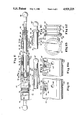
- FIG. 1 is a plan view of a counterbalance apparatus with a single transverse pneumatic spring link, bellcranks and associated links, mounted on automobile frame structure within the trunk of an automobile and attached to the lid of the trunk, a portion of the rear end of the automobile with trunk and trunk lid being illustrated by phantom lines with the lid in a closed condition and the spring link in a retracted, compressed condition;
- FIG. 2 is a view similar to FIG. 1 but with the trunk lid opened and the counterbalance spring link in its extended condition;
- FIGS. 3, 4 and 5 are detail perspective views looking toward the right hand side of the trunk in FIGS. 1 and 2, illustrating relative positions of elements of the counterbalance apparatus and one of the gooseneck hinge fittings for the trunk lid, FIG. 3 corresponding to the closed lid condition of FIG. 1, FIG. 5 corresponding to the full open lid condition of FIG. 2 and FIG. 4 showing a partially opened lid condition;
- FIG. 6 is an enlarged detail plan view of the right hand portion of FIGS. 1 with solid lines showing the FIG. 1 closed lid positions of the spring link, bellcranks, and the interconnecting links between the bellcrank and the lid hinge fitting and with phantom lines showing the FIG. 2 open lid positions of the same elements;
- FIG. 7 is an enlarged detail view corresponding to FIG. 5 but viewed from a higher angle to more clearly illustrate the position relationships of the counterbalance elements;
- FIG. 8 is a partially sectioned break-a-way plan view of a pneumatic spring link including dual force and pressure decay compensation elements which, if desired, can be used on a spring link for the counterbalance apparatus of FIGS. 1-7, phantom lines showing a full retracted condition where the dual force elements are operative;
- FIG. 9 is a detail view showing a second embodiment of the dual force operator sleeve unit.
- FIG. 10 is a detail view showing a third embodiment of the dual force sleeve unit where the operator sleeve is a short piece of cylindrical tubing slidable on the piston shaft;
- FIG. 11 is an enlarged detail view of the installed pressure decay compensator unit with its O-ring seal in sealed position, as shown in FIG. 8, and with a portion of the cylinder wall broken away;
- FIG. 11a is a modified embodiment of the pressure decay compensator depicted in FIG. 11;
- FIG. 12 is an enlarged side view of the pressure decay compensator element with its O-ring seal in a non-sealing position
- FIG. 13 is an end view looking at the left hand end of FIG. 12;
- FIG. 14 is a partially sectioned break-a-way plan view of a second embodiment of a dual force hydro-pneumatic spring link in extended condition
- FIG. 15 is a view similar to FIG. 14 but with the piston shaft partially retracted to a normal spring compressed condition
- FIG. 16 is a view of the spring of FIGS. 14 and 15 with the piston shaft in fully retracted condition where the dual force sleeve has been moved to relocate the bushing and shaft seal to increase the effective shaft cross-section area and then to decrease the cylinder gas volume and provide increased pressure on the gas;
- FIGS. 17a, b and c are three diagramatic section views showing a further embodiment of a multiple output force pneumatic spring link which provides a triple output force, FIG. 17a showing the shaft fully extended, FIG. 17b showing the shaft and one bushing part in the second output force position and FIG. 17c showing the shaft and both bushing parts in the third output force position;
- FIG. 18 is a further embodiment of the triple output force spring link of FIG. 17a, where a stepped collar on the shaft can be used in lieu of the stepped lengths of the two bushing parts;
- FIG. 19 is a diagramatic chart showing the general nature of a force vs. displacement slope curve for a dual output force spring link like that shown in FIG. 8;
- FIG. 20 is a second diagramatic chart showing the general nature of a force versus displacement slope curve for a triple output force spring link like that shown in FIG. 17.
- FIGS. 1 and 2 The invention combination herein described is generally shown in FIGS. 1 and 2 and includes a combination of elements which provide a compact counterbalance installation 30 for use with hinged closure lids, hatches or doors. It was developed for use with automobile trunk lids 32 and includes a single pneumatic spring 34 mounted transverse to and in the forward portion 36 of the trunk space under and parallel to the hinge axis 38 of the trunk lid.
- the invention incorporates an elongate pneumatic spring 34, with pivotal end fittings 40,42 connected to arms of two bellcranks 44 mounted at opposite sides of the trunk space and idler link connectors 46 from the other arms of the bellcranks to the trunk lid 32.
- the bellcranks are mounted on fixed pivot structure secured to the automobile frame.
- a convenient attachment for the idler links 46 is to goose neck shaped hinge members 48 rigidly secured to the opposite sides of the trunk lid 32 and hingedly mounted to brackets 50 rigid with the automobile body structure.
- the pneumatic spring floats and is attached only to associated arms of the bellcranks and is supported by the bellcranks which as noted are pivotally mounted on fixed pivot posts, journal studs, or the like 52.
- the output force of the pneumatic spring is equalized at both ends through the fixed pivot bellcranks 44 and in turn through the idler links 46 to the trunk lid 32 which in turn is constrained by its hinge members 48 to swing about its hinge axis 38 between a closed (FIG. 1) and open (FIG. 2) condition as a single, rather rigid, member.
- the forces exerted by the spring link can be varied by changing the kinematics of the connections between the spring link and the bellcrank arms and between the bellcrank arms and the connections to the lid or closure member.
- the spring link per se can be a conventional pneumatic spring, found commercially in many versions, but the pneumatic spring link 34 herein disclosed and described incorporates several improved features which can be used in combination or separately in many pneumatic spring installations, particularly in automotive use such as with the trunk lid disclosed herein.
- the spring link 34 (shown in more detail in FIG. 8), can incorporate a small assembly which, for convenience, will be termed a pressure decay compensator 60 (FIGS. 11, 12 and 13). It helps maintain the internal operative gas pressure in the spring link by replenishing the gas in the operative part of the spring cylinder 62 which over a period of time can leak through the material of the piston shaft seal 64 due to permeability of the seal material. Where installation space permits, an added length of the spring link cylinder is used as a fixed volume chamber 66 to store and maintain a quantity of gas under higher pressure than in the operative part of the spring link cylinder 62.
- the fixed volume chamber 66 is separated from the operative part of the cylinder by a sealed wall element, the pressure decay compensator 60, the seal 68 of which is made from a material with a similar or a different permeability characteristic as that of the shaft seal 64.
- the gas under higher pressure in the fixed volume chamber 66 will leak through or past the material of its wall seal 68 at a similar or differing rate, due in part to losses from dynamic cycle, and will replenish the lost gas from the operative part of the spring link 34.
- This feature will extend the useful life of a pneumatic spring link.
- the transverse arrangement of a spring link in an automobile trunk lid counterbalance installation provides more than enough room for an elongated cylinder to contain the fixed chamber, and will still enable the necessary length of stroke of the piston shaft 70 as may be needed for various installations.
- a second improved aspect of the herein disclosed spring link 34 is the incorporation of a cooperative assembly of elements enabling an effective multiple output force (e.g., dual, triple, etc.) for the spring link.
- Pneumatic springs are primarily based on the principle of pressure and volume. In retracted condition, when the piston shaft 70 is moved into the gas cylinder the volume is reduced and gas pressure increases. The piston shaft cross-section provides an area against which the gas pressure inside the cylinder working space creates a force tending to extend the piston shaft. When volume is decreased by a retraction movement of the shaft, the internal pressure is increased an amount proportional to the decrease in volume due to shaft stroke and cross-section.
- a counterbalance should essentially balance the weight of a trunk lid when it is first opened so the lid does not fly open in the face of a person when the trunk is unlatched, yet the spring force, usually due to kinematics of the connecting linkage must be sufficient to move and keep the lid in an open condition once the operator lifts it to an upper position.
- the use of the dual output force improvement in the transverse spring of the trunk counterbalance apparatus will provide an initially high output force during a small increment of spring link extension which will cause the trunk lid to pop open.
- This pop open force can be predetermined by predimensioning the amount of movement of the shaft seal at the fully retracted shaft condition so that the high pop-up force occurs for a distance causing the lid to open a convenient distance, e.g. two inches (or 50 mm.), and thereupon the spring link output force abruptly decreases to a point where the lid weight is greater than spring output force and the lid stays slightly open.
- the dual force slopes are illustrated in FIG. 19.
- phantom lines illustrate the rear part of an automobile.
- the floor of the trunk including the raised forward shelf or ledge part is part of the automobile body or frame structure and that forward ledge 36 (shown in phantom lines) serves as a convenient body support structure upon which to mount the two bellcranks 44.
- Both the right hand and left hand bellcranks 44 are identical but mounted in mirror image relationship with their mid fixed mounting pivot locations journalled on journal studs 52 so the bellcrank will be maintained against axial movement on the journal and can pivotally rotate about the Journal axes.
- Each journal stud can be secured in a known manner, e.g., by being screwed into or bolted to the ledge structure 36 with their axes transverse to the ledge and spaced apart on a line which is parallel to the hinge axis 38 of the trunk lid 32.
- Spacer sleeves 54 can be used with journal studs 52 to support the bellcranks above the surface of the ledge.
- each bellcrank 44 is made from flat sheet steel in a right triangular shape and its main pivot support is adjacent the ninety degree angle. Each side portion of the triangle constitutes an arm of the bellcrank.
- the bellcrank can be made in a conventional L-shape by stamping, forging or other metal forming operations. Adjacent each of the acute corner angles of and projecting up from the upper face of the bellcrank is a ball stud 55, 56 one of which 55 constitutes the connector for one end of the gas spring 34 and the other of which 56 provides a connector for the associated idler link 46.
- a socket 40 is shown, and can be rigidly secured by screw threads, welding or the like, to the end of the gas spring shaft 70 and is connected to the bellcrank stud 55 to provide a ball and socket swivel connection.
- the idler link 46 has its ends provided with socket formations 57 and 58 that respectively connect with associated ball studs 56 in the bellcrank and a ball stud 59 secured to project from the inner side of the lid goose neck hinge member 48 at a location spaced from the goose neck hinge axis 38 to provide a desired lever arm.
- sockets and ball studs are commercially available.
- socket connector 42 is interconnected to its associated ball stud in the other bellcrank.
- journal studs and eye connectors can be used as the spring link end connectors and all ball and socket connections can be made in well-known conventional manner to interconnect in a secure fashion and provide the necessary degree of universal swiveling, especially at the idler link connections.
- the portion A of bellcrank 44 located between the intermediate or middle journal stud 52 and the spring link connector stud 55 constitutes a first bell crank lever arm A which is connected to and transfers force to and from an associated end of the pneumatic spring 34.
- the portion B of the bellcranks located between the intermediate Journal stud 52 and the idler link ball stud 56 constitutes a second bell crank lever arm B which is connected to and transfers force to and from the associated idler link 46 and thence via its associated goose neck hinge member to and from the trunk lid 32.
- the trunk lid 32 is a substantially rigid member and in a conventional manner is firmly and rigidly secured to the goose neck hinge members 40 at each side of the front of the lid.
- the goose neck members are fastened to body frame brackets by heavy journal members 37 secured in the brackets as nut and bolt fittings or flat head journal pins, washers and clips or cotter pins.
- the hinged lid including the gooseneck hinge member is constrained to pivot about the hinge axis 38 as a rigid unit. Accordingly movement of the trunk lid between open and closed condition, where it is latched by a conventional latch mechanism to a keeper plate 33, is transmitted by equal angular movements of the two gooseneck members 48 via the idler links 46 to equal but opposite arcs of movement of the two bellcranks 44.
- the connected pneumatic spring 34 will be disposed on an axis between the bellcrank studs 55 which always remains parallel with the trunk hinge axis although it floats between a forward and a rearward position as the lid is moved between open and closed condition.
- the spring link 34 is in its compressed or retracted condition in which the first set of bellcrank arms A extend at a slight inclination, shown as about 20 degrees to the elongate spring link.
- the spring force is initially exerted via a short moment arm C (FIG. 6) to the bell crank 44 which biases the left and right bellcranks 44 as viewed in FIG. 1 with a clockwise force and counterclockwise force respectively.
- a short moment arm C (FIG. 6)
- the moment arm from bellcrank pivot 52 to the axis of idler link 46 varies slightly throughout the movement of trunk lid between closed and open positions, as shown in the representative kinematic layout, the moment arm remains essentially the length of lever arm B.
- the initial output force of spring link 34 is applied through a short moment arm via the bell crank to a longer moment arm thence via the idler link 46 and the goose neck hinge member to the trunk lid.
- the output force applied to the trunk lid is generally lower than the trunk lid load.
- the spring link 34 used in the transverse counterbalance apparatus 30 preferably has such an orifice bleed bypass construction.
- One such form of orifice bleed bypass is disclosed and described in conjunction with the pneumatic spring shown in detail in FIG. 8. That pneumatic spring embodiment includes the dual force output feature and the pressure decay compensation feature either or both of which can be included in the spring link 34 used in the transverse spring link counterbalance apparatus of FIGS. 1-7.
- the illustrated and described transverse spring link, bellcranks and idler link apparatus 30 represents one example of an installation for an automobile trunk lid. It will be understood by experienced engineers that the geometry and kinematics of the linkages can be varied to meet different installation requirements.
- the pneumatic spring stroke can be increased or decreased, the geometry of the bellcranks can be modified by changing the lengths of one or both arms and/or changing the angle between the arms.
- One example of changed geometry could be to increase the angle between the two arms of bellcrank 44 so the moment arm C of arm A passes slightly overcenter, past zero without permitting the other arm B to move past the bottom center location.
- FIG. 8 illustrates the components of counterbalance link 34 with a cylinder 62 whose length will be determined by the kind of equipment with which the unit is used.
- a piston assembly 80 which separates the cylinder into two operative compartments filled with gas (e.g., air, nitrogen or some other inert gas) under pressure.
- the piston assembly includes a free fitting piston 82, a piston washer 84, a piston ring 86, a piston ring washer 88, and the piston rod or shaft 70 secured at one end 90 to the piston assembly 80 as by swaging over or riveting the end at 92.
- These pneumatic counterbalance units particularly in automotive installations are often pressurized up to around 2000 psi gas pressure. Pressures can be higher or lower depending on the installation.
- a counterbalance unit with a piston rod having approximately 0.10 inch cross-section area will provide a 5 pound extension force when the cylinder is pre-pressurized at approximately 50 psi, and a 200 pound force when pressurized at 2000 psi.
- the piston shaft 70 projects out through one end 94 of cylinder 62, the other end of which is completely closed, as by welding an end plug or disc 96 thereto.
- the projected end of shaft 70 has a connector link 40 rigidly secured thereto, as by screw threads or welding, and a second connector link 42 is secured to the cylinder closed end unit 96, as by screw threads or welding.
- shaft 70 passes through a large bi-directional ring seal 64 (shown as a six lobe seal but which can be an O-ring or a Quad-seal), a Teflon washer 98, and a shaped bushing 72 which has a free fit around the shaft 70 and within cylinder 62.
- Suitable materials for the various components can be mandrel drawn hydraulic steel tubing for the cylinder, sheet steel for the end disc; the piston shaft is hardened, chrome plated steel; the bushing 72 is preferably made from half hard brass but can be made from other materials, such as aluminum or steel, the [Quad-ring] bi-directional shaft seal and O-ring seals are elastomeric, e.g., synthetic rubber or plastic, and the piston components 82 and 84 are made from sintered copper steel or they can be made from other materials, such as plastic, bronze, brass, aluminum, etc.
- the piston assembly and its piston ring components 86 and 88 are constructed to provide controlled by-pass flow of gas from one side of the piston to the other side. There is a relatively free flow by-pass provided during the retraction or compression stroke and an "orifice" metered flow of gas past the piston during the extension or expansion stroke.
- a similar piston construction is shown in U.S. Pat. No. 4,570,912.
- the washer part 84 of the piston assembly has a cylindrical periphery with an O.D. providing a close free sliding fit with the I.D. of cylinder 62. Because the washer 84 is rigidly secured on the shaft and a part of its periphery will always contact the cylinder wall because of a slight wobbling of the shaft during its reciprocation, the washer can provide an excellent electrically conductive path between the shaft and the cylinder.
- the inner bore of washer 84 fits over the reduced end 92 of the piston shaft, and in assembly the washer 84 and piston part 82, as a rigid spool-shaped unit, are clamped by swaging at 92 against the shoulder at the reduced end 90 of shaft 70.
- a rather large axially directed through passage 104 through the piston washer part 84 provides a free flow path through the washer 84. If desired, passage 104 could be an orifice passage.
- the other piston part 82 is cylindrical with a central through bore which slides over the piston shaft reduced end 90. Its side adjacent the washer 84 is shaped with a reduced diameter center boss 106 having a flat end face abutted against the washer 84.
- the outer circumference of piston part 82 has a lesser diameter than the I.D. of the cylinder so there is a free annular space enabling unobstructed flow of gas between piston part 82 and the cylinder wall.
- Piston part 107 radially outward from and between the central boss 106 and an outer peripheral, axially directed, flange 108, is axially recessed to provide free flow space from the center boss to the outer flange 108.
- Flange 108 has a narrow terminal annular edge which is disrupted by one or more very small shallow orifice grooves 110.
- the ring shaped flat washer 88 is loosely retained between the axial flange 108 of part 82 and piston O-ring 86, both of which can shift slightly in the groove between piston parts 82 and 84.
- washer 88 moves away from the piston flange 108 and permits unrestricted gas flow from the closed end of the cylinder, into the recess of piston part 82, through the aperture 104 of the piston washer 84, thence the other chamber of the counterbalance unit.
- the crimped end of cylinder 62 contains the end retainer bushing 72 and the bi-directional seal 64.
- the I.D. of the outer portion of bushing 72 is slightly larger than the shaft O.D. to avoid a close running fit which could create undesirable friction drag.
- the piston shaft will normally cant slightly and contacts the inside of the bushing 72 along a line contact which can aid in providing an electrical conductivity path if the link is used as an electrical connector.
- the Teflon washer 98 provides a resilient backing for the bi-directional seal 64 which provides a multiple circumferential line contact with both the shaft 70 and interior cylinder surface, in effect acting like plural small O-rings
- the six lobe seal 64 serves as an excellent bi-directional seal between the shaft and cylinder with relatively low friction forces against the shaft during expansion and contraction strokes.
- the cylinder should be pressurized with the gas prior to and while the seal around the shaft is inserted into the cylinder as is taught in the aforementioned U.S. Pat. No. 4,451,964.
- FIGS. 11, 12 and 13 show one construction of the pressure decay module 60 and its installation in a pneumatic spring cylinder as hereinbefore discussed.
- FIG. 11 is an enlarged detail of a part of the spring link 34 seen in FIG. 8.
- the module 60 is preferably made from metal, e.g., aluminum, brass or the like and as seen in FIG. 12 is essentially cylindrical with three annular peripheral flanges 114, 116, 118 dimensioned to provide a close free fit within cylinder 62. Flanges 114 and 116 enable the module 60 to be fixed at a desired location as by dimpled indents 120 in the wall of cylinder 62.
- the annular recess 122 between flanges 116 and 118 is divided into two annular areas of different diameters.
- Area 124 is a sealing surface, adjacent the middle flange 116, which transitions inward to a reduced annular diameter portion 126 adjacent the flange 118.
- the reduced diameter portion 126 provides an annular pocket which, when the O-ring 68 is disposed against flange 118, prevents the O-ring 68 from sealing against the reduced diameter portion 126, as shown in FIG. 12.
- a small hole 128 at the base of flange 118 provides a flow passage through the flange 118.
- the module unit 60 with the O-ring 68 assembled in recess 122 (FIG. 12) is inserted into the cylinder 62 to the desired location (FIG. 8) and retained in position by forming the dimples 120 in the cylinder wall.
- the cylinder preassembly is then subject to pressurization by applying gas under pressure through the shaft end of the cylinder. Such pressurization forces the O-ring 68 to a position against flange 118 which enables gas flow past the module flanges 114, 116 through the I.D. of O-ring 68 and thence through the passage 128 in flange 118 to load the fixed volume chamber 66 at the higher gas pressure desired to provide the pressure decay compensation aspect of this invention.
- FIG. 11a shows a slightly different construction of a pressure decay module 130 which is a solid metal disc with a stepped periphery forming an annular flange 132 on one side and a reduced diameter annular cylindrical sealing surface 134.
- a sealing O-ring 136 (corresponding to O-ring 68) is disposed in sealing engagement on the annular surface 134, against the surface of flange 132 and the internal surface of cylinder 62'.
- the diameter of flange 132 is dimensioned to provide a close free fit within cylinder 62'.
- the location of module 130, retained against axial movement toward the shaft end of the cylinder, is determined by its axial abutment against several dimpled indents 120' formed in the cylinder after insertion of the module 130 to the proper position.
- FIG. 11a is less expensive than that of FIG. 11, and provide a method for mechanical pressure check for correct pressure in fixed volume chamber 66' and containment of the gas under such pressure by the seal 136. Checking can be accomplished, before the spring assembly is completed, by applying a mechanical force against the module 130 in a direction toward the fixed volume chamber until the module is displaced away from the indents 120 and sensing the force required at the instant that displacement occurs.
- the pneumatic link 34 shown in FIG. 8 has structure which enables a dual output force to be obtained.
- the unit depicted in FIG. 8 includes a bushing 72, a Teflon washer 98 and a multilobe seal ring 64 which provides a bi-directional sealing engagement between the shaft 70 and the wall of cylinder 62.
- the bushing is maintained against the retaining means (e.g., crimped edge 100, in FIG. 8) at the open end of the cylinder by the high pressure of the gas contained in the cylinder or the bushing can be rigidly fixed at the open end of the cylinder.
- the retaining means e.g., crimped edge 100, in FIG. 8
- bushing 72 has an annular end abutment 140 which is accessible through an annular space 142 between the cylinder crimped end 100 and shaft 70 to the exterior of the gas spring.
- the bushing abutment 140 can be engaged by a cylindrical abutment member 144 placed on the end of shaft 70 between the end connection 40 and the cylinder.
- the abutment member 144 is a cylindrical cup rigidly secured on the end of shaft 70 by a screw fitting 146 portion of the end connector.
- the cup-shaped abutment member 144 is threaded onto the screw fitting 146 and fixed in position by lock nut 148.
- the end fitting with the secured abutment member 144 can be adjusted in length by screwing it into or out of the shaft 70.
- shaft 70 when moved in the retraction direction to an intermediate position, will cause the sleeve portion of abutment member 144 to coextensively engage the bushing abutment 140. Further movement of shaft 70 toward retraction, via the engaged abutments 144 and 140, causes the bushing 72 and seal 64 to translate with the shaft into the cylinder 62 up to a predetermined position which by design should avoid impingement of the seal 64 against the rolled indentation 102.
- the distance which the bushing can be inserted by the abutment 144 is determined by the location of bead 102, bearing in mind that the length of the sleeve of abutment 144 can be dimensioned to any desired length within the structural capabilities of a particular specific spring design.
- FIG. 9 shows a modified construction of the end fitting 40' with the same cup-shaped abutment 144.
- the end fitting 40' also screws into the shaft 70 but a shoulder on the end fitting abuts and clamps the cup-shaped abutment 40' rigidly against the end of shaft 70.
- FIG. 10 illustrates a further embodiment of the shaft mounted abutment which is a short cylindrical sleeve 146 mounted on shaft 70 for limited slidable movement.
- the end fitting 40" in this instance can be secured on the end of shaft 70 by any known manner, such as resistance welding or screwing to the end of the shaft.
- the end fitting 40" is made with a radial annular flange 148' which is greater in diameter than sleeve 146' and is used to abut sleeve 146' and force the sleeve into engagement with the bushing abutment 140'.
- Bushing translation and stepped second force output is essentially the same for structures of FIGS. 9 and 10 as described above for FIG. 8.
- the bushing 72 on its outer circumferential surface is provided with a plurality (3 are shown) of annular spaced apart grooves 150. These grooves are intended to contain and retain a corrosion preventative lubricant to inhibit deterioration of the cylinder's inside surface, specifically the portion of the cylinder which is translated by seal 64 whenever the bushing and seal are shifted as described.
- the bushing 72' besides having grooves 150', corresponding to grooves 150 of FIG. 8, incorporates an O-ring seal 152 in a retaining groove 154 to further aid in containing and retaining the corrosion preventative lubricant around the periphery of the bushing.
- an initial closing force is applied, manually or otherwise, on the lid, which force is transferred to the spring link.
- compression of the spring link shaft is initiated, i.e., starts to retract, as represented by point c.
- Further closure movement of the lid continues to compress (retract) the spring link which causes a displacement of the shaft into the cylinder a predetermined distance (224 mm. as shown on the chart) until the shaft abutment 144 engages the bushing abutment 140, represented by point d on the chart.
- the action is that representative of a conventional gas spring link, not having the abutment units which enable the subsequent second step in a dual output gas spring in accord with this invention.
- the principals of the dual output force spring link may be expanded to a spring link with any number of output steps, within reason.
- FIG. 17 (a, b and c) illustrate the multi-output force principal used in a gas spring which has a triple output force capability.
- Spring link 160 includes the cylinder 162, shaft 164 with its end connector and piston assembly 166 which are essentially the same as described for FIG. 8 and hence there is no need to describe these basic spring link components in further detail.
- the bushing is a two part telescoping bushing assembly 168 consisting of an outer cylindrical bushing 170 and an inner coaxial cylindrical bushing 172.
- the outer bushing 170 has a stepped outer end 174 which includes a reduced diameter projecting collar shaped abutment 176 with its O.D. dimensioned to freely translate through the opening in crimped end 178 of the cylinder 162.
- a bi-directional seal 182 e.g. a quad seal
- the inside of bushing 170 is made with a stepped cylindrical through bore 184, 186, which receives the inner bushing 172.
- the inside diameter of the portion 186 of the stepped bore is enough larger than the shaft diameter to permit a projected abutment collar 188 of the inner bushing to translate with a free close fit through the outer bushing and its abutment collar 176.
- Inner bushing 172 has its inside cylindrical passage 190 of constant diameter to provide a sliding fit on shaft 164.
- the outer circumference of bushing 172 is stepped to provide the projected collar 188 and a coextensive interior end portion 192 of larger outer diameter than the collar 188, which has a sliding fit within the bushing portion 184 of outer bushing 170.
- the exterior radial surface step 194 of inner bushing 172 will engage the interior radial surface step 196 of outer bushing 170 and determines the extended condition of the inner bushing 172 relative to the outer bushing.
- the extended condition of the outer bushing 170 is determined by abutment of its outer stepped end 174 against the crimped portion 178 of the cylinder.
- a bidirectional seal 198 is placed over the shaft 164 inside of bushing 170 and against the interior end of bushing 172.
- Seal 192 is shown as a double quad seal, but could be any suitable seal ring, e.g., cheveron, a square ring, O-ring or a multiple lobe seal. Gas under pressure is retained within the cylinder by the combination of the two telescoped bushings 170, 172 with their associated seals 182 and 198 and the crimped cylinder end 178.
- the gas pressure acting on the effective cross-section of the outer and inner bushings and their seal rings provides biasing forces on the bushings toward the bushing extended condition.
- the end connector 165 rigidly secured on shaft 164 provides an abutment surface 200 which can engage the ends of inner bushing collar 188 and outer bushing collar 176 in sequence as the spring link is compressed and the shaft is moved in retraction into the cylinder.
- FIG. 17a shows the shaft 164 fully extended and both of the telescoped bushings fully extended.
- FIG. 17b illustrates the shaft moved to an inward position where its end fitting abutment 200 has engaged the inner bushing collar 188 and pushed the inner bushing 172 to its fully inserted position relative to the outer bushing 170. This movement of inner bushing 172 together with the conjoint movement of shaft 164 causes the second stepped load increase.
- FIG. 17c illustrates the shaft being moved further inward from the position of 17b to a position where the end fitting abutment 200, still engaging the inner bushing collar 188, has also engaged the collar abutment 176 of the outer bushing 170 and has pushed the entire bushing assembly 168 and the shaft 164 to a complete fully inserted position relative to cylinder 162. This stage of movement of the entire bushing assembly together with the conjoint movement of the shaft causes the third stepped load increase.
- FIG. 18 shows an alternate embodiment wherein the telescoped bushing parts 170' and 172' have collar abutments 176' and 188' which terminate in the same radial plane when fully extended.
- the abutment structure enabling sequential insertion of the inner and outer bushings in this instance, is a stepped tubular collar 202 on shaft 164' which may be fixedly attached to end connector 165' or, as an integral unit, be allowed to slide freely on shaft 164'.
- the smaller diameter portion 204 of collar 202 is dimensioned to engage inner bushing collar 188' and the larger diameter portion 206 is dimensioned to engage outer bushing collar 176' and freely pass through the crimped end 178' of the cylinder.
- the coaction between the shaft abutment parts of collar 202 and the inner and outer bushings as the shaft is pushed from extended position to fully retracted position is the same as the stepped stages described in conjunction with FIG. 17.
- the length dimensions of the projected collar parts 176 and 188 of the bushings assembly 168 in FIG. 17 as well as the length dimensions of the stepped portions 204 and 206 of the stepped tubular collar 202 of FIG. 18 can be configured as required to obtain desired characteristic of the multiple output force spring link.
- FIG. 20 a second generalized exemplary force vs. displacement chart shown in FIG. 20 will be referred to.
- the values and curve depictions are merely exemplary, but are also derived from dynamic recordings of an actual spring.
- the spring link 160 When the spring link 160 is fully extended and in a free state under no load (FIG. 17a) the displacement is zero and output load is zero as indicated at 1 in FIG. 20.
- the spring link When the spring link is installed, e.g., to counterbalance an automobile hood, the spring link acts as a fixed link which maintains the hood in an open position represented by point m.
- an initial closing force is applied, manually or otherwise, on the hood, which force is transferred to the spring link.
- compression of the spring link shaft is initiated, i.e., starts to retract, as represented by point n.
- Further closure movement of the hood continues to compress (retract) the spring link which causes a displacement of the shaft into the cylinder a predetermined distance (144 mm. as shown on the chart) until the shaft abutment 200 engages the inside bushing abutment 188, represented by point o on the chart.
- the action is that representative of a conventional gas spring link, not having the abutment units which enable the subsequent second and third steps in a triple output gas spring in accord with this invention.
- the hood will not be fully closed, e.g., the hood position could be just before the conventional hood safety latch engages. Further movement of the hood past its conventional safety latch position to a position just prior to the fully closed hood latched position will cause the inner bushing 172 and its seal 198 together with shaft 164 as a unit to be inserted into the cylinder, requiring a higher force, e.g., 750 Newtons, to initiate (point p) the additional second stage of spring link displacement represented by the portion of the curve between points p and q. At point q the shaft abutment engages the abutments 188 and 176 of both the inner and outer telescoped bushings 172 and 170, as shown in FIG. 17b.
- pneumatic counterbalances There are many examples of uses for pneumatic counterbalances which can benefit from multiple output force characteristics of this invention and which could be in two, three, four or more stages.
- the following portion of this description represents use of a dual output force spring for a vehicle suspension.
- FIGS. 14, 15 and 16 illustrate a modified embodiment of the dual output force spring link illustrated and described in conjunction with FIG. 8.
- This example represents a spring link used as a vehicle suspension strut in which the cylinder and shaft are essentially in vertical disposition with the shaft end down. It supports the vehicle by a spring suspension and also provides dampening and shock absorbing of vehicle displacements and oscillations.
- the spring unit 220 consists of basic spring components, namely a closed end cylinder 222, a shaft 224 connected to a piston assembly 226, and end connectors 228 and 230.
- a special bushing 232 with projected collar 234, Teflon washer 236 and multilobe seal 238 are illustrated and serve the same purpose as described in conjunction with FIG. 8.
- a shaft associated abutment member 240 is a tubular sleeve slidable on the shaft 224 similar to the modification of FIG. 10.
- the aforementioned components of spring link 220 are essentially the same as shown in FIG. 8.
- FIGS. 14-16 of the original drawing are essentially full scale views with a cylinder length of approximately 8 inches in length (200 mm.).
- Spring link 220 contains a predetermined quantity of hydraulic fluid 242 (lubricating oil) and gas 244 under a predetermined pressure. Shown in a fully extended position in FIG. 14, the piston assembly abuts a rolled indentation 221 which provides the extended shaft limit position.
- the oil level must be such that the piston assembly 226, which can be made with or without the controlled flow structure and characteristics of the piston assembly 80, shown in FIG. 8, remains completely submerged in oil throughout its stroke from extended position to at least an intermediate position where the shaft abutment 240 engages the bushing collar 234.
- the piston assembly no longer has a dampening function because there is no longer a flow of fluid across the piston.
- the output force is effectively an undamped gas spring force due to compression and expansion of the volume of gas 244.
- Note the value of pressure of the preloaded gas under pressure will be determined by the output force required for a specific vehicle. Light weight vehicles may require 100 psi and heavier vehicles may require 2000 psi for the heavier loads.
- the amount of oil included in the spring link, over and above the requisite amount described above for dampening, can be varied to change the gas volume space and achieve desired load/displacement characteristics for specific installations.
- a supplemental dampening valve 250 may be incorporated in the cylinder 222 between the fully retracted position of the piston assembly 226 and the closed end of the cylinder. It consists of a disc shaped plate 252 mounted within the cylinder by indentations in the cylinder wall on each side of the disc. The O.D. of the disc is dimensioned to provide a close free fit within the cylinder.
- a rolled indentation 254 is provided in the cylinder wall at the side of the disc 252 facing the piston assembly and a plurality of circumferentially spaced-apart dimple indentations 256 are provided in the cylinder wall at the side of the disc facing the closed cylinder end.
- the axial spacing of the indentations 254 and 256 enables a slight axial movement of the disc 250 as a result of differential pressure across the disc caused by fluid flow during spring actuation.
- the locations of the rolled and dimpled indentations could be reversed which would reverse the respective directions of orifice controlled fluid flow and free fluid flow past the disc.
- the disc could be rigidly axially fixed in the cylinder between two rolled indentations wherein the path between the disc periphery and the cylinder will be effectively sealed in both directions.
- the periphery 260 of disc 252 is beveled to provide a conical seat against the rolled indentation 254, which results in a more positive sealing engagement.
- FIG. 15 shows the oil level coincident with the disc 252 at the time of contact between shaft abutment 240 and bushing extension 234. Further second stage displacement forces the higher viscosity incompressible hydraulic fluid (oil 242) past the disc in the free flow direction to the oil level shown in the fully compressed spring condition of FIG. 16.
- Extension force and velocity of the extending spring shaft is controlled by the flow of oil through the orifice 258 in the valve disc 252, and prevents an undamped high velocity shaft extension during the second stage which would occur due to the higher second stage pressures and forces.
- a multiple load path for the multiple output capability of the spring link can be accomplished by providing independent mechanical linkage connecting or abutting the bushing abutment, apart from the shaft abutment parts which are used in FIGS. 8 and 17.
- the multiple part telescoped bushing embodiment offers numerous capabilities, e.g., a universal construction can be mass-produced for economic efficiency and then during specific uses, all bushing parts can be pushed in simultaneously, providing a dual stage spring; only the inner bushing part can be pushed in and provides a dual stage spring with a reduced output force of the second stage; or the shaft abutment can be eliminated completely to provide a conventional normal output spring.
- a universal construction can be mass-produced for economic efficiency and then during specific uses, all bushing parts can be pushed in simultaneously, providing a dual stage spring; only the inner bushing part can be pushed in and provides a dual stage spring with a reduced output force of the second stage; or the shaft abutment can be eliminated completely to provide a conventional normal output spring.
Abstract
Description
Claims (11)
Priority Applications (1)
| Application Number | Priority Date | Filing Date | Title |
|---|---|---|---|
| US07/353,553 US4921225A (en) | 1986-12-19 | 1989-05-18 | Pneumatic spring structure with dual output force and pressure decay compensation and method of operation |
Applications Claiming Priority (3)
| Application Number | Priority Date | Filing Date | Title |
|---|---|---|---|
| US06/946,203 US4788747A (en) | 1986-12-19 | 1986-12-19 | Counterbalance apparatus with transverse pneumatic spring and bellcrank linkage |
| US07/246,682 US4854554A (en) | 1986-12-19 | 1988-09-20 | Pneumatic spring structure with dual output force and pressure decay compensation and method of operation |
| US07/353,553 US4921225A (en) | 1986-12-19 | 1989-05-18 | Pneumatic spring structure with dual output force and pressure decay compensation and method of operation |
Related Parent Applications (1)
| Application Number | Title | Priority Date | Filing Date |
|---|---|---|---|
| US07/246,682 Division US4854554A (en) | 1986-12-19 | 1988-09-20 | Pneumatic spring structure with dual output force and pressure decay compensation and method of operation |
Publications (1)
| Publication Number | Publication Date |
|---|---|
| US4921225A true US4921225A (en) | 1990-05-01 |
Family
ID=27399957
Family Applications (1)
| Application Number | Title | Priority Date | Filing Date |
|---|---|---|---|
| US07/353,553 Expired - Lifetime US4921225A (en) | 1986-12-19 | 1989-05-18 | Pneumatic spring structure with dual output force and pressure decay compensation and method of operation |
Country Status (1)
| Country | Link |
|---|---|
| US (1) | US4921225A (en) |
Cited By (17)
| Publication number | Priority date | Publication date | Assignee | Title |
|---|---|---|---|---|
| US5207530A (en) * | 1992-07-29 | 1993-05-04 | Halliburton Company | Underground compressed natural gas storage and service system |
| WO1998014725A1 (en) * | 1996-10-04 | 1998-04-09 | Avm, Inc. | Improved seal for gas springs and the like |
| US5895053A (en) * | 1996-10-04 | 1999-04-20 | Avm, Inc. | Seal for gas springs and the like |
| WO2000050787A1 (en) * | 1999-02-25 | 2000-08-31 | Avm, Inc. | High pressure multi-lobe seal |
| WO2000060177A2 (en) * | 1999-04-06 | 2000-10-12 | Downer Edwin E Jr | Energy conservation system for earth-moving loading machines |
| US20030209884A1 (en) * | 2002-05-13 | 2003-11-13 | Baxter International Inc. | Adaptable blood processing platforms |
| US6698729B2 (en) | 2001-06-15 | 2004-03-02 | Mark A. Popjoy | Gas spring having a controllable output force |
| US20050099060A1 (en) * | 2003-11-11 | 2005-05-12 | Hyundai Mobis Co., Ltd. | Torsion beam axle suspension |
| US20080163751A1 (en) * | 2007-01-09 | 2008-07-10 | Vijay Subramanian | Coated piston and coating method |
| US20080284073A1 (en) * | 2007-05-16 | 2008-11-20 | Heleski Clare P | Variable speed gas spring |
| US20090236105A1 (en) * | 2008-03-18 | 2009-09-24 | Duane Olson | Trip mechanism for a ground working tool |
| US20110067965A1 (en) * | 2009-09-18 | 2011-03-24 | Specialized Bicycle Components, Inc. | Bicycle shock absorber with slidable inertia mass |
| US20150000199A1 (en) * | 2012-01-12 | 2015-01-01 | Stabilus Gmbh | Drive Device |
| US20160169316A1 (en) * | 2013-09-13 | 2016-06-16 | Kyb Corporation | Mono-tube type hydraulic shock absorber |
| US9517673B2 (en) * | 2014-07-18 | 2016-12-13 | GM Global Technology Operations LLC | Vehicle and a suspension system for the vehicle |
| US20170044814A1 (en) * | 2015-08-12 | 2017-02-16 | Magna Closures Inc. | Electromechanical strut with lateral support feature |
| US10370226B2 (en) * | 2015-06-12 | 2019-08-06 | Manitowoc Crane Companies, Llc | Fast acting compressible stop |
Citations (8)
| Publication number | Priority date | Publication date | Assignee | Title |
|---|---|---|---|---|
| GB296897A (en) * | 1927-09-17 | 1928-09-13 | Noel Banner Newton | Improvements in or relating to shock absorbers |
| US1888578A (en) * | 1927-03-30 | 1932-11-22 | Cleveland Pneumatic Tool Co | Shock absorbing strut for aeroplanes |
| DE1057403B (en) * | 1954-01-23 | 1959-05-14 | Marie Lucien Louis B Christian | End cover for cylinders, especially of hydraulic shock absorbers, with tight piston rod feedthrough |
| US3056598A (en) * | 1958-04-18 | 1962-10-02 | Short Brothers & Harland Ltd | Under-carriage shock absorbers for aircraft |
| GB2015121A (en) * | 1978-02-22 | 1979-09-05 | Armstrong Patents Co Ltd | Filling Gas Springs |
| US4268018A (en) * | 1977-08-06 | 1981-05-19 | Stabilus Gmbh | Electrically conductive, telescoping spring |
| US4291788A (en) * | 1977-04-19 | 1981-09-29 | Tokico Ltd. | Cylinder head |
| US4570912A (en) * | 1982-10-08 | 1986-02-18 | Avm, Inc. | Pneumatic spring counterbalance having improved damping structure |
-
1989
- 1989-05-18 US US07/353,553 patent/US4921225A/en not_active Expired - Lifetime
Patent Citations (8)
| Publication number | Priority date | Publication date | Assignee | Title |
|---|---|---|---|---|
| US1888578A (en) * | 1927-03-30 | 1932-11-22 | Cleveland Pneumatic Tool Co | Shock absorbing strut for aeroplanes |
| GB296897A (en) * | 1927-09-17 | 1928-09-13 | Noel Banner Newton | Improvements in or relating to shock absorbers |
| DE1057403B (en) * | 1954-01-23 | 1959-05-14 | Marie Lucien Louis B Christian | End cover for cylinders, especially of hydraulic shock absorbers, with tight piston rod feedthrough |
| US3056598A (en) * | 1958-04-18 | 1962-10-02 | Short Brothers & Harland Ltd | Under-carriage shock absorbers for aircraft |
| US4291788A (en) * | 1977-04-19 | 1981-09-29 | Tokico Ltd. | Cylinder head |
| US4268018A (en) * | 1977-08-06 | 1981-05-19 | Stabilus Gmbh | Electrically conductive, telescoping spring |
| GB2015121A (en) * | 1978-02-22 | 1979-09-05 | Armstrong Patents Co Ltd | Filling Gas Springs |
| US4570912A (en) * | 1982-10-08 | 1986-02-18 | Avm, Inc. | Pneumatic spring counterbalance having improved damping structure |
Cited By (33)
| Publication number | Priority date | Publication date | Assignee | Title |
|---|---|---|---|---|
| US5207530A (en) * | 1992-07-29 | 1993-05-04 | Halliburton Company | Underground compressed natural gas storage and service system |
| US6179297B1 (en) * | 1996-10-04 | 2001-01-30 | Avm, Inc. | Seal |
| GB2333332A (en) * | 1996-10-04 | 1999-07-21 | Avm Inc | Improved seal for gas springs and the like |
| US5921557A (en) * | 1996-10-04 | 1999-07-13 | Avm, Inc. | Seal for gas springs and the like |
| US5921556A (en) * | 1996-10-04 | 1999-07-13 | Avm, Inc. | Seal for gas springs and the like |
| GB2333332B (en) * | 1996-10-04 | 2001-02-14 | Avm Inc | Improved seal for gas springs and the like |
| US5895053A (en) * | 1996-10-04 | 1999-04-20 | Avm, Inc. | Seal for gas springs and the like |
| WO1998014725A1 (en) * | 1996-10-04 | 1998-04-09 | Avm, Inc. | Improved seal for gas springs and the like |
| WO2000050787A1 (en) * | 1999-02-25 | 2000-08-31 | Avm, Inc. | High pressure multi-lobe seal |
| WO2000060177A2 (en) * | 1999-04-06 | 2000-10-12 | Downer Edwin E Jr | Energy conservation system for earth-moving loading machines |
| WO2000060177A3 (en) * | 1999-04-06 | 2001-02-22 | Edwin E Downer Jr | Energy conservation system for earth-moving loading machines |
| US6497059B1 (en) | 1999-04-06 | 2002-12-24 | Edwin E. Downer, Jr. | Energy conservation system for earth-moving loading machines |
| US6698729B2 (en) | 2001-06-15 | 2004-03-02 | Mark A. Popjoy | Gas spring having a controllable output force |
| US20030209884A1 (en) * | 2002-05-13 | 2003-11-13 | Baxter International Inc. | Adaptable blood processing platforms |
| US7032910B2 (en) * | 2002-05-13 | 2006-04-25 | Baxter International Inc. | Adaptable blood processing platforms |
| US20050099060A1 (en) * | 2003-11-11 | 2005-05-12 | Hyundai Mobis Co., Ltd. | Torsion beam axle suspension |
| US7427113B2 (en) * | 2003-11-11 | 2008-09-23 | Hyundai Mobis Co., Ltd. | Ball and socket mount for shock absorber of torsion beam axle suspension |
| US20080163751A1 (en) * | 2007-01-09 | 2008-07-10 | Vijay Subramanian | Coated piston and coating method |
| US20080284073A1 (en) * | 2007-05-16 | 2008-11-20 | Heleski Clare P | Variable speed gas spring |
| US20090236105A1 (en) * | 2008-03-18 | 2009-09-24 | Duane Olson | Trip mechanism for a ground working tool |
| US7823651B2 (en) | 2008-03-18 | 2010-11-02 | Cnh Canada, Ltd. | Trip mechanism for a ground working tool |
| US20110067965A1 (en) * | 2009-09-18 | 2011-03-24 | Specialized Bicycle Components, Inc. | Bicycle shock absorber with slidable inertia mass |
| US8960389B2 (en) * | 2009-09-18 | 2015-02-24 | Specialized Bicycle Components, Inc. | Bicycle shock absorber with slidable inertia mass |
| US9605735B2 (en) * | 2012-01-12 | 2017-03-28 | Stabilis Gmbh | Drive device |
| US20150000199A1 (en) * | 2012-01-12 | 2015-01-01 | Stabilus Gmbh | Drive Device |
| US20160169316A1 (en) * | 2013-09-13 | 2016-06-16 | Kyb Corporation | Mono-tube type hydraulic shock absorber |
| US9771999B2 (en) * | 2013-09-13 | 2017-09-26 | Kyb Corporation | Mono-tube type hydraulic shock absorber |
| US9517673B2 (en) * | 2014-07-18 | 2016-12-13 | GM Global Technology Operations LLC | Vehicle and a suspension system for the vehicle |
| US10370226B2 (en) * | 2015-06-12 | 2019-08-06 | Manitowoc Crane Companies, Llc | Fast acting compressible stop |
| US10625994B2 (en) | 2015-06-12 | 2020-04-21 | Manitowoc Crane Companies, Llc | Fast acting compressible stop |
| US20170044814A1 (en) * | 2015-08-12 | 2017-02-16 | Magna Closures Inc. | Electromechanical strut with lateral support feature |
| CN106437392A (en) * | 2015-08-12 | 2017-02-22 | 麦格纳覆盖件有限公司 | Electromechanical strut with lateral support feature |
| US10100568B2 (en) * | 2015-08-12 | 2018-10-16 | Magna Closures Inc. | Electromechanical strut with lateral support feature |
Similar Documents
| Publication | Publication Date | Title |
|---|---|---|
| US4854554A (en) | Pneumatic spring structure with dual output force and pressure decay compensation and method of operation | |
| US4921225A (en) | Pneumatic spring structure with dual output force and pressure decay compensation and method of operation | |
| US4788747A (en) | Counterbalance apparatus with transverse pneumatic spring and bellcrank linkage | |
| US4408751A (en) | Multi-chamber temperature compensated pneumatic counterbalance | |
| DE69725094T2 (en) | Device for regulating the vehicle height | |
| US4921223A (en) | Car suspension system | |
| US4483043A (en) | Automatic door closer | |
| US5628496A (en) | Pneumatic spring | |
| DE2414457C2 (en) | Gas spring with end cushioning | |
| US6959921B2 (en) | Temperature responsive valve assembly for a pneumatic spring | |
| US4530425A (en) | Shock absorber | |
| US4570912A (en) | Pneumatic spring counterbalance having improved damping structure | |
| US5127634A (en) | Hydropneumatic vehicle suspension strut | |
| US2087451A (en) | Shock absorber | |
| US5722643A (en) | Temperature compensated safety gas spring | |
| US4887515A (en) | Hydraulic cylinder apparatus | |
| US3147671A (en) | Hydraulic actuator | |
| US3143757A (en) | Hydraulic door closer | |
| GB2070192A (en) | Gas springs | |
| US3948498A (en) | Fluid filled spring damper including flexible end wall | |
| DE19944183A1 (en) | Hydraulic shock absorbers for motor vehicles | |
| US6520493B2 (en) | Lift support strut with directional damping | |
| US20080284073A1 (en) | Variable speed gas spring | |
| US3963225A (en) | Telescopic gas springs | |
| US10578182B2 (en) | Combination gas spring and damper |
Legal Events
| Date | Code | Title | Description |
|---|---|---|---|
| STCF | Information on status: patent grant |
Free format text: PATENTED CASE |
|
| FEPP | Fee payment procedure |
Free format text: PAYOR NUMBER ASSIGNED (ORIGINAL EVENT CODE: ASPN); ENTITY STATUS OF PATENT OWNER: SMALL ENTITY |
|
| FPAY | Fee payment |
Year of fee payment: 4 |
|
| FEPP | Fee payment procedure |
Free format text: PAT HOLDER CLAIMS SMALL ENTITY STATUS - SMALL BUSINESS (ORIGINAL EVENT CODE: SM02); ENTITY STATUS OF PATENT OWNER: SMALL ENTITY |
|
| REFU | Refund |
Free format text: REFUND OF EXCESS PAYMENTS PROCESSED (ORIGINAL EVENT CODE: R169); ENTITY STATUS OF PATENT OWNER: SMALL ENTITY |
|
| AS | Assignment |
Owner name: AVM, INC., SOUTH CAROLINA Free format text: ASSIGNMENT OF ASSIGNORS INTEREST;ASSIGNOR:MAREMONT CORPORATION;REEL/FRAME:006801/0314 Effective date: 19931115 |
|
| FPAY | Fee payment |
Year of fee payment: 8 |
|
| FPAY | Fee payment |
Year of fee payment: 12 |
|
| REMI | Maintenance fee reminder mailed | ||
| AS | Assignment |
Owner name: AVM INDUSTRIES, LLC, OHIO Free format text: ASSIGNMENT OF ASSIGNORS INTEREST;ASSIGNORS:AVM , INC.;AVM, INC.;REEL/FRAME:018171/0766 Effective date: 20060725 |
|
| AS | Assignment |
Owner name: PNC BANK, NATIONAL ASSOCIATION, PENNSYLVANIA Free format text: SECURITY AGREEMENT;ASSIGNOR:AVM INDUSTRIES, LLC;REEL/FRAME:018224/0236 Effective date: 20060725 |
|
| AS | Assignment |
Owner name: PNC BANK, NATIONAL ASSOCIATION, OHIO Free format text: SECURITY AGREEMENT;ASSIGNOR:AVM INDUSTRIES, LLC;REEL/FRAME:020385/0300 Effective date: 20071231 |
|
| AS | Assignment |
Owner name: AVM INDUSTRIES , LLC, SOUTH CAROLINA Free format text: RELEASE BY SECURED PARTY;ASSIGNOR:PNC BANK, NATIONAL ASSOCIATION;REEL/FRAME:031506/0018 Effective date: 20130917 |