EP4069382B1 - Benetzungskugel - Google Patents
Benetzungskugel Download PDFInfo
- Publication number
- EP4069382B1 EP4069382B1 EP20812353.9A EP20812353A EP4069382B1 EP 4069382 B1 EP4069382 B1 EP 4069382B1 EP 20812353 A EP20812353 A EP 20812353A EP 4069382 B1 EP4069382 B1 EP 4069382B1
- Authority
- EP
- European Patent Office
- Prior art keywords
- ball
- shell
- porous structure
- perforations
- liquid
- Prior art date
- Legal status (The legal status is an assumption and is not a legal conclusion. Google has not performed a legal analysis and makes no representation as to the accuracy of the status listed.)
- Active
Links
Images


Classifications
-
- A—HUMAN NECESSITIES
- A63—SPORTS; GAMES; AMUSEMENTS
- A63B—APPARATUS FOR PHYSICAL TRAINING, GYMNASTICS, SWIMMING, CLIMBING, OR FENCING; BALL GAMES; TRAINING EQUIPMENT
- A63B69/00—Training appliances or apparatus for special sports
- A63B69/0024—Training appliances or apparatus for special sports for hockey
-
- A—HUMAN NECESSITIES
- A63—SPORTS; GAMES; AMUSEMENTS
- A63B—APPARATUS FOR PHYSICAL TRAINING, GYMNASTICS, SWIMMING, CLIMBING, OR FENCING; BALL GAMES; TRAINING EQUIPMENT
- A63B43/00—Balls with special arrangements
- A63B43/002—Balls with special arrangements with special configuration, e.g. non-spherical
-
- A—HUMAN NECESSITIES
- A63—SPORTS; GAMES; AMUSEMENTS
- A63B—APPARATUS FOR PHYSICAL TRAINING, GYMNASTICS, SWIMMING, CLIMBING, OR FENCING; BALL GAMES; TRAINING EQUIPMENT
- A63B37/00—Solid balls; Rigid hollow balls; Marbles
- A63B37/02—Special cores
-
- A—HUMAN NECESSITIES
- A63—SPORTS; GAMES; AMUSEMENTS
- A63B—APPARATUS FOR PHYSICAL TRAINING, GYMNASTICS, SWIMMING, CLIMBING, OR FENCING; BALL GAMES; TRAINING EQUIPMENT
- A63B37/00—Solid balls; Rigid hollow balls; Marbles
- A63B37/12—Special coverings, i.e. outer layer material
-
- A—HUMAN NECESSITIES
- A63—SPORTS; GAMES; AMUSEMENTS
- A63B—APPARATUS FOR PHYSICAL TRAINING, GYMNASTICS, SWIMMING, CLIMBING, OR FENCING; BALL GAMES; TRAINING EQUIPMENT
- A63B37/00—Solid balls; Rigid hollow balls; Marbles
- A63B37/14—Special surfaces
-
- A—HUMAN NECESSITIES
- A63—SPORTS; GAMES; AMUSEMENTS
- A63B—APPARATUS FOR PHYSICAL TRAINING, GYMNASTICS, SWIMMING, CLIMBING, OR FENCING; BALL GAMES; TRAINING EQUIPMENT
- A63B43/00—Balls with special arrangements
-
- A—HUMAN NECESSITIES
- A63—SPORTS; GAMES; AMUSEMENTS
- A63B—APPARATUS FOR PHYSICAL TRAINING, GYMNASTICS, SWIMMING, CLIMBING, OR FENCING; BALL GAMES; TRAINING EQUIPMENT
- A63B2102/00—Application of clubs, bats, rackets or the like to the sporting activity ; particular sports involving the use of balls and clubs, bats, rackets, or the like
- A63B2102/22—Field hockey
-
- A—HUMAN NECESSITIES
- A63—SPORTS; GAMES; AMUSEMENTS
- A63B—APPARATUS FOR PHYSICAL TRAINING, GYMNASTICS, SWIMMING, CLIMBING, OR FENCING; BALL GAMES; TRAINING EQUIPMENT
- A63B2225/00—Miscellaneous features of sport apparatus, devices or equipment
- A63B2225/60—Apparatus used in water
Definitions
- the invention relates to the field of balls suitable of wetting a surface. More specifically the invention relates to sport balls suitable of wetting a surface during play, such as for instance hockey balls.
- US patent application 2006/0251830 describes an artificial grass system comprising an additional liquid release layer underneath the artificial blades of grass and a capillary channel extending from within said liquid release layer to said main surface.
- the capillary channels upon losing liquid, will fill themselves again with liquid from the release layer and carry this to the main surface, allowing the liquid to be continuously fed from underneath the main surface.
- a disadvantage of this artificial grass system is that it requires at least a part of the existing grass systems to be replaced. Moreover, such system is still using large water amounts and is prone to substantial installation costs.
- the present invention relates to a ball comprising a core and a porous structure encompassing the core.
- the core comprises a substantially impermeable outer surface.
- the porous structure is delimited by an outer surface and an inner surface.
- the inner surface of the porous structure coincides with the outer surface of the core.
- the outer surface of the porous structure comprises a plurality of perforations.
- the porous structure further comprises a plurality of hollow confined spaces. At least a part of the plurality of the porous structure perforations and at least a part of the plurality of hollow confined spaces are interconnected thereby defining a plurality of first liquid passages.
- the ball further comprises a shell encompassing the porous structure.
- the shell is delimited by a shell outer surface and a shell inner surface.
- the shell inner surface is the same as or coincides with the outer surface of the porous structure.
- a perforated foil is provided between the shell inner surface and the outer surface of the porous structure.
- the shell comprises a plurality of shell perforations. At least a part of the plurality of shell perforations extend between a shell outer opening in the shell outer surface and a shell inner opening in the shell inner surface. The at least part of the plurality of shell perforations are interconnected with the perforations of the porous structure thereby defining a plurality of second liquid passages.
- the first and second liquid passages thereby define liquid passages between the shell perforations and the hollow confined spaces and allow a liquid to be absorbed by the hollow confined spaces upon contact of the ball with the liquid.
- contact of the ball with the liquid may be performed by immersing the ball in a liquid or by sprinkling the ball with the liquid or in any other way considered suitable by the person skilled in the art.
- the ball further comprises control means for controlling absorption of liquid by the ball, for instance upon immersion of the ball in the liquid during a predetermined time period, e.g. to control the absorption rate of liquid by the ball and/or the amount of absorbed liquid by the ball upon contact, e.g.
- control means are structural control means, i.e. adaptations of structural features of the ball within certain ranges or additions of structural features as will be explained further in specific examples of embodiments of the present invention.
- the interconnections between the shell perforations and the hollow confined spaces can be regulated by structural variations of the ball, i.e. for instance the size, number, geometry of the shell perforations and/or shell channels, the size, number and geometry of the porous structure perforations and/or porous structure channels and/or the connection between shell perforations and porous structure perforations, the ball as such being adapted in such a way that the absorption and release of liquid by the ball is controlled and/or that the absorbed liquid is temporally stored in the hollow confined spaces in the absence of forces exerted on the ball (e.g. when the ball is at rest).
- the ball is adapted in such a way that at least a part of the absorbed liquid is released from the ball upon exertion of minimum external forces on the ball (the minimum external forces to be exerted on the ball may be chosen depending on the application the ball is used for), e.g. upon dropping the ball from a predetermined height and/or upon hitting the ball during playing with the ball, e.g. upon hitting the ball with a hockey stick during hockey play with a predetermined force.
- minimum external forces to be exerted on the ball may be chosen depending on the application the ball is used for
- the porous structure comprises a foam structure.
- the porosity of the foam structure may be adapted to control the absorption of liquid by the ball, for instance upon immersion of the ball in the liquid during a predetermined time period, e.g. to control the absorption rate of liquid by the ball and/or the amount of absorbed liquid by the ball upon contact, e.g. upon immersion, of the ball with the liquid during a predetermined time period.
- the porosity of the foam structure may be adapted to control the desorption of absorbed liquid by the ball, i.e. to control the conditions upon which absorbed liquid may be released again, e.g.
- the porosity of the foam structure may be adapted in any way considered suitable by the person skilled in the art, for instance by adapting the porosity of the foam structure, by varying the porosity with varying distance to the core, e.g. by decreasing or increasing the porosity with increasing distance from the core.
- the foam structure may comprise pores with a size between 1 ⁇ m and 2 mm, preferably between 1 ⁇ m and 1 mm.
- the plurality of perforations at the outer surface of the porous structure extend in a plurality of channels extending at least partly through the porous structure.
- the plurality of channels extend from the outer surface of the porous structure to the outer surface of the core.
- the plurality of channels interconnect the plurality of perforations in the porous structure with the plurality of hollow confined spaces in the porous structure.
- the plurality of channels comprise an inlet opening interconnected to the porous structure perforations and one or more outlet openings interconnected to the hollow confined spaces, as such creating a liquid flow path between the perforations of the porous structure and the hollow confined spaces of the porous structure, e.g. the pores of the foam structure.
- the one or more outlet openings may be provided in the side surface of the channel and the inlet opening may be provided in the base surface of the channel.
- the channels are tubular structures comprising two base surfaces and a tubular side surface. In this case the inlet opening will typically be provided in the top base surface and the one or more outlet openings will typically be provided in the side surface and/or bottom surface of the tubular structure.
- the channels may be adapted to control the absorption of liquid by the ball and desorption of absorbed liquid by the ball, as such forming at least part of the structural control means.
- the channels may be adapted in any way considered suitable by the person skilled in the art, for instance, without being limited thereto, by adapting the size, e.g. the diameter and/or length, of the channels, by varying the size of the channel with varying distance to the core, e.g. by decreasing or increasing the size, e.g. the diameter, of the channel with increasing distance from the core, by varying the number and/or size of the outlet openings/holes (if any) in the channels, the holes providing an interconnection towards the confined hollow spaces.
- the perforations of the porous structure and/or the channels extending from the porous structure may have a maximal size/diameter between 0,3 mm and 1 mm. This size is defined perpendicular to the direction in which liquid enters the channel from outside the ball.
- the length of the channels i.e. the distance between the channel inlet opening and the channel outlet opening is preferably between 4 and 10 mm .
- the holes in the circumferential surface of the channels may have a size, e.g. a diameter, between 0,1 mm and 1 mm. Such ranges are in particular suitable for sport balls, e.g. hockey balls.
- the shell inner openings of the plurality of shell perforations are positioned in a specific pattern with respect to the perforations of the porous structure.
- the shell inner openings of the shell perforations and the perforations of the porous structure partially or completely align or overlap, as such providing an interconnection between both and providing a liquid passage from the shell perforations towards the hollow confined spaces.
- the shell perforations comprise shell channels extending between the shell outer opening and the shell inner opening.
- the shell outer opening comprises a dimple, which may extend further in a shell channel towards the shell inner opening.
- the dimple typically has a conical shape, narrowing from the outside towards the inside of the shell.
- the shell perforations and perforations of the porous structure form a liquid channel connecting the outside to the hollow confined spaces and allowing a liquid to be absorbed by the ball and stored at least temporarily in the hollow confined spaces.
- the plurality of shell perforations have a maximal size/diameter between 0.3 mm and 1 mm. Such range is in particular suitable for sport balls, e.g. hockey balls.
- At least part of the shell perforations comprise a channel, extending between the shell outer opening and shell inner opening, the channel having a diameter between 0,3 mm and 1 mm.
- Such channels may form part of the control means, controlling the absorption and release of water by the ball.
- This size of a channel or perforations may be defined in the direction perpendicular with respect to the entry of liquid from outside the ball.
- the plurality of shell perforations have a size varying with the distance to the core of the ball.
- the diameter of the shell perforations e.g. the diameter of the channels between the shell inner and outer opening, may increase from the outer surface of the porous structure towards the outer surface of the shell, allowing a better control of liquid uptake and release by the ball.
- the ball comprises a perforated foil between the shell and the porous structure.
- the perforated foil may create a perturbated liquid flow path between the shell perforations and the hollow confined spaces of the porous structure, and may as such form at least a part of the control means of the ball for controlling the absorption and release of the liquid by the ball.
- the perforated foil is loosely provided in a limited space between the shell and porous structure. Loosely providing a perforated foil means that the foil is not fixated but that the foil can be pushed back and forward when fluid is being absorbed or released thereby creating perturbations in the fluid flow path.
- the foil perforations do not (completely) align or overlap with the shell perforations so that the fluid passage from shell to the porous structure is delayed and/or controlled.
- the thickness of the perforated foil is preferably between 50 and 200 ⁇ m.
- the porous structure preferably comprises a foam structure.
- the ball according to the present invention is a sports ball, preferably a hockey ball.
- the hockey ball may be adapted for playing hockey on a surface whereby the control means of the ball are adapted for releasing at least a part of the absorbed liquid when hitting the ball with a predetermined force during play.
- the hockey ball can be used to wet a surface during play, avoiding or reducing the need to wet the surface in advance.
- the ball according to the invention is used to wet a surface, for instance to wet a surface during playing with the ball, for instance while playing hockey, for instance while hitting the ball with a hockey stick during play.
- Such use may comprise as a first step immersion of the ball in a liquid reservoir during a predetermined time period.
- the predetermined time period may be chosen such that a sufficient amount of liquid can be absorbed by the ball and stored in the hollow confined spaces of the ball.
- a second step at least a part of the absorbed liquid will be released again by hitting the ball during play with a predetermined force, for instance when hitting the ball with a hockey stick.
- liquid absorption can again be realized and the balls can be re-used again to wet a surface.
- the following parameters may determine the amount of liquid that can be absorbed by the ball and/or the time period within which the liquid can be absorbed by the ball and/or the predetermined force that is needed to release a part of the liquid again, and as such form part of the control means of the ball: the diameter of the core, the core filling degree, the number of perforations in the outer surface of the porous structure, the porosity of the porous structure and the distribution of porosities, the size and geometry of the channels in the porous structure, the number of holes in the circumferential surface of the channels of the porous structure, the size of the hollow confined spaces, the number of shell perforations, the size and geometry of the shell perforations, the shell thickness, flow perturbation by the presence of a perforated foil between the shell and the porous structure, the number of perforations in the perforated foil
- control means at least comprise shell channels provided between the shell outer and shell inner opening interconnecting the shell perforations and the porous structure perforations.
- control means at least comprise channels in the porous structure interconnecting the porous structure perforations and the hollow confined spaces.
- the ball according to the present invention and its use may reduce the need to wet the surface in advance. Instead the ball itself wets the surface during play by releasing a part of the absorbed liquid when hitting the ball.
- a ball is provided which is suitable of wetting a surface based on the temporally storage of a liquid in the ball after immersion of the ball in that liquid.
- a ball is provided which is able to wet an artificial grass field during play.
- a ball is provided which is able to wet a surface when minimum predetermined forces are exerted on the ball, e.g. upon hitting the ball during play.
- a ball which is able to absorb a liquid, temporarily store the liquid in the ball, and desorb the liquid.
- a ball is provided that allows to control the bouncing of the ball due to damping by liquid take-up.
- the core (2) of the ball (1) may have any shape considered suitable by the person skilled in the art.
- the core (2) has a similar shape as the shape of the overall ball (1).
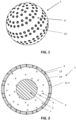
- the overall ball (1) has a spherical shape and the core (2) has therefore preferably a spherical shape, as shown in FIG. 2-9 .
- a spherical shape of the core (2) provides a better control over the rolling of the ball (1) on a surface.
- a spherical core (2) allows a better control over the center of gravity of the overall ball (1) provided that sufficient mass is present in this core (2).
- a spherical core (2) allows the center of gravity to coincide with the center of the overall ball (1), even when a liquid is being absorbed by the ball (1), and it allows a well-defined ball trajectory during play, when rolling over the surface as well as when passing above the surface.
- other shapes are possible like for instance elliptical or oval or any other random shape.
- the mass of the core (2) of the ball according to embodiments of the present invention may be determined taking into account the mass of the overall bal. For sports applications in particular a ball often needs to meet certain mass requirements, for instance fall with a certain mass range between a minimum and maximum mass.
- the mass of the core (2) of the ball (1) according to embodiments of the present invention may be determined taking into account such mass range and taking into account the possible mass increase due to absorption of liquid by the ball.
- An example of such liquid is water but the invention is not limited hereto and the liquid may be for example an oil or gel.
- the core of the ball according to embodiments of the present invention may have a mass between 20 % and 90 % of the total mass of an empty ball, i.e. a ball which has not yet absorbed any liquid. More preferably the core of the ball has a mass between 30 and 80 % of the total mass of an empty ball.
- the size of the core (2) is in general defined by the maximum distance between the edges of that core or the diameter of the core D core in case of a spherical core of the ball and according to embodiments of the present invention may be determined taking into account the size/diameter of the overall ball and/or the mass requirements of the overall ball and/or the material properties of the core.
- the outer surface of the core of the ball of the present invention is substantially impermeable such that only a maximum of 15 m% of the absorbed liquid is able to pass through the outer surface of the core and enter the core, preferably a maximum of 5 m% of the total amount of absorbed liquid is able to pass through the outer surface of the core.
- the outer surface of the core is impermeable, such that liquid absorbed by the overall ball is unable to pass through the outer surface of the core and thus enter the core.
- the inner part of the core (2) of the ball (1) of the present invention i.e. the part between the outer surface of the core (2) and its center, is preferably made of a substantially impermeable material, although the invention is not limited thereto and the core may also be made of a porous or non-porous material.
- the core (2) of the ball (1) may be made of a polymeric material, e.g. poly(lactic acid) (PLA) or acrylonitrile-butadiene-styrene copolymer (ABS) or blends containing different polymeric materials and/or polymeric materials with additional additives.
- a polymeric material e.g. poly(lactic acid) (PLA) or acrylonitrile-butadiene-styrene copolymer (ABS) or blends containing different polymeric materials and/or polymeric materials with additional additives.
- a core (2) of a ball (1) according to the present invention may have a spherical shape having a diameter D core in the range of 20 mm-65 mm, more specifically in the range of 30 mm-60 mm and/or a mass in the range of 15 g to 200 g more specifically in the range of 50 g to 180 g.
- the core may be made of ABS or any other material considered suitable by the person skilled in the art. Such a ball is particularly suited for playing hockey on an artificial turf field.
- the ball (1) comprises a porous structure (3) encompassing the core (2).
- the porous structure (3) is delimited by an outer surface (5) and an inner surface (6).
- the porous structure (3) comprises a plurality of perforations (7) in its outer surface (5) allowing a liquid to pass through, i.e. to enter the porous structure (3) from outside the ball (1) or to exit the porous structure (3) from inside the ball (1).
- the porous structure (3) further comprises a plurality of hollow confined spaces in which a liquid can be at least temporarily stored.
- At least a part of the plurality of perforations (7) and at least a part of the plurality of hollow confined spaces are interconnected, such that a liquid entering the ball (1) through the perforations (7) may be absorbed and at least temporarily stored in the hollow confined spaces.
- the porous structure is preferably adapted to limit absorption of such liquid upon immersion of the ball in a liquid.
- the porous structure is preferably adapted in such a way that the alternation of the total mass of the ball (1) upon immersion of the ball in a liquid for a predetermined time period is not excessive.
- the porous structure is preferably adapted in such a way that the alternation of the total mass of the ball upon immersion of the ball in a liquid for a predetermined time period, for instance during 30 minutes is at most 35%, more preferably at most 30%. Controlling the amount of liquid absorbed by the ball may also allow controlling the bouncing of the ball due to damping by liquid take-up.
- the part of interconnected perforations (7) and hollow spaces may be adapted to allow a liquid to be absorbed with a predetermined absorption rate upon contact of the ball (1) with the liquid, e.g. upon immersion of the ball (1) in the liquid, and to be at least partly released with a predetermined desorption rate.
- the part of interconnected perforations (7) and hollow spaces are therefore adapted to control the amount of absorbed liquid by the porous structure upon immersion of the ball in a liquid during a predetermined time period and/or for controlling release of the absorbed liquid from the porous structure, e.g. after a ball rebound test.
- the interconnected perforations (7) and hollow spaces are adapted to control absorption of liquid by the ball and release of absorbed liquid from the ball, for instance adapted in such a way that the absorbed liquid remains in the hollow confined spaces in the absence of forces exerted on the ball (1) (e.g. when the ball (1) is at rest) during a predetermined time period, for instance during 30 minutes.
- the part of interconnected perforations (7) and hollow spaces are adapted in such a way that the at least a part of the absorbed liquid is released from the ball (1) upon exertion of significant external forces on the ball (1), e.g. upon dropping the ball (1) from a certain height, e.g.
- the control means for controlling the absorption of liquid by the ball and release of absorbed liquid from the ball comprises channels interconnecting the porous structure perforations and the hollow confined spaces and the channels being adapted to perturbate the liquid flow between the porous structure perforations and the hollow confined spaces.
- the following parameters of the channels may be adapted to control such absorption and release: the diameter/size of the channel, the geometry, the length of the channel, and the number and size of fluid outlets in the channels.
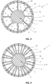
- the porous structure (3) comprises a foam structure (9) , as is for instance shown in FIG. 2-4 and FIG. 8-9 .
- the outer surface (5) of the porous structure (3) comprises a plurality of perforations (7) through which a liquid can pass, i.e. enter or exit, the porous structure (3).
- the plurality of perforations (7) may be formed by a plurality of outer pores in the outer surface (5) of the foam as is for instance shown in FIG. 2 and FIG. 3 .
- the plurality of perforations (7) may be complemented by a plurality of channels (10) extending through a part of the porous structure (3) and/or through a part of the foam structure as for instance shown in FIG. 4 .
- Such channels interconnect the plurality of porous structure perforations and the plurality of hollow confined spaces.
- the plurality of channels (10) may extend between the outer surface (5) of the porous structure (3) and an intermediate inner part of the porous structure (3) (not shown), i.e. an inner part of the porous structure (3) between the outer (5) and inner surface (6) of the porous structure (3), or may fully extend between the outer (5) and inner surface (6) of the porous structure (3) as shown in FIG. 4 .
- Such channels (10) may be adapted to control absorption of liquid by the ball and release of absorbed liquid from the ball, in particular the conditions upon which liquid can be absorbed by the ball and released again, as such forming part of the control means of the ball.
- the channels (10) may comprise one or more outlet openings, e.g. holes or ports, which are interconnected with the hollow confined spaces, such that liquid entering the porous structure (3) may pass through the holes of the channel towards the hollow confined spaces and such that liquid leaving the hollow confined spaces may pass through the holes of the channel towards the outside of the ball (1).
- outlet openings e.g. holes or ports
- the inner part of the foam structure i.e. the part of the foam structure between the inner and outer surface (5) of the foam structure, comprises a plurality of inner pores (11) which form a plurality of hollow confined spaces in which a liquid can be at least temporally stored.
- Preferably at least a part of the inner pores are interconnected forming larger confined spaces in which a liquid can be at least temporally stored.
- At least a part of the inner pores is connected with at least a part of the perforations (7) at the outer surface (5) of the porous structure, such that a liquid entering the porous structure (3) through the perforations (7) is able to enter the inner pores, be stored there, and exit the inner pores towards the perforations and eventually leave the ball (1).
- at least a part of the channels (10) in the porous structure are connected with at least a part of the inner pores of the foam structure.
- the foam structure (9) may be made of one piece as is for instance shown in FIG. 2 or may be made of several pieces as is for instance shown in FIG. 3 , leading to a multi-piece structure. In the latter case the different pieces may be at least partly interconnected as is shown in FIG. 4 . Alternatively, the different pieces are not interconnected and are separated from each other with non-permeable pieces (16) as shown in FIG. 3 .
- the interconnection between the different pieces of foam may be realized by a number of channels (10) in the porous structure comprising one or more openings at least partly overlapping with inner pores of the foam structure.
- An interconnection is preferred because a liquid entering the porous structure can be more homogeneously divided inside the ball (1). This has the advantage that the point of gravity remains substantially the same, which is in particular advantageous for sports balls. Also exit of liquid benefits from this advantage.
- the interconnection between the perforations (7) and the hollow confined spaces may be such that a liquid can pass more easily from the perforations (7) to the hollow confined spaces as vice versa, thereby realizing a faster absorption rate than release.
- the interconnection between the perforations (7) and the hollow confined spaces may be such that a liquid can pass from the perforations (7) to the hollow confined spaces upon immersion of the ball (1) within a liquid during a predetermined time period, while the liquid may only pass from the confined spaces to the perforations (7) during playing with the ball (1), for instance upon hitting the ball (1) during play.
- the porosity of the foam may be homogeneous, meaning that the porosity does not change throughout the structure, or heterogeneous, meaning that the porosity changes throughout the structure.
- the pore size is defined by the maximum distance between edges of a single pore.
- the porosity may vary with varying distance from the core (2), for instance increase with increasing distance from the core (2) or decrease with decreasing distance from the core (2), benefiting from a possible variation of the overall size of the foam structure. Varying the porosity may allow controlling the liquid uptake and release efficiency.
- the foam structure may be a closed cell foam or an open cell foam. For hockey ball (1) application, the pore size may vary from 1 ⁇ m to 2 mm.
- the interconnection between the perforations (7) and the hollow confined spaces may be such that the absorption and desorption of a liquid by the porous structure (3) is controlled. Controlling the absorption and desorption may be done in such a way that an absorption of the liquid by the ball (1) is faster than a desorption or vice versa. A faster absorption may allow a liquid to pass to the confined hollow spaces and be at least temporarily stored there.
- the interconnection between the perforations (7) and the hollow confined spaces may be such that a liquid can pass from the perforations (7) to the hollow confined spaces upon immersion of the ball (1) within a liquid during a predetermined time period, while the liquid may only significantly pass from the confined spaces to the perforations (7) during playing with the ball (1), for instance upon hitting the ball (1) during play.
- a ball (1) may allow wetting the active zone of a playground, for instance when playing hockey the zone where the ball (1) is present is sufficiently wet.
- the porosity of the foam structure may be changed with changing distance from the center of the ball (1), preferably with the larger pores in the region further away from the center of the ball (1).
- the channels in the porous structure and/or in the foam structure may be shaped to ease absorption of a liquid and slow down desorption.
- the channel geometry can be adapted. Considering for instance a tubular geometry this implies that instead of using a constant diameter for the channel the diameter of the channel may be changed with changing distance from the beginning to the end of the channel, with the beginning defined as the part of the channel closest to the center of the ball (1) thus the core.
- the diameter of the channel may for instance increase with increasing or decreasing distance from the core (2), the increase being continuous or in discrete steps.
- the porous structure (3) may be made of open cell polyurethane foam, woven fabrics or nonwovens (e.g. cotton) cork or hydrogels..
- the maximal thickness of foam structure is preferably between 5 and 50 mm.
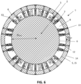
- the porous structure (3) comprises a plurality of hollow containers (8) as is for instance shown in FIG. 5 and FIG. 6 .
- the plurality of hollow containers form the plurality of hollow confined spaces, in which a liquid entering the ball (1) because of outer contact of the ball (1) with such liquid can be temporally stored and the as such stored liquid can exit the ball (1) at a later stage when predetermined conditions are met.
- the outer surface (5) of the porous structure (3) based on hollow containers (8) comprises a plurality of perforations (7) through which a liquid can enter or exit the porous structure (3) as is for instance shown in FIG. 10.
- the plurality of perforations may be formed by or extend in a plurality of channels extending through a part of the porous structure (3).
- the plurality of channels may extend between the outer surface (5) of the porous structure (3) and an intermediate inner part of this porous structure (3), i.e. an inner part of the porous structure (3) between the outer and inner surface (6) of the porous structure (3) or may fully extend between the outer and inner surface (6) of the porous structure (3).
- Such channels (10) may be adapted to control absorption of liquid by the ball and release of absorbed liquid from the ball, in particular the conditions upon which liquid can be absorbed by the ball and released again, as such forming part of the control means of the ball.
- the hollow containers (8) is connected with at least a part of the channels (10), such that a liquid entering the porous structure (3) through the channels is able to enter the hollow containers and be at least temporarily stored therein. Similarly such connection is relevant for exit of liquid.
- the plurality of hollow containers may be interconnected or not and be of various shapes (e.g. trapezoid prism) and volumes (e.g. 500 mm 3 ).
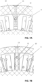
- the interconnection between different hollow containers may for instance comprise transversal connections, i.e. connections in a direction as shown in FIG. 7 . An interconnection between at least a part of the different containers is preferred as this may result in a more homogeneous distribution of the liquid inside the ball (1).
- the channels may comprise one or more outlet openings or holes (12) which are connected and/or overlap at least partly with one or more of the hollow containers as shown in FIG. 7 .
- These holes as located for instance on the circumferential surface of the channels, have a maximal size between 0.1 and 1 mm.
- any other connection between the channels and the hollow containers may be used allowing a liquid to pass from channels to hollow containers and back throughout the complete porous structure.
- the interconnection between the perforations (7) defining the outside of the porous structure and the hollow containers defining the inside of the porous structure may be such that the absorption and desorption of a liquid by the porous structure is controlled. Controlling the absorption and desorption may be done in such a way that absorption of the liquid by the ball (1) is faster than desorption or vice versa. A faster absorption may allow a liquid to pass to the confined hollow spaces and be at least temporarily stored there.
- the interconnection between the perforations (7) and the hollow confined spaces may be such that a liquid can pass from the perforations (7) to the hollow confined spaces upon immersion of the ball (1) within a liquid during a predetermined time period, while the liquid may only significantly pass from the confined spaces to the perforations (7) during playing with the ball (1), for instance upon hitting the ball (1) during play.
- a ball (1) may allow wetting the active zone of the playground, for instance when playing hockey, allowing the zone where the ball (1) is present to be sufficiently wet.
- the channel geometry can be adapted.
- the diameter of the channel in the porous structure may be changed with changing distance from the beginning to the end of the channel, with the beginning defined as the part of the channel closest to the center of the ball (1) thus the core (2).
- the diameter of the channel may for instance increase with increasing or decreasing distance from the core (2), the increase being continuous or in discrete steps.
- the ball (1) comprises a shell (4) covering a porous structure (3) as shown in FIG. 3-FIG. 9 .
- the shell (4) is delimited by an outer surface (14) in contact with the environment and an inner surface (15), the inner surface (15) may be in contact with the outer surface (5) of the porous structure.
- the outer surface of the shell comprises a plurality of shell perforations extending between a shell outer opening in the outer shell surface and a shell inner opening in the shell inner surface.
- the plurality of shell perforations (13) allows a liquid to enter the ball (1) and pass through the shell (4) of the ball (1) towards the porous structure. Also the reverse movement of liquid exit is possible.
- At least a part of the plurality of shell perforations (13) is interconnected with at least a part of the perforations of the porous structure (7), allowing a liquid to pass from the shell perforations through the porous structure perforations (7) to the hollow confined spaces and reversely.
- the shell (4) of the ball (1) may be made of a polymeric material, e.g. PLA or ABS or polyolefin (e.g. polyethylene or polypropylene) or blends containing different polymeric materials and/or polymeric materials with additional additives.
- a polymeric material e.g. PLA or ABS or polyolefin (e.g. polyethylene or polypropylene) or blends containing different polymeric materials and/or polymeric materials with additional additives.
- the shell perforations (13) may have any shape or geometry considered suitable by the person skilled in the art.
- the shell perforations (13) are shaped such that absorption and desorption of a liquid by the shell (4) is controlled.
- controlling the absorption and desorption of a liquid may be done in such a way that absorption of a liquid by the ball (1) is faster than desorption or vice versa.
- a faster absorption may allow a liquid to pass through the shell perforations to the confined hollow spaces and be at least temporarily stored there.
- the interconnection between the shell perforations (13) and the hollow confined spaces may be such that a liquid can pass from the shell perforations to the perforations of the porous structure to the hollow confined spaces upon immersion of the ball (1) within a liquid during a predetermined time period, while the liquid may only pass significantly from the confined spaces back to the shell (7) during playing with the ball (1), for instance upon hitting the ball (1) during play.
- a ball (1) may allow wetting of the active zone of a playground, for instance when playing hockey the zone where the ball (1) is present on the play surface is sufficiently wet.
- the diameter of the shell perforations may be changed with changing distance through the shell.
- the diameter of the shell perforations may for instance increase with increasing or decreasing distance from the porous structure (3) or the center of the ball (1). The increase may be continuous or in discrete steps.
- the shell perforations may be formed by a dimple, for instance in the case of sports ball (1).
- the shell perforations may be formed by a dimple followed by a shell channel with varying geometry interconnected to the dimple thereby allowing for a liquid passage through the shell (4).
- Such shell channels may be provided between the shell outer and shell inner opening interconnecting the shell perforations and the porous structure perforations.
- the shell channels may form part of the control means for controlling absorption of liquid by the ball and release of liquid from the ball.
- At least a part of the shell perforations are interconnected with at least a part of the perforations of the porous structure (3), allowing a liquid to pass from the shell (7) through the perforation of the porous structure (3) to the hollow confined spaces or reverse.
- the inner opening of the shell perforation may therefore be positioned in a specific pattern with respect to at least one of the perforations of the porous structure, preferentially in close vicinity or even overlapping with at least one of the perforations of the porous structure.
- any other connection considered suitable by a person skilled in the art is possible. A specific example is given in FIG.
- the shell thickness (D shell in FIG. 6 ) is preferably smaller than the thickness of the porous structure (3) and may be varied as considered suitable by the person skilled in the art.
- the shell thickness is preferably varied between 1 and 20 mm to allow for a sufficient material strength and to enable a variation of shell perforation channel lengths, thereby controlling the absorption and release of liquid by the ball. For hockey balls this size range is specifically suited.
- the number of shell perforations may be varied as considered suitable by the person skilled in the art. For hockey balls one can specifically have a number of shell perforations as high as the number of dimples.
- the liquid uptake and release is directly related to the number of shell perforations as it is respectively the first and last contact with the outer environment.
- the ball according to embodiments of the present invention comprises a perforated foil between the shell and the porous structure as shown in FIG 8 and FIG. 9 .
- the perforated foil can be adapted to perturbate the liquid flow from the shell towards the porous structure and vice versa, thereby providing part of the structural control means of the ball for controlling absorption and release of liquid by and from the ball.
- the perforated foil is not fixated to the shell nor to the inner porous structure but loosely fits in a narrow space between them.
- the foil can be pushed back and forward when fluid is being absorbed or released, thereby creating additional resistance for the liquid to enter or leave the porous structure.
- the foil perforations are not aligned or do not completely overlap with the shell perforations and perforations of the porous structure, again creating additional resistance for the liquid to enter or leave the porous structure and as such controlling the absorption and release of liquid by and from the ball.
- the thickness of the foil is preferably between 50 and 200 ⁇ m.
- the foil can be made of a polymeric material such as polyethylene
- the size of the foil perforations is preferably between 0.5 and 2 mm, preferably around 1 mm.
- the distance between the foil perforations is preferably between 1 and 4 cm.
- a ball (1) according to embodiments of the present invention may be a 3-layer ball as shown in FIG 2-7 , comprising a core (2), a porous structure (3) encompassing the core (2), and a shell (4) covering the porous structure (3).
- Such design parameters are, without being limited thereto, the following: (i) the diameter of the core; (ii) the core filling degree as defined as the m% of material present in the core (e.g. between 5 and 100%); (iii) the materials types used for the different layers of the ball (1); (iv) perforations in the outer surface (5) of the porous structure having a variable number and size; (v) the flexibility to have one piece or multi-pieces of foam as porous structure (3) with a certain inner pore size either homogeneously or heterogeneously distributed; (vi) a porous structure based on hollow containers comprising channels with variable number and geometry; (vii) the channels having a variable length and size (e.g.
- the diameter of the core of the ball (1) is preferably between 20 mm and 65 mm and/or the core filling degree is preferably between 5% and 100 % and/or the diameter of the porous structure channel preferably varying between 0,3 mm and 1 mm and/or the number of holes of the porous structure channels preferably varies between 1 and 3, and/or the diameter of the shell perforations is preferably between 0,2 and 0,6 mm and/or the shell thickness is preferably between 1 mm and 20 mm, the length of the shell perforations/shell channels is preferably between 1 mm and 20 mm, the perforated foil layer, if any, preferably has a thickness between 50 and 200 ⁇ m with a perforation diameter between 0.5 and 2 mm and a distance between the perforations in the range of 1 to 4 cm.
- control means of the ball are preferably adapted to allow a m% absorption between 10 and 35 m% upon immersion of the ball in a reservoir of liquid during 15 to 60 minutes, more preferably between 20 and 40 minutes.
- a m% absorption is defined as the mass increase of the ball as a result of absorption of liquid by the ball upon contact of the ball with the liquid during a predetermined time period (i.e. the mass of the absorbed liquid) compared to the mass of the dry ball, i.e. the mass of the ball without liquid.
- control means of the ball are preferably adapted to allow a m% release of liquid between 0.1 and 15 m% upon a regulated ball rebound test according to EN12235 (2013), more preferably between 1 and 10 m%.
- a m% release of liquid is defined as the mass of liquid leaving the ball, e.g. upon a regulated ball rebound test according to EN12235 (2013), compared to the mass of liquid absorbed by the ball upon contact of the ball with the liquid during a predetermined time period, e.g. upon immersion of the ball in the liquid during a predetermined time period.
- the balls according to embodiments of the present invention can be fabricated via different processing techniques. For example, 3D printing or additive manufacturing can be considered. Alternatively, injection and rotational molding can be considered or foam casting or extrusion. Also combinations of these processing techniques can be used. Several halves may be made and the connection can be facilitated by for instance gluing, friction welding or heating.
- Embodiments of a ball (1) according to the present invention will be described to illustrate certain advantages of the present invention. Such advantages are illustrated by the variation of design parameters, with for illustration purposes the focus on the variation of one such parameter to highlight the effect. The scope of the invention is however not limited to these embodiments.
- the multilayer balls with a porous structure based on hollow containers are obtained as one part by 3D printing in spherical shape, using commercially available configurations.
- the multilayer balls based on foams are for illustration purposes also 3D printed but in two halves that are connected to each other by a glue.
- the number of outer perforations is fixed at 242 in line with the number of dimples in a conventional thus currently used hockey ball.
- the filler degree of the core is also fixed at 40%.
- the overall diameter of the ball is 72 mm in each case.
- the performance of the exemplary balls is evaluated regarding both the capacity of liquid absorption and desorption, selecting for illustration purposes tap water as liquid.
- For the absorption of liquid focus is on the increase in mass after 30 minutes of immersion of a dry ball in a reservoir of liquid.
- the performance is evaluated based on the mass percentage of liquid absorption minimizing experimental error by reporting an average value based on a three time testing procedure.
- a m% absorption between 10 and 35 m% after immersion of the ball in a reservoir of liquid is preferred for hockey ball applications.
- focus is on the mass % loss (so with respect to the absorbed amount; again average value for a three time testing procedure) after a regulated ball rebound test.
- the vertical ball rebound is measured by releasing a ball from 2 meter height and measuring acoustically its rebound on a surface.
- the surface is a polyethylene 7000dtex carpet laid on a 15mm layer, i.e. a layer of styrene-butadiene rubber particles bounded by a polyurethane glue.
- the method used is the EN 12235 (2013).
- a m% loss between 0.1 and 15 m% preferably between 1 and 10 m% after a ball drop is preferred for hockey ball applications.
- the presented results are also discussed in view of these desired ranges for hockey ball applications but the main purpose is to illustrate the effect on the trends in absorption and desorption capacity, explaining why the reported m% values are not necessarily falling in these specific desired ranges for hockey ball applications.
- Balls 8-10 are 3-layer balls as shown in FIG. 6-7 .
- the mass of the empty balls 8-10, so without having the liquid absorbed, are respectively 108,6 g, 119,3 g and 112.9 g.
- the core has a spherical shape with a diameter of 50 mm.
- the shell has a thickness of 4 mm and porous structure a thickness of 7 mm.
- the tubular channels in the porous structure comprise 2 holes which are connected to neighboring hollow confined spaces of the porous structure.
- Balls 8-10 are 3D printed and are made of PLA.
- the porous structure and the shell comprise a number of straight channels having a constant size/diameter of 0.6 mm (ball number 8), 0.4 mm (ball number 9) and 0.2 mm (ball number 10).
- the size of the shell perforations are respectively 0.6 mm, 0.4 mm and 0.2 mm.
- Immersion of balls 8-10 in water for 30 minutes results in a mass increase of the ball due to absorption of water of respectively 21 %, 3% and 1%.
- a mass decrease of the ball due to release of liquid of respectively 39%, 73% and 85% is reported, highlighting the relevance of the diameter of the shell perforations
- Balls 18-19 are 3-layer balls and are shown based on the concept in FIG 6-7 .
- the mass of the dry or empty balls 18-19 are respectively 133.2 g and 135.9 g.
- the core has a spherical shape with a diameter of respectively 50 mm.
- the shell thicknesses are respectively 4 and 6 mm.
- the corresponding porous structures have a thickness of 7 and 5 mm.
- the tubular channels in the porous structure comprise 1 hole which are connected to neighboring hollow confined spaces of the porous structure.
- Balls 18-19 are 3D printed and are made of ABS.
- the porous structure and the shell comprise a number of channels.
- the shell channels have a variable diameter from 0.4 mm (toward center of ball) to 0.8 mm (toward outer part of ball) in a linear manner.
- the smallest diameter of the shell channel is also the diameter of the channel in the porous structure.
- Immersion of balls 18-19 in water for 30 minutes results in a mass increase of the ball due to absorption of water of respectively 27 and 20%, highlighting the relevance of the variation of the thickness of the shell.
- a mass decrease of the ball due to release of liquid of respectively 34% and 35% is reported.
- Balls 9, 11 and 12 are 3-layer balls and are based on the concept in FIG 6-7 .
- the mass of the balls 9, 11 and 12 are respectively 119,3 g, 115.5 g and 110.3 g.
- the core has a spherical shape with a diameter of 50 mm.
- the shell has a thickness of 4 mm and the porous structure a has a thickness of 7 mm.
- the tubular channels in the porous structure comprise 2 holes which are connected to neighboring hollow confined spaces of the porous structure.
- Balls 9, 11 and 12 are 3D printed and are made of PLA.
- the porous structure and the shell comprise a number of channels with variation in the tubular geometry within the shell.
- Ball 9 has a constant shell diameter of 0.4 mm (straight channel).
- Ball 11 has shell channels with a variable diameter from 0.4 mm (toward center of ball) to 0.8 mm (toward outer part of ball) in a linear manner.
- Ball 12 this is the reverse so from 0.8 to 0.4 nm.
- the smallest diameter of the shell channel is also the diameter of the channel in the porous structure.
- Balls 17 and 18 are 3-layer balls and are shown based on the concept in FIG 6-7 .
- the mass of the balls 17 and 18 are respectively 133.5 g and 133.2 g.
- the core has a spherical shape with a diameter of respectively 50 mm.
- the shell has a thickness of 4 mm and the thickness of the porous structure is 7 mm.
- the tubular channels in the porous structure comprise respectively 2 and 1 holes which are connected to neighboring hollow confined spaces of the porous structure.
- Balls 17 and 18 are 3D printed and are made of ABS.
- the shell comprises a number of channels having a variable diameter from 0.4 mm (toward center of ball) to 0.8 mm (toward outer part of ball) in a linear manner.
- the smallest diameter of the shell channel is also the diameter of the channel in the porous structure.
- Balls 13-14 are 3-layer balls and are shown based on the concept in FIG 6-7 .
- the mass of the balls 13-14 are respectively 133.2 g and 146.6 g.
- the core has a spherical shape with a diameter of respectively 50 and 60 mm.
- the shell has a thickness of 4 mm so that the corresponding thicknesses of the porous structure are 7 and 2 mm.
- the channels in the porous structure comprise 2 holes which are connected to neighboring hollow confined spaces of the porous structure.
- Balls 13-14 are 3D printed and are made of ABS.
- the porous structure and the shell comprise a number of straight channels having a diameter of 0.6 mm. Immersion of balls 13-14 in water for 30 minutes results in a mass increase of the ball due to absorption of water of respectively 23 and 9%. A mass decrease of the ball due to release of liquid of respectively 26% and 15% is reported, highlighting the relevance of the diameter of the core.
- Ball 8 is a 3-layer ball based on the concept in FIG 6-7 .
- the mass of the ball 8 is 108,6 g.
- the core has a spherical shape with a diameter of 50 mm.
- the shell has a thickness of 4 mm and the porous structure has a thickness of 7 mm.
- the tubular channels in the porous structure comprise 2 holes which are connected to neighboring hollow confined spaces of the porous structure.
- Ball 8 is 3D printed and is made of PLA.
- the porous structure and the shell comprise a number of channels with variation in the tubular geometry within the shell.
- Ball 8 has a constant shell diameter of 0.6 mm (straight channel).
- Ball 21 is a 3-layer ball based on the concept in FIG 2 with a single piece polyurethane foam with homogenously distributed pores with an average size between 1 ⁇ m and 0.1 mm and the same core as ball 8. Also the shell is the same as for ball 8 so that the size of the porous structure is also the same
- the mass of ball 21 is 122 g. Immersion of balls 8 and 21 in water for 30 minutes results in a mass increase of the ball due to absorption of water of respectively 21 and 22%. A mass decrease of the ball due to release of liquid of respectively 39% and 4% is reported, highlighting the relevance of the porous structure type.
- Ball 37 is a 3-layer ball based on the concept in FIG. 2 with a single piece polyurethane foam with homogenously distributed pores with an average size between 1 ⁇ m and 0.1 mm.
- the core has a spherical shape with a diameter of 50 mm.
- the shell has a thickness of 4 mm and the porous structure has a thickness of 7 mm.
- Ball 37 is 3D printed and is made of ABS.
- the shell comprises a number of straight channels having a constant size/diameter of 0.6 mm.
- Ball 38 is the extended version of ball 37 having an additional polyethylene foil of thickness 60 ⁇ m with perforations of 1 mm diameter at a 1 cm distance (so 4 per cm 2 ) provided between the shell and polyurethane foam, as shown in FIG 8 .
- the foil perforations are not aligned with the perforations in the shell, i.e. they do not overlap.
- Immersion of balls 37 and 38 in water for 30 minutes results in a mass increase of the ball due to absorption of water of respectively 21 and 22%.
- a mass decrease of the ball due to release of liquid of respectively 39% and 4% is reported, highlighting the relevance of the film layer with a controlled perforation pattern to control the liquid passage.
- Ball 43 is a 3-layer ball based on the concept in FIG. 8 with a polyurethane foam as 1 piece porous structure with homogenously distributed pores with an average size between 1 ⁇ m and 0.1 mm.
- the core has a spherical shape with a diameter of 50 mm.
- the shell has a thickness of 4 mm and the porous structure has a thickness of 7 mm.
- Ball 43 is 3D printed and is made of ABS.
- the shell comprises a number of straight channels having a constant size/diameter of 2 mm. It also has a polyethylene perforated foil of thickness 60 ⁇ m with perforations of 1 mm diameter that are at 1 cm distance (so 4 per cm 2 ). The foil perforations are not aligned with the perforations in the shell.
- Ball 44 is comparable to ball 43 but the diameter of the foil perforations is 5 mm. Immersion of balls 43 and 44 in water for 30 minutes results in a mass increase of the all due to absorption of water of respectively 47 and 46%. A mass decrease of the ball due to release of liquid of respectively 7% and 11% is reported, highlighting the relevance of the foil/film with a controlled perforation pattern to control the liquid passage.
- Ball 38 is a 3-layer ball with a polyurethane foam as a single piece porous structure with homogenously distributed pores with an average size between 1 ⁇ m and 0.1 mm.
- the core has a spherical shape with a diameter of 50 mm.
- the shell has a thickness of 4 mm and the porous structure has a thickness of 7 mm.
- Ball 38 is 3D printed and is made of ABS.
- the shell comprises a number of straight channels having a constant size/diameter of 0.6 mm. It also contains a polyethylene foil/film layer of thickness 60 ⁇ m with perforations of 1 mm diameter that are at 1 cm distance (so 4 per cm 2 ) consistent with FIG. 8 .
- Ball 48 is comparable to ball 38but the foam is a 3D woven nylon structure with a higher maximum pore size of 1 mm. Immersion of balls 38 and 48 in water for 30 minutes results in a mass increase of the ball due to absorption of water of respectively 21 and 22%. A mass decrease of the ball due to release of liquid of respectively 39% and 4% is reported, highlighting the relevance of the foam type.
- Number Mass dry ball (g) Mass after 30 min immersion (g) Liquid absorption (m%) Mass after ball drops (g) liquid desorption (m%) 38 119.6 174.9 46 169.7 9 48 112.9 146.9 30 144.3 8
Landscapes
- Health & Medical Sciences (AREA)
- General Health & Medical Sciences (AREA)
- Physical Education & Sports Medicine (AREA)
- Manufacture Of Porous Articles, And Recovery And Treatment Of Waste Products (AREA)
- Non-Silver Salt Photosensitive Materials And Non-Silver Salt Photography (AREA)
- Manufacturing Of Micro-Capsules (AREA)
- Electrochromic Elements, Electrophoresis, Or Variable Reflection Or Absorption Elements (AREA)
Claims (15)
- Ball (1), umfassend einen Kern (2), der Kern (2) umfassend eine im Wesentlichen undurchdringliche Außenoberfläche, der Ball (1) umfassend eine poröse Struktur (3), die den Kern einschließt, wobei die poröse Struktur (3) begrenzt wird durch eine Außenoberfläche (5) und eine Innenoberfläche (6), die Außenoberfläche (5) der porösen Struktur umfassend eine Vielzahl von Perforationen (7), die poröse Struktur (3) umfassend eine Vielzahl von hohlen eingeschlossenen Räumen (8, 11), wobei mindestens ein Teil der Vielzahl von porösen Strukturperforationen und mindestens ein Teil der Vielzahl von hohlen eingeschlossenen Räumen verbunden sind, der Ball (1) ferner umfassend eine Hülle (4), die die poröse Struktur (3) einschließt, wobei die Hülle begrenzt wird durch eine Hüllenaußenoberfläche (14) und eine Hülleninnenoberfläche (15), die Hülle (4) umfassend eine Vielzahl von Hüllenperforationen (13), wobei mindestens ein Teil der Vielzahl von Hüllenperforationen sich zwischen einer Hüllenaußenöffnung in der Hüllenaußenoberfläche und einer Hülleninnenöffnung in der Hülleninnenoberfläche erstrecken, und wobei mindestens ein Teil der Vielzahl von Hüllenperforationen mit den porösen Strukturperforationen verbunden ist, wobei die miteinander verbundene Vielzahl von Hüllenperforationen, porösen Strukturperforationen und hohlen eingeschlossenen Räumen eine Vielzahl von Flüssigkeitsdurchlässen definieren, welche es ermöglichen, dass eine Flüssigkeit bei Berührung des Balls mit der Flüssigkeit durch die hohlen eingeschlossenen Räume absorbiert wird,
wobei der Ball (1) dadurch gekennzeichnet ist, dass der Ball Steuermittel umfasst, um die Absorption der Flüssigkeit durch den Ball zu steuern und/oder um die Freisetzung der absorbierten Flüssigkeit aus dem Ball zu steuern, wobei das Steuermittel mindestens einen Hüllenkanal umfasst, angeordnet zwischen der Hüllenaußen- und -innenöffnung, die die Hüllenperforationen (13) und die porösen Strukturperforationen (7) miteinander verbinden. - Ball nach Anspruch 1, wobei die Länge des Hüllenkanals zwischen 1 mm und 20 mm beträgt.
- Ball nach Anspruch 1 oder 2, die poröse Struktur umfassend eine Schaumstruktur (9), vorzugsweise wobei die Schaumstruktur Poren (11) mit einer maximalen Größe von zwischen 1 µm und 2 mm umfasst.
- Ball nach einem der vorhergehenden Ansprüche, wobei die Vielzahl von porösen Strukturperforationen (7), die sich in eine Vielzahl von porösen Strukturkanälen (10) erstrecken, welche sich mindestens teilweise durch die poröse Struktur erstrecken, wobei die Vielzahl von porösen Strukturkanälen (10) die Vielzahl von porösen Strukturperforationen (7) und die Vielzahl von hohlen eingeschlossenen Räumen (8, 11) verbindet.
- Ball nach Anspruch 4, die Vielzahl von porösen Strukturkanälen (10) umfassend eine Einlassöffnung, verbunden mit den porösen Strukturperforationen, und mindestens einer Auslassöffnung (12), verbunden mit mindestens einem Teil von hohlen eingeschlossenen Räumen (8, 11).
- Ball nach Anspruch 5, wobei die mindestens eine Auslassöffnung eine Größe von zwischen 0,1 mm und 1 mm aufweist.
- Ball nach einem der Ansprüche 4-6, wobei die Vielzahl von porösen Strukturkanälen (10) einen Durchmesser von zwischen 0,3 mm und 0,8 mm aufweist.
- Ball nach einem der vorhergehenden Ansprüche, wobei die Hülleninnenöffnungen der Vielzahl von Hüllenperforationen an mindestens einem Teil der Perforationen der porösen Struktur ausgerichtet sind.
- Ball nach einem der vorhergehenden Ansprüche, wobei der Hüllenkanal einen Durchmesser von zwischen 0,3 mm und 1 mm aufweist.
- Ball nach Anspruch 9, wobei der Durchmesser des Hüllenkanals dem Abstand zum Kern des Balls entsprechend variiert.
- Ball nach einem der vorhergehenden Ansprüche, das Steuermittel umfassend eine perforierte Folie zwischen der Hülle und der porösen Struktur.
- Ball nach Anspruch 11, die perforierte Folie umfassend eine Vielzahl von Folienperforationen, wobei mindestens ein Teil der Vielzahl von Folienperforationen nicht an mindestens einem Teil der Vielzahl von Hüllenperforationen ausgerichtet ist.
- Ball nach einem der vorhergehenden Ansprüche, wobei der Ball angepasst ist zum Spielen von Hockey auf einer Oberfläche, wobei das Steuermittel angepasst ist zum Freisetzen von mindestens einem Teil der absorbierten Flüssigkeit beim Schlagen des Balls mit einer vorbestimmten Kraft während des Spiels.
- Verwendung eines Balls nach einem der vorhergehenden Ansprüche zum Benetzen einer Oberfläche, vorzugsweise zum Benetzen einer Oberfläche beim Spielen mit dem Ball.
- Verfahren zum Benetzen einer Oberfläche, das Verfahren umfassend die Schritte:- Eintauchen des Balls nach einem der Ansprüche 1 bis 13 in einen Flüssigkeitstank während eines vorbestimmten Zeitraums derart, dass eine Menge von Flüssigkeit durch den Ball absorbiert und in den hohlen eingeschlossenen Räumen des Balls gespeichert werden kann- Freisetzen mindestens eines Teils der absorbierten Flüssigkeit durch Schlagen des Balls während des Spiels mit einer vorbestimmten Kraft.
Applications Claiming Priority (2)
| Application Number | Priority Date | Filing Date | Title |
|---|---|---|---|
| EP19213192 | 2019-12-03 | ||
| PCT/EP2020/084075 WO2021110658A1 (en) | 2019-12-03 | 2020-12-01 | Wetting ball |
Publications (3)
| Publication Number | Publication Date |
|---|---|
| EP4069382A1 EP4069382A1 (de) | 2022-10-12 |
| EP4069382B1 true EP4069382B1 (de) | 2025-02-12 |
| EP4069382C0 EP4069382C0 (de) | 2025-02-12 |
Family
ID=68766639
Family Applications (1)
| Application Number | Title | Priority Date | Filing Date |
|---|---|---|---|
| EP20812353.9A Active EP4069382B1 (de) | 2019-12-03 | 2020-12-01 | Benetzungskugel |
Country Status (6)
| Country | Link |
|---|---|
| US (1) | US11771960B2 (de) |
| EP (1) | EP4069382B1 (de) |
| AU (1) | AU2020396182B2 (de) |
| ES (1) | ES3018296T3 (de) |
| PL (1) | PL4069382T3 (de) |
| WO (1) | WO2021110658A1 (de) |
Families Citing this family (2)
| Publication number | Priority date | Publication date | Assignee | Title |
|---|---|---|---|---|
| CN219897042U (zh) * | 2023-03-31 | 2023-10-27 | 深圳市华创泰科科技开发有限公司 | 一种硅胶打水仗水球 |
| US12544680B2 (en) * | 2023-07-04 | 2026-02-10 | Michael Huang | Water splashing toy |
Family Cites Families (18)
| Publication number | Priority date | Publication date | Assignee | Title |
|---|---|---|---|---|
| US5462273A (en) * | 1988-06-13 | 1995-10-31 | Spector; Donald | Variable weight playball |
| US5335907A (en) * | 1988-06-13 | 1994-08-09 | Donald Spector | Variable weight playball |
| US4991847A (en) * | 1989-01-23 | 1991-02-12 | Elliot Rudell | Timed water release toy |
| US5280906A (en) * | 1992-07-08 | 1994-01-25 | Vitale Pasquale M | Performance game ball |
| US6908662B2 (en) * | 1996-02-14 | 2005-06-21 | Edizone, Lc | Squeezable cushions with relief |
| US6012997A (en) * | 1997-03-19 | 2000-01-11 | Mason; David W. | Compound safety ball |
| US6645099B2 (en) * | 2002-03-14 | 2003-11-11 | Wilson Sporting Goods Co. | Moisture-absorbing rubber-covered game ball |
| WO2005003462A1 (en) | 2003-07-03 | 2005-01-13 | Inventress B.V. | Artifical grass capillary tubes |
| US6939193B1 (en) * | 2004-07-22 | 2005-09-06 | Mcdowell William C. | Aquatic game device |
| US20080099994A1 (en) * | 2006-10-31 | 2008-05-01 | Adam Tuttle | Soft shell practice golf ball |
| US8029393B2 (en) * | 2007-03-07 | 2011-10-04 | Frazier John K | Foam game ball with tubular holes |
| US7481727B2 (en) * | 2007-04-02 | 2009-01-27 | Francis See Chong Chia | Water-release toy |
| US20080287218A1 (en) | 2007-05-14 | 2008-11-20 | Lipose Corporation | Training balls for varying ball speed, methods of use, and systems |
| US20110111896A1 (en) * | 2009-11-12 | 2011-05-12 | Frazier John K | Foam Game Ball with Core |
| US20120021857A1 (en) * | 2010-07-22 | 2012-01-26 | Raymond Timothy J | Game Ball With Improved Grip |
| USD648406S1 (en) * | 2010-10-25 | 2011-11-08 | Franklin Sports, Inc | Molded training baseball |
| US20140274504A1 (en) * | 2013-03-14 | 2014-09-18 | Russell Brands, Llc | Inflation-Independent Ball with Cover |
| US20160375316A1 (en) * | 2015-06-29 | 2016-12-29 | Kevin Bailey | Low Bounce Hockey Ball |
-
2020
- 2020-12-01 US US17/772,707 patent/US11771960B2/en active Active
- 2020-12-01 AU AU2020396182A patent/AU2020396182B2/en active Active
- 2020-12-01 EP EP20812353.9A patent/EP4069382B1/de active Active
- 2020-12-01 WO PCT/EP2020/084075 patent/WO2021110658A1/en not_active Ceased
- 2020-12-01 PL PL20812353.9T patent/PL4069382T3/pl unknown
- 2020-12-01 ES ES20812353T patent/ES3018296T3/es active Active
Also Published As
| Publication number | Publication date |
|---|---|
| PL4069382T3 (pl) | 2025-06-23 |
| US11771960B2 (en) | 2023-10-03 |
| ES3018296T3 (en) | 2025-05-14 |
| US20220387858A1 (en) | 2022-12-08 |
| WO2021110658A1 (en) | 2021-06-10 |
| EP4069382A1 (de) | 2022-10-12 |
| AU2020396182B2 (en) | 2023-04-27 |
| AU2020396182A1 (en) | 2022-04-28 |
| EP4069382C0 (de) | 2025-02-12 |
Similar Documents
| Publication | Publication Date | Title |
|---|---|---|
| EP4069382B1 (de) | Benetzungskugel | |
| US8128523B2 (en) | Sportsball with improved spiral rotation | |
| US7941970B2 (en) | Combination-cell foam floating island | |
| US6997631B2 (en) | Applicator | |
| US8529373B2 (en) | Golf ball with improved flight performance | |
| US10188781B2 (en) | Method of manufacturing heat exchanger and heat exchanger | |
| US20020169037A1 (en) | Golf ball having a high moment of inertia and low driver spin rate | |
| US20050042394A1 (en) | Multi-layered sports playing field with a water draining, padding layer | |
| JP2019514735A (ja) | 締結デバイスを形成するための成形装置 | |
| TWI446948B (zh) | 具有親水性塗佈層的高爾夫球 | |
| CN209934057U (zh) | 滑梯、滑水布及水池 | |
| AU2017304471B2 (en) | Artificial turf with composite infill | |
| KR20110138277A (ko) | 구조 변경이 가능한 수로관용 장애물 시스템 | |
| NL2024218A (en) | Impact attenuating system | |
| JP2013544999A (ja) | 人工芝生 | |
| KR20140143025A (ko) | 카본 적층과 액상발포 기술을 이용한 서프보드 제조방법 및 그에 의한 서프보드 | |
| JP2002331047A (ja) | ゴルフボール | |
| CA2665866C (en) | Sportsball with improved spiral rotation | |
| CN213358209U (zh) | 自疏水橡胶跑道 | |
| KR102286122B1 (ko) | 통공 채널을 구비한 화장료 함침용 스펀지 | |
| WO2026020135A1 (en) | Air cushion recreational sliding system | |
| CN210596899U (zh) | 一种增加空气湿度的人造草坪 | |
| DE4032989C2 (de) | Unterbau für einen Sportboden | |
| CN121110475A (zh) | 一种用于运动训练的人造草坪结构 | |
| HK1262787A1 (en) | Artificial turf with composite infill |
Legal Events
| Date | Code | Title | Description |
|---|---|---|---|
| STAA | Information on the status of an ep patent application or granted ep patent |
Free format text: STATUS: UNKNOWN |
|
| STAA | Information on the status of an ep patent application or granted ep patent |
Free format text: STATUS: THE INTERNATIONAL PUBLICATION HAS BEEN MADE |
|
| PUAI | Public reference made under article 153(3) epc to a published international application that has entered the european phase |
Free format text: ORIGINAL CODE: 0009012 |
|
| STAA | Information on the status of an ep patent application or granted ep patent |
Free format text: STATUS: REQUEST FOR EXAMINATION WAS MADE |
|
| 17P | Request for examination filed |
Effective date: 20220502 |
|
| AK | Designated contracting states |
Kind code of ref document: A1 Designated state(s): AL AT BE BG CH CY CZ DE DK EE ES FI FR GB GR HR HU IE IS IT LI LT LU LV MC MK MT NL NO PL PT RO RS SE SI SK SM TR |
|
| DAV | Request for validation of the european patent (deleted) | ||
| DAX | Request for extension of the european patent (deleted) | ||
| GRAP | Despatch of communication of intention to grant a patent |
Free format text: ORIGINAL CODE: EPIDOSNIGR1 |
|
| STAA | Information on the status of an ep patent application or granted ep patent |
Free format text: STATUS: GRANT OF PATENT IS INTENDED |
|
| INTG | Intention to grant announced |
Effective date: 20240905 |
|
| GRAS | Grant fee paid |
Free format text: ORIGINAL CODE: EPIDOSNIGR3 |
|
| GRAA | (expected) grant |
Free format text: ORIGINAL CODE: 0009210 |
|
| STAA | Information on the status of an ep patent application or granted ep patent |
Free format text: STATUS: THE PATENT HAS BEEN GRANTED |
|
| AK | Designated contracting states |
Kind code of ref document: B1 Designated state(s): AL AT BE BG CH CY CZ DE DK EE ES FI FR GB GR HR HU IE IS IT LI LT LU LV MC MK MT NL NO PL PT RO RS SE SI SK SM TR |
|
| REG | Reference to a national code |
Ref country code: GB Ref legal event code: FG4D |
|
| REG | Reference to a national code |
Ref country code: CH Ref legal event code: EP |
|
| REG | Reference to a national code |
Ref country code: DE Ref legal event code: R096 Ref document number: 602020046014 Country of ref document: DE |
|
| REG | Reference to a national code |
Ref country code: IE Ref legal event code: FG4D |
|
| U01 | Request for unitary effect filed |
Effective date: 20250311 |
|
| U07 | Unitary effect registered |
Designated state(s): AT BE BG DE DK EE FI FR IT LT LU LV MT NL PT RO SE SI Effective date: 20250331 |
|
| PG25 | Lapsed in a contracting state [announced via postgrant information from national office to epo] |
Ref country code: RS Free format text: LAPSE BECAUSE OF FAILURE TO SUBMIT A TRANSLATION OF THE DESCRIPTION OR TO PAY THE FEE WITHIN THE PRESCRIBED TIME-LIMIT Effective date: 20250512 |
|
| PG25 | Lapsed in a contracting state [announced via postgrant information from national office to epo] |
Ref country code: NO Free format text: LAPSE BECAUSE OF FAILURE TO SUBMIT A TRANSLATION OF THE DESCRIPTION OR TO PAY THE FEE WITHIN THE PRESCRIBED TIME-LIMIT Effective date: 20250512 Ref country code: IS Free format text: LAPSE BECAUSE OF FAILURE TO SUBMIT A TRANSLATION OF THE DESCRIPTION OR TO PAY THE FEE WITHIN THE PRESCRIBED TIME-LIMIT Effective date: 20250612 |
|
| PG25 | Lapsed in a contracting state [announced via postgrant information from national office to epo] |
Ref country code: HR Free format text: LAPSE BECAUSE OF FAILURE TO SUBMIT A TRANSLATION OF THE DESCRIPTION OR TO PAY THE FEE WITHIN THE PRESCRIBED TIME-LIMIT Effective date: 20250212 |
|
| PG25 | Lapsed in a contracting state [announced via postgrant information from national office to epo] |
Ref country code: GR Free format text: LAPSE BECAUSE OF FAILURE TO SUBMIT A TRANSLATION OF THE DESCRIPTION OR TO PAY THE FEE WITHIN THE PRESCRIBED TIME-LIMIT Effective date: 20250513 |
|
| PG25 | Lapsed in a contracting state [announced via postgrant information from national office to epo] |
Ref country code: SM Free format text: LAPSE BECAUSE OF FAILURE TO SUBMIT A TRANSLATION OF THE DESCRIPTION OR TO PAY THE FEE WITHIN THE PRESCRIBED TIME-LIMIT Effective date: 20250212 |
|
| PG25 | Lapsed in a contracting state [announced via postgrant information from national office to epo] |
Ref country code: CZ Free format text: LAPSE BECAUSE OF FAILURE TO SUBMIT A TRANSLATION OF THE DESCRIPTION OR TO PAY THE FEE WITHIN THE PRESCRIBED TIME-LIMIT Effective date: 20250212 |
|
| PG25 | Lapsed in a contracting state [announced via postgrant information from national office to epo] |
Ref country code: SK Free format text: LAPSE BECAUSE OF FAILURE TO SUBMIT A TRANSLATION OF THE DESCRIPTION OR TO PAY THE FEE WITHIN THE PRESCRIBED TIME-LIMIT Effective date: 20250212 |
|
| PLBE | No opposition filed within time limit |
Free format text: ORIGINAL CODE: 0009261 |
|
| STAA | Information on the status of an ep patent application or granted ep patent |
Free format text: STATUS: NO OPPOSITION FILED WITHIN TIME LIMIT |
|
| PGFP | Annual fee paid to national office [announced via postgrant information from national office to epo] |
Ref country code: GB Payment date: 20251219 Year of fee payment: 6 |
|
| PGFP | Annual fee paid to national office [announced via postgrant information from national office to epo] |
Ref country code: TR Payment date: 20251125 Year of fee payment: 6 |
|
| 26N | No opposition filed |
Effective date: 20251113 |
|
| U20 | Renewal fee for the european patent with unitary effect paid |
Year of fee payment: 6 Effective date: 20251230 |