EP4069047B1 - Öl-filtrationssystem mit elektronischem sicherheitsverriegelungssystem - Google Patents
Öl-filtrationssystem mit elektronischem sicherheitsverriegelungssystem Download PDFInfo
- Publication number
- EP4069047B1 EP4069047B1 EP20899978.9A EP20899978A EP4069047B1 EP 4069047 B1 EP4069047 B1 EP 4069047B1 EP 20899978 A EP20899978 A EP 20899978A EP 4069047 B1 EP4069047 B1 EP 4069047B1
- Authority
- EP
- European Patent Office
- Prior art keywords
- filter
- cooking
- oil
- filtration system
- doors
- Prior art date
- Legal status (The legal status is an assumption and is not a legal conclusion. Google has not performed a legal analysis and makes no representation as to the accuracy of the status listed.)
- Active
Links
Images


Classifications
-
- A—HUMAN NECESSITIES
- A47—FURNITURE; DOMESTIC ARTICLES OR APPLIANCES; COFFEE MILLS; SPICE MILLS; SUCTION CLEANERS IN GENERAL
- A47J—KITCHEN EQUIPMENT; COFFEE MILLS; SPICE MILLS; APPARATUS FOR MAKING BEVERAGES
- A47J37/00—Baking; Roasting; Grilling; Frying
- A47J37/12—Deep fat fryers, e.g. for frying fish or chips
- A47J37/1223—Deep fat fryers, e.g. for frying fish or chips with means for filtering the frying liquid
-
- A—HUMAN NECESSITIES
- A47—FURNITURE; DOMESTIC ARTICLES OR APPLIANCES; COFFEE MILLS; SPICE MILLS; SUCTION CLEANERS IN GENERAL
- A47J—KITCHEN EQUIPMENT; COFFEE MILLS; SPICE MILLS; APPARATUS FOR MAKING BEVERAGES
- A47J37/00—Baking; Roasting; Grilling; Frying
- A47J37/12—Deep fat fryers, e.g. for frying fish or chips
- A47J37/1266—Control devices, e.g. to control temperature, level or quality of the frying liquid
Definitions
- the invention relates generally to oil-filtration systems and methods for utilizing high pressures for removing solids from high-temperature cooking oil in industrial cooking operations and, more particularly, to providing safe operation of oil-filtration systems in automated, continuous industrial cooking operations.
- a variety of filtration systems are used in the food industry.
- One exemplary filtration system of the sort to which the present invention applies uses automatically replaced filter media and pump pressure to force solids-containing oil from the cooking apparatus through the filter media. Then, intermittently, i.e., after accumulation on the filter media of a filter cake of solids, the system applies air pressure in a "drying" step to remove as much oil as reasonably possible from the filter cake on the filter media (in order to reduce loss of oil), after which a new portion of filter media is moved into position and the "dried" cake of filtered-out solids from the cooking oil is discarded.
- US9114336 B2 discloses a cooking oil filtration system.
- cooking-oil filtration systems for automated food-fryers and other such cooking apparatus which have solids-removing filters for cleaning cooking oil from the cooking apparatus and returning oil to the cooking apparatus are situated within enclosures which permit ingress and egress of filter materials and substances removed by the filtering process.
- adjustments to the systems and other maintenance tasks require that access to the inside of the enclosure is often necessary.
- fluid pressures within various components of the cooking-oil filtration system are of necessity at levels unsafe for human exposure if fluid is released.
- mechanical movement within certain components of the systems also poses a safety hazard to personnel exposed to these components under such conditions.
- the present invention is a cooking-oil filtration system for automated cooking apparatus which has a solids-removing filter for cleaning cooking oil from the food-fryer and returning oil to the cooking apparatus.
- the system according to the invention further comprises: (1) a solids-removing filter enclosure which includes a plurality of doors having electronically controlled locks with lock-state feedback; (2) a programmable controller including memory and software for controlling the filtration system and a graphical user interface; (3) a filter pump and a clean pump, each electrically-controlled; (4) a filter chamber and an electrically-controlled filter-chamber actuator; (5) a filter-chamber position sensor; (6) an electrically-controlled media discharge reroller; (7) a filter-chamber pressure sensor; and (8) at least one display presenting the graphical user interface comprising a plurality of screens with icons for interaction by a user, each of the icons representing system set-up, status, and actions.
- the screens include: (a) a main screen with an array of high-level system controls; (b) an operator controls screen displaying an array of icons representing a plurality of filter-operating controls including door-lock controls displaying door-lock status and controls to lock and unlock the doors, such unlocking permitted only when at least one pump is off and the filter-chamber pressure is below a predetermined pressure; (c) one or more status screens displaying status of filter operation; and (d) one or more setup screens for setting filter operating parameters.
- unlocking the doors further requires that both the filter and clean pumps are off. In some of these embodiments, unlocking the doors further requires that the filter chamber is open.
- unlocking the doors further requires that the discharge reroller is stopped.
- the predetermined pressure is 2psi above atmospheric pressure.
- the cooking-oil filtration system further includes an external bypass valve configured to (a) return cooking oil to the cooking apparatus without passing through the filter chamber and (b) provide an external-bypass-valve status signal to the controller.
- the at least one pump is the clean pump and unlocking the doors further requires that the external bypass valve be in a bypass mode.
- the present invention is an improvement of a cooking-oil filtration system for automated cooking apparatus which have a solids-removing filter system for cleaning cooking oil from the food-fryer.
- the exemplary cooking apparatus described is a food-fryer. Note that such exemplary apparatus is not intended to be limiting; all cooking apparatus which use a substantial quantity of cooking oil are within the scope of the present invention.
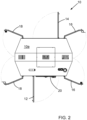
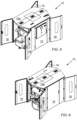
- FIGURES 1 through 6 show six different views of an embodiment 10 of an exemplary cooking-oil filter system (also referred to by reference number 10) for cleaning cooking oil from a food-fryer 24 (see FIGURE 7 ).
- FIGURE 1 is a perspective view of embodiment 10.
- Embodiment 10 includes an enclosure 10e which has a plurality of access doors as illustrated in FIGURES 1-6 , and a programmable controller 20 which includes memory (not explicitly shown), a graphical user interface 22 with a display 22d, and software programmed for controlling filter system 10.
- display 22d is a touch screen.
- FIGURE 2 is a top-view elevation drawing of embodiment 10, and FIGURES 3 through 6 show embodiment 10 in perspective as viewed from four different directions to illustrate the plurality of doors included in enclosure 10e.
- cooking-oil filter system 10 includes a left door 12, a right door 14, a pair of feed-end doors 16, and a pair of discharge-end doors 18. (Left and right are defined by viewing system 10 facing feed-end doors 16.)
- Each of the doors or pair of doors includes an electromagnetic door lock 12L, 14L, 16L, and 18L, respectively, which are controlled by controller 20 such that when a lock is in a locked state, the corresponding door or pair of doors is not able to be opened.
- FIGURE 7 is a fluid and mechanical schematic diagram of cooking-oil filtration system 10 showing the connectivity of the various system components.
- cooking-oil filtration system 10 includes a filter chamber 10c which includes a lower platen 40 and an upper platen 42.
- a filter-chamber actuator 46 moves upper platen 42 between open and closed positions, and a pair of platen position switches 48 indicate the open/closed state of upper platen 42.
- a filter-chamber pressure sensor 54 senses the pressure in filter chamber 10c and provides an additional indication of the operational state of filter chamber 10c.
- Filter chamber 10c may include an airbag (not shown) to work in conjunction with actuator 46 to assist in the sealing of filter chamber 10c while chamber 10c is under operating pressures.
- Cooking-oil filtration system 10 also includes a filter inlet line 10i, a filter outlet line 10o, a bleedoff line 36, a clean tank 26, a clean pump 28, and a filter pump 32.
- Filter inlet line 10i and bleedoff line 36 each include a flexible hose, 10h and 36h, respectively, to allow upper platen 42 to move between open and closed positions when moved by actuator 46.
- Actuator 46 may be a linear or rotary pneumatic, hydraulic or electrical actuator as desired; actuator 46 in embodiment 10 is an air cylinder.
- Cooking-oil filtration system 10 further includes a clean-media roller 44 holding clean media 44m, a spent-media roller 50, and a reroller 52 for removing spent media and installing clean media 44m in filter chamber 10c.
- Filter pump 32 pumps cooking oil from a fryer 24 through a fryer outlet line 24o to cooking-oil filtration system 10 through an inlet/bypass valve 34 which directs flow of clean cooking oil to filter chamber 10c through filter inlet line 10i.
- filter-chamber position sensor 48 in embodiment 10, platen position switches, also 48
- pressure provided by filter pump 32 drives cooking oil through media 44m in filter chamber 10c and through filter outlet line 10o into clean tank 26. Clean cooking oil is then pumped by clean pump 28 into fryer 24 through a clean supply valve 30 and a fryer inlet line 24i.
- bypass valve 34 may be used to redirect cooking oil into clean tank 26 without flowing through filter media 44m.
- Bypass valve 34 may be used to redirect cooking oil from fryer outlet line 24o directly into clean tank 26 through a first bypass line 10b.
- a bleedoff valve 38 may be used to vent cake-drying air and cooking oil directly into clean tank 26 through bleedoff line hose 36h and bleedoff lines 36 and 36b before opening filter chamber 10c.
- Cooking-oil filtration system 10 also includes components used to dry the cake and discharge spent media 44m, including a cake dry valve 56, a cake cooling valve 62, and a cake discharge hopper 60.
- cake dry valve 56 is opened to provide pressurized air from plant air supply 58 into upper platen 42 to dry the filter cake, driving free liquid above the filter cake through the filter cake.
- actuator 46 is used to raise upper platen 42 to open filter chamber 10c, and the filter cake is discharged into cake discharge hopper 60 where it is cooled by opening cake cooling valve 62 which sprays water from plant water supply 64 to cool the discharged filter cake.
- Cooking-oil filtration system 10 may be used in a facility which includes an optional external (user-supplied) bypass valve 66 which redirects cooking oil from fryer 24 through an external bypass line 66b back to fryer 24 without cooking oil passing through filter chamber 10c.
- bypass valve 66 is facility-controlled separately from controller 20; however, valve 66 provides a feedback signal to controller 20 with an indication of its position. Valve 66 is thus also represented by dotted lines in FIGURE 8B .
- FIGURE 8A illustrates schematically the association between door locks 12L, 14L, 16L, and 18L with the corresponding doors 12, 14, 16, and 18 in enclosure 10e.
- FIGURE 8B is a functional block diagram of the electrical/electronic systems in cooking-oil filtration system 10.
- Programmable controller 20 is shown with indications of system connectivity shown with arrows having either one arrowhead (flow of signals in only one direction) or two arrowheads (bi-directional flow of signals); such lines do not represent a particular type of wire connection but rather the flow of information or signals.
- door locks 12L, 14L, 16L, and 18L may be MGL Non-Contact RFID Coded Locking Safety Switches manufactured by IDEM Safety Switches Limited, headquartered in Wigan, United Kingdom.
- Such switches include an electromagnetic locking actuator and a switch to indicate the state of the locking mechanism, these two separate functions representing the bi-directionality of the connections to the door locks.
- Signals which control the locking and unlocking of doors 12, 14, 16, and 18 flow to the actuators of door locks 12L, 14L, 16L, and 18L while indications of the lock state of such locks flow back from the switches therein to controller 20.
- the connectivity is based on information flow within the system.
- door locks 12L, 14L, 16L, and 18L are shown in a parallel structure, but such door locks may be physically connected in parallel if desired without affecting the information or signal connectivity representations as shown in FIGURE 8 .
- FIGURE 8B In addition to door locks 12L, 14L, 16L, and 18L and controller 20, the block diagram of FIGURE 8B includes clean pump 28, filter pump 32, and reroller 52, all of which are connected to controller 20 with bi-directional connections. Clean pump 28, filter pump 32, and reroller 52 are each configured such that motor motion is sensed, providing feedback information on the state of these devices to controller 20. Platen position switches 48 (filter-chamber position sensor, also 48) provide position feedback information for platen 42; thus the arrows between controller 20 and actuator 46 and switches 48 are shown in one direction.
- controller 20 Also connected to controller 20 are clean supply valve 30, cake dry valve 56, cake cooling valve 62, input/bypass valve 34, and bleedoff valve 38, the latter two of these valves being connected bi-directionally to controller 20 to provide system 10 with an indication of valve state.
- a feedback signal from external bypass valve 66 is also connected to controller 20 as described above.
- FIGURE 8B includes platen position switches 48 and pressure sensor 54, both of which provide upper platen 42 position and chamber 10c pressure, respectively, to controller 20, and graphical user interface 22 which is bi-directionally connected to controller 20 since it includes touch-screen display 22d, both an output and input device.
- enclosure 10e, controller 20, and the system components shown in FIGURES 7 , 8A, and 8B are configured to provide operator safety by preventing access to the inside of enclosure 10e when cooking-oil filtration system 10 is in an unsafe operational state.
- an unsafe operational state is defined as one or more of the following conditions being true: (a) at least one electrically-controlled pump is moving; (b) the pressure in filter chamber 10c is above a preset threshold; (c) the position of upper platen 42 is such that filter chamber 10c is closed; and (c) media discharge reroller 52 is moving. Only when certain subsets or all of these conditions are false can the door locks 12L, 14L, 16L, and 18L be placed in unlocked states by controller 20.
- the at least one electrically-controlled pump includes filter pump 32 and clean pump 28.
- the preset threshold may be about 2psi above atmospheric pressure.
- controller 20 Such operational performance is controlled by programmable controller 20, and in addition to programs loaded into controller 20, the programming of controller 20 includes entry of operating system setpoints and other control inputs using graphical user interface 22 and display 22d. Such interaction is described in detail in the sections below.
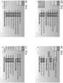
- FIGURES 9-22 are a set of screenshots from display 22d illustrating a number of different screens which are generated by programmable controller 20 during operation of cooking-oil filter system 10.
- the terms "screenshot of an embodiment of " are dropped but all such figures are to be regarded only as examples of possible embodiments of such screens generated by controller 20 during operation of system 10.
- FIGURE 9 illustrates a main screen of display 22d of graphical user interface 22.
- Such main screen provides a user with high-level control of system 10 such as control power, system auto start/stop, user login/logout, platen control, alarm control, and a show-menu control.
- FIGURE 10 shows such a menu being displayed on the main screen with various control options which will be described further below.
- the Menu arrow control which displays the menu when touched on display 22d (a touch screen in embodiment 10)
- the lower right corners of FIGURES 9 and 10 also include Alarm Silence and Alarm Reset controls.
- the Alarm Silence and Alarm Reset controls are labeled with a checkmark icon and a curved left-pointing arrow, respectively.
- FIGURE 11 depicts an operator controls screen with controls for the following: stop feed/start dry, abort dry cycle, clean-in-place control, fryer bypass control, media jog control, cake cooling control, and door-lock controls.
- a top-view schematic depicts door status. The operator controls screen is reached by touching the "Operator Controls" item in the menu.
- FIGURES 12 and 13 show screens which provide pump control and information on pump status for filter pump 32 and clean pump 28, respectively.
- FIGURE 12 and several other later screens in this series of screenshots display an indication of filter and pump run time.
- FIGURE 13 also includes some operational and setpoint data as shown.
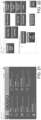
- FIGURE 14 illustrates a display of filter-cycle history data
- FIGURE 15 shows a filter status screen, displaying a number of component status indicators as illustrated.
- FIGURE 16 is a screenshot of an embodiment of an active-alarm status screen, in this illustration displaying an exemplary "out of media" event at the time at which such event occurred.
- FIGURES 17-20 are screenshots of first, second, third, and fourth filter-setup screens, respectively.
- a number of operational parameters are available to be set by the user as illustrated, such as machine pressure and media count settings ( FIGURE 17 ), filter pump speed settings ( FIGURES 18-19 ), filter cake cooling and fryer bypass settings ( FIGURE 19 ), and feed cycle and filter cake dry cycle settings ( FIGURE 20).
- FIGURES 17-18 and 20 also display some operational current values.
- media count corresponds to the length of clean media 44m moved into filter-chamber 10c as a filter cake is discharged into cake discharge hopper 60.
- FIGURE 21 is a screenshot of an embodiment of a systems settings setup screen which makes available high-level system settings to the user. Such settings are common to numerous computer-controlled systems and are well-known to those skilled in this technical field.
- FIGURE 22 is a screenshot of an embodiment of an override test screen which provides a user with controls for overriding the automated operation of certain filter components helpful for maintenance and troubleshooting functions. As with the screenshot of FIGURE 21 , such controls are common to numerous computer-controlled systems and are well-known to those skilled in this technical field.
- the present invention provides an extremely important safety feature which prevents a user from being exposed to cooking oil at the high pressures utilized in such filtration systems.
- programmable controller 20 is configured such that the unlocking of doors 12, 14, 16, and 18 is permitted only if (a) filter pump 32 and clean pump 28 are off (no pump motion), (b) the pressure in filter chamber 10c is below the preset threshold (2psi above atmospheric pressure in embodiment 10), filter chamber 10c is open, and reroller 52 is stopped.
- controller 20 may be configured to permit unlocking of doors 12, 14, 16, and 18 only if (1) clean pump 28 is off, (2) the pressure in filter chamber 10c is below the preset threshold, and (3) reroller 52 is stopped.
- cooking-oil filtration system 10 may require a subset of the above-listed conditions to be satisfied in order for controller 20 to permit unlocking of doors 12, 14, 16, and 18.
- unlocking the doors further requires that both the filter and clean pumps are off. In some of these embodiments, unlocking the doors further requires that the filter chamber is open.
- unlocking the doors further requires that the discharge reroller is stopped.
- the predetermined pressure is 2psi above atmospheric pressure.
- the cooking-oil filtration system further includes an external bypass valve configured to provide an external bypass from the cooking apparatus to a clean tank upstream of the cooking apparatus and an external-bypass-valve status signal to the controller.
- the at least one pump is the clean pump and unlocking the doors further requires that the external bypass valve be in a bypass mode.
Landscapes
- Engineering & Computer Science (AREA)
- Food Science & Technology (AREA)
- Frying-Pans Or Fryers (AREA)
- Lubrication Of Internal Combustion Engines (AREA)
- Fluid-Pressure Circuits (AREA)
Claims (7)
- Speiseöl-Filtrationssystem (10) für ein automatisches Kochgerät, das ein Feststoff-Trennfilter zum Reinigen von Speiseöl aus einer Speisefritteuse (24) und zum Rückführen von Öl zum Kochgerät aufweist, wobei das System folgendes umfasst:ein Feststoff-Trennfilter-Gehäuse (10e), das eine Mehrzahl von Türen (12, 14, 16, 18) aufweist, die elektronisch gesteuerte Verriegelungen (12L, 14L, 16L, 18L) mit einer Verriegelungszustands-Rückmeldefunktion aufweisen;eine programmierbare Steuerung (20) mit einem Speicher und einer Software zur Steuerung des Filtrationssystems und einer graphischen Benutzeroberfläche (22);eine Filterpumpe (32) und eine Reinigungspumpe (28), die jeweils elektronisch gesteuert sind;eine Filterkammer (10c) und eine elektronisch gesteuerte Filterkammer-Betätigungseinrichtung (46);einen Filterkammer-Positionssensor (48);eine elektronisch gesteuerte Medium-Wechselrolle (52);einen Filterkammer-Drucksensor (54); undmindestens eine Anzeigeeinrichtung (22d), die die graphische Benutzeroberfläche (22) abbildet, mit einer Mehrzahl von Bildschirmen mit Symbolen für die Interaktion mit einem Bediener, wobei jedes der Symbole eine Systemeinstellung, einen Status, und Vorgänge darstellt, und wobei die Bildschirme umfassen:• einen Haupt-Bildschirm mit einem Feld aus übergeordneten Systemsteuerungsfunktionen;• einen Bediener-Steuerungsbildschirm, der ein Feld von Symbolen anzeigt, das eine Mehrzahl von Filterbetätigungs-Steuerungsfunktionen darstellt, die Türverriegelungs-Steuerungsfunktionen umfassen, die den Türverriegelungsstatus anzeigen und das Verriegeln und Entriegeln der Türen steuern, wobei ein derartiges Entriegeln nur dann möglich ist, wenn mindestens eine Pumpe ausgeschaltet ist und der Filterkammerdruck unter einem vorbestimmten Druck liegt;• einen oder mehrere Status-Bildschirme, die den Status eines Filterbetriebs anzeigen; und• einen oder mehrere Einstellungs-Bildschirme zum Einstellen der Filter-Betriebsparameter.
- Speiseöl-Filtrationssystem nach Anspruch 1, wobei das Entriegeln der Türen (12, 14, 16, 18) weiterhin erfordert, dass sowohl die Filter- als auch die Reinigungspumpe (32, 28) ausgeschaltet sind.
- Speiseöl-Filtrationssystem nach Anspruch 2, wobei das Entriegeln der Türen (12, 14, 16, 18) weiterhin erfordert, dass die Filterkammer (10c) geöffnet ist.
- Speiseöl-Filtrationssystem nach Anspruch 3, wobei das Entriegeln der Türen (12, 14, 16, 18) weiterhin erfordert, dass die Wechselrolle (52) angehalten ist.
- Speiseöl-Filtrationssystem nach Anspruch 1, wobei der vorbestimmte Druck 2 psi über dem Umgebungsdruck liegt.
- Speiseöl-Filtrationssystem nach Anspruch 1, das des Weiteren ein externes Bypass-Ventil (34) umfasst, das dazu eingerichtet ist, (a) Speiseöl zu dem Kochgerät zurückzuführen, ohne die Filterkammer (10c) zu durchlaufen, und (b) ein externes Bypass-Ventil-Statussignal an die Steuerung (20) zu übertragen.
- Speiseöl-Filtrationssystem nach Anspruch 6, wobei die mindestens eine Pumpe eine Reinigungspumpe (28) ist und das Entriegeln der Türen (12, 14, 16, 18) weiterhin erfordert, dass sich das externe Bypass-Ventil (34) in einem Bypass-Modus befindet.
Applications Claiming Priority (2)
| Application Number | Priority Date | Filing Date | Title |
|---|---|---|---|
| US16/710,036 US11191389B2 (en) | 2019-12-11 | 2019-12-11 | Oil-filtration system with electronic safety locking system |
| PCT/US2020/064562 WO2021119461A1 (en) | 2019-12-11 | 2020-12-11 | Oil-filtration system with electronic safety locking system |
Publications (4)
| Publication Number | Publication Date |
|---|---|
| EP4069047A1 EP4069047A1 (de) | 2022-10-12 |
| EP4069047A4 EP4069047A4 (de) | 2022-12-28 |
| EP4069047B1 true EP4069047B1 (de) | 2023-08-09 |
| EP4069047C0 EP4069047C0 (de) | 2023-08-09 |
Family
ID=76316351
Family Applications (1)
| Application Number | Title | Priority Date | Filing Date |
|---|---|---|---|
| EP20899978.9A Active EP4069047B1 (de) | 2019-12-11 | 2020-12-11 | Öl-filtrationssystem mit elektronischem sicherheitsverriegelungssystem |
Country Status (5)
| Country | Link |
|---|---|
| US (1) | US11191389B2 (de) |
| EP (1) | EP4069047B1 (de) |
| AU (1) | AU2020403131B2 (de) |
| ES (1) | ES2961929T3 (de) |
| WO (1) | WO2021119461A1 (de) |
Families Citing this family (2)
| Publication number | Priority date | Publication date | Assignee | Title |
|---|---|---|---|---|
| US20210194849A1 (en) * | 2019-12-19 | 2021-06-24 | Vmware, Inc. | Scalable visualization of network flows |
| WO2024187250A1 (pt) * | 2023-03-16 | 2024-09-19 | Oliveira Adao Jesus De | Sistema e método para controle de fritadeiras |
Family Cites Families (6)
| Publication number | Priority date | Publication date | Assignee | Title |
|---|---|---|---|---|
| US3563158A (en) * | 1969-04-28 | 1971-02-16 | Cheftron Inc | Pressure cooking apparatus |
| US8186265B2 (en) * | 2005-08-08 | 2012-05-29 | Ron's Enterprises, Inc. | Device to efficiently cook food |
| US20090039004A1 (en) * | 2007-08-07 | 2009-02-12 | Bill Andersen Consulting Llc | Automatic oil filtration and treatment with level control and system heating during filtration |
| WO2010129651A2 (en) * | 2009-05-05 | 2010-11-11 | Spinfry, Inc. | Cooking device |
| US9114336B2 (en) * | 2012-01-17 | 2015-08-25 | Oberlin Filter Company | Oil-filtration system with oil/air separation for automated food-fryers |
| US11317762B2 (en) * | 2018-05-07 | 2022-05-03 | Pitco Frialator, Inc. | Multi-bank cooking system |
-
2019
- 2019-12-11 US US16/710,036 patent/US11191389B2/en active Active
-
2020
- 2020-12-11 ES ES20899978T patent/ES2961929T3/es active Active
- 2020-12-11 EP EP20899978.9A patent/EP4069047B1/de active Active
- 2020-12-11 WO PCT/US2020/064562 patent/WO2021119461A1/en not_active Ceased
- 2020-12-11 AU AU2020403131A patent/AU2020403131B2/en active Active
Also Published As
| Publication number | Publication date |
|---|---|
| EP4069047A1 (de) | 2022-10-12 |
| US11191389B2 (en) | 2021-12-07 |
| US20210177208A1 (en) | 2021-06-17 |
| AU2020403131B2 (en) | 2022-09-08 |
| EP4069047A4 (de) | 2022-12-28 |
| WO2021119461A1 (en) | 2021-06-17 |
| EP4069047C0 (de) | 2023-08-09 |
| AU2020403131A1 (en) | 2022-08-04 |
| ES2961929T3 (es) | 2024-03-14 |
Similar Documents
| Publication | Publication Date | Title |
|---|---|---|
| EP4069047B1 (de) | Öl-filtrationssystem mit elektronischem sicherheitsverriegelungssystem | |
| EP0281328A1 (de) | Flüssigkeitsfiltersystem | |
| RU2713934C2 (ru) | Устройство и способ для запуска одного или более скребков в технологический поток | |
| EP3519361B1 (de) | System zur regelung von wasser für industrielle nahrungsverarbeitung | |
| CN109789557B (zh) | 用于具有受控制的运动驱动装置的工业机器的控制设备和控制方法 | |
| US10677032B1 (en) | Electric submersible pump intake system, apparatus, and method | |
| US6354327B1 (en) | Automatic position-control valve assembly | |
| US9744486B2 (en) | Filter device | |
| DE102007017274A1 (de) | Verfahren zur Lageerkennung eines Verschlusselements in einer Wasserweiche | |
| JP7518074B2 (ja) | 安全システムインターフェース及び安全システムインターフェースを備える材料試験システム | |
| WO2015178818A1 (en) | Proceeding for flushing of pipes at hydraulic systems and a plant for the flushing | |
| DE3836530C2 (de) | ||
| EP2168687B1 (de) | Farbwechselventilanordnung mit Sensoren | |
| EP3023849A1 (de) | Konfigurierbarer sicherheits-logik-solver | |
| US12290766B2 (en) | Method and apparatus for water filtration | |
| EP3662985B1 (de) | Reinigungsvorrichtung für schlauchfilter | |
| EP1510698B1 (de) | Trockenlaufschutz | |
| CN110630804A (zh) | 一种具有除杂功能的安全可靠性高的电磁阀 | |
| US12180092B2 (en) | System for controlling water used for industrial food processing | |
| WO2003045574A1 (en) | Apparatus and method for filling a painting robot canister | |
| US8282360B2 (en) | Pneumatically operated reciprocating pump | |
| CN220473869U (zh) | 用于安全限制电动机运动的装置 | |
| DE102018006584B4 (de) | Steuervorrichtung und Steuerverfahren für Automatikfilter, sowie Filtersystem umfassend einen Automatikfilter und die genannte Steuervorrichtung | |
| JPH05166086A (ja) | プラント監視装置 | |
| CN208770947U (zh) | 一种人工智能型在线排渣自洁式柔刀过滤器 |
Legal Events
| Date | Code | Title | Description |
|---|---|---|---|
| STAA | Information on the status of an ep patent application or granted ep patent |
Free format text: STATUS: THE INTERNATIONAL PUBLICATION HAS BEEN MADE |
|
| PUAI | Public reference made under article 153(3) epc to a published international application that has entered the european phase |
Free format text: ORIGINAL CODE: 0009012 |
|
| STAA | Information on the status of an ep patent application or granted ep patent |
Free format text: STATUS: REQUEST FOR EXAMINATION WAS MADE |
|
| 17P | Request for examination filed |
Effective date: 20220707 |
|
| AK | Designated contracting states |
Kind code of ref document: A1 Designated state(s): AL AT BE BG CH CY CZ DE DK EE ES FI FR GB GR HR HU IE IS IT LI LT LU LV MC MK MT NL NO PL PT RO RS SE SI SK SM TR |
|
| A4 | Supplementary search report drawn up and despatched |
Effective date: 20221129 |
|
| RIC1 | Information provided on ipc code assigned before grant |
Ipc: B01D 35/147 20060101ALI20221123BHEP Ipc: B01D 33/80 20060101ALI20221123BHEP Ipc: A47J 37/12 20060101AFI20221123BHEP |
|
| GRAP | Despatch of communication of intention to grant a patent |
Free format text: ORIGINAL CODE: EPIDOSNIGR1 |
|
| STAA | Information on the status of an ep patent application or granted ep patent |
Free format text: STATUS: GRANT OF PATENT IS INTENDED |
|
| DAV | Request for validation of the european patent (deleted) | ||
| DAX | Request for extension of the european patent (deleted) | ||
| INTG | Intention to grant announced |
Effective date: 20230303 |
|
| GRAS | Grant fee paid |
Free format text: ORIGINAL CODE: EPIDOSNIGR3 |
|
| GRAA | (expected) grant |
Free format text: ORIGINAL CODE: 0009210 |
|
| STAA | Information on the status of an ep patent application or granted ep patent |
Free format text: STATUS: THE PATENT HAS BEEN GRANTED |
|
| AK | Designated contracting states |
Kind code of ref document: B1 Designated state(s): AL AT BE BG CH CY CZ DE DK EE ES FI FR GB GR HR HU IE IS IT LI LT LU LV MC MK MT NL NO PL PT RO RS SE SI SK SM TR |
|
| REG | Reference to a national code |
Ref country code: GB Ref legal event code: FG4D |
|
| REG | Reference to a national code |
Ref country code: CH Ref legal event code: EP |
|
| REG | Reference to a national code |
Ref country code: IE Ref legal event code: FG4D |
|
| REG | Reference to a national code |
Ref country code: DE Ref legal event code: R096 Ref document number: 602020015639 Country of ref document: DE |
|
| U01 | Request for unitary effect filed |
Effective date: 20230825 |
|
| U07 | Unitary effect registered |
Designated state(s): AT BE BG DE DK EE FI FR IT LT LU LV MT NL PT SE SI Effective date: 20230901 |
|
| PG25 | Lapsed in a contracting state [announced via postgrant information from national office to epo] |
Ref country code: GR Free format text: LAPSE BECAUSE OF FAILURE TO SUBMIT A TRANSLATION OF THE DESCRIPTION OR TO PAY THE FEE WITHIN THE PRESCRIBED TIME-LIMIT Effective date: 20231110 |
|
| PG25 | Lapsed in a contracting state [announced via postgrant information from national office to epo] |
Ref country code: IS Free format text: LAPSE BECAUSE OF FAILURE TO SUBMIT A TRANSLATION OF THE DESCRIPTION OR TO PAY THE FEE WITHIN THE PRESCRIBED TIME-LIMIT Effective date: 20231209 |
|
| U20 | Renewal fee for the european patent with unitary effect paid |
Year of fee payment: 4 Effective date: 20231221 |
|
| PG25 | Lapsed in a contracting state [announced via postgrant information from national office to epo] |
Ref country code: RS Free format text: LAPSE BECAUSE OF FAILURE TO SUBMIT A TRANSLATION OF THE DESCRIPTION OR TO PAY THE FEE WITHIN THE PRESCRIBED TIME-LIMIT Effective date: 20230809 Ref country code: NO Free format text: LAPSE BECAUSE OF FAILURE TO SUBMIT A TRANSLATION OF THE DESCRIPTION OR TO PAY THE FEE WITHIN THE PRESCRIBED TIME-LIMIT Effective date: 20231109 Ref country code: IS Free format text: LAPSE BECAUSE OF FAILURE TO SUBMIT A TRANSLATION OF THE DESCRIPTION OR TO PAY THE FEE WITHIN THE PRESCRIBED TIME-LIMIT Effective date: 20231209 Ref country code: HR Free format text: LAPSE BECAUSE OF FAILURE TO SUBMIT A TRANSLATION OF THE DESCRIPTION OR TO PAY THE FEE WITHIN THE PRESCRIBED TIME-LIMIT Effective date: 20230809 Ref country code: GR Free format text: LAPSE BECAUSE OF FAILURE TO SUBMIT A TRANSLATION OF THE DESCRIPTION OR TO PAY THE FEE WITHIN THE PRESCRIBED TIME-LIMIT Effective date: 20231110 |
|
| PG25 | Lapsed in a contracting state [announced via postgrant information from national office to epo] |
Ref country code: PL Free format text: LAPSE BECAUSE OF FAILURE TO SUBMIT A TRANSLATION OF THE DESCRIPTION OR TO PAY THE FEE WITHIN THE PRESCRIBED TIME-LIMIT Effective date: 20230809 |
|
| REG | Reference to a national code |
Ref country code: ES Ref legal event code: FG2A Ref document number: 2961929 Country of ref document: ES Kind code of ref document: T3 Effective date: 20240314 |
|
| PG25 | Lapsed in a contracting state [announced via postgrant information from national office to epo] |
Ref country code: SM Free format text: LAPSE BECAUSE OF FAILURE TO SUBMIT A TRANSLATION OF THE DESCRIPTION OR TO PAY THE FEE WITHIN THE PRESCRIBED TIME-LIMIT Effective date: 20230809 Ref country code: RO Free format text: LAPSE BECAUSE OF FAILURE TO SUBMIT A TRANSLATION OF THE DESCRIPTION OR TO PAY THE FEE WITHIN THE PRESCRIBED TIME-LIMIT Effective date: 20230809 Ref country code: CZ Free format text: LAPSE BECAUSE OF FAILURE TO SUBMIT A TRANSLATION OF THE DESCRIPTION OR TO PAY THE FEE WITHIN THE PRESCRIBED TIME-LIMIT Effective date: 20230809 Ref country code: SK Free format text: LAPSE BECAUSE OF FAILURE TO SUBMIT A TRANSLATION OF THE DESCRIPTION OR TO PAY THE FEE WITHIN THE PRESCRIBED TIME-LIMIT Effective date: 20230809 |
|
| REG | Reference to a national code |
Ref country code: DE Ref legal event code: R097 Ref document number: 602020015639 Country of ref document: DE |
|
| PLBE | No opposition filed within time limit |
Free format text: ORIGINAL CODE: 0009261 |
|
| STAA | Information on the status of an ep patent application or granted ep patent |
Free format text: STATUS: NO OPPOSITION FILED WITHIN TIME LIMIT |
|
| 26N | No opposition filed |
Effective date: 20240513 |
|
| REG | Reference to a national code |
Ref country code: CH Ref legal event code: PL |
|
| PG25 | Lapsed in a contracting state [announced via postgrant information from national office to epo] |
Ref country code: MC Free format text: LAPSE BECAUSE OF FAILURE TO SUBMIT A TRANSLATION OF THE DESCRIPTION OR TO PAY THE FEE WITHIN THE PRESCRIBED TIME-LIMIT Effective date: 20230809 |
|
| PG25 | Lapsed in a contracting state [announced via postgrant information from national office to epo] |
Ref country code: MC Free format text: LAPSE BECAUSE OF FAILURE TO SUBMIT A TRANSLATION OF THE DESCRIPTION OR TO PAY THE FEE WITHIN THE PRESCRIBED TIME-LIMIT Effective date: 20230809 |
|
| REG | Reference to a national code |
Ref country code: IE Ref legal event code: MM4A |
|
| PG25 | Lapsed in a contracting state [announced via postgrant information from national office to epo] |
Ref country code: IE Free format text: LAPSE BECAUSE OF NON-PAYMENT OF DUE FEES Effective date: 20231211 |
|
| PG25 | Lapsed in a contracting state [announced via postgrant information from national office to epo] |
Ref country code: CH Free format text: LAPSE BECAUSE OF NON-PAYMENT OF DUE FEES Effective date: 20231231 |
|
| PG25 | Lapsed in a contracting state [announced via postgrant information from national office to epo] |
Ref country code: IE Free format text: LAPSE BECAUSE OF NON-PAYMENT OF DUE FEES Effective date: 20231211 Ref country code: CH Free format text: LAPSE BECAUSE OF NON-PAYMENT OF DUE FEES Effective date: 20231231 |
|
| U20 | Renewal fee for the european patent with unitary effect paid |
Year of fee payment: 5 Effective date: 20241227 |
|
| PGFP | Annual fee paid to national office [announced via postgrant information from national office to epo] |
Ref country code: ES Payment date: 20250102 Year of fee payment: 5 |
|
| PG25 | Lapsed in a contracting state [announced via postgrant information from national office to epo] |
Ref country code: CY Free format text: LAPSE BECAUSE OF FAILURE TO SUBMIT A TRANSLATION OF THE DESCRIPTION OR TO PAY THE FEE WITHIN THE PRESCRIBED TIME-LIMIT; INVALID AB INITIO Effective date: 20201211 |
|
| PG25 | Lapsed in a contracting state [announced via postgrant information from national office to epo] |
Ref country code: HU Free format text: LAPSE BECAUSE OF FAILURE TO SUBMIT A TRANSLATION OF THE DESCRIPTION OR TO PAY THE FEE WITHIN THE PRESCRIBED TIME-LIMIT; INVALID AB INITIO Effective date: 20201211 |
|
| PG25 | Lapsed in a contracting state [announced via postgrant information from national office to epo] |
Ref country code: TR Free format text: LAPSE BECAUSE OF FAILURE TO SUBMIT A TRANSLATION OF THE DESCRIPTION OR TO PAY THE FEE WITHIN THE PRESCRIBED TIME-LIMIT Effective date: 20230809 |
|
| PGFP | Annual fee paid to national office [announced via postgrant information from national office to epo] |
Ref country code: GB Payment date: 20251229 Year of fee payment: 6 |
|
| U20 | Renewal fee for the european patent with unitary effect paid |
Year of fee payment: 6 Effective date: 20251229 |