EP4068948B1 - Erntevorsatzkopf für die forstwirtschaft und verfahren zum bestimmen der dicke eines baumstammes in einem erntevorsatz für die forstwirtschaft - Google Patents
Erntevorsatzkopf für die forstwirtschaft und verfahren zum bestimmen der dicke eines baumstammes in einem erntevorsatz für die forstwirtschaft Download PDFInfo
- Publication number
- EP4068948B1 EP4068948B1 EP20817338.5A EP20817338A EP4068948B1 EP 4068948 B1 EP4068948 B1 EP 4068948B1 EP 20817338 A EP20817338 A EP 20817338A EP 4068948 B1 EP4068948 B1 EP 4068948B1
- Authority
- EP
- European Patent Office
- Prior art keywords
- tree trunk
- limbing
- harvesting head
- measuring
- thickness
- Prior art date
- Legal status (The legal status is an assumption and is not a legal conclusion. Google has not performed a legal analysis and makes no representation as to the accuracy of the status listed.)
- Active
Links
Images



Classifications
-
- A—HUMAN NECESSITIES
- A01—AGRICULTURE; FORESTRY; ANIMAL HUSBANDRY; HUNTING; TRAPPING; FISHING
- A01G—HORTICULTURE; CULTIVATION OF VEGETABLES, FLOWERS, RICE, FRUIT, VINES, HOPS OR SEAWEED; FORESTRY; WATERING
- A01G23/00—Forestry
- A01G23/02—Transplanting, uprooting, felling or delimbing trees
- A01G23/08—Felling trees
- A01G23/083—Feller-delimbers
-
- A—HUMAN NECESSITIES
- A01—AGRICULTURE; FORESTRY; ANIMAL HUSBANDRY; HUNTING; TRAPPING; FISHING
- A01G—HORTICULTURE; CULTIVATION OF VEGETABLES, FLOWERS, RICE, FRUIT, VINES, HOPS OR SEAWEED; FORESTRY; WATERING
- A01G23/00—Forestry
- A01G23/02—Transplanting, uprooting, felling or delimbing trees
- A01G23/095—Delimbers
-
- A—HUMAN NECESSITIES
- A01—AGRICULTURE; FORESTRY; ANIMAL HUSBANDRY; HUNTING; TRAPPING; FISHING
- A01G—HORTICULTURE; CULTIVATION OF VEGETABLES, FLOWERS, RICE, FRUIT, VINES, HOPS OR SEAWEED; FORESTRY; WATERING
- A01G3/00—Cutting implements specially adapted for horticultural purposes; Delimbing standing trees
- A01G3/08—Other tools for pruning, branching or delimbing standing trees
- A01G3/085—Motor-driven saws for pruning or branching
-
- G—PHYSICS
- G01—MEASURING; TESTING
- G01B—MEASURING LENGTH, THICKNESS OR SIMILAR LINEAR DIMENSIONS; MEASURING ANGLES; MEASURING AREAS; MEASURING IRREGULARITIES OF SURFACES OR CONTOURS
- G01B11/00—Measuring arrangements characterised by the use of optical techniques
- G01B11/02—Measuring arrangements characterised by the use of optical techniques for measuring length, width or thickness
- G01B11/04—Measuring arrangements characterised by the use of optical techniques for measuring length, width or thickness specially adapted for measuring length or width of objects while moving
- G01B11/046—Measuring arrangements characterised by the use of optical techniques for measuring length, width or thickness specially adapted for measuring length or width of objects while moving for measuring width
-
- G—PHYSICS
- G01—MEASURING; TESTING
- G01B—MEASURING LENGTH, THICKNESS OR SIMILAR LINEAR DIMENSIONS; MEASURING ANGLES; MEASURING AREAS; MEASURING IRREGULARITIES OF SURFACES OR CONTOURS
- G01B21/00—Measuring arrangements or details thereof, where the measuring technique is not covered by the other groups of this subclass, unspecified or not relevant
- G01B21/02—Measuring arrangements or details thereof, where the measuring technique is not covered by the other groups of this subclass, unspecified or not relevant for measuring length, width, or thickness
- G01B21/06—Measuring arrangements or details thereof, where the measuring technique is not covered by the other groups of this subclass, unspecified or not relevant for measuring length, width, or thickness specially adapted for measuring length or width of objects while moving
-
- G—PHYSICS
- G01—MEASURING; TESTING
- G01B—MEASURING LENGTH, THICKNESS OR SIMILAR LINEAR DIMENSIONS; MEASURING ANGLES; MEASURING AREAS; MEASURING IRREGULARITIES OF SURFACES OR CONTOURS
- G01B5/00—Measuring arrangements characterised by the use of mechanical techniques
- G01B5/0035—Measuring of dimensions of trees
-
- G—PHYSICS
- G01—MEASURING; TESTING
- G01B—MEASURING LENGTH, THICKNESS OR SIMILAR LINEAR DIMENSIONS; MEASURING ANGLES; MEASURING AREAS; MEASURING IRREGULARITIES OF SURFACES OR CONTOURS
- G01B11/00—Measuring arrangements characterised by the use of optical techniques
- G01B11/08—Measuring arrangements characterised by the use of optical techniques for measuring diameters
-
- G—PHYSICS
- G01—MEASURING; TESTING
- G01B—MEASURING LENGTH, THICKNESS OR SIMILAR LINEAR DIMENSIONS; MEASURING ANGLES; MEASURING AREAS; MEASURING IRREGULARITIES OF SURFACES OR CONTOURS
- G01B5/00—Measuring arrangements characterised by the use of mechanical techniques
- G01B5/08—Measuring arrangements characterised by the use of mechanical techniques for measuring diameters
- G01B5/12—Measuring arrangements characterised by the use of mechanical techniques for measuring diameters internal diameters
Definitions
- the present invention relates to a harvesting head for forestry and a method of determining a thickness of a tree trunk in a harvesting head.
- a harvesting head usually consists of a rigid frame to which there is attached a pair of front limbing knives, a pair of feeding rollers, a chain saw and sometimes one or two back limbing knives situated between the pair of feeding rollers and the chain saw.
- a harvesting head functions as such that it grips a tree by its trunk close to the ground. It then cuts through the trunk and fells the tree. The tree is then fed through the harvesting head, which limbs the tree as it passes therethrough. After feeding through certain lengths of the tree the fed-through parts are cut off, after which the tree is continued to be fed through. When the tree's trunk becomes too thin, the tree is let go off.
- harvesting heads are disclosed in WO00/15026A1 , WO2019/226088A1 , WO2009/157864A1 and WO2006/092469A1 .
- the limbing knives, the feeding rollers as well as the chain saw are all pivotally movable.
- the chain saw such that it can move against the tree trunk and saw it through.
- the feeding rollers such that they can grip the tree trunk and feed it through the harvesting head by rolling.
- the limbing knives such that they can enclose the trunk and press it against a gliding surface of the harvesting head.
- a gliding surface is a surface on the harvesting head's frame against which a tree trunk glides when it is fed through the harvesting head.
- the thickness of a fed through tree trunk is typically determined by measuring the position of a limbing knife or a feeding roller and relating its position to the frame of the harvesting head, typically the gliding surface. Since the tree trunk is pressed against the frame by either a limbing knife or a feeding roller, the position of the limbing knife or feeding roller will be related to the thickness of the fed through trunk.
- a method for determining a thickness of a tree trunk in a harvesting head for forestry comprising
- a tree trunk surface follower is a device which is arranged to follow the surface of a tree trunk held in a harvesting head, following the movement of the tree trunk surface while the tree trunk is fed through the harvesting head.
- the tree trunk surface follower may abut the tree trunk surface but does not need to.
- the tree trunk surface follower is placed as close to the tree trunk pressing device as possible, in the feeding direction of the tree trunk, such that the deviation of the tree trunk is determined as close to the measured thickness as possible.
- the dependence of the position of the tree trunk surface follower on the thickness of a tree trunk can be adjusted for.
- Themethod comprises determining a thickness of a tree trunk in a harvesting head for forestry, said harvesting head comprising
- the harvesting head further comprises a proximity sensor, and measuring the position of the tree trunk surface follower is done with the proximity sensor.
- the proximity sensor is a magneto-inductive sensor.
- the tree trunk surface follower is pressed against at least a portion of the half of the circumference of the tree trunk which is closest to the reference surface. In this manner the tree trunk surface follower follows the position of the tree trunk's surface, following the part of the tree trunk which is closest to the reference surface. This assures that the position of the tree trunk surface follower will be related to the deviation of the tree trunk from the reference surface.
- a method for determining a volume of a tree trunk in a harvesting head by determining a length and several thicknesses of the tree trunk. The determined thicknesses being spaced at a certain length interval. The volume being calculated based on the determined length and thicknesses. The thicknesses being determined according to the previously disclosed method. In this manner a more accurate volume of a tree trunk can be determined. The volume of the tree trunk will be adjusted for any inaccuracies coming from deviations from the reference surface of the tree trunk during volume determining.
- a harvesting head for forestry comprising a thickness measuring arrangement for measuring a measured thickness of a tree trunk, said thickness measuring arrangement comprising a tree trunk pressing device, for pressing said tree trunk in a direction towards a reference surface of the harvesting head , and a first measuring sensor arranged to measure the position of said tree trunk pressing device relative to said reference surface,
- the second measuring sensor is a magneto-inductive measuring sensor.
- the limbing member is arranged on a front side of a front plate of the harvesting head, and the second measuring sensor is arranged on a back side of the front plate, the back side being opposite to the front side
- the second measuring sensor comprises a first portion and a second portion, and the first portion is arranged on the front plate and the second portion is arranged on the limbing member.
- the front plate comprises a slit extending through the front plate from the front side to the back side,
- the tree trunk surface follower is arranged to follow at least a portion of the half of the circumference of the tree trunk which is closest to the reference surface.
- This embodiment has the advantage of assuring that the tree trunk surface follower follows the position of the tree trunk surface, following the part of the tree trunk which is closest to the reference surface, which in its turn assures that the position of the tree trunk surface follower is related to the deviation of the tree trunk from the reference surface.
- the tree trunk surface follower may be pressed towards the tree trunk by a compression spring, a torsion spring or a hydraulic piston.
- the tree trunk pressing device may comprise at least one limbing knife.
- the tree trunk surface follower may be linearly guided.
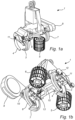
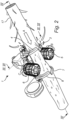
- the front limbing knives 3, 4 are used to limb a tree trunk 17 as well as to determine a thickness of it.
- the back limbing knives 7, 8 are also pivotally movable in a plane perpendicular to the feeding direction A of the tree trunk 17 and used to enclose a tree trunk 17 and press it in a direction towards the gliding surface 15.
- the limbing knives 3, 4, 7, 8 have the form of curved knives with the sharp end on the front side.
- An enclosed tree trunk 17 will have its limbs cut off by the limbing knives 3, 4, 7, 8 when fed through the harvesting head 1 in feeding direction A.
- the chain saw 10 is used to cut off limbed pieces of a tree trunk 17.
- the chain saw 10 is held inside a cover 9 and is pivotally movable in a plane perpendicular to the feeding direction A of the tree trunk 17.
- the tree trunk 17 is cut by moving the chain saw 10 through it.
- the limbing member 11 is curved. By this is meant that a portion of the limbing member 11 arranged to be closest to a tree trunk 17 fed through the harvesting head has a curved shape. This could be a sharp edge, which is comprised by the limbing member, configured to delimb a portion of the circumference of the tree trunk 17.
- a curved shape could be a continuous curve.
- a curved shape could be a combination of two or more straight lines or surfaces arranged at an angle relative each other.
- a curved shape could be a combination of a continuous curve and one or more straight lines or surfaces arranged at an angle relative each other.
- the limbing member is curved such that it is concave towards the tree trunk.
- the thickness T 1 , T 2 is determined by a thickness determining arrangement 18, which comprises the pair of front limbing knives 3, 4 and rotary encoders 19.
- the rotary encoders 19 are arranged to measure the angular position of the front limbing knives 3, 4.
- the angular position of the limbing knives 3, 4 is related to the gliding surface 15, and thereby a thickness of a tree trunk 17, through a conversion table which relates different angular positions of the front limbing knives 3, 4 to different thicknesses.
- the position of the limbing knives 3, 4, in relation to the gliding surface 15 will be directly related to the thickness of a tree trunk 17.
- the measured thickness T 1 , T 2 will be wrong.
- a common cause of measurement error is a deviation of the tree trunk 17 from the gliding surface 15. Such a deviation may occur if the tree trunk 17 is curved or if its surface is uneven, for example from a poorly cut off limb.
- FIG 4 shows a cross sectional view of the harvesting head 1 holding a tree trunk 17 from Figure 2 .
- the tree trunk 17 has an uneven surface.
- This unevenness has produced a deviation D of the tree trunk 17 from the gliding surface 15.
- This deviation D is what differs a measured thickness T from a corrected thickness T c .
- the corrected thickness T c being the measured thickness T corrected for the deviation D.
- the deviation is determined by a deviation measuring arrangement 20, which comprises the limbing member 11, a linear contact sensor 21, a rotational joint 25 and a torsion spring situated in the rotational joint 25.
- the limbing member 11 is pivotally coupled to the harvesting head 1 by rotational joint 25.
- the torsion spring presses the limbing member 11 towards the tree trunk 17 in a direction E by rotating the limbing member 11 in direction F.
- the linear contact sensor 21 is mechanically coupled to the limbing member 11 by connection 23.
- the linear contact sensor 21 measures the position of the limbing member 11. By measuring the position of the limbing member 11 it is possible to measure the deviation D. Since the limbing member 11 follows the surface of the tree trunk 17 its position can be related to the position of the surface which it follows. If the surface which the tree trunk surface follower follows is on the half of the circumference of the tree trunk 17 closest to the gliding surface 15, i.e.
- the length measuring wheel 13 is pivotally coupled to the harvesting head 1 such that it moves in direction G, when pressed towards the surface of the tree trunk 17.
- the length measuring wheel 13 is pressed towards the surface of the tree trunk 17 by means of a hydraulic cylinder 27.
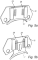
- Figure 5a and 5b show an alternative limbing member 11' to the one shown in Figures 1 through 4 .
- the limbing member 11' is linearly guided and pressed towards the tree trunk 17 in direction H by compression springs 29.
- the alternative limbing member's 11' position relative to the gliding surface 15 may be measured by a linear contact sensor mechanically coupled to the limbing member 11' or by a contact free linear sensor.
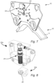
- the sensor 22 comprises a first portion 22a and a second portion 22b.
- the first portion 22a is arranged on the front plate 12, on the back side of the front plate.
- the second portion 22b is arranged on the limbing member 11.
- the front plate 12 comprises a slit 23.
- the slit 23 extends through the front plate 12 form the front side to the back side.
- the second portion of the sensor 22b is arranged in the slit 23.
- a corrected thickness T c of the tree trunk 17 is determined by determining a measured thickness T and a deviation D of the tree trunk 17 and calculating a corrected thickness T c based on the deviation D and the measured thickness T.
- the deviation D is determined by measuring the position of the limbing member 11, with linear contact sensor 21, and relating its position to the gliding surface 15.
- the position of the limbing member 11 being related to the gliding surface 15, and thereby a deviation D, through a conversion table which relates different positions of the limbing member 11 to different deviations D of a tree trunk 17 held in the harvesting head 1.
- the corrected thickness T c is calculated by subtracting the deviation D from the measured thickness T.
- the tree trunk pressing device may be any other limbing knife 3, 4, 7, 8. It does not need to be a pair of limbing knives, it may be more than a pair or just one knife. It may also be one or several feed rollers 5, 6.
- the tree trunk pressing device may be a device separate from a limbing knife.
- the tree trunk pressing device may be anything as long as it presses the tree trunk in a direction towards a reference surface.
- a tree trunk surface follower may instead of a limbing member 11, 11' be a measuring wheel 13.
- the tree trunk surface follower may be a device separate from a limbing member or length measuring wheel.
- a reference surface does not need to be a gliding surface, it could be a surface of any size, situated anywhere on the harvesting head as long as the tree trunk is pressed in a direction towards it and the position of a tree trunk pressing device and the position of a tree trunk surface follower is related to it.
- Several thicknesses of the tree trunk may be determined at several points on the tree trunk 17 as it is fed through the harvesting head 1, the points separated by a certain length interval, the interval may be 10 centimeters.
- the linear contact sensor 21 mechanically coupled to the limbing member 11 by connection 23, it is possible to use a contact free linear sensor, which would not need the connection 23. It is also possible to use an angle sensor positioned inside joint 25, the angle sensor could be a rotary encoder or an analog angle sensor. If the tree trunk surface follower is a measuring wheel 13, its position relative to the gliding surface 15 could be measured by a linear contact sensor coupled to the measuring wheel 13. It could also be measured by a contact free linear sensor or by an angle sensor such as a rotary encoder or analog angle sensor.
- a few alternatives to a tree trunk surface follower and devices pressing it towards a tree trunk surface has been disclosed.
- the devices can be combined with whichever tree trunk surface follower.
- a measuring wheel could also be pressed towards the tree trunk surface by a compression spring or a torsion spring.
- the deviation may also be determined by not only relating the position of the limbing member 11 to the gliding surface 15, but also by relating the position of the limbing member 11 to the measured thickness T of the tree trunk 17.
- the position of the limbing member 11 being related to the gliding surface 15, and thereby a deviation D, through a conversion table which relates different positions of the limbing member 11 as well as different measured thicknesses T to different deviations D of a tree trunk 17 held in the harvesting head 1.
Landscapes
- Life Sciences & Earth Sciences (AREA)
- Biodiversity & Conservation Biology (AREA)
- Ecology (AREA)
- Forests & Forestry (AREA)
- Environmental Sciences (AREA)
- Physics & Mathematics (AREA)
- General Physics & Mathematics (AREA)
- Botany (AREA)
- A Measuring Device Byusing Mechanical Method (AREA)
- Measurement Of Length, Angles, Or The Like Using Electric Or Magnetic Means (AREA)
- Length Measuring Devices With Unspecified Measuring Means (AREA)
- Measurement Of The Respiration, Hearing Ability, Form, And Blood Characteristics Of Living Organisms (AREA)
Claims (11)
- Verfahren zum Bestimmen einer Dicke eines Baumstammes (17) in einem Erntekopf (1) für die Forstwirtschaft, wobei der Erntekopf (1) Folgendes umfassteine Dickenmessanordnung zum Messen einer gemessenen Dicke (T) eines Baumstammes (17), wobei die Dickenmessanordnung Folgendes umfasst: eine Baumstammpressvorrichtung (3, 4, 7, 8) zum Pressen des Baumstammes (17) in Richtung auf eine Referenzfläche (15) des Erntekopfes (1) und einen ersten Messsensor (19), der angeordnet ist, um die Position der Baumstammpressvorrichtung (3, 4, 7, 8) relativ zu der Referenzfläche (15) zu messen, undeine Abweichungsmessanordnung zum Messen einer Abweichung (D) des Baumstammes (17) von der Referenzfläche (15),wobei die Abweichungsmessanordnung einen Baumstammoberflächenfolger (11, 13; 11') und einen zweiten Messsensor (21) umfasst, der angeordnet ist, um die Position des Baumstammoberflächenfolgers (11, 13; 11') zu messen,wobei der zweite Messsensor ein Näherungssensor ist, wobei der Baumstammoberflächenfolger ein Abästelement (11, 11') ist und wobei das Abästelement (11, 11') gekrümmt ist,wobei das Verfahren Folgendes umfasstPressen des Baumstammes (17) mit der Baumstammpressvorrichtung (3, 4, 7, 8) in Richtung der Referenzfläche (15) des Erntekopfes (1) undBestimmen einer gemessenen Dicke (T) durch Messen der Position der Baumstammpressvorrichtung (3, 4, 7, 8) mittels des ersten Messsensors (19) und Setzen der Position in Beziehung zur Referenzfläche (15),wobei das Verfahren ferner die folgenden Schritte umfasst Bestimmen einer Abweichung (D) des Baumstammes (17) von der Referenzfläche (15) durch Messen einer Position des gekrümmten Abästelements (11, 11') mittels des zweiten Messsensors (21) und Setzen der Position des gekrümmten Abästelements (11, 11') in Beziehung zur Referenzfläche (15), undBerechnen einer korrigierten Dicke (Tc) des Baumstammes (17) basierend auf der gemessenen Dicke (T) und der Abweichung (D),wobei das Bestimmen der Abweichung (D) ferner das Setzen der Position des gekrümmten Abästelements (11, 11') in Beziehung zur gemessenen Dicke (T) umfasst, undBestimmen der Abweichung (D) als Funktion der Position des gekrümmten Abästelements (11, 11'), einer Krümmung des Abästelements (11, 11') und der gemessenen Dicke (T).
- Verfahren nach Anspruch 1, wobei der Näherungssensor ein magnetisch-induktiver Sensor ist.
- Verfahren nach einem der vorhergehenden Ansprüche, umfassend das Pressen des Baumstammoberflächenfolgers (11, 13; 11') gegen mindestens einen Teil der Hälfte des Umfangs des Baumstammes (17), der der Referenzfläche (15) am nächsten liegt.
- Erntekopf (1) für die Forstwirtschaft, mit einer Dickenmessanordnung zum Messen einer gemessenen Dicke (T) eines Baumstammes (17), wobei die Dickenmessanordnung eine Baumstammpressvorrichtung (3, 4, 7, 8) zum Pressen des Baumstammes (17) in Richtung der Referenzfläche (15) des Erntekopfes (1) umfasst, und einen ersten Messsensor (19), der angeordnet ist, um die Position der Baumstammpressvorrichtung (3, 4, 7, 8) relativ zu der Referenzfläche (15) zu messen,wobei der Erntekopf (1) ferner Folgendes umfasst eine Abweichungsmessanordnung zum Messen einer Abweichung (D) des Baumstammes (17) von der Referenzfläche (15),wobei die Abweichungsmessanordnung einen Baumstammoberflächenfolger (11, 13; 11') und einen zweiten Messsensor (21) umfasst, der angeordnet ist, um die Position des Baumstammoberflächenfolgers (11, 13; 11') zu messen,wobei der Baumstammoberflächenfolger ein Abästelement (11, 11') ist,wobei der zweite Messsensor ein Näherungssensor ist,wobei das Abästelement (11, 11') an einer Vorderseite einer Frontplatte des Erntekopfes (1) angeordnet ist, dadurch gekennzeichnet, dassder zweite Messsensor auf einer Rückseite der Frontplatte angeordnet ist, wobei die Rückseite der Vorderseite gegenüberliegt,der zweite Messsensor einen ersten Abschnitt und einen zweiten Abschnitt umfasst, undder erste Abschnitt an der Frontplatte angeordnet ist und der zweite Abschnitt an dem Abästelement angeordnet ist.
- Erntekopf (1) nach Anspruch 4, wobei der zweite Messsensor ein magnetisch-induktiver Messsensor ist.
- Erntekopf (1) nach Anspruch 4 oder 5, wobei die Frontplatte einen Schlitz umfasst, der sich durch die Frontplatte von der Vorderseite zur Rückseite erstreckt, wobei der erste Abschnitt des zweiten Messsensors auf der Rückseite der Frontplatte angeordnet ist, und
der zweite Abschnitt des zweiten Messsensors in dem Schlitz angeordnet ist. - Erntekopf nach einem der Ansprüche 4 bis 6, wobei der Baumstammoberflächenfolger (11, 13; 11') so angeordnet ist, dass er mindestens einem Teil der Hälfte des Umfangs des Baumstammes (17) folgt, der der Referenzfläche (15) am nächsten ist.
- Erntekopf nach einem der Ansprüche 4 bis 7, wobei die Abweichungsmessanordnung eine Torsionsfeder, eine Druckfeder (29) oder einen Hydraulikkolben (27) umfasst.
- Erntekopf nach einem der Ansprüche 4 bis 8, wobei die Baumstammpressvorrichtung mindestens ein Abästmesser (3, 4, 7, 8) umfasst.
- Erntekopf nach einem der Ansprüche 4 bis 9, wobei der Baumstammoberflächenfolger (11, 13; 11') linear geführt wird.
- Erntekopf nach einem der Ansprüche 4 bis 9, wobei der Baumstammoberflächenfolger (11, 13; 11') schwenkbar mit dem Erntekopf (1) gekoppelt ist.
Applications Claiming Priority (2)
| Application Number | Priority Date | Filing Date | Title |
|---|---|---|---|
| SE1951383A SE544915C2 (en) | 2019-12-03 | 2019-12-03 | Harvesting head for forestry and a method for determining a thickness of a tree trunk in a harvesting head for forestry |
| PCT/EP2020/084293 WO2021110755A1 (en) | 2019-12-03 | 2020-12-02 | Harvesting head for forestry and a method for determining a thickness of a tree trunk in a harvesting head for forestry |
Publications (3)
| Publication Number | Publication Date |
|---|---|
| EP4068948A1 EP4068948A1 (de) | 2022-10-12 |
| EP4068948B1 true EP4068948B1 (de) | 2025-06-25 |
| EP4068948C0 EP4068948C0 (de) | 2025-06-25 |
Family
ID=73695058
Family Applications (1)
| Application Number | Title | Priority Date | Filing Date |
|---|---|---|---|
| EP20817338.5A Active EP4068948B1 (de) | 2019-12-03 | 2020-12-02 | Erntevorsatzkopf für die forstwirtschaft und verfahren zum bestimmen der dicke eines baumstammes in einem erntevorsatz für die forstwirtschaft |
Country Status (6)
| Country | Link |
|---|---|
| US (1) | US12317787B2 (de) |
| EP (1) | EP4068948B1 (de) |
| AU (1) | AU2020394817B2 (de) |
| CA (1) | CA3163180A1 (de) |
| SE (1) | SE544915C2 (de) |
| WO (1) | WO2021110755A1 (de) |
Citations (5)
| Publication number | Priority date | Publication date | Assignee | Title |
|---|---|---|---|---|
| EP0346308B1 (de) | 1988-06-06 | 1991-08-07 | Grangärde Maskin Ab | Baumentastungsvorrichtung |
| US5785101A (en) | 1995-11-14 | 1998-07-28 | Timberjack Inc. | Tree harvesting and processing head |
| WO2000015026A1 (en) | 1998-09-15 | 2000-03-23 | Timberjack Oy | A control arrangement and a method in a delimbing device |
| EP2265894B1 (de) | 2008-04-16 | 2018-06-06 | Log Max AB | Bestimmung der dicke eines baumstammes |
| EP2296852B1 (de) | 2008-06-25 | 2020-10-07 | Log Max AB | Verfahren und vorrichtung zur entastung von bäumen |
Family Cites Families (9)
| Publication number | Priority date | Publication date | Assignee | Title |
|---|---|---|---|---|
| FI106092B (fi) * | 1998-06-04 | 2000-11-30 | Ponsse Oyj | Puunrungon paksuuden mittausmenetelmä ja -laite |
| FI104531B (fi) * | 1998-09-15 | 2000-02-29 | Timberjack Oy | Karsintalaitteisto ja menetelmä karsintalaitteistossa |
| SE526942C2 (sv) * | 2003-11-06 | 2005-11-22 | Fiberpac Kb | Skördeaggregat för skogsmaskiner samt förfarande för mätning av tvärmåttet på en trädstam |
| FI118320B (fi) * | 2005-03-02 | 2007-10-15 | Ponsse Oyj | Menetelmä ja laite mittaustiedon korjaamiseksi |
| FI119962B (fi) * | 2006-08-31 | 2009-05-29 | Ponsse Oyj | Menetelmä ja sovitelma puukappaleen mittaamiseksi puunkäsittelykoneessa |
| DE102011012748B4 (de) * | 2011-03-01 | 2012-10-18 | Bundesrepublik Deutschland, vertr.d.d. Bundesministerium für Wirtschaft und Technologie, d.vertr.d.d. Präsidenten der Physikalisch-Technischen Bundesanstalt | Harvesterkopf für einen Harvester und Verfahren zum Messen eines Durchmessers eines Stamms beim Ernten |
| US9554524B2 (en) * | 2012-06-06 | 2017-01-31 | Waratah Nz Limited | Delimb knife with integrated side blades |
| FI20125675L (fi) * | 2012-06-18 | 2013-12-19 | Technion Oy | Yksioteharvesterin harvesteripään mittausmenetelmä ja yksioteharvesterin harvesteripää |
| SE542483C2 (sv) | 2018-05-24 | 2020-05-19 | Komatsu Forest Ab | Metod för mätning av en trädstam, och en skördare. |
-
2019
- 2019-12-03 SE SE1951383A patent/SE544915C2/en not_active IP Right Cessation
-
2020
- 2020-12-02 EP EP20817338.5A patent/EP4068948B1/de active Active
- 2020-12-02 US US17/756,549 patent/US12317787B2/en active Active
- 2020-12-02 WO PCT/EP2020/084293 patent/WO2021110755A1/en not_active Ceased
- 2020-12-02 CA CA3163180A patent/CA3163180A1/en active Pending
- 2020-12-02 AU AU2020394817A patent/AU2020394817B2/en active Active
Patent Citations (5)
| Publication number | Priority date | Publication date | Assignee | Title |
|---|---|---|---|---|
| EP0346308B1 (de) | 1988-06-06 | 1991-08-07 | Grangärde Maskin Ab | Baumentastungsvorrichtung |
| US5785101A (en) | 1995-11-14 | 1998-07-28 | Timberjack Inc. | Tree harvesting and processing head |
| WO2000015026A1 (en) | 1998-09-15 | 2000-03-23 | Timberjack Oy | A control arrangement and a method in a delimbing device |
| EP2265894B1 (de) | 2008-04-16 | 2018-06-06 | Log Max AB | Bestimmung der dicke eines baumstammes |
| EP2296852B1 (de) | 2008-06-25 | 2020-10-07 | Log Max AB | Verfahren und vorrichtung zur entastung von bäumen |
Non-Patent Citations (7)
| Title |
|---|
| ANONYMOUS: "Log Max - Above and Beyond - Catalogue", LOG MAX, 1 January 2018 (2018-01-01), XP093381953 |
| D10 - a delimbing unit-knife of 5000D |
| D11 - a delimbing unit Sensor of 5000D |
| D5 - SPARE PART MANUAL 5000D PAGE 20-23 |
| D7 - WAY BACK MACHINE, MARCH 3, 2018, MAY 29, 2019, NOVEMBER 20, 2017 |
| D8 - WAY BACK MACHINE, MARCH 8, 2015 |
| D9 - WAY BACK MACHINE, MARCH 7, 2015 |
Also Published As
| Publication number | Publication date |
|---|---|
| SE1951383A1 (en) | 2021-06-04 |
| SE544915C2 (en) | 2022-12-27 |
| US12317787B2 (en) | 2025-06-03 |
| AU2020394817B2 (en) | 2025-09-25 |
| EP4068948A1 (de) | 2022-10-12 |
| EP4068948C0 (de) | 2025-06-25 |
| US20220408664A1 (en) | 2022-12-29 |
| NZ788303A (en) | 2025-08-29 |
| CA3163180A1 (en) | 2021-06-10 |
| WO2021110755A1 (en) | 2021-06-10 |
| AU2020394817A1 (en) | 2022-06-02 |
Similar Documents
| Publication | Publication Date | Title |
|---|---|---|
| EP4068948B1 (de) | Erntevorsatzkopf für die forstwirtschaft und verfahren zum bestimmen der dicke eines baumstammes in einem erntevorsatz für die forstwirtschaft | |
| AU2009236706B2 (en) | Determination of thickness of a tree trunk | |
| US5402701A (en) | Dual angle miter and gauge apparatus | |
| FI118320B (fi) | Menetelmä ja laite mittaustiedon korjaamiseksi | |
| GB2174202A (en) | Profile gauge | |
| CA2113214C (en) | Measuring apparatus | |
| US3390461A (en) | Guides | |
| ATE313420T1 (de) | Sägeverfahren zum abschneiden eines holzbrettes | |
| US7631746B2 (en) | Board positioning system and method, and fence assembly | |
| CN110024656A (zh) | 用于联合采伐头采伐木材测量的方法及设备 | |
| AU2019275194B2 (en) | Method for measuring a tree trunk, and a harvester | |
| US8746116B2 (en) | Method and apparatus for making wide cuts | |
| FI981277A7 (fi) | Puunrungon paksuuden mittausmenetelmä ja -laite | |
| WO2013190179A1 (en) | Measuring method for harvester head of single-grip harvester, and harvester head of single-grip harvester | |
| NZ788303B2 (en) | Harvesting head for forestry and a method for determining a thickness of a tree trunk in a harvesting head for forestry | |
| CA2616753A1 (en) | Systems and methods for measuring height of jointer infeed surface | |
| US6457248B1 (en) | Measurement of inclination between spaced-apart workpiece surfaces | |
| CN221364892U (zh) | 一种异步无间距裁切机构 | |
| FI123897B (fi) | Puun sahaukseen liittyvä mittaus-, tiedonsiirto- ja teräaseman säätöjärjestely | |
| SE543752C2 (en) | A harvesting head for length determination of a tree truck and an associated method | |
| JPH0788001B2 (ja) | ナイフホルダの刃物の挟持方法及びナイフホルダ | |
| JPS5815132Y2 (ja) | 帯のこ盤における材料切断巾表示装置 | |
| AT359683B (de) | Vorrichtung zum stufenlosen verstellen der winkellage eines an der untermatratze eines liegemoebels schwenkbar gelagerten abschnitts, insbesondere eines fusshochlagerungs- oder kopfteils | |
| FI922006A7 (fi) | Itsekalibroiva kaatokouran paksuusmittauslaite | |
| GB2353493A (en) | Tiling aid |
Legal Events
| Date | Code | Title | Description |
|---|---|---|---|
| STAA | Information on the status of an ep patent application or granted ep patent |
Free format text: STATUS: UNKNOWN |
|
| STAA | Information on the status of an ep patent application or granted ep patent |
Free format text: STATUS: THE INTERNATIONAL PUBLICATION HAS BEEN MADE |
|
| PUAI | Public reference made under article 153(3) epc to a published international application that has entered the european phase |
Free format text: ORIGINAL CODE: 0009012 |
|
| STAA | Information on the status of an ep patent application or granted ep patent |
Free format text: STATUS: REQUEST FOR EXAMINATION WAS MADE |
|
| 17P | Request for examination filed |
Effective date: 20220610 |
|
| AK | Designated contracting states |
Kind code of ref document: A1 Designated state(s): AL AT BE BG CH CY CZ DE DK EE ES FI FR GB GR HR HU IE IS IT LI LT LU LV MC MK MT NL NO PL PT RO RS SE SI SK SM TR |
|
| DAV | Request for validation of the european patent (deleted) | ||
| DAX | Request for extension of the european patent (deleted) | ||
| STAA | Information on the status of an ep patent application or granted ep patent |
Free format text: STATUS: EXAMINATION IS IN PROGRESS |
|
| 17Q | First examination report despatched |
Effective date: 20240923 |
|
| GRAP | Despatch of communication of intention to grant a patent |
Free format text: ORIGINAL CODE: EPIDOSNIGR1 |
|
| STAA | Information on the status of an ep patent application or granted ep patent |
Free format text: STATUS: GRANT OF PATENT IS INTENDED |
|
| INTG | Intention to grant announced |
Effective date: 20241107 |
|
| GRAJ | Information related to disapproval of communication of intention to grant by the applicant or resumption of examination proceedings by the epo deleted |
Free format text: ORIGINAL CODE: EPIDOSDIGR1 |
|
| STAA | Information on the status of an ep patent application or granted ep patent |
Free format text: STATUS: EXAMINATION IS IN PROGRESS |
|
| GRAP | Despatch of communication of intention to grant a patent |
Free format text: ORIGINAL CODE: EPIDOSNIGR1 |
|
| INTC | Intention to grant announced (deleted) | ||
| STAA | Information on the status of an ep patent application or granted ep patent |
Free format text: STATUS: GRANT OF PATENT IS INTENDED |
|
| INTG | Intention to grant announced |
Effective date: 20250410 |
|
| GRAS | Grant fee paid |
Free format text: ORIGINAL CODE: EPIDOSNIGR3 |
|
| GRAA | (expected) grant |
Free format text: ORIGINAL CODE: 0009210 |
|
| STAA | Information on the status of an ep patent application or granted ep patent |
Free format text: STATUS: THE PATENT HAS BEEN GRANTED |
|
| AK | Designated contracting states |
Kind code of ref document: B1 Designated state(s): AL AT BE BG CH CY CZ DE DK EE ES FI FR GB GR HR HU IE IS IT LI LT LU LV MC MK MT NL NO PL PT RO RS SE SI SK SM TR |
|
| REG | Reference to a national code |
Ref country code: GB Ref legal event code: FG4D |
|
| REG | Reference to a national code |
Ref country code: CH Ref legal event code: EP |
|
| REG | Reference to a national code |
Ref country code: CH Ref legal event code: EP |
|
| REG | Reference to a national code |
Ref country code: IE Ref legal event code: FG4D |
|
| REG | Reference to a national code |
Ref country code: DE Ref legal event code: R096 Ref document number: 602020053418 Country of ref document: DE |
|
| U01 | Request for unitary effect filed |
Effective date: 20250702 |
|
| U07 | Unitary effect registered |
Designated state(s): AT BE BG DE DK EE FI FR IT LT LU LV MT NL PT RO SE SI Effective date: 20250710 |
|
| PG25 | Lapsed in a contracting state [announced via postgrant information from national office to epo] |
Ref country code: NO Free format text: LAPSE BECAUSE OF FAILURE TO SUBMIT A TRANSLATION OF THE DESCRIPTION OR TO PAY THE FEE WITHIN THE PRESCRIBED TIME-LIMIT Effective date: 20250925 Ref country code: GR Free format text: LAPSE BECAUSE OF FAILURE TO SUBMIT A TRANSLATION OF THE DESCRIPTION OR TO PAY THE FEE WITHIN THE PRESCRIBED TIME-LIMIT Effective date: 20250926 |
|
| PG25 | Lapsed in a contracting state [announced via postgrant information from national office to epo] |
Ref country code: HR Free format text: LAPSE BECAUSE OF FAILURE TO SUBMIT A TRANSLATION OF THE DESCRIPTION OR TO PAY THE FEE WITHIN THE PRESCRIBED TIME-LIMIT Effective date: 20250625 |
|
| PG25 | Lapsed in a contracting state [announced via postgrant information from national office to epo] |
Ref country code: RS Free format text: LAPSE BECAUSE OF FAILURE TO SUBMIT A TRANSLATION OF THE DESCRIPTION OR TO PAY THE FEE WITHIN THE PRESCRIBED TIME-LIMIT Effective date: 20250925 |
|
| U20 | Renewal fee for the european patent with unitary effect paid |
Year of fee payment: 6 Effective date: 20251117 |
|
| PG25 | Lapsed in a contracting state [announced via postgrant information from national office to epo] |
Ref country code: IS Free format text: LAPSE BECAUSE OF FAILURE TO SUBMIT A TRANSLATION OF THE DESCRIPTION OR TO PAY THE FEE WITHIN THE PRESCRIBED TIME-LIMIT Effective date: 20251025 |
|
| PGFP | Annual fee paid to national office [announced via postgrant information from national office to epo] |
Ref country code: GB Payment date: 20251117 Year of fee payment: 6 |
|
| PG25 | Lapsed in a contracting state [announced via postgrant information from national office to epo] |
Ref country code: SM Free format text: LAPSE BECAUSE OF FAILURE TO SUBMIT A TRANSLATION OF THE DESCRIPTION OR TO PAY THE FEE WITHIN THE PRESCRIBED TIME-LIMIT Effective date: 20250625 |
|
| PG25 | Lapsed in a contracting state [announced via postgrant information from national office to epo] |
Ref country code: CZ Free format text: LAPSE BECAUSE OF FAILURE TO SUBMIT A TRANSLATION OF THE DESCRIPTION OR TO PAY THE FEE WITHIN THE PRESCRIBED TIME-LIMIT Effective date: 20250625 |
|
| PG25 | Lapsed in a contracting state [announced via postgrant information from national office to epo] |
Ref country code: PL Free format text: LAPSE BECAUSE OF FAILURE TO SUBMIT A TRANSLATION OF THE DESCRIPTION OR TO PAY THE FEE WITHIN THE PRESCRIBED TIME-LIMIT Effective date: 20250625 |
|
| PG25 | Lapsed in a contracting state [announced via postgrant information from national office to epo] |
Ref country code: SK Free format text: LAPSE BECAUSE OF FAILURE TO SUBMIT A TRANSLATION OF THE DESCRIPTION OR TO PAY THE FEE WITHIN THE PRESCRIBED TIME-LIMIT Effective date: 20250625 |
|
| PG25 | Lapsed in a contracting state [announced via postgrant information from national office to epo] |
Ref country code: ES Free format text: LAPSE BECAUSE OF FAILURE TO SUBMIT A TRANSLATION OF THE DESCRIPTION OR TO PAY THE FEE WITHIN THE PRESCRIBED TIME-LIMIT Effective date: 20250625 |
|
| PLBI | Opposition filed |
Free format text: ORIGINAL CODE: 0009260 |
|
| REG | Reference to a national code |
Ref country code: CH Ref legal event code: L10 Free format text: ST27 STATUS EVENT CODE: U-0-0-L10-L00 (AS PROVIDED BY THE NATIONAL OFFICE) Effective date: 20260402 |
|
| PLAX | Notice of opposition and request to file observation + time limit sent |
Free format text: ORIGINAL CODE: EPIDOSNOBS2 |
|
| 26 | Opposition filed |
Opponent name: LOG MAX AB Effective date: 20260325 |