EP4068655A2 - Module optique bidirectionnel à fibre unique, appareil de communication, système de communication optique et procédé de communication - Google Patents
Module optique bidirectionnel à fibre unique, appareil de communication, système de communication optique et procédé de communication Download PDFInfo
- Publication number
- EP4068655A2 EP4068655A2 EP22163467.8A EP22163467A EP4068655A2 EP 4068655 A2 EP4068655 A2 EP 4068655A2 EP 22163467 A EP22163467 A EP 22163467A EP 4068655 A2 EP4068655 A2 EP 4068655A2
- Authority
- EP
- European Patent Office
- Prior art keywords
- wavelength
- optical
- optical signal
- target
- module
- Prior art date
- Legal status (The legal status is an assumption and is not a legal conclusion. Google has not performed a legal analysis and makes no representation as to the accuracy of the status listed.)
- Withdrawn
Links
- 230000003287 optical effect Effects 0.000 title claims abstract description 758
- 230000002457 bidirectional effect Effects 0.000 title claims abstract description 263
- 239000000835 fiber Substances 0.000 title claims abstract description 261
- 238000000034 method Methods 0.000 title claims description 149
- 238000004891 communication Methods 0.000 title claims description 86
- 239000013307 optical fiber Substances 0.000 claims abstract description 101
- 230000008569 process Effects 0.000 claims description 49
- 238000012545 processing Methods 0.000 claims description 29
- 230000007274 generation of a signal involved in cell-cell signaling Effects 0.000 claims description 18
- 230000008859 change Effects 0.000 claims description 11
- 238000003860 storage Methods 0.000 claims description 10
- 230000006870 function Effects 0.000 description 32
- 230000007246 mechanism Effects 0.000 description 26
- 238000012423 maintenance Methods 0.000 description 16
- 238000010586 diagram Methods 0.000 description 14
- 238000006243 chemical reaction Methods 0.000 description 13
- 238000004590 computer program Methods 0.000 description 4
- 238000004519 manufacturing process Methods 0.000 description 4
- 230000005540 biological transmission Effects 0.000 description 3
- 238000005516 engineering process Methods 0.000 description 3
- 230000001960 triggered effect Effects 0.000 description 3
- 230000009286 beneficial effect Effects 0.000 description 2
- 230000000295 complement effect Effects 0.000 description 2
- 238000011084 recovery Methods 0.000 description 2
- 238000005070 sampling Methods 0.000 description 2
- 230000007704 transition Effects 0.000 description 2
- 238000013500 data storage Methods 0.000 description 1
- 230000006872 improvement Effects 0.000 description 1
- 230000004048 modification Effects 0.000 description 1
- 238000012986 modification Methods 0.000 description 1
- 238000003825 pressing Methods 0.000 description 1
- 238000012360 testing method Methods 0.000 description 1
Images


Classifications
-
- H—ELECTRICITY
- H04—ELECTRIC COMMUNICATION TECHNIQUE
- H04B—TRANSMISSION
- H04B10/00—Transmission systems employing electromagnetic waves other than radio-waves, e.g. infrared, visible or ultraviolet light, or employing corpuscular radiation, e.g. quantum communication
- H04B10/25—Arrangements specific to fibre transmission
- H04B10/2589—Bidirectional transmission
- H04B10/25891—Transmission components
-
- H—ELECTRICITY
- H04—ELECTRIC COMMUNICATION TECHNIQUE
- H04B—TRANSMISSION
- H04B10/00—Transmission systems employing electromagnetic waves other than radio-waves, e.g. infrared, visible or ultraviolet light, or employing corpuscular radiation, e.g. quantum communication
- H04B10/40—Transceivers
-
- H—ELECTRICITY
- H04—ELECTRIC COMMUNICATION TECHNIQUE
- H04B—TRANSMISSION
- H04B10/00—Transmission systems employing electromagnetic waves other than radio-waves, e.g. infrared, visible or ultraviolet light, or employing corpuscular radiation, e.g. quantum communication
- H04B10/50—Transmitters
- H04B10/572—Wavelength control
Definitions
- This application relates to the field of optical communication, and in particular, to a single-fiber bidirectional optical module, a communication apparatus, an optical communication system, and a communication method.
- a single-fiber bidirectional (bidirectional, BIDI) optical module is a module that implements bidirectional transmission of optical signals through one optical fiber.
- Each single-fiber bidirectional optical module includes a laser configured to transmit an optical signal, a receiver configured to receive an optical signal, and a filter.
- the filter is configured to transmit an optical signal from the laser to an optical fiber port of the single-fiber bidirectional optical module, and transmit an optical signal from the optical fiber port to the receiver.
- Conventional single-fiber bidirectional optical modules are used in pairs. It is assumed that a pair of single-fiber bidirectional optical modules includes a first single-fiber bidirectional optical module and a second single-fiber bidirectional optical module.
- a wavelength of an optical signal transmitted by a laser of the first single-fiber bidirectional optical module matches a wavelength of an optical signal received by a receiver of the second single-fiber bidirectional optical module
- a wavelength of an optical signal received by a receiver of the first single-fiber bidirectional optical module matches a wavelength of an optical signal transmitted by a laser of the second single-fiber bidirectional optical module
- the single-fiber bidirectional optical module when deployed and maintained in an optical communication system, to implement a transceiver function of the single-fiber bidirectional optical module, a wavelength of an optical signal of the single-fiber bidirectional optical module needs to be preplanned, and wavelengths of optical signals of a pair of single-fiber bidirectional optical modules need to be manually configured, to ensure wavelength matching of the pair of single-fiber bidirectional optical modules. Consequently, deployment and maintenance of the single-fiber bidirectional optical module are complex, and this affects deployment and maintenance efficiency.
- Embodiments of this application provide a single-fiber bidirectional optical module, a communication apparatus, an optical communication system, and a communication method.
- Technical solutions are as follows.
- a single-fiber bidirectional optical module includes: an optical fiber port for connecting to an optical fiber, a tunable light source, a tunable filter, a receiver, and a controller.
- the tunable light source is configured to transmit a first optical signal to the tunable filter.
- the tunable filter is configured to: transmit an optical signal of a target wavelength in the first optical signal from the tunable light source to the optical fiber port, and transmit an optical signal of a wavelength other than the target wavelength in a second optical signal from the optical fiber port to the receiver.
- the receiver is configured to receive the optical signal transmitted by the tunable filter.
- the controller is configured to: adjust a wavelength of the first optical signal transmitted by the tunable light source, and adjust the target wavelength of the tunable filter, so that an adjusted target wavelength includes an adjusted wavelength of the first optical signal and does not include a wavelength of the second optical signal.
- the single-fiber bidirectional optical module can adjust the wavelength of the first optical signal transmitted by the tunable light source, and adjust the target wavelength of the tunable filter, so that the adjusted target wavelength includes the adjusted wavelength of the first optical signal and does not include the wavelength of the second optical signal.
- the tunable filter can transmit the first optical signal from the tunable light source to the optical fiber port, and transmit the second optical signal from the optical fiber port to the receiver, thereby ensuring a transceiver function of the single-fiber bidirectional optical module.
- the single-fiber bidirectional optical module When the single-fiber bidirectional optical module is deployed and maintained in an optical communication system, because the single-fiber bidirectional optical module can ensure its transceiver function, a wavelength of an optical signal of the single-fiber bidirectional optical module does not need to be preplanned and be manually configured. This effectively simplifies deployment and maintenance of the single-fiber bidirectional optical module, and improves deployment and maintenance efficiency.
- a process of adjusting the wavelength of the first optical signal transmitted by the tunable light source and adjusting the target wavelength of the tunable filter is referred to as a wavelength adjustment procedure.
- the controller may perform one or more wavelength adjustment procedures, to achieve an objective that the adjusted target wavelength matches the wavelength of the first optical signal and does not match the wavelength of the second optical signal.
- the wavelength adjustment procedure may have a plurality of trigger mechanisms.
- the following three trigger mechanisms are used as examples for description.
- a trigger condition is that the controller receives a wavelength adjustment instruction.
- the controller is configured to: after receiving the wavelength adjustment instruction, adjust the wavelength of the first optical signal transmitted by the tunable light source, and adjust the target wavelength of the tunable filter.
- the trigger condition is that the controller determines that the target wavelength does not include the wavelength of the first optical signal.
- the controller adjusts the wavelength of the first optical signal transmitted by the tunable light source, and adjusts the target wavelength of the tunable filter.
- the trigger condition is that the controller determines that the target wavelength includes the wavelength of the second optical signal.
- the controller is configured to: after determining that the target wavelength includes the wavelength of the second optical signal, adjust the wavelength of the first optical signal transmitted by the tunable light source, and adjust the target wavelength of the tunable filter.
- the controller may detect, in a plurality of manners, whether the target wavelength includes the wavelength of the second optical signal. For example, the controller may determine, by detecting whether both the optical fiber port and the receiver have optical signal input, whether the target wavelength includes the wavelength of the second optical signal.
- the single-fiber bidirectional optical module further includes an optical detector. It is assumed that the target wavelength includes the wavelength of the first optical signal before the wavelength of the first optical signal transmitted by the tunable light source is adjusted and the target wavelength of the tunable filter is adjusted, therefore, the optical detector is configured to detect the second optical signal from the optical fiber port.
- the controller is configured to: when the optical detector detects the optical signal and the receiver detects no optical signal, determine that the target wavelength includes the wavelength of the second optical signal. Whether the target wavelength includes the wavelength of the second optical signal is detected by using the optical detector and the receiver, to quickly identify whether the target wavelength matches the wavelength of the second optical signal.
- the single-fiber bidirectional optical module further includes an optical splitter located between the tunable filter and the optical fiber port.
- the optical splitter is configured to: transmit one part of the second optical signal from the optical fiber port to the tunable filter, and transmit the other part to the optical detector.
- the optical detector is configured to detect the optical signal transmitted by the optical splitter.
- the optical splitter is set, so that the one part of the second optical signal transmitted on a main path is output to the optical detector from a tributary path, to reduce impact on the second optical signal transmitted on the main path.
- the optical splitter may be a coupler, a divider, a demultiplexer, or another optical splitting structure. Costs of manufacturing the demultiplexer are low, and costs can be effectively reduced by deploying the demultiplexer in the single-fiber bidirectional optical module.
- the controller is configured to: perform at least two wavelength adjustment procedures until the adjusted target wavelength includes the adjusted wavelength of the first optical signal and does not include the wavelength of the second optical signal.
- the wavelength adjustment procedure includes: adjusting the wavelength of the first optical signal transmitted by the tunable light source, and adjusting the target wavelength of the tunable filter, where every two adjacent wavelength adjustment procedures are performed at an interval of target duration.
- the target duration is preset duration.
- the target duration may be preset fixed duration, or may be preset variable duration.
- the variable duration is duration that changes according to a specific rule.
- the target duration is duration that increases by an equal proportion or an equal difference.
- the target duration is random duration.
- execution moments of wavelength adjustment procedures of two single-fiber bidirectional optical modules are staggered, so that the wavelength adjustment procedures of the two single-fiber bidirectional optical modules are not executed synchronously. In this way, a quantity of times of performing the wavelength adjustment procedures of the two single-fiber bidirectional optical modules is reduced.
- the tunable light source may support two wavelengths, and correspondingly, the tunable filter supports two groups of target wavelengths.
- the single-fiber bidirectional optical module can execute the wavelength adjustment procedure, a probability of successfully performing highly-efficient wavelength negotiation is effectively improved.
- the tunable filter may be a comb filter.
- the tunable filter is the comb filter
- two groups of target wavelengths supported by the comb filter are complementary (also referred to as opposite).
- a communication apparatus including the single-fiber bidirectional optical module according to the first aspect; an electrical signal generation module, where the electrical signal generation module is connected to a tunable light source, and the electrical signal generation module is configured to input an electrical signal to the tunable light source; and an electrical signal processing module, where the electrical signal processing module is connected to a receiver, the receiver is further configured to output an electrical signal to the electrical signal processing module based on a received optical signal, and the electrical signal processing module is configured to process the received electrical signal.
- an optical communication system includes two single-fiber bidirectional optical modules connected through an optical fiber, and the two single-fiber bidirectional optical modules include the single-fiber bidirectional optical module according to the first aspect.
- an optical communication system includes an optical fiber, and two communication apparatuses connected through the optical fiber, where the two communication apparatuses both include the communication apparatus according to the second aspect.
- an optical communication method is provided, where the method is applied to a single-fiber bidirectional optical module.
- the method includes: transmitting, by using a tunable light source, a first optical signal to a tunable filter; transmitting, by using the tunable filter, an optical signal of a target wavelength in the first optical signal from the tunable light source to an optical fiber port of the single-fiber bidirectional optical module, and transmitting an optical signal of a wavelength other than the target wavelength in a second optical signal from the optical fiber port to a receiver; receiving, by using the receiver, the optical signal transmitted by the tunable filter; and adjusting a wavelength of the first optical signal transmitted by the tunable light source, and adjusting the target wavelength of the tunable filter, so that an adjusted target wavelength includes an adjusted wavelength of the first optical signal and does not include a wavelength of the second optical signal.
- a process of adjusting a wavelength of the first optical signal transmitted by the tunable light source, and adjusting the target wavelength of the tunable filter includes: after receiving a wavelength adjustment instruction or after determining that the target wavelength includes the wavelength of the second optical signal, adjusting the wavelength of the first optical signal transmitted by the tunable light source, and adjusting the target wavelength of the tunable filter.
- the method further includes: detecting, by using an optical detector, the second optical signal from the optical fiber port; and when the optical detector detects the second optical signal from the optical fiber port and the receiver detects no optical signal, determining that the target wavelength includes the wavelength of the second optical signal.
- the detecting, by using an optical detector, the second optical signal from the optical fiber port includes: transmitting, by using an optical splitter, one part of the second optical signal from the optical fiber port to the tunable filter, and transmitting the other part to the optical detector; and detecting, by the optical detector, the optical signal transmitted by the optical splitter.
- a process of adjusting a wavelength of the first optical signal transmitted by the tunable light source, and adjusting the target wavelength of the tunable filter, so that an adjusted target wavelength includes an adjusted wavelength of the first optical signal and does not include a wavelength of the second optical signal includes: performing at least two wavelength adjustment procedures until the adjusted target wavelength includes the adjusted wavelength of the first optical signal and does not include the wavelength of the second optical signal.
- the wavelength adjustment procedure includes: adjusting the wavelength of the first optical signal transmitted by the tunable light source, and adjusting the target wavelength of the tunable filter. Every two adjacent wavelength adjustment procedures are performed at an interval of target duration, where the target duration is preset duration or random duration.
- a change amount of the adjusted target wavelength relative to the target wavelength before adjustment is less than 10 nanometers; and a change amount of the adjusted wavelength of the first optical signal relative to the wavelength of the first optical signal before adjustment is less than 10 nanometers.
- One wavelength adjustment procedure may be completed in a short time period by executing a narrow adjustment process of the first optical signal and a narrow adjustment process of the target wavelength, thereby reducing a delay in completing a wavelength negotiation process.
- beneficial effects of the communication method in the fifth aspect refer to beneficial effects of the single-fiber bidirectional optical module in the first aspect. Details are not described in this application.
- an optical communication system may include at least one module, and the at least one module may be configured to implement the optical communication method provided in the fifth aspect or the possible implementations of the fifth aspect.
- a computer-readable storage medium stores at least one piece of program code, and the program code is loaded and executed by a processor, to implement the optical communication method provided in the fifth aspect or the implementations of the fifth aspect.
- a chip is provided.
- the chip includes a programmable logic circuit and/or program instructions, and when the chip runs, the chip is configured to perform the optical communication method provided in the fifth aspect or the possible implementations of the fifth aspect.
- a computer program product includes computer instructions, and the computer instructions are stored in a computer-readable storage medium.
- a processor of the computer program product may read the computer instructions from the computer-readable storage medium, and the processor executes the computer instructions, so that the computer program product performs the optical communication method provided in the fifth aspect or the possible implementations of the fifth aspect.
- the single-fiber bidirectional optical module can adjust the wavelength of the first optical signal transmitted by the tunable light source, and adjust the target wavelength of the tunable filter, so that the adjusted target wavelength includes the adjusted wavelength of the first optical signal and does not include the wavelength of the second optical signal.
- the tunable filter can transmit the first optical signal from the tunable light source to the optical fiber port, and transmit the second optical signal from the optical fiber port to the receiver, thereby ensuring the transceiver function of the single-fiber bidirectional optical module.
- the single-fiber bidirectional optical module When the single-fiber bidirectional optical module is deployed and maintained in the optical communication system, because the single-fiber bidirectional optical module can ensure its transceiver function, the wavelength of the optical signal of the single-fiber bidirectional optical module does not need to be preplanned and be manually configured. This effectively simplifies deployment and maintenance of the single-fiber bidirectional optical module, reduces usage difficulty, improves usability, and improves deployment and maintenance efficiency.
- structures of the single-fiber bidirectional optical modules in the optical communication system may be the same, a plurality of groups of target wavelengths supported by the tunable filters may be correspondingly the same, and a plurality of wavelengths supported by the tunable light sources may also be correspondingly the same.
- the single-fiber bidirectional optical modules in the optical communication system may be manufactured according to a unified standard.
- the single-fiber bidirectional optical modules have a same model.
- the plurality of groups of target wavelengths supported by the tunable filters and the plurality of wavelengths supported by the tunable light sources may be uniformly configured. Costs of manufacturing the single-fiber bidirectional optical modules and costs of setting the wavelengths for the single-fiber bidirectional optical modules are reduced.
- FIG. 1 is a schematic diagram of an application scenario of a single-fiber bidirectional optical module according to an embodiment of this application.
- an optical communication system 10 includes an optical fiber 101, and two single-fiber bidirectional optical modules connected through the optical fiber 101.
- the two single-fiber bidirectional optical modules respectively are a first single-fiber bidirectional optical module 102 and a second single-fiber bidirectional optical module 103.
- the first single-fiber bidirectional optical module 102 is configured to: transmit a first optical signal, and receive a second optical signal.
- the second single-fiber bidirectional optical module 103 is configured to: receive the first optical signal, and transmit the second optical signal.
- a wavelength of the first optical signal is ⁇ 1, and a wavelength of the second optical signal is ⁇ 2.
- wavelengths of optical signals of a pair of single-fiber bidirectional optical modules need to be preplanned, to ensure wavelength matching of the pair of single-fiber bidirectional optical modules. Consequently, deployment and maintenance of the single-fiber bidirectional optical module are complex, and this affects deployment and maintenance efficiency. For example, when the first single-fiber bidirectional optical module 102 in FIG.
- Wavelength matching of the pair of single-fiber bidirectional optical modules means that the two single-fiber bidirectional optical modules each can receive an optical signal sent by the peer module. In other words, each single-fiber bidirectional optical module can effectively transmit and receive an optical signal.
- FIG. 2 is a schematic diagram of a structure of a single-fiber bidirectional optical module 20 according to an embodiment of this application.
- the single-fiber bidirectional optical module 20 may be used in the application scenario shown in FIG. 1 , and may be the first single-fiber bidirectional optical module 102 or the second single-fiber bidirectional optical module 103. As shown in FIG.
- the single-fiber bidirectional optical module 20 includes: an optical fiber port X for connecting to an optical fiber, a tunable light source 201, a tunable filter (tunable filter) 202, a receiver 203, and a controller 204.
- the single-fiber bidirectional optical module 20 may have a housing.
- the tunable light source 201, the tunable filter (tunable filter) 202, the receiver 203, and the controller 204 are located inside the housing.
- the housing is configured to protect the components inside the housing.
- the optical fiber port X is located on the housing, and the optical fiber may be inserted into the optical fiber port X from outside the housing.
- the single-fiber bidirectional optical module 20 is located inside a communication apparatus, the communication apparatus has a housing, the optical fiber port X is located on the housing, and the optical fiber may be inserted into the optical fiber port X from outside the housing.
- the tunable light source 201 is configured to transmit a first optical signal L1 to the tunable filter 202.
- the tunable light source 201 is a wavelength-tunable light source and supports a plurality of wavelengths. A wavelength currently used by the tunable light source 201 may be switched among the plurality of wavelengths.
- the tunable light source 201 is a tunable laser (tunable laser). Because the laser can transmit a laser signal with a high collimation degree, highly-efficient transmission of an optical signal over a long distance can be ensured.
- the tunable light source may be a temperature-controlled light source, and a wavelength of the tunable light source is adjusted by adjusting a temperature.
- the tunable light source may alternatively be an electric-controlled light source, and a wavelength of the tunable light source is adjusted by adjusting a voltage.
- the tunable light source may alternatively be a magnetic-controlled light source, and a wavelength of the tunable light source is adjusted by adjusting magnetic force. Because the temperature-controlled light source has a simple structure and is easily controlled, the temperature-controlled light source may be widely used in a single-fiber bidirectional optical module.
- the tunable filter 202 is configured to: transmit an optical signal of a target wavelength in the first optical signal L1 from the tunable light source 201 to the optical fiber port X, and transmit an optical signal of a wavelength other than the target wavelength in a second optical signal L2 from the optical fiber port X to the receiver 203.
- the tunable filter 202 is a filter whose target wavelength is tunable.
- the target wavelength is a wavelength of an optical signal that is allowed by the tunable filter 202 to directly pass through an original optical path. In other words, no optical path transition occurs when the optical signal of the target wavelength passes through the tunable filter 202.
- the target wavelength is also referred to as a pass-band of the tunable filter 202.
- the wavelength other than the target wavelength is a wavelength of an optical signal that is not allowed by the tunable filter 202 to directly pass through the original optical path.
- the tunable filter 202 sends the optical signal of the wavelength other than the target wavelength to the receiver in an optical path transition manner.
- the wavelength other than the target wavelength is also referred to as a stop-band of the tunable filter 202.
- the tunable filter may be a temperature-controlled filter, and a target wavelength of the tunable filter is adjusted by adjusting a temperature.
- the tunable filter may alternatively be an electric-controlled filter, and a target wavelength of the tunable filter is adjusted by adjusting a voltage.
- the tunable filter may alternatively be a magnetic-controlled filter, and a target wavelength of the tunable filter is adjusted by adjusting magnetic force. Because the temperature-controlled filter has a simple structure and is easily controlled, the temperature-controlled filter may be widely used in a single-fiber bidirectional optical module.
- the receiver 203 is configured to receive the optical signal transmitted by the tunable filter 202.
- the receiver 203 is configured to receive the optical signal of the wavelength other than the target wavelength that is in the second optical signal L2 and that is transmitted by the tunable filter 202.
- a wavelength receiving range supported by the receiver 203 is wide. In this way, it can be ensured that the receiver 203 can effectively receive the second optical signal, provided that the tunable filter 202 can transmit the second optical signal to the receiver 203 regardless of whether a wavelength of the second optical signal changes.
- the controller 204 is configured to adjust a wavelength of the first optical signal L1 transmitted by the tunable light source 201, and adjust the target wavelength of the tunable filter 202, so that an adjusted target wavelength includes an adjusted wavelength of the first optical signal L1 and does not include the wavelength of the second optical signal L2. That the target wavelength includes a wavelength of an optical signal is also referred to as that the target wavelength matches the wavelength of the optical signal. That the target wavelength does not include a wavelength of an optical signal is also referred to as that the target wavelength does not match the wavelength of the optical signal. Therefore, an objective of performing wavelength adjustment by the controller 204 is to enable the adjusted target wavelength to match the wavelength of the first optical signal L1 and not to match the wavelength of the second optical signal L2.
- a process of adjusting the wavelength of the first optical signal transmitted by the tunable light source and adjusting the target wavelength of the tunable filter is referred to as a wavelength adjustment procedure.
- the controller may perform one or more wavelength adjustment procedures, to achieve an objective that the adjusted target wavelength matches the wavelength of the first optical signal and does not match the wavelength of the second optical signal. For example, the controller may perform at least two wavelength adjustment procedures until the adjusted target wavelength includes the adjusted wavelength of the first optical signal and does not include the wavelength of the second optical signal.
- the second optical signal is an optical signal transmitted by a peer single-fiber bidirectional optical module
- a process in which the controller executes the wavelength adjustment procedure is equivalent to a process in which two single-fiber bidirectional optical modules negotiate receive/transmit optical signals adapted to each other, to implement a transceiver function of each of the modules. Therefore, the process may also be referred to as a wavelength negotiation process.
- FIG. 2 shows optical paths of the first optical signal L1 and the second optical signal L2 after the wavelength adjustment procedure is completed.
- the tunable filter 202 can transmit the first optical signal L1 from the tunable light source 201 to the optical fiber port X, to implement sending of the first optical signal L1; and transmit the second optical signal L2 from the optical fiber port X to the receiver 203, to implement receiving of the second optical signal L2.
- the controller 204 may include one or more processing cores.
- the processor is a 4-core processor, an 8-core processor, or the like.
- the controller 204 may be implemented in at least one hardware form of an FPGA (Field-Programmable Gate Array, field programmable gate array) or a PLA (Programmable Logic Array, programmable logic array).
- the controller 204 may alternatively be a CPU (Central Processing Unit, central processing unit) or a microcontroller unit (Microcontroller Unit, MCU).
- the single-fiber bidirectional optical module can adjust the wavelength of the first optical signal transmitted by the tunable light source, and adjust the target wavelength of the tunable filter, so that the adjusted target wavelength includes the adjusted wavelength of the first optical signal and does not include the wavelength of the second optical signal.
- the tunable filter can transmit the first optical signal from the tunable light source to the optical fiber port, and transmit the second optical signal from the optical fiber port to the receiver, thereby ensuring the transceiver function of the single-fiber bidirectional optical module.
- the single-fiber bidirectional optical module When the single-fiber bidirectional optical module is deployed and maintained in an optical communication system, because the single-fiber bidirectional optical module can ensure its transceiver function, a wavelength of an optical signal of the single-fiber bidirectional optical module does not need to be preplanned and be manually configured. This effectively simplifies deployment and maintenance of the single-fiber bidirectional optical module, and improves deployment and maintenance efficiency.
- the tunable filter 202 supports a plurality of groups of target wavelengths, and each group of target wavelengths includes one or more wavelengths.
- a target wavelength currently used by the tunable filter 202 may be switched among the plurality of groups of target wavelengths.
- the tunable filter 202 may be a comb filter (Cascaded integrator-comb filter, CIC).
- the comb filter has a plurality of pass-bands and stop-bands arranged at a specific wavelength spacing (or a frequency spacing). Characteristic curves of the comb filter are in a comb-tooth-like structure. Therefore, the filter is referred to as a comb filter.
- a process of adjusting a target wavelength of the comb filter may be a process of changing positions of the pass-bands and the stop-bands of the comb filter.
- the plurality of wavelengths supported by the tunable light source 201 one-to-one correspond to the plurality of groups of target wavelengths supported by the tunable filter 202, and each wavelength supported by the tunable light source 201 belongs to a group of target wavelengths supported by the corresponding tunable filter 202.
- a corresponding target wavelength may be selected from the plurality of groups of target wavelengths supported by the tunable filter 202, so that the adjusted target wavelength includes the adjusted wavelength of the first optical signal L1.
- a range of the target wavelength is wide.
- a range of a tunable wavelength of the tunable light source 201 is wide, and adjustment is correspondingly simplified.
- the plurality of wavelengths supported by the tunable light source 201 are different from each other, and the plurality of groups of target wavelengths supported by the tunable filter 202 do not overlap each other. In this way, a quantity of times of invalid wavelength adjustment procedures is reduced.
- the invalid wavelength adjustment procedure means that the adjusted target wavelength does not match the wavelength of the first optical signal, and/or matches the wavelength of the second optical signal.
- the controller 204 can adjust the wavelength of the first optical signal L1 transmitted by the tunable light source 201, and adjust the target wavelength of the tunable filter 202 based on a one-to-one correspondence between the plurality of wavelengths supported by the tunable light source 201 and the plurality of groups of target wavelengths supported by the tunable filter 202, so that the adjusted target wavelength includes the adjusted wavelength of the first optical signal L1.
- the correspondence may be recorded in a memory corresponding to the controller 204.
- the wavelengths supported by the tunable light source are ⁇ 1 to ⁇ r, where r is an integer greater than 1.
- the target wavelengths supported by the tunable filter are ⁇ 1 ⁇ n T1 to ⁇ r ⁇ n Tr, where n ⁇ 0, n is an integer, and T1 to Tr are preset wavelength spacings. Therefore, ⁇ 1 ⁇ n T1 includes ⁇ 1; ⁇ 2 ⁇ n T2 includes ⁇ 2; ...; and ⁇ r ⁇ n Tr includes ⁇ r.
- T1, T2, and T3 are preset wavelength spacings.
- an absolute value Q of a difference between every two adjacent wavelengths is less than 10 nanometers, for example, 0.1 nm ⁇ Q ⁇ 1 nm. Therefore, in each wavelength adjustment procedure, when switching of the wavelength of the first optical signal among the wavelengths ⁇ 1 to ⁇ r is performed, a change amount of the adjusted wavelength of the first optical signal relative to the wavelength of the first optical signal before adjustment may be controlled to Q, in other words, the change amount is less than 10 nanometers. In this way, it can be implemented that only a small range of the wavelength of the first optical signal is adjusted in each wavelength adjustment process. This process is also referred to as a narrow adjustment process of the wavelength of the first optical signal.
- an absolute value P of a difference between two wavelengths in every two adjacent groups of target wavelengths that belong to different groups of target wavelengths and that are closest to each other is less than 10 nanometers.
- the first target wavelength includes ⁇ 1, ⁇ 1 ⁇ T1, ⁇ 1 ⁇ 2 T1, and the like.
- the second target wavelength includes ⁇ 2, ⁇ 2 ⁇ T2, ⁇ 2 ⁇ 2 T2, and the like.
- the wavelength ⁇ 1 in the first target wavelength the wavelength ⁇ 2 in the second target wavelength is closest to the wavelength ⁇ 1.
- a change amount of the adjusted target wavelength relative to the target wavelength before adjustment may be controlled to P, in other words, the change amount is less than 10 nanometers.
- This process is also referred to as a narrow adjustment process of the target wavelength.
- One wavelength adjustment procedure may be completed in a short time period by executing the narrow adjustment process of the first optical signal and the narrow adjustment process of the target wavelength, thereby reducing a delay in completing the wavelength negotiation process.
- the absolute value Q of the difference between every two adjacent wavelengths is equal to the absolute value of P of the difference between the two wavelengths in every two adjacent groups of target wavelengths that belong to the different groups of target wavelengths and that are closest to each other.
- executing the narrow adjustment process of the target wavelength each time is equivalent to performing overall horizontal removal of a current group of target wavelengths by the change amount P.
- each group of target wavelengths used by the single-fiber bidirectional optical module needs to include a wavelength supported by a tunable light source (namely, the wavelength of the first optical signal), and does not include a wavelength supported by a tunable light source of a peer single-fiber bidirectional optical module (namely, the wavelength of the second optical signal).
- a tunable light source namely, the wavelength of the first optical signal
- a tunable light source of a peer single-fiber bidirectional optical module namely, the wavelength of the second optical signal
- a plurality of groups of target wavelengths supported by tunable filters 202 of the pair of single-fiber bidirectional optical modules are correspondingly the same.
- a plurality of wavelengths supported by tunable light sources of the pair of single-fiber bidirectional optical modules are in a one-to-one correspondence. The wavelengths supported by the tunable light sources of the pair of single-fiber bidirectional optical modules belong to a same group of target wavelengths.
- the pair of single-fiber bidirectional optical modules are respectively a first single-fiber bidirectional optical module and a second single-fiber bidirectional optical module
- the plurality of groups of target wavelengths supported by the tunable filters 202 of the two modules are respectively ⁇ 1 ⁇ n T1 and ⁇ 2 ⁇ n T2, where n ⁇ 1; the wavelengths supported by the tunable light source of the first single-fiber bidirectional optical module are respectively ⁇ 1 and ⁇ 2; and the wavelengths supported by the tunable light source of the second single-fiber bidirectional optical module are respectively ⁇ 1 + T1 and ⁇ 2 + T2.
- a first correspondence of the first single-fiber bidirectional optical module includes a correspondence between a first wavelength and a first target wavelength, and a correspondence between a second wavelength and a second target wavelength.
- the first wavelength is different from the second wavelength, and the first target wavelength and the second target wavelength do not overlap.
- a second correspondence of the second single-fiber bidirectional optical module includes a correspondence between a third wavelength and the first target wavelength, and a correspondence between a fourth wavelength and the second target wavelength.
- the third wavelength is different from the fourth wavelength.
- the second target wavelength of the first single-fiber bidirectional optical module when the second wavelength is switched to from the first wavelength of the tunable light source based on the foregoing first correspondence, and the second target wavelength is switched to from the first target wavelength of the tunable filter, if a wavelength of the tunable light source of the second single-fiber bidirectional optical module is the third wavelength and a target wavelength of the tunable filter of the second single-fiber bidirectional optical module is the first target wavelength, the second target wavelength of the first single-fiber bidirectional optical module includes the second wavelength and does not include the third wavelength. In this way, the wavelength negotiation process is completed. It can be learned that such setting can implement fast wavelength negotiation.
- the pair of single-fiber bidirectional optical modules is manufactured, the plurality of groups of target wavelengths supported by the tunable filters 202 may be uniformly configured. Costs of setting the wavelengths for the single-fiber bidirectional optical modules are reduced.
- the plurality of wavelengths supported by the tunable light sources of the pair of single-fiber bidirectional optical modules are also correspondingly the same.
- the pair of single-fiber bidirectional optical modules for the plurality of groups of target wavelengths supported by the tunable filter 202 of each single-fiber bidirectional optical module, refer to Table 1; and for the plurality of wavelengths supported by the tunable light source of each single-fiber bidirectional optical module, refer to Table 1.
- the third wavelength is the same as the first wavelength
- the fourth wavelength is the same as the second wavelength.
- the second target wavelength of the first single-fiber bidirectional optical module when the second wavelength is switched to from the first wavelength of the tunable light source, and the second target wavelength is switched to from the first target wavelength of the tunable filter, if the wavelength of the tunable light source of the second single-fiber bidirectional optical module is the first wavelength, and the target wavelength of the tunable filter of the second single-fiber bidirectional optical module is the first target wavelength, the second target wavelength of the first single-fiber bidirectional optical module includes the second wavelength and does not include the first wavelength. In this way, the wavelength negotiation process is completed.
- the pair of single-fiber bidirectional optical modules when the pair of single-fiber bidirectional optical modules is manufactured, the plurality of groups of target wavelengths supported by the tunable filters 202 and the plurality of wavelengths supported by the tunable light sources may be uniformly configured. Costs of setting the wavelengths for the single-fiber bidirectional optical modules are reduced.
- a larger quantity of wavelengths supported by the tunable light sources 201 of the pair of single-fiber bidirectional optical modules indicates a lower probability of successful wavelength negotiation after a small quantity of wavelength adjustment procedures are performed by the pair of single-fiber bidirectional optical modules. Therefore, the tunable light source 201 of each single-fiber bidirectional optical module may support two wavelengths, and correspondingly, the tunable filter 202 of each single-fiber bidirectional optical module supports two groups of target wavelengths. In this way, on a premise that the single-fiber bidirectional optical modules can execute the wavelength adjustment procedures, a probability of successfully performing highly-efficient wavelength negotiation is effectively improved.
- the two groups of target wavelengths supported by the comb filter are complementary (also referred to as opposite).
- the two groups of target wavelengths include a first group of wavelengths and a second group of wavelengths
- stop-bands are the second group of wavelengths
- the stop-bands are the first group of wavelengths.
- the plurality of wavelengths supported by the tunable light source 201 of the single-fiber bidirectional optical module and the plurality of groups of target wavelengths supported by the tunable filter 202 may alternatively be configured in another manner, provided that it can be ensured that the single-fiber bidirectional optical module performs successful wavelength negotiation after performing one or more wavelength adjustment procedures. This is not limited in this embodiment of this application.
- the wavelength adjustment procedure may have a plurality of trigger mechanisms.
- the following three trigger mechanisms are used as examples for description:
- a trigger condition is that the controller 204 receives a wavelength adjustment instruction.
- the controller 204 is configured to: after receiving the wavelength adjustment instruction, adjust the wavelength of the first optical signal L1 transmitted by the tunable light source 201, and adjust the target wavelength of the tunable filter 202.
- the single-fiber bidirectional optical module 20 has a control button, and the wavelength adjustment instruction may be triggered by pressing the control button. For example, after installing the single-fiber bidirectional optical module 20, a worker may press the control button, and correspondingly, the controller 204 receives the wavelength adjustment instruction.
- the single-fiber bidirectional optical module 20 is connected to a communication module, the wavelength adjustment instruction may be triggered by a control apparatus and sent to the communication module, and the communication module transmits the wavelength adjustment instruction to the controller.
- the worker may send the wavelength adjustment instruction to the communication module of the single-fiber bidirectional optical module 20 by using the control apparatus.
- the controller 204 receives the wavelength adjustment instruction by using the communication module.
- the communication module may be a short-range communication module, for example, a wireless fidelity (Wireless Fidelity, Wi-Fi) module, a near field communication (Near Field Communication, NFC) module, or a Bluetooth module.
- the trigger condition is that the controller 204 determines that the target wavelength does not include the wavelength of the first optical signal L1.
- the controller 204 adjusts the wavelength of the first optical signal L1 transmitted by the tunable light source 201, and adjusts the target wavelength of the tunable filter 202. If the target wavelength does not include the wavelength of the first optical signal L1, the tunable filter 202 transmits the first optical signal L1 from the tunable light source to the receiver 203. In this way, the first optical signal L1 does not arrive at the optical fiber port X, and a sending function of the single-fiber bidirectional optical module 20 cannot be implemented.
- the normal sending function of the single-fiber bidirectional optical module 20 is ensured by adjusting a wavelength.
- the wavelength of the first optical signal L1 and the target wavelength are adjusted synchronously, and there is a one-to-one correspondence between the wavelengths after adjustment. Therefore, generally, a case in which the target wavelength does not include the wavelength of the first optical signal L1 does not exist, and the controller 204 does not need to detect the trigger condition.
- the trigger condition is that the controller 204 determines that the target wavelength includes the wavelength of the second optical signal L2.
- the controller 204 is configured to: after determining that the target wavelength includes the wavelength of the second optical signal L2, adjust the wavelength of the first optical signal L1 transmitted by the tunable light source 201, and adjusts the target wavelength of the tunable filter 202. If the target wavelength includes the wavelength of the second optical signal L2, the tunable filter 202 transmits, according to an optical path reversibility principle, the second optical signal L2 from the optical fiber port X to the tunable light source 201. In other words, the second optical signal L2 directly passes through the tunable filter 202 on the original optical path.
- the second optical signal L2 does not arrive at the receiver 203, and a receiving function of the single-fiber bidirectional optical module 20 cannot be implemented.
- the normal receiving function of the single-fiber bidirectional optical module 20 is ensured by adjusting a wavelength.
- the controller 204 may start to detect whether a status of the target wavelength of the tunable filter 202 meets the foregoing trigger condition. In this way, automatic wavelength negotiation is implemented after the single-fiber bidirectional optical module is powered on without a manual operation, and wavelength negotiation efficiency is improved.
- the controller 204 may detect, in a plurality of manners, whether the target wavelength includes the wavelength of the second optical signal. For example, the controller 204 may determine, by detecting whether both the optical fiber port X and the receiver 203 have optical signal input, whether the target wavelength includes the wavelength of the second optical signal. That the optical fiber port X has the optical signal input means that the second optical signal L2 is input to the optical fiber port X through an optical fiber; and that the receiver 203 has the optical signal input means that the second optical signal L2 is transmitted by the tunable filter 202.
- the target wavelength does not include the wavelength of the second optical signal.
- the optical fiber port X has the optical signal input, but the receiver 203 has no optical signal input, it indicates that the tunable filter 202 inputs the second optical signal L2 input from the optical fiber port X to the tunable light source 201, but does not input the second optical signal L2 to the receiver 203, and therefore, the target wavelength includes the wavelength of the second optical signal.
- the receiver 203 generally includes an optical detector that may detect an optical signal.
- An optical signal of the optical fiber port X may be transmitted by disposing an optical detector between the tunable filter 202 and the optical fiber port X in the single-fiber bidirectional optical module.
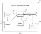
- FIG. 3 is a schematic diagram of another structure of the single-fiber bidirectional optical module 20 according to an embodiment of this application.
- the single-fiber bidirectional optical module 20 further includes an optical detector 205. It is assumed that before the wavelength of the first optical signal transmitted by the tunable light source 201 is adjusted and the target wavelength of the tunable filter 202 is adjusted, the target wavelength includes the wavelength of the first optical signal, therefore, the optical detector 205 is configured to detect the second optical signal L2 from the optical fiber port X.
- the controller 204 is configured to: when the optical detector 205 detects the optical signal and the receiver 203 detects no optical signal, determine that the target wavelength includes the wavelength of the second optical signal L2. It should be noted that, that an optical signal is detected means that an optical power of the detected optical signal is greater than an optical power threshold; and that no optical signal is detected means that the optical power of the detected optical signal is not greater than the optical power threshold. In this embodiment of this application, whether the target wavelength includes the wavelength of the second optical signal is detected by using the optical detector 205 and the receiver 203, to quickly identify whether the target wavelength matches the wavelength of the second optical signal.
- both the optical detector in the receiver 203 and the optical detector 205 may be a photodiode detector (Photodiode Detector, PD), an avalanche photodiode detector (Avalanche Photodiode Detector, APD), or another photoelectric conversion module.
- PD photodiode detector
- APD avalanche photodiode detector
- APD avalanche Photodiode Detector
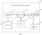
- FIG. 4 is a schematic diagram of another structure of the single-fiber bidirectional optical module 20 according to an embodiment of this application.
- the single-fiber bidirectional optical module 20 further includes an optical splitter 206 located between the tunable filter 202 and the optical fiber port X.
- the optical splitter 206 is configured to transmit one part of the second optical signal L2 from the optical fiber port X to the tunable filter 202, and transmit the other part to the optical detector 205.
- the optical detector 205 is configured to detect the optical signal transmitted by the optical splitter 206.
- the optical splitter is set, so that the one part of the second optical signal transmitted on a main path (namely, an optical path between the optical fiber port X and the tunable filter 202) is output to the optical detector 205 from a tributary path (namely, an optical path between the optical splitter 206 and the optical detector 205), to reduce impact on the second optical signal transmitted on the main path.
- the optical splitter 206 introduces the second optical signal into the tributary path for transmission at a specific optical splitting ratio, for example, the optical splitting ratio is less than or equal to 10%.
- the optical splitter 206 may be a coupler, a divider, a demultiplexer, or another optical splitting structure. Costs of manufacturing the demultiplexer are low, and costs can be effectively reduced by deploying the demultiplexer in the single-fiber bidirectional optical module. In FIG. 4 , an example in which the optical splitter 206 is the demultiplexer is used, but a specific structure of the optical splitter is not limited.
- the other single-fiber bidirectional optical module may execute a wavelength adjustment procedure at the same time.
- the wavelength adjustment procedures of the two single-fiber bidirectional optical modules are performed synchronously, for any single-fiber bidirectional optical module, if there are a large quantity of cases in which the adjusted target wavelength matches the wavelength of the second optical signal, the objective of wavelength adjustment cannot be quickly achieved.
- the controller 204 executes the at least two wavelength adjustment procedures, every two adjacent wavelength adjustment procedures is set are performed at an interval of target duration.
- the target duration is preset duration
- the target duration is different from target duration of the peer single-fiber bidirectional optical module (namely, a transmit end of the second optical signal)
- an interval of specified duration may be set between the two target duration.
- the target duration may be preset fixed duration, or may be preset variable duration.
- the variable duration is duration that changes according to a specific rule.
- the target duration is duration that increases by an equal proportion or an equal difference. It is assumed that the target duration is duration that increases by an equal difference of 0.5, therefore, a difference between an interval of duration between two wavelength adjustment procedures and a last interval of duration is 0.5, in other words, the controller gradually increases the interval of duration by 0.5, 1, 1.5, and the like.
- the target duration is random duration.
- execution moments of the wavelength adjustment procedures of the two single-fiber bidirectional optical modules are staggered, so that the wavelength adjustment procedures of the two single-fiber bidirectional optical modules are not executed synchronously. In this way, the quantity of times of performing the wavelength adjustment procedures of the two single-fiber bidirectional optical modules is reduced.
- the trigger condition is that the controller 204 determines that the optical fiber port does not input the second optical signal L2.
- the controller 204 is configured to: after determining that the optical fiber port does not input the second optical signal L2, adjust the wavelength of the first optical signal L1 transmitted by the tunable light source 201, and adjust the target wavelength of the tunable filter 202.
- the optical fiber port does not input the second optical signal
- the peer single-fiber bidirectional optical module may not be powered on; and on the other hand, the peer single-fiber bidirectional optical module may perform an invalid wavelength adjustment procedure. Therefore, the controller 204 may trigger execution of the wavelength adjustment procedure, and perform one or more wavelength adjustment procedures to wait for the peer single-fiber bidirectional optical module to test its transceiver function, thereby implementing successful wavelength negotiation with the peer single-fiber bidirectional optical module.
- the single-fiber bidirectional optical module can adjust the wavelength of the first optical signal transmitted by the tunable light source, and adjust the target wavelength of the tunable filter, so that the adjusted target wavelength includes the adjusted wavelength of the first optical signal and does not include the wavelength of the second optical signal.
- the tunable filter can transmit the first optical signal from the tunable light source to the optical fiber port, and transmit the second optical signal from the optical fiber port to the receiver, thereby ensuring the transceiver function of the single-fiber bidirectional optical module.
- the single-fiber bidirectional optical module When the single-fiber bidirectional optical module is deployed and maintained in the optical communication system, because the single-fiber bidirectional optical module can ensure its transceiver function, the wavelength of the optical signal of the single-fiber bidirectional optical module does not need to be preplanned and be manually configured. This effectively simplifies deployment and maintenance of the single-fiber bidirectional optical module, and improves deployment and maintenance efficiency.
- FIG. 5 is a schematic diagram of a structure of a communication apparatus 30 according to an embodiment of this application.
- the communication apparatus 30 may be a network device, for example, a router or a switch.
- the communication apparatus 30 includes any single-fiber bidirectional optical module 20 provided in the embodiments of this application, an electrical signal generation module 301, and an electrical signal processing module 302.
- the electrical signal generation module 301 is connected to the tunable light source 201, and the electrical signal generation module 301 is configured to input an electrical signal to the tunable light source 201.
- the electrical signal processing module 302 is connected to the receiver 203, the receiver 203 is further configured to output an electrical signal to the electrical signal processing module 302 based on a received optical signal, and the electrical signal processing module 302 is configured to process the received electrical signal.
- the electrical signal input by the electrical signal generation module 301 to the tunable light source 201 is generally different from the electrical signal received by the electrical signal processing module 302.
- the electrical signal generation module 301 includes a first processing module and a digital-to-analog conversion module.
- the first processing module is configured to receive an electrical signal output by a signal source, and output a digital signal based on the electrical signal.
- the digital-to-analog conversion module is configured to convert the digital signal output by the first processing module into an analog signal.
- the tunable light source 201 is configured to perform modulation on an optical signal based on the analog signal, to obtain the first optical signal.
- the digital-to-analog conversion module may be a digital-to-analog conversion (digital-to-analog conversion, DAC) chip or a parallel converter (serdes).
- the electrical signal processing module 302 includes an analog-to-digital conversion module and a second processing module.
- the receiver 203 is an optical-to-electrical conversion module, and may convert the second optical signal sent by the tunable filter 202 into an analog signal.
- the analog-to-digital conversion module is configured to convert the analog signal output by the receiver 203 into a digital signal.
- the second processing module is configured to obtain an electrical signal based on the digital signal output by the analog-to-digital conversion module.
- a process of converting an analog signal into a digital signal may include: performing analog-to-digital conversion (analog-to-digital conversion, ADC) sampling on a received analog signal to obtain a digital signal; or performing clock data recovery (clock data recovery, CDR) sampling on a received analog signal to obtain a digital signal.
- ADC analog-to-digital conversion
- CDR clock data recovery
- the electrical signal generation module 301 and the electrical signal processing module 302 may alternatively have other implementations.
- the foregoing embodiment is merely an example for description. This is not limited in this embodiment of this application.
- the communication apparatus 30 may perform communication based on a code division multiple access (Code Division Multiple Access, CDMA) technology, a frequency division multiple access (frequency division multiple access, FDMA) technology, or a time division multiple access (Time division multiple access, TDMA) technology.
- CDMA Code Division Multiple Access
- FDMA frequency division multiple access
- TDMA time division multiple access
- An embodiment of this application provides an optical communication system.
- the optical communication system includes two single-fiber bidirectional optical modules connected through an optical fiber.
- the two single-fiber bidirectional optical modules both include a single-fiber bidirectional optical module provided in the embodiments of this application, for example, the foregoing single-fiber bidirectional optical module.
- FIG. 6 is a schematic diagram of another structure of an optical communication system according to an embodiment of this application.
- an optical communication system 10 includes an optical fiber 101, and a first single-fiber bidirectional optical module 102 and a second single-fiber bidirectional optical module 103 that are connected through the optical fiber 101.
- the first single-fiber bidirectional optical module 102 includes an optical fiber port X1 for connecting to the optical fiber, a tunable light source 1021, a tunable filter 1022, a receiver 1023, and a controller 1024.
- the second single-fiber bidirectional optical module 103 includes an optical fiber port X2 for connecting to the optical fiber, a tunable light source 1031, a tunable filter 1032, a receiver 1033, and a controller 1034.
- the first single-fiber bidirectional optical module 102 and the second single-fiber bidirectional optical module 103 both can execute a wavelength adjustment procedure.
- FIG. 6 shows optical paths in the first single-fiber bidirectional optical module 102 and the second single-fiber bidirectional optical module 103 after the wavelength adjustment procedures are completed.
- a first optical signal transmitted by the first single-fiber bidirectional optical module 102 is a second optical signal received by the second single-fiber bidirectional optical module 103, and in FIG. 6 , it is assumed that a wavelength of the optical signal is ⁇ 1.
- a second optical signal received by the first single-fiber bidirectional optical module 102 is a first optical signal transmitted by the second single-fiber bidirectional optical module 103, and in FIG. 6 , it is assumed that a wavelength of the optical signal is ⁇ 2.
- FIG. 7 is a schematic diagram of still another structure of an optical communication system according to an embodiment of this application.
- the optical communication system 10 includes the optical fiber 101, and two communication apparatuses connected through the optical fiber 101.
- the two communication apparatuses both include the communication apparatus 30 described in the foregoing embodiment.
- the two communication apparatuses are respectively a first communication apparatus 30a and a second communication apparatus 30b, therefore, the first communication apparatus 30a includes an electrical signal generation module 301a, an electrical signal processing module 302a, and the first single-fiber bidirectional optical module 102.
- functions of the electrical signal generation module 301a and the electrical signal processing module 302a refer to functions of the electrical signal generation module 301 and the electrical signal processing module 302 shown in FIG. 5 .
- the second communication apparatus 30b includes an electrical signal generation module 301b, an electrical signal processing module 302b, and the second single-fiber bidirectional optical module 103.
- functions of the electrical signal generation module 301b and the electrical signal processing module 302b refer to the functions of the electrical signal generation module 301 and the electrical signal processing module 302 shown in FIG. 5 .
- functions of the second single-fiber bidirectional optical module 102 refer to a function of the second single-fiber bidirectional optical module 103 shown in FIG. 6 .
- a plurality of groups of target wavelengths supported by tunable filters of the first single-fiber bidirectional optical module 102 and the second single-fiber bidirectional optical module 103 are correspondingly the same.
- a plurality of wavelengths supported by tunable light sources of the first single-fiber bidirectional optical module 102 and the second single-fiber bidirectional optical module 103 are in a one-to-one correspondence. Such setting can implement fast wavelength negotiation.
- the plurality of groups of target wavelengths supported by the tunable filters may be uniformly configured. Costs of setting the wavelengths for the single-fiber bidirectional optical modules are reduced.
- the plurality of wavelengths supported by the tunable light sources of the first single-fiber bidirectional optical module 102 and the second single-fiber bidirectional optical module 103 are also correspondingly the same.
- the plurality of groups of target wavelengths supported by the tunable filters and the plurality of wavelengths supported by the tunable light sources may be uniformly configured. Costs of setting the wavelengths for the single-fiber bidirectional optical modules are reduced.
- each single-fiber bidirectional optical module may support two wavelengths, and correspondingly, the tunable filter of each single-fiber bidirectional optical module supports two groups of target wavelengths. In this way, on a premise that the single-fiber bidirectional optical module can execute the wavelength adjustment procedure, a probability of successfully performing highly-efficient wavelength negotiation is effectively improved.
- FIG. 8 is a schematic flowchart of an optical communication method according to an embodiment of this application. Any single-fiber bidirectional optical module in an optical communication system can perform the method.
- the method includes: S401: Transmit, by using a tunable light source, a first optical signal to a tunable filter.
- the single-fiber bidirectional optical module When the single-fiber bidirectional optical module needs to communicate with a peer single-fiber bidirectional optical module, the single-fiber bidirectional optical module transmits the first optical signal to the tunable filter by using the tunable light source. For example, after being powered on, the single-fiber bidirectional optical module may transmit the first optical signal to the tunable filter by using the tunable light source.
- the tunable light source For a working process of the tunable light source, refer to a corresponding working process in the foregoing embodiments of the single-fiber bidirectional optical module. Details are not described herein in this embodiment of this application.
- S402 Transmit, by using the tunable filter, an optical signal of a target wavelength in the first optical signal from the tunable light source to an optical fiber port of the single-fiber bidirectional optical module, and transmit an optical signal of a wavelength other than the target wavelength in a second optical signal from the optical fiber port to a receiver.
- S403 Receive, by using the receiver, the optical signal transmitted by the tunable filter.
- S404 Adjust the wavelength of the first optical signal transmitted by the tunable light source, and adjust the target wavelength of the tunable filter, so that an adjusted target wavelength includes an adjusted wavelength of the first optical signal and does not include a wavelength of the second optical signal.
- a wavelength adjustment procedure may have a plurality of trigger mechanisms.
- the following four trigger mechanisms are used as examples for description:
- a trigger condition is that a wavelength adjustment instruction is received.
- the wavelength of the first optical signal transmitted by the tunable light source is adjusted, and the target wavelength of the tunable filter is adjusted.
- the trigger condition is that the target wavelength does not include the wavelength of the first optical signal.
- the wavelength of the first optical signal transmitted by the tunable light source is adjusted, and the target wavelength of the tunable filter is adjusted.
- the trigger condition is that the target wavelength includes the wavelength of the second optical signal.
- the wavelength of the first optical signal transmitted by the tunable light source is adjusted, and the target wavelength of the tunable filter is adjusted.
- the trigger condition is that the optical fiber port does not input the second optical signal.
- the wavelength of the first optical signal transmitted by the tunable light source is adjusted, and the target wavelength of the tunable filter is adjusted.
- the single-fiber bidirectional optical module may detect, in a plurality of manners, whether the target wavelength includes the wavelength of the second optical signal. For example, the single-fiber bidirectional optical module may determine, by detecting whether both the optical fiber port and the receiver have optical signal input, whether the target wavelength includes the wavelength of the second optical signal. Refer to FIG. 3 .
- the single-fiber bidirectional optical module may further detect the second optical signal from the optical fiber port by using an optical detector. When the optical detector detects the second optical signal from the optical fiber port, and the receiver detects no optical signal, the single-fiber bidirectional optical module determines that the target wavelength includes the wavelength of the second optical signal.
- a process of detecting, by using the optical detector, the second optical signal from the optical fiber port includes: transmitting, by using an optical splitter, one part of the second optical signal from the optical fiber port to the tunable filter, and transmitting the other part to the optical detector; and detecting, by the optical detector, the optical signal transmitted by the optical splitter.
- the optical splitter is set, so that the one part of the second optical signal transmitted on a main path is output to the optical detector from a tributary path, to reduce impact on the second optical signal transmitted on the main path.
- the foregoing process of adjusting the wavelength of the first optical signal transmitted by the tunable light source, and adjusting the target wavelength of the tunable filter, so that the adjusted target wavelength includes the adjusted wavelength of the first optical signal and does not include the wavelength of the second optical signal may include: performing one or more wavelength adjustment procedures until the adjusted target wavelength includes the adjusted wavelength of the first optical signal and does not include the wavelength of the second optical signal.
- the wavelength adjustment procedure includes: adjusting the wavelength of the first optical signal transmitted by the tunable light source, and adjusting the target wavelength of the tunable filter.
- At least two wavelength adjustment procedures may be performed until the adjusted target wavelength includes the adjusted wavelength of the first optical signal and does not include the wavelength of the second optical signal.
- every two adjacent wavelength adjustment procedures are performed at an interval of target duration.
- the target duration is preset duration
- the target duration is different from target duration of a peer single-fiber bidirectional optical module, and an interval of specified duration may be set between the two target duration.
- the target duration may be preset fixed duration, or may be preset variable duration.
- the target duration is random duration.
- execution moments of wavelength adjustment procedures of two single-fiber bidirectional optical modules are staggered, so that the wavelength adjustment procedures of the two single-fiber bidirectional optical modules are not executed synchronously. In this way, a quantity of times of performing the wavelength adjustment procedures of the two single-fiber bidirectional optical modules is reduced.
- a change amount of the adjusted target wavelength relative to the target wavelength before adjustment is less than 10 nanometers, therefore, a narrow adjustment process of the target wavelength can be implemented; and a change amount of the adjusted wavelength of the first optical signal relative to the wavelength of the first optical signal before adjustment is less than 10 nanometers, therefore, a narrow adjustment process of the wavelength of the first optical signal can be implemented.
- One wavelength adjustment procedure may be completed in a short time period by executing the narrow adjustment process of the first optical signal and the narrow adjustment process of the target wavelength, thereby reducing a delay in completing a wavelength negotiation process.
- the corresponding adjustment process refer to the foregoing corresponding process of the single-fiber bidirectional optical module.
- FIG. 9 is a schematic flowchart of a wavelength negotiation process according to an embodiment of this application.
- FIG. 9 schematically describes S404 in the optical communication method with reference to FIG. 4 .
- S404 includes the following steps:
- the single-fiber bidirectional optical module can adjust the wavelength of the first optical signal transmitted by the tunable light source, and adjust the target wavelength of the tunable filter, so that the adjusted target wavelength includes the adjusted wavelength of the first optical signal and does not include the wavelength of the second optical signal.
- the tunable filter can transmit the first optical signal from the tunable light source to the optical fiber port, and transmit the second optical signal from the optical fiber port to the receiver, thereby ensuring a transceiver function of the single-fiber bidirectional optical module.
- the single-fiber bidirectional optical module When the single-fiber bidirectional optical module is deployed and maintained in the optical communication system, because the single-fiber bidirectional optical module can ensure its transceiver function, a wavelength of an optical signal of the single-fiber bidirectional optical module does not need to be preplanned and be manually configured. This effectively simplifies deployment and maintenance of the single-fiber bidirectional optical module, and improves deployment and maintenance efficiency.
- a non-transitory computer-readable storage medium including instructions is further provided, for example, a memory including instructions.
- the foregoing instructions may be executed by a processor of a communication apparatus to complete the optical communication method shown in the embodiments of this application.
- the non-transitory computer-readable storage medium may be a read-only memory (Read-Only Memory, ROM), a random access memory (Random Access Memory, RAM), a compact disc read-only memory (Compact Disc Read-Only Memory, CD-ROM), a tape, a floppy disk, or an optical data storage device.
- the single-fiber bidirectional optical module provided in the foregoing embodiments executes the optical communication method
- division into the foregoing functional modules is merely used as an example for description.
- the foregoing functions may be allocated to different functional modules for implementation based on a requirement.
- an internal structure of the single-fiber bidirectional optical module is divided into different functional modules to implement all or part of functions described above.
- the single-fiber bidirectional optical module and the optical communication system provided in the foregoing embodiments belong to a same concept as the optical communication method embodiments. For a specific implementation process thereof, refer to the method embodiment. Details are not described herein again.
- the program may be stored in a computer-readable storage medium.
- the storage medium may include: a read-only memory, a magnetic disk, or an optical disc.
Landscapes
- Physics & Mathematics (AREA)
- Electromagnetism (AREA)
- Engineering & Computer Science (AREA)
- Computer Networks & Wireless Communication (AREA)
- Signal Processing (AREA)
- Optical Communication System (AREA)
Applications Claiming Priority (1)
| Application Number | Priority Date | Filing Date | Title |
|---|---|---|---|
| CN202110333424.XA CN115133993A (zh) | 2021-03-29 | 2021-03-29 | 单纤双向光模块、通信装置、光通信系统及通信方法 |
Publications (2)
| Publication Number | Publication Date |
|---|---|
| EP4068655A2 true EP4068655A2 (fr) | 2022-10-05 |
| EP4068655A3 EP4068655A3 (fr) | 2022-10-19 |
Family
ID=80930186
Family Applications (1)
| Application Number | Title | Priority Date | Filing Date |
|---|---|---|---|
| EP22163467.8A Withdrawn EP4068655A3 (fr) | 2021-03-29 | 2022-03-22 | Module optique bidirectionnel à fibre unique, appareil de communication, système de communication optique et procédé de communication |
Country Status (3)
| Country | Link |
|---|---|
| US (1) | US20220321231A1 (fr) |
| EP (1) | EP4068655A3 (fr) |
| CN (1) | CN115133993A (fr) |
Families Citing this family (3)
| Publication number | Priority date | Publication date | Assignee | Title |
|---|---|---|---|---|
| CN115664513B (zh) * | 2022-10-25 | 2026-04-21 | 深圳市威湃创新科技有限公司 | 一种可支持多波长光源系统的双向可调光衰减方法 |
| CN119676593A (zh) * | 2023-09-20 | 2025-03-21 | 华为技术有限公司 | 一种波长切换方法、网络节点及系统 |
| CN118884631B (zh) * | 2024-08-12 | 2025-04-01 | 珠海奇芯光电科技有限公司 | 一种单纤双向光模块 |
Family Cites Families (6)
| Publication number | Priority date | Publication date | Assignee | Title |
|---|---|---|---|---|
| JP4602900B2 (ja) * | 2005-09-09 | 2010-12-22 | 日本電信電話株式会社 | 一心双方向の波長多重光通信システムにおける光送受信装置 |
| WO2010064981A1 (fr) * | 2008-12-01 | 2010-06-10 | Telefonaktiebolaget L M Ericsson (Publ) | Procédés et dispositifs d’alignement de longueur d’onde dans les pon wdm |
| EP2573966B1 (fr) * | 2011-07-20 | 2013-11-13 | ADVA Optical Networking SE | Procédé de blocage de longueur d'onde pour un dispositif émetteur-récepteur optique et dispositif émetteur-récepteur optique |
| US9287984B2 (en) * | 2011-12-21 | 2016-03-15 | Skorpios Technologies, Inc. | Tunable bi-directional transceiver |
| CN108333691A (zh) * | 2017-01-20 | 2018-07-27 | 山东华云光电技术有限公司 | 一种波长可调单纤双向光发射接收组件 |
| CN109672475B (zh) * | 2019-01-09 | 2024-08-09 | 杭州芯耘光电科技有限公司 | 一种可远程调节波长的双向传输光模块 |
-
2021
- 2021-03-29 CN CN202110333424.XA patent/CN115133993A/zh active Pending
-
2022
- 2022-03-22 EP EP22163467.8A patent/EP4068655A3/fr not_active Withdrawn
- 2022-03-29 US US17/707,631 patent/US20220321231A1/en not_active Abandoned
Also Published As
| Publication number | Publication date |
|---|---|
| US20220321231A1 (en) | 2022-10-06 |
| EP4068655A3 (fr) | 2022-10-19 |
| CN115133993A (zh) | 2022-09-30 |
Similar Documents
| Publication | Publication Date | Title |
|---|---|---|
| EP4068655A2 (fr) | Module optique bidirectionnel à fibre unique, appareil de communication, système de communication optique et procédé de communication | |
| US11108488B2 (en) | Optical transceiver and method of controlling optical powers of optical channels | |
| US7123833B2 (en) | Dynamically reconfigurable optical smart node | |
| CN114124287B (zh) | 光信号控制方法及装置、光传输节点和光传输系统 | |
| RU2101867C1 (ru) | Система асинхронной временной оптической связи | |
| JPH07221738A (ja) | 光通信網におけるパケット転送交換のための方法および装置 | |
| EP3160094A1 (fr) | Noeud de routage, réseau de commutation optique et procédé d'émission de signal optique | |
| US9112610B2 (en) | Optical network unit registration method | |
| EP3730981B1 (fr) | Procédé et dispositif d'étalonnage de longueur d'onde d'un filtre à microanneau | |
| JP5556921B1 (ja) | 加入者側装置登録方法及び光ネットワークシステム | |
| US20220271858A1 (en) | Wavelength switching and configuration method and device for passive optical network | |
| US20240291569A1 (en) | Optical signal receiving apparatus, system and method, optical line terminal, and computer-readable storage medium | |
| EP4106234A1 (fr) | Commutateur optique et procédé de test de performance optique basé sur un commutateur optique | |
| CN101057424B (zh) | 一种dwdm系统中波长集中监控的装置及方法 | |
| JP2004501346A (ja) | Wdmシステム用の波長モニタ | |
| EP3001590B1 (fr) | Procédé et appareil de communication optique | |
| CN110086538B (zh) | 同波长光模块波长配对的自协商模块、网络系统及方法 | |
| US20240283545A1 (en) | Optical signal receiving apparatus, method and system, optical line terminal, computer-readable storage medium | |
| JP2655445B2 (ja) | ループ型光ローカルエリアネットワークシステムにおけるアクセス制御方式およびそのノード装置 | |
| CN114978324A (zh) | 光通信装置的波长自动设定系统 | |
| US12615085B2 (en) | Optical signal control method and apparatus, optical transmission node, and optical transmission system | |
| CN112578504A (zh) | 一种mems光开关自动扫描装置及其方法 | |
| EP2479906A1 (fr) | Procédé de fonctionnement d'une ligne de transmission optique, système de transmission optique, transmetteur optique et récepteur optique | |
| CN104539354A (zh) | 基于光模块眼图测试的信号提取装置及提取方法 | |
| CN109818740B (zh) | 一种使用波分复用器的上行连续变量量子密钥分发接入网方法 |
Legal Events
| Date | Code | Title | Description |
|---|---|---|---|
| PUAI | Public reference made under article 153(3) epc to a published international application that has entered the european phase |
Free format text: ORIGINAL CODE: 0009012 |
|
| STAA | Information on the status of an ep patent application or granted ep patent |
Free format text: STATUS: REQUEST FOR EXAMINATION WAS MADE |
|
| PUAL | Search report despatched |
Free format text: ORIGINAL CODE: 0009013 |
|
| 17P | Request for examination filed |
Effective date: 20220322 |
|
| AK | Designated contracting states |
Kind code of ref document: A2 Designated state(s): AL AT BE BG CH CY CZ DE DK EE ES FI FR GB GR HR HU IE IS IT LI LT LU LV MC MK MT NL NO PL PT RO RS SE SI SK SM TR |
|
| AK | Designated contracting states |
Kind code of ref document: A3 Designated state(s): AL AT BE BG CH CY CZ DE DK EE ES FI FR GB GR HR HU IE IS IT LI LT LU LV MC MK MT NL NO PL PT RO RS SE SI SK SM TR |
|
| RIC1 | Information provided on ipc code assigned before grant |
Ipc: H04B 10/572 20130101ALI20220912BHEP Ipc: H04B 10/25 20130101AFI20220912BHEP |
|
| STAA | Information on the status of an ep patent application or granted ep patent |
Free format text: STATUS: THE APPLICATION IS DEEMED TO BE WITHDRAWN |
|
| 18D | Application deemed to be withdrawn |
Effective date: 20241001 |