EP4067949A1 - Mirror - Google Patents
Mirror Download PDFInfo
- Publication number
- EP4067949A1 EP4067949A1 EP20894783.8A EP20894783A EP4067949A1 EP 4067949 A1 EP4067949 A1 EP 4067949A1 EP 20894783 A EP20894783 A EP 20894783A EP 4067949 A1 EP4067949 A1 EP 4067949A1
- Authority
- EP
- European Patent Office
- Prior art keywords
- mirror
- rib
- body portion
- shape
- outer peripheral
- Prior art date
- Legal status (The legal status is an assumption and is not a legal conclusion. Google has not performed a legal analysis and makes no representation as to the accuracy of the status listed.)
- Granted
Links
Images










Classifications
-
- G—PHYSICS
- G02—OPTICS
- G02B—OPTICAL ELEMENTS, SYSTEMS OR APPARATUS
- G02B5/00—Optical elements other than lenses
- G02B5/08—Mirrors
- G02B5/10—Mirrors with curved faces
-
- G—PHYSICS
- G02—OPTICS
- G02B—OPTICAL ELEMENTS, SYSTEMS OR APPARATUS
- G02B7/00—Mountings, adjusting means, or light-tight connections, for optical elements
- G02B7/18—Mountings, adjusting means, or light-tight connections, for optical elements for prisms; for mirrors
-
- G—PHYSICS
- G02—OPTICS
- G02B—OPTICAL ELEMENTS, SYSTEMS OR APPARATUS
- G02B23/00—Telescopes, e.g. binoculars; Periscopes; Instruments for viewing the inside of hollow bodies; Viewfinders; Optical aiming or sighting devices
- G02B23/02—Telescopes, e.g. binoculars; Periscopes; Instruments for viewing the inside of hollow bodies; Viewfinders; Optical aiming or sighting devices involving prisms or mirrors
Definitions
- An embodiment of the present disclosure relates to a mirror.
- An astronomical telescope or the like is provided with a mirror for reflecting light from an observation target.
- a mirror for an astronomical telescope including a mirror member having a reflecting surface for reflecting light and made of low thermal expansion ceramics and a reflecting film provided on the reflecting surface of such a mirror member is disclosed (see PTL 1).
- a mirror according to an aspect of an embodiment includes a mirror surface provided on a front surface of a body portion, having a plate shape and made of ceramics, a recessed portion formed on a back surface of the body portion, and a rib provided along an edge of the recessed portion and including a tapered side surface.
- An astronomical telescope or the like is provided with a mirror for reflecting light from an observation target.
- a mirror for an astronomical telescope including a mirror member having a reflecting surface for reflecting light and made of low thermal expansion ceramics and a reflecting film provided on the reflecting surface of such a mirror member is disclosed.
- a core member for reinforcing the mirror member is separately required, in a manufacturing process of a mirror, a step of manufacturing the core member, a step of bonding the mirror member and the core member, and the like are separately required. That is, in the related art, it is difficult to easily manufacture the mirror.
- FIG. 1 is a plan view of the mirror 1 according to the embodiment when viewed from a front surface 3 side
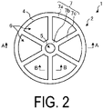
- FIG. 2 is a plan view of the mirror 1 according to the embodiment when viewed from a back surface 4 side
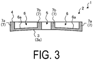
- FIG. 3 is a cross-sectional view taken along line A-A in a direction of arrows in FIG. 2 .
- a device including the mirror 1 according to the embodiment applied thereto is not limited to the astronomical telescope.
- the mirror 1 includes a plate-shaped (disk-shaped in the present disclosure) body portion 2 made of ceramics. Such a body portion 2 is provided with a front surface 3 and a back surface 4.
- the front surface 3 has a curved (for example, spherical) mirror surface 3a on the entire surface thereof.
- the mirror surface 3a is formed by, for example, mirror-polishing the front surface 3 entirely and then applying a coating that reflects light to such a mirror surface.
- the mirror 1 according to the embodiment can reflect light from an observation target on the mirror surface 3a.
- the present disclosure describes a case where the mirror surface 3a has a recessed shape, but the shape of the mirror surface 3a is not limited to the recessed shape and may be a planar shape or a convex shape. Furthermore, the mirror surface 3a is not limited to a spherical surface, and may be an aspherical surface.
- the body portion 2 is formed in the center portion thereof with a cylindrical through hole 5 that penetrates from the front surface 3 to the back surface 4.
- a through hole 5 that penetrates from the front surface 3 to the back surface 4.
- a plurality of recessed portions 6 are formed on the back surface 4 of the body portion 2.
- a recessed portion 6 has, for example, a fan shape having a center angle of about 60°in the plan view.
- six recessed portions 6 are equally disposed along the circumferential direction of the disk-shaped body portion 2.
- a rib 7 is provided on the back surface 4 of the body portion 2 along edges of such recessed portions 6. As illustrated in FIG. 3 , the rib 7 is provided to rise substantially perpendicular from the bottom surfaces 6a of the recessed portions 6 toward the back surface 4.
- the rib 7 includes an outer peripheral rib 7a provided on an outer peripheral side of the back surface 4, an inner peripheral rib 7b provided on an inner peripheral side of the back surface 4, and a connection rib 7c provided to connect the outer peripheral rib 7a and the inner peripheral rib 7b.
- the outer peripheral rib 7a is provided along an outer edge portion of the back surface 4, for example.
- the inner peripheral rib 7b is provided between the through hole 5 and the recessed portions 6 to surround the through hole 5, for example.
- the connection rib 7c is provided radially from a center portion of the back surface 4 toward the outer edge portion of the back surface 4, for example.
- the volume of the mirror 1 can be reduced, so that the mirror 1 can be reduced in weight.
- the rib 7 is formed along the edges of the recessed portions 6, so that the strength of the mirror 1 reduced in weight by the recessed portion 6 can be ensured.
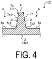
- FIG. 4 is a cross-sectional view taken along line B-B in a direction of arrows in FIG. 2 , and is an enlarged cross-sectional view illustrating the configuration of the connection rib 7c according to the embodiment.
- connection rib 7c has tapered side surfaces 7c1.
- Such a side surface 7c1 is inclined with respect to the back surface 4 so that an inlet side of a recessed portion 6 in contact with the side surface 7c1 is widened.
- An inclination angle ⁇ of the side surface 7c1 is in the range of, for example, 1° to 5°, and is preferably in the range of 2° to 3°.
- connection rib 7c has the tapered side surfaces 7c1, so that a molded article to be fired later to become the body portion 2 is molded with a mold, and then such a mold can be easily removed from the molded article in the manufacturing process of the mirror 1.
- the molded article to be the body portion 2 can be easily molded with the mold, so that the mirror 1 can be easily manufactured. Furthermore, in the embodiment, a distal end side of the connection rib 7c can be thinned, so that the mirror 1 can be reduced in weight.
- a corner portion 7c2 located at a lower end of the connection rib 7c has an R shape.
- Such a corner portion 7c2 is a portion where the side surface 7c1 of the connection rib 7c and the bottom surface 6a of the recessed portion 6 are in contact with each other.
- connection rib 7c since the corner portion 7c2 of the connection rib 7c has an R shape, stress can be suppressed from being concentrated on such a corner portion 7c2, so that the strength in the vicinity of the connection rib 7c in the body portion 2 can be improved.
- the side surfaces 7c1 on both sides of the connection ribs 7c may be tapered together. Accordingly, after the molded article to be the body portion 2 is molded with the mold, such a mold can be more easily removed from the molded article.
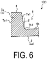
- FIG. 5 is an enlarged cross-sectional view illustrating the configuration of the outer peripheral rib 7a according to the embodiment.
- the outer peripheral rib 7a according to the embodiment has tapered side surfaces 7a1.
- a side surface 7a1 in contact with the recessed portion 6 is inclined with respect to the back surface 4 so that the inlet side of such a recessed portion 6 is widened.
- a side surface 7a1 to be the side surface of the body portion 2 on the outer peripheral side is inclined with respect to the back surface 4 so that the back surface 4 side is closer to the center of the body portion 2 than the front surface 3 side.
- An inclination angle ⁇ of the side surface 7a1 is in the range of, for example, 1° to 5°, and is preferably in the range of 2° to 3°.
- the outer peripheral rib 7a has the tapered side surface 7a1, so that the molded article to be fired later to become the body portion 2 is molded with the mold, and then such a mold can be easily removed from the molded article in the manufacturing process of the mirror 1.
- the molded article to be the body portion 2 can be easily molded with the mold, so that the mirror 1 can be easily manufactured. Furthermore, in the embodiment, a distal end side of the outer peripheral rib 7a can be thinned, so that the mirror 1 can be reduced in weight.
- the corner portion 7a2 located at a lower end of the outer peripheral rib 7a has an R shape.
- Such a corner portion 7a2 is a portion where the side surface 7a1 of the outer peripheral rib 7a and the bottom surface 6a of the recessed portion 6 are in contact with each other.
- corner portion 7a2 of the outer peripheral rib 7a has an R shape, stress can be suppressed from being concentrated on the corner portion 7a2, so that the strength in the vicinity of the outer peripheral rib 7a in the body portion 2 can be improved.
- FIG. 6 is an enlarged cross-sectional view illustrating another configuration of the outer peripheral rib 7a according to the embodiment.
- the mold in contact with the side surface 7a1 can be pulled out to the outer peripheral side of the molded article, so that the mold can be pulled out without any particular problem.
- FIG. 7 is an enlarged cross-sectional view illustrating the configuration of the inner peripheral rib 7b according to the embodiment.
- such an inner peripheral rib 7b according to the embodiment has tapered side surfaces 7b1.
- a side surface 7b1 in contact with the recessed portion 6 is inclined with respect to the back surface 4 so that the inlet side of such a recessed portion 6 is widened.
- An inclination angle ⁇ of such a side surface 7b1 is in the range of, for example, 1° to 5°, and is preferably is in the range of 2° to 3°.
- the inner peripheral rib 7b has the tapered side surfaces 7b1, so that the molded article to be fired later to become the body portion 2 is molded with the mold, and then the mold can be easily removed from the molded article, in the manufacturing process of the mirror 1.
- the molded article to be the body portion 2 can be easily molded with the mold, so that the mirror 1 can be easily manufactured. Furthermore, in the embodiment, a distal end side of the inner peripheral rib 7b can be thinned, so that the mirror 1 can be reduced in weight.
- a side surface 7b1 in contact with the recessed portion 6 is preferably tapered. In this way, even when a side surface 7b1 in contact with the through hole 5 is formed substantially perpendicular to the back surface 4, the mold in contact with such a side surface 7b1 is pulled out along the axial direction of the through hole, so that the mold can be pulled out without any particular problem.
- the corner portion 7b2 located at a lower end of the inner peripheral rib 7b has an R shape.
- Such a corner portion 7b2 is a portion where the side surface 7b1 of the inner peripheral rib 7b and the bottom surface 6a of the recessed portion 6 are in contact with each other.
- corner portion 7b2 of the inner peripheral rib 7b has an R shape, stress can be suppressed from being concentrated on such a corner portion 7b2, so that the strength in the vicinity of the inner peripheral rib 7b in the body portion 2 can be improved.
- a width of the outer peripheral rib 7a is preferably wider than that of the inner peripheral rib 7b and that of the connection rib 7c. This can further improve the strength of the mirror 1.
- FIG. 8 is an enlarged cross-sectional view illustrating the configuration of the bottom surface 6a of the recessed portion 6 according to the embodiment.
- the bottom surface 6a of the recessed portion 6 is preferably a curved surface along the shape of the mirror surface 3a. In this way, the mirror 1 can be reduced in weight by making a wall thickness between the mirror surface 3a and the bottom surface 6a constant.
- the bottom surface 6a of the recessed portion 6 according to the embodiment is not limited to the curved surface along the shape of the mirror surface 3a.
- FIG. 9 is an enlarged cross-sectional view illustrating another configuration of the bottom surface 6a of the recessed portion 6 according to the embodiment.
- the bottom surface 6a of the recessed portion 6 may in a stepped shape along the shape of the mirror surface 3a.
- the mold can be easily formed as compared with a case where the bottom surface 6a includes many curved surfaces, so that the manufacturing cost of the mirror 1 can be reduced.
- FIG. 9 illustrates an example in which a stepped portion that connects the flat surfaces of the bottom surface 6a has a taper, but since such a stepped portion has a small step difference of about 1 mm, it does not necessarily have to have a taper.
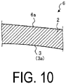
- FIG. 10 is an enlarged cross-sectional view illustrating another configuration of the bottom surface 6a of the recessed portion 6 according to the embodiment.
- the bottom surface 6a of the recessed portion 6 according to the embodiment may be a flat surface along the shape of the mirror surface 3a.
- the mold can be easily formed as compared with the case where the bottom surface 6a includes many curved surfaces, so that the manufacturing cost of the mirror 1 can be reduced. Furthermore, in the example of FIG. 10 , the wall thickness between the mirror surface 3a and the bottom surface 6a can be made as thin as possible, so that the mirror 1 can be further reduced in weight.
- FIG. 11 is a plan view illustrating another configuration of the body portion 2 according to the embodiment.
- the body portion 2 may have a flat portion 8 on a part of the side surface on the outer peripheral side thereof.
- the flat portion 8 is provided to a part of the side surface in the body portion 2, so that positioning can be facilitated in the process of processing the body portion 2.
- the dimensional accuracy of the body portion 2 can be improved. Furthermore, the flat portion 8 is provided to a part of the side surface in the body portion 2, so that positioning can be facilitated when the mirror 1 is installed in an astronomical telescope.
- ceramics constituting the body portion 2 for example, cordierite ceramics, aluminum oxide ceramics, zirconium oxide ceramics, silicon nitride ceramics, aluminum nitride ceramics, silicon carbide ceramics, mullite ceramics, and the like can be used.
- the body portion 2 is made of ceramics, so that the mirror 1 having high mechanical strength and excellent heat resistance can be implemented.
- the body portion 2 is made of cordierite ceramics having a low specific gravity and a low thermal expansion rate, so that the mirror 1 can be reduced in weight and reliability can be improved under an environment where the temperature changes drastically.
- the cordierite ceramics contains 80 mass% of cordierite (2MgO ⁇ 2Al 2 O 3 ⁇ 5SiO 2 ) out of 100 mass% of all components constituting the ceramics.
- XRD X-ray diffraction
- the material of the body portion 2 can be regarded as cordierite ceramics.
- synthetic cordierite powder which is obtained by calcining and synthesizing mixed powder obtained by blending magnesium carbonate powder, aluminum oxide powder, and silicon oxide powder at a predetermined ratio, is prepared.
- the obtained synthetic cordierite powder and sintering aid powder are weighed at a predetermined ratio and used as primary raw materials.
- the obtained primary raw material powders are wet-mixed, and then a predetermined amount of binder is added to obtain a slurry.
- the obtained slurry is poured into a mold processed into a predetermined shape in advance, is dried at a predetermined temperature and time to be solidified, and then is molded by a cast molding method or the like for demolding. Moreover, machine-cutting and the like are performed to obtain a molded article having any shape.
- the obtained molded article is fired in a firing furnace at a maximum temperature of 1,300°C or higher and 1,450°C or less in an air atmosphere, so that a fired body is obtained. Thereafter, grinding, polishing, coating, and the like are performed on the fired body as necessary, so that the body portion 2 according to the embodiment can be obtained.
- FIG. 12 is a plan view of a mirror 1 according to the first modification of the embodiment when viewed from the front surface 3 side
- FIG. 13 is a plan view of the mirror 1 according to the first modification of the embodiment when viewed from the back surface 4 side
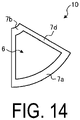
- FIG. 14 is a plan view of a split member 10 according to the first modification of the embodiment when viewed from the back surface 4 side.
- the mirror 1 according to the first modification is different from the embodiment in that an overall shape is the same as that of the mirror 1 according to the embodiment, but a plurality of split members 10 having the same shape are connected to configure the body portion 2.
- split members 10 having a fan shape with a central angle of 60° in the plan view can be connected to configure the body portion 2 of the first modification.
- the body portion 2 is configured by connecting the plurality of split members 10 having the same shape, so that the mirror 1 can be easily increased in size. Furthermore, since the body portion 2 is configured by connecting the plurality of split members 10 having the same shape, even when a part of the mirror 1 is damaged, only the damaged portion can be replaced.
- the recessed portion 6 is formed in the center portion of such a split member 10, and the outer peripheral rib 7a, the inner peripheral rib 7b, and a partial rib 7d (corresponding to a part of the connection rib 7c) are formed along the edge of the recessed portion 6, so that the mirror 1 having the configuration shown in the aforementioned embodiment can be implemented.
- FIG. 15 is a cross-sectional view taken along line C-C in a direction of arrows in FIG. 13 , and is an enlarged cross-sectional view illustrating the configuration of the connection rib 7c according to the first modification.
- the connection rib 7c according to the first modification is configured by connecting the partial ribs 7d of the split members 10.
- connection rib 7c according to the first modification has the tapered side surface 7c1 as in the aforementioned embodiment. Since the configurations of the outer peripheral rib 7a and the inner peripheral rib 7b in the mirror 1 of first modification are the same as those of the aforementioned embodiment, description thereof will be omitted.
- connection rib 7c has the tapered side surface 7c1, so that a molded article to be fired later to become the split member 10 is molded with a mold, and then the mold can be easily removed from the molded article in the manufacturing process of the mirror 1.
- the molded article to be the split member 10 can be easily molded with the mold, so that the mirror 1 can be easily manufactured. Furthermore, in the first modification, a distal end side of the connection rib 7c can be thinned, so that the mirror 1 can be reduced in weight.
- the plurality of split members 10 can be connected by adhering contact surfaces, where the split members 10 are in contact with each other, by a bonding material or the like.
- FIG. 16 is an enlarged cross-sectional view illustrating another configuration of the connection rib 7c according to the first modification of the embodiment.
- a flat surface substantially perpendicular to the axial direction of the through hole is formed around the through hole 5 on the side surface 7c1 of the partial rib 7d.
- the arithmetic average roughness Ra of the contact surface, where the split members 10 are in contact with each other is 0.8 ⁇ m or less and the flatness per unit length is 5 ⁇ m or less. Accordingly, a contact between adjacent split members 10 is good, so that a gap between the front surfaces 3 of the adjacent split members 10 can be reduced.
- the surface accuracy of the mirror surface 3a configured by a set of the front surfaces 3 of the split members 10 can be improved.
- FIG. 17 is a perspective view illustrating another configuration of the body portion 2 according to the first modification of the embodiment.
- adjacent split members 10 may be connected via a plate-shaped member 21 disposed to cover the partial rib 7d.
- a plurality of through holes 21a are formed in such a plate-shaped member 21, and screw holes 7d1 are formed on a surface of the partial rib 7d on the back face 4 side at positions corresponding to such through holes 21a.
- the plate-shaped member 21 is disposed to cover adjacent partial ribs 7d, and bolts 22 are screwed into the through holes 21a and the screw holes 7d1, so that the adjacent split members 10 can be connected via the plate-shaped member 21.
- FIG. 17 illustrates an example in which the plurality of split members 10 are connected by using the plate-shaped member 21 and the fastening members 20, but the plurality of split members 10 may be connected by using only the plate-shaped member 21 without using the fastening members 20.
- FIG. 18 is a plan view illustrating another configuration of the body portion 2 according to the first modification of the embodiment.
- the body portion 2 of the first modification may have a flat portion 8 on a part of the side surface on the outer peripheral side thereof.
- the flat portion 8 is provided to a part of the side surface in the body portion 2, so that positioning can be facilitated in the process of processing the body portion 2.
- the dimensional accuracy of the body portion 2 can be improved. Furthermore, the flat portion 8 is provided to a part of the side surface in the body portion 2, so that positioning can be facilitated when the mirror 1 is installed in an astronomical telescope.
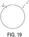
- FIG. 19 is a plan view of the mirror 1 according to the second modification of the embodiment when viewed from the front side 3 side
- FIG. 20 is a plan view of the mirror 1 according to the second modification of the embodiment when viewed from the back surface 4 side
- FIG. 21 is a cross-sectional view taken along the line D-D in a direction of arrows in FIG. 20 .
- the mirror 1 according to the second modification is different from the embodiment in that a recessed portion 6A is formed in the center portion of the body portion 2 instead of the through hole 5. In this way, since the through hole 5 is not formed, an area of the mirror surface 3a can be enlarged, so that the amount of light reflected from an observation target can be increased.
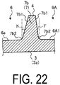
- FIG. 22 is an enlarged cross-sectional view illustrating the configuration of the inner peripheral rib 7b according to the second modification of the embodiment. As illustrated in FIG. 22 , the inner peripheral rib 7b according to the second modification has the tapered side surface 7b1.
- the side surface 7b1 is inclined with respect to the back surface 4 so that an inlet side of recessed portions 6 and 6A in contact with each other is widened.
- An inclination angle ⁇ of the side surface 7b 1 is in the range of, for example, 1° to 5°, and is preferably in the range of 2° to 3°.
- the inner peripheral rib 7b has the tapered side surface 7b1, so that a molded article to be fired later to become the body portion 2 is molded with a mold, and then the mold can be easily removed from the molded article in the manufacturing process of the mirror 1.
- the molded article to be the body portion 2 can be easily molded with the mold, so that the mirror 1 can be easily manufactured. Furthermore, in the second modification, a distal end side of the inner peripheral rib 7b can be thinned, so that the mirror 1 can be reduced in weight.
- the corner portion 7b2 located at a lower end of the inner peripheral rib 7b has an R shape.
- Such a corner portion 7b2 is a portion where the side surface 7b1 of the inner peripheral rib 7b and the bottom surface 6a of the recessed portion 6 or a bottom surface 6A1 of the recessed portion 6A are in contact with each other.
- corner portion 7b2 of the inner peripheral rib 7b has an R shape, stress can be suppressed from being concentrated on the corner portion 7b2, so that the strength in the vicinity of the inner peripheral rib 7b in the body portion 2 can be improved.
- the side surfaces 7b1 on both sides may be tapered together. Accordingly, after the molded article to be the body portion 2 is molded with the mold, the mold can be more easily removed from the molded article.
- the present invention is not limited to the embodiments described above, and various modifications can be made without departing from the essential spirit of the present invention.
- the mirror 1 having a disk shape has been described; however, the shape of the mirror 1 is not limited to the disk shape and can be appropriately changed according to the specifications of various devices to which the mirror 1 is applied.
- the body portion 2 is configured by connecting six split members 10 ; however, the number of split members 10 constituting the body portion 2 is not limited to six.
- the mirror 1 includes a mirror surface 3a provided on a front surface 3 of a plate-shaped body portion 2 made of ceramics, recessed portions 6 formed on a back surface 4 of the body portion 2, and a rib 7 (an outer peripheral rib 7a, an inner peripheral rib 7b, and a connection rib 7c) provided along edges of the recessed portions 6 and including tapered side surfaces 7a1, 7b1, and 7c1.
- a rib 7 an outer peripheral rib 7a, an inner peripheral rib 7b, and a connection rib 7c
- the mirror surface 3a is a curved surface
- the bottom surface 6a of the recessed portion 6 is a curved surface along the shape of the mirror surface 3a. This makes it possible to reduce the weight of the mirror 1.
- the mirror surface 3a is a curved surface
- the bottom surface 6a of the recessed portion 6 is in a stepped shape along the shape of the mirror surface 3a. This makes it possible to reduce the manufacturing cost of the mirror 1.
- the mirror surface 3a is a curved surface
- the bottom surface 6a of the recessed portion 6 is a flat surface along the shape of the mirror surface 3a. This makes it possible to reduce the manufacturing cost of the mirror 1, and to further reduce the weight of the mirror 1.
- the rib 7 includes the outer peripheral rib 7a provided on the outer peripheral side of the back surface 4, the inner peripheral rib 7b provided on the inner peripheral side of the back surface 4, and the connection rib 7c provided to connect the outer peripheral rib 7a and the inner peripheral rib 7b.
- the width of the outer peripheral rib 7a is wider than that of the inner peripheral rib 7b and that of the connection rib 7c. This makes it possible to further improve the strength of the mirror 1.
- the body portion 2 has a disk shape, and has a flat portion 8 on a part of the side surface on the outer peripheral side. Accordingly, the dimensional accuracy of the body portion 2 can be improved, and positioning can be facilitated when the mirror 1 is installed in an astronomical telescope.
- the body portion 2 is configured by connecting the plurality of split members 10 having the same shape. Accordingly, the mirror 1 can be easily increased in size, and even when a part of the mirror 1 is damaged, only the damaged portion can be replaced.
- adjacent split members 10 are connected by the fastening members 20 that penetrate through a part (partial rib 7d) of the rib (connection rib 7c). This makes it possible to improve the surface accuracy of the mirror 1.
- adjacent split members 10 are connected via the plate-shaped member 21 disposed to cover a part (partial rib 7d) of the rib (connection rib 7c). This makes it possible to improve the surface accuracy of the mirror 1.
Landscapes
- Physics & Mathematics (AREA)
- General Physics & Mathematics (AREA)
- Optics & Photonics (AREA)
- Optical Elements Other Than Lenses (AREA)
- Telescopes (AREA)
Abstract
Description
- An embodiment of the present disclosure relates to a mirror.
- An astronomical telescope or the like is provided with a mirror for reflecting light from an observation target. As such a mirror, for example, a mirror for an astronomical telescope including a mirror member having a reflecting surface for reflecting light and made of low thermal expansion ceramics and a reflecting film provided on the reflecting surface of such a mirror member is disclosed (see PTL 1).
- PTL 1:
JP 2005-234344 - A mirror according to an aspect of an embodiment includes a mirror surface provided on a front surface of a body portion, having a plate shape and made of ceramics, a recessed portion formed on a back surface of the body portion, and a rib provided along an edge of the recessed portion and including a tapered side surface.
-
-
FIG. 1 is a plan view of a mirror according to an embodiment when viewed from a front surface side. -
FIG. 2 is a plan view of a mirror according to the embodiment when viewed from a back surface side. -
FIG. 3 is a cross-sectional view taken along line A-A in a direction of arrows illustrated inFIG. 2 . -
FIG. 4 is a cross-sectional view taken along line B-B in a direction of arrows illustrated inFIG. 2 . -
FIG. 5 is an enlarged cross-sectional view illustrating the configuration of an outer peripheral rib according to the embodiment. -
FIG. 6 is an enlarged cross-sectional view illustrating another configuration of an outer peripheral rib according to the embodiment. -
FIG. 7 is an enlarged cross-sectional view illustrating the configuration of an inner peripheral rib according to the embodiment. -
FIG. 8 is an enlarged cross-sectional view illustrating the configuration of a bottom surface of a recessed portion according to the embodiment. -
FIG. 9 is an enlarged cross-sectional view illustrating another configuration of a bottom surface of a recessed portion according to the embodiment. -
FIG. 10 is an enlarged cross-sectional view illustrating another configuration of a bottom surface of a recessed portion according to the embodiment. -
FIG. 11 is a plan view illustrating another configuration of a body portion according to the embodiment. -
FIG. 12 is a plan view of a mirror according to a first modification of the embodiment when viewed from a front surface side. -
FIG. 13 is a plan view of the mirror according to the first modification of the embodiment when viewed from a back surface side. -
FIG. 14 is a plan view of a split member according to the first modification of the embodiment when viewed from a back surface side. -
FIG. 15 is a cross-sectional view taken along line C-C in a direction of arrows illustrated inFIG. 13 . -
FIG. 16 is an enlarged cross-sectional view illustrating another configuration of a connection rib according to the first modification of the embodiment. -
FIG. 17 is a perspective view illustrating another configuration of a body portion according to the first modification of the embodiment. -
FIG. 18 is a plan view illustrating another configuration of a body portion according to the first modification of the embodiment. -
FIG. 19 is a plan view of a mirror according to a second modification of the embodiment when viewed from a front surface side. -
FIG. 20 is a plan view of a mirror according to the second modification of the embodiment when viewed from a back surface side. -
FIG. 21 is a cross-sectional view taken along line D-D in a direction of arrows illustrated inFIG. 20 . -
FIG. 22 is an enlarged cross-sectional view illustrating the configuration of an inner peripheral rib according to the second modification of the embodiment. - Hereinafter, embodiments of a mirror disclosed in the present disclosure will be described with reference to the accompanying drawings. Note that the present invention is not limited to the embodiments that will be described below. In each of the following embodiments, the same reference numerals are assigned to the same portions and redundant descriptions thereof will be omitted.
- An astronomical telescope or the like is provided with a mirror for reflecting light from an observation target. As such a mirror, for example, a mirror for an astronomical telescope including a mirror member having a reflecting surface for reflecting light and made of low thermal expansion ceramics and a reflecting film provided on the reflecting surface of such a mirror member is disclosed.
- However, in the related art, since a core member for reinforcing the mirror member is separately required, in a manufacturing process of a mirror, a step of manufacturing the core member, a step of bonding the mirror member and the core member, and the like are separately required. That is, in the related art, it is difficult to easily manufacture the mirror.
- In this regard, it is expected to implement a mirror that can overcome the aforementioned problems and can be easily manufactured.
- First, an overall configuration of a
mirror 1 according to an embodiment will be described with reference toFIG. 1 to FIG. 3 .FIG. 1 is a plan view of themirror 1 according to the embodiment when viewed from afront surface 3 side,FIG. 2 is a plan view of themirror 1 according to the embodiment when viewed from aback surface 4 side, andFIG. 3 is a cross-sectional view taken along line A-A in a direction of arrows inFIG. 2 . - Although the
mirror 1 used in an astronomical telescope will be described in the present disclosure, a device including themirror 1 according to the embodiment applied thereto is not limited to the astronomical telescope. - As illustrated in
FIG. 1 to FIG. 3 , themirror 1 according to the embodiment includes a plate-shaped (disk-shaped in the present disclosure)body portion 2 made of ceramics. Such abody portion 2 is provided with afront surface 3 and aback surface 4. Thefront surface 3 has a curved (for example, spherical)mirror surface 3a on the entire surface thereof. - The
mirror surface 3a is formed by, for example, mirror-polishing thefront surface 3 entirely and then applying a coating that reflects light to such a mirror surface. Themirror 1 according to the embodiment can reflect light from an observation target on themirror surface 3a. - The present disclosure describes a case where the
mirror surface 3a has a recessed shape, but the shape of themirror surface 3a is not limited to the recessed shape and may be a planar shape or a convex shape. Furthermore, themirror surface 3a is not limited to a spherical surface, and may be an aspherical surface. - As illustrated in
FIG. 3 and the like, thebody portion 2 is formed in the center portion thereof with a cylindrical throughhole 5 that penetrates from thefront surface 3 to theback surface 4. In the astronomical telescope to which themirror 1 is applied, light passing through such a throughhole 5 can be observed by a sub-mirror. - As illustrated in
FIG. 2 and the like, a plurality ofrecessed portions 6 are formed on theback surface 4 of thebody portion 2. Such arecessed portion 6 has, for example, a fan shape having a center angle of about 60°in the plan view. On theback surface 4, six recessedportions 6 are equally disposed along the circumferential direction of the disk-shaped body portion 2. - Furthermore, a
rib 7 is provided on theback surface 4 of thebody portion 2 along edges of such recessedportions 6. As illustrated inFIG. 3 , therib 7 is provided to rise substantially perpendicular from thebottom surfaces 6a of therecessed portions 6 toward theback surface 4. - Furthermore, as illustrated in
FIG. 2 , therib 7 includes an outerperipheral rib 7a provided on an outer peripheral side of theback surface 4, an innerperipheral rib 7b provided on an inner peripheral side of theback surface 4, and aconnection rib 7c provided to connect the outerperipheral rib 7a and the innerperipheral rib 7b. - The outer
peripheral rib 7a is provided along an outer edge portion of theback surface 4, for example. The innerperipheral rib 7b is provided between the throughhole 5 and therecessed portions 6 to surround the throughhole 5, for example. Theconnection rib 7c is provided radially from a center portion of theback surface 4 toward the outer edge portion of theback surface 4, for example. - In the embodiment, by forming the plurality of
recessed portions 6 in thebody portion 2, the volume of themirror 1 can be reduced, so that themirror 1 can be reduced in weight. Furthermore, in the embodiment, therib 7 is formed along the edges of therecessed portions 6, so that the strength of themirror 1 reduced in weight by therecessed portion 6 can be ensured. - Subsequently, details of the
rib 7 according to the embodiment will be described with reference toFIG. 4 to FIG. 7 .FIG. 4 is a cross-sectional view taken along line B-B in a direction of arrows inFIG. 2 , and is an enlarged cross-sectional view illustrating the configuration of theconnection rib 7c according to the embodiment. - As illustrated in
FIG. 4 , theconnection rib 7c according to the embodiment has tapered side surfaces 7c1. Such a side surface 7c1 is inclined with respect to theback surface 4 so that an inlet side of a recessedportion 6 in contact with the side surface 7c1 is widened. An inclination angle α of the side surface 7c1 is in the range of, for example, 1° to 5°, and is preferably in the range of 2° to 3°. - In the embodiment, the
connection rib 7c has the tapered side surfaces 7c1, so that a molded article to be fired later to become thebody portion 2 is molded with a mold, and then such a mold can be easily removed from the molded article in the manufacturing process of themirror 1. - Consequently, according to the embodiment, the molded article to be the
body portion 2 can be easily molded with the mold, so that themirror 1 can be easily manufactured. Furthermore, in the embodiment, a distal end side of theconnection rib 7c can be thinned, so that themirror 1 can be reduced in weight. - Furthermore, in the embodiment, it is preferable that a corner portion 7c2 located at a lower end of the
connection rib 7c has an R shape. Such a corner portion 7c2 is a portion where the side surface 7c1 of theconnection rib 7c and thebottom surface 6a of the recessedportion 6 are in contact with each other. - In this way, since the corner portion 7c2 of the
connection rib 7c has an R shape, stress can be suppressed from being concentrated on such a corner portion 7c2, so that the strength in the vicinity of theconnection rib 7c in thebody portion 2 can be improved. - As illustrated in
FIG. 4 , the side surfaces 7c1 on both sides of theconnection ribs 7c may be tapered together. Accordingly, after the molded article to be thebody portion 2 is molded with the mold, such a mold can be more easily removed from the molded article. -
FIG. 5 is an enlarged cross-sectional view illustrating the configuration of the outerperipheral rib 7a according to the embodiment. As illustrated inFIG. 5 , the outerperipheral rib 7a according to the embodiment has tapered side surfaces 7a1. Of the side surfaces 7a1 on both sides, a side surface 7a1 in contact with the recessedportion 6 is inclined with respect to theback surface 4 so that the inlet side of such a recessedportion 6 is widened. - Furthermore, of the side surfaces 7a1 on both sides, a side surface 7a1 to be the side surface of the
body portion 2 on the outer peripheral side is inclined with respect to theback surface 4 so that theback surface 4 side is closer to the center of thebody portion 2 than thefront surface 3 side. An inclination angle β of the side surface 7a1 is in the range of, for example, 1° to 5°, and is preferably in the range of 2° to 3°. - In the embodiment, the outer
peripheral rib 7a has the tapered side surface 7a1, so that the molded article to be fired later to become thebody portion 2 is molded with the mold, and then such a mold can be easily removed from the molded article in the manufacturing process of themirror 1. - Consequently, according to the embodiment, the molded article to be the
body portion 2 can be easily molded with the mold, so that themirror 1 can be easily manufactured. Furthermore, in the embodiment, a distal end side of the outerperipheral rib 7a can be thinned, so that themirror 1 can be reduced in weight. - Furthermore, in the embodiment, it is preferable that the corner portion 7a2 located at a lower end of the outer
peripheral rib 7a has an R shape. Such a corner portion 7a2 is a portion where the side surface 7a1 of the outerperipheral rib 7a and thebottom surface 6a of the recessedportion 6 are in contact with each other. - In this way, since the corner portion 7a2 of the outer
peripheral rib 7a has an R shape, stress can be suppressed from being concentrated on the corner portion 7a2, so that the strength in the vicinity of the outerperipheral rib 7a in thebody portion 2 can be improved. - The side surfaces 7a1 on both sides of the outer
peripheral rib 7a may be tapered together as illustrated inFIG. 5 , or only a side surface 7a1 in contact with the recessedportion 6 may be tapered as illustrated inFIG. 6. FIG. 6 is an enlarged cross-sectional view illustrating another configuration of the outerperipheral rib 7a according to the embodiment. - As illustrated in
FIG. 5 , by making both side surfaces 7a1 tapered together, after the molded article to be thebody portion 2 is molded with the mold, such a mold can be more easily removed from the molded article. - Furthermore, as illustrated in
FIG. 6 , even when the side surface 7a1 serving as the outer peripheral side of thebody portion 2 is formed substantially perpendicular to theback surface 4, the mold in contact with the side surface 7a1 can be pulled out to the outer peripheral side of the molded article, so that the mold can be pulled out without any particular problem. -
FIG. 7 is an enlarged cross-sectional view illustrating the configuration of the innerperipheral rib 7b according to the embodiment. As illustrated inFIG. 7 , such an innerperipheral rib 7b according to the embodiment has tapered side surfaces 7b1. Of the side surfaces 7b1 on both sides, a side surface 7b1 in contact with the recessedportion 6 is inclined with respect to theback surface 4 so that the inlet side of such a recessedportion 6 is widened. - An inclination angle γ of such a side surface 7b1 is in the range of, for example, 1° to 5°, and is preferably is in the range of 2° to 3°.
- In the embodiment, the inner
peripheral rib 7b has the tapered side surfaces 7b1, so that the molded article to be fired later to become thebody portion 2 is molded with the mold, and then the mold can be easily removed from the molded article, in the manufacturing process of themirror 1. - Consequently, according to the embodiment, the molded article to be the
body portion 2 can be easily molded with the mold, so that themirror 1 can be easily manufactured. Furthermore, in the embodiment, a distal end side of the innerperipheral rib 7b can be thinned, so that themirror 1 can be reduced in weight. - As illustrated in
FIG. 7 , in the innerperipheral rib 7b, only a side surface 7b1 in contact with the recessedportion 6 is preferably tapered. In this way, even when a side surface 7b1 in contact with the throughhole 5 is formed substantially perpendicular to theback surface 4, the mold in contact with such a side surface 7b1 is pulled out along the axial direction of the through hole, so that the mold can be pulled out without any particular problem. - Furthermore, in the embodiment, it is preferable that the corner portion 7b2 located at a lower end of the inner
peripheral rib 7b has an R shape. Such a corner portion 7b2 is a portion where the side surface 7b1 of the innerperipheral rib 7b and thebottom surface 6a of the recessedportion 6 are in contact with each other. - In this way, since the corner portion 7b2 of the inner
peripheral rib 7b has an R shape, stress can be suppressed from being concentrated on such a corner portion 7b2, so that the strength in the vicinity of the innerperipheral rib 7b in thebody portion 2 can be improved. - Furthermore, in the embodiment, a width of the outer
peripheral rib 7a is preferably wider than that of the innerperipheral rib 7b and that of theconnection rib 7c. This can further improve the strength of themirror 1. - Subsequently, details of components other than the
rib 7 according to the embodiment will be described with reference toFIG. 8 to FIG. 11 .FIG. 8 is an enlarged cross-sectional view illustrating the configuration of thebottom surface 6a of the recessedportion 6 according to the embodiment. - As illustrated in
FIG. 8 , thebottom surface 6a of the recessedportion 6 according to the embodiment is preferably a curved surface along the shape of themirror surface 3a. In this way, themirror 1 can be reduced in weight by making a wall thickness between themirror surface 3a and thebottom surface 6a constant. - The
bottom surface 6a of the recessedportion 6 according to the embodiment is not limited to the curved surface along the shape of themirror surface 3a.FIG. 9 is an enlarged cross-sectional view illustrating another configuration of thebottom surface 6a of the recessedportion 6 according to the embodiment. - As illustrated in
FIG. 9 , thebottom surface 6a of the recessedportion 6 according to the embodiment may in a stepped shape along the shape of themirror surface 3a. In this way, by configuring thebottom surface 6a in a stepped shape including a plurality of flat surfaces, the mold can be easily formed as compared with a case where thebottom surface 6a includes many curved surfaces, so that the manufacturing cost of themirror 1 can be reduced. -
FIG. 9 illustrates an example in which a stepped portion that connects the flat surfaces of thebottom surface 6a has a taper, but since such a stepped portion has a small step difference of about 1 mm, it does not necessarily have to have a taper. -
FIG. 10 is an enlarged cross-sectional view illustrating another configuration of thebottom surface 6a of the recessedportion 6 according to the embodiment. As illustrated inFIG. 10 , thebottom surface 6a of the recessedportion 6 according to the embodiment may be a flat surface along the shape of themirror surface 3a. - In this way, by configuring the
bottom surface 6a with one flat surface, the mold can be easily formed as compared with the case where thebottom surface 6a includes many curved surfaces, so that the manufacturing cost of themirror 1 can be reduced. Furthermore, in the example ofFIG. 10 , the wall thickness between themirror surface 3a and thebottom surface 6a can be made as thin as possible, so that themirror 1 can be further reduced in weight. -
FIG. 11 is a plan view illustrating another configuration of thebody portion 2 according to the embodiment. As illustrated inFIG. 11 , thebody portion 2 may have aflat portion 8 on a part of the side surface on the outer peripheral side thereof. In this way, theflat portion 8 is provided to a part of the side surface in thebody portion 2, so that positioning can be facilitated in the process of processing thebody portion 2. - Consequently, according to the embodiment, the dimensional accuracy of the
body portion 2 can be improved. Furthermore, theflat portion 8 is provided to a part of the side surface in thebody portion 2, so that positioning can be facilitated when themirror 1 is installed in an astronomical telescope. - As the ceramics constituting the
body portion 2, for example, cordierite ceramics, aluminum oxide ceramics, zirconium oxide ceramics, silicon nitride ceramics, aluminum nitride ceramics, silicon carbide ceramics, mullite ceramics, and the like can be used. - The
body portion 2 is made of ceramics, so that themirror 1 having high mechanical strength and excellent heat resistance can be implemented. Particularly, thebody portion 2 is made of cordierite ceramics having a low specific gravity and a low thermal expansion rate, so that themirror 1 can be reduced in weight and reliability can be improved under an environment where the temperature changes drastically. - The cordierite ceramics contains 80 mass% of cordierite (2MgO · 2Al2O3 · 5SiO2) out of 100 mass% of all components constituting the ceramics.
- The material of the
body portion 2 may be confirmed by the following method. First, x-ray diffraction measurement is performed in the range of a diffraction angle 2θ = (8° to 100°) by an X-ray diffraction (XRD) device using Cu-Kα rays. - When the content of the cordierite calculated using a Rietveld analysis program RIETAN is 80 mass% or more, the material of the
body portion 2 can be regarded as cordierite ceramics. - Subsequently, a manufacturing process of the
mirror 1 according to the embodiment will be described. In the following description, a case where thebody portion 2 is made of cordierite ceramics will be described. - First, synthetic cordierite powder, which is obtained by calcining and synthesizing mixed powder obtained by blending magnesium carbonate powder, aluminum oxide powder, and silicon oxide powder at a predetermined ratio, is prepared.
- Next, the obtained synthetic cordierite powder and sintering aid powder are weighed at a predetermined ratio and used as primary raw materials. Next, the obtained primary raw material powders are wet-mixed, and then a predetermined amount of binder is added to obtain a slurry.
- Next, the obtained slurry is poured into a mold processed into a predetermined shape in advance, is dried at a predetermined temperature and time to be solidified, and then is molded by a cast molding method or the like for demolding. Moreover, machine-cutting and the like are performed to obtain a molded article having any shape.
- Next, the obtained molded article is fired in a firing furnace at a maximum temperature of 1,300°C or higher and 1,450°C or less in an air atmosphere, so that a fired body is obtained. Thereafter, grinding, polishing, coating, and the like are performed on the fired body as necessary, so that the
body portion 2 according to the embodiment can be obtained. - Subsequently, a first modification of the
mirror 1 according to the embodiment will be described with reference toFIG. 12 to FIG. 18 .FIG. 12 is a plan view of amirror 1 according to the first modification of the embodiment when viewed from thefront surface 3 side,FIG. 13 is a plan view of themirror 1 according to the first modification of the embodiment when viewed from theback surface 4 side, andFIG. 14 is a plan view of asplit member 10 according to the first modification of the embodiment when viewed from theback surface 4 side. - As illustrated in
FIG. 12 and the like, themirror 1 according to the first modification is different from the embodiment in that an overall shape is the same as that of themirror 1 according to the embodiment, but a plurality ofsplit members 10 having the same shape are connected to configure thebody portion 2. - For example, six split members 10 (see
FIG. 14 ) having a fan shape with a central angle of 60° in the plan view can be connected to configure thebody portion 2 of the first modification. - In this way, the
body portion 2 is configured by connecting the plurality ofsplit members 10 having the same shape, so that themirror 1 can be easily increased in size. Furthermore, since thebody portion 2 is configured by connecting the plurality ofsplit members 10 having the same shape, even when a part of themirror 1 is damaged, only the damaged portion can be replaced. - As illustrated in
FIG. 14 , the recessedportion 6 is formed in the center portion of such asplit member 10, and the outerperipheral rib 7a, the innerperipheral rib 7b, and apartial rib 7d (corresponding to a part of theconnection rib 7c) are formed along the edge of the recessedportion 6, so that themirror 1 having the configuration shown in the aforementioned embodiment can be implemented. -
FIG. 15 is a cross-sectional view taken along line C-C in a direction of arrows inFIG. 13 , and is an enlarged cross-sectional view illustrating the configuration of theconnection rib 7c according to the first modification. As illustrated inFIG. 15 , theconnection rib 7c according to the first modification is configured by connecting thepartial ribs 7d of thesplit members 10. - The
connection rib 7c according to the first modification has the tapered side surface 7c1 as in the aforementioned embodiment. Since the configurations of the outerperipheral rib 7a and the innerperipheral rib 7b in themirror 1 of first modification are the same as those of the aforementioned embodiment, description thereof will be omitted. - In the first modification, the
connection rib 7c has the tapered side surface 7c1, so that a molded article to be fired later to become thesplit member 10 is molded with a mold, and then the mold can be easily removed from the molded article in the manufacturing process of themirror 1. - Consequently, according to the first modification, the molded article to be the
split member 10 can be easily molded with the mold, so that themirror 1 can be easily manufactured. Furthermore, in the first modification, a distal end side of theconnection rib 7c can be thinned, so that themirror 1 can be reduced in weight. - In the first modification, the plurality of
split members 10 can be connected by adhering contact surfaces, where thesplit members 10 are in contact with each other, by a bonding material or the like. - Furthermore, as illustrated in
FIG. 16 ,fastening members 20 such as bolts and nuts may be used to connectadjacent split members 10.FIG. 16 is an enlarged cross-sectional view illustrating another configuration of theconnection rib 7c according to the first modification of the embodiment. - Specifically, through holes extending through the
partial rib 7d of thesplit member 10 in the horizontal direction are formed, the through holes of adjacentpartial ribs 7d are communicated with each other, and thefastening members 20 are inserted into the communicating through holes, so that theadjacent split members 10 can be connected together. - In this way, since the plurality of
split members 10 are connected by using thefastening members 20, even when vibration or the like is applied when themirror 1 is attached to an astronomical telescope, heights of thefront surfaces 3 ofadjacent split members 10 can be suppressed from being shifted. Consequently, according to the example ofFIG. 16 , the surface accuracy of themirror 1 can be improved. - In the example of
FIG. 16 , it is preferable that a flat surface substantially perpendicular to the axial direction of the through hole is formed around the throughhole 5 on the side surface 7c1 of thepartial rib 7d. When thefastening member 20 is brought into direct contact with the side surface 7c1 having a taper without forming such a flat surface, a great stress is applied to a part of the side surface 7c1 inclined from thefastening members 20, which may damage thepartial rib 7d when fastening. - However, in the example of
FIG. 16 , since a flat surface substantially perpendicular to the axial direction of the through hole is formed around the throughhole 5 on the side surface 7c1, stress is evenly applied to such a flat surface from thefastening members 20, so that thepartial rib 7d can be suppressed from being damaged when fastening. - Furthermore, in the first modification, it is preferable that the arithmetic average roughness Ra of the contact surface, where the
split members 10 are in contact with each other, is 0.8 µm or less and the flatness per unit length is 5 µm or less. Accordingly, a contact betweenadjacent split members 10 is good, so that a gap between thefront surfaces 3 of theadjacent split members 10 can be reduced. - Consequently, according to the first modification, the surface accuracy of the
mirror surface 3a configured by a set of thefront surfaces 3 of thesplit members 10 can be improved. - Furthermore, a member for bonding
adjacent split members 10 is not limited to thefastening member 20.FIG. 17 is a perspective view illustrating another configuration of thebody portion 2 according to the first modification of the embodiment. - As illustrated in
FIG. 17 ,adjacent split members 10 may be connected via a plate-shapedmember 21 disposed to cover thepartial rib 7d. A plurality of throughholes 21a are formed in such a plate-shapedmember 21, and screw holes 7d1 are formed on a surface of thepartial rib 7d on theback face 4 side at positions corresponding to such throughholes 21a. - The plate-shaped
member 21 is disposed to cover adjacentpartial ribs 7d, andbolts 22 are screwed into the throughholes 21a and the screw holes 7d1, so that theadjacent split members 10 can be connected via the plate-shapedmember 21. - In this way, since the plurality of
split members 10 are connected by using the plate-shapedmembers 21, even when vibration or the like is applied when themirror 1 is attached to an astronomical telescope, heights of thefront surfaces 3 ofadjacent split members 10 can be suppressed from being shifted. Consequently, according to the example ofFIG. 17 , the surface accuracy of themirror 1 can be improved. -
FIG. 17 illustrates an example in which the plurality ofsplit members 10 are connected by using the plate-shapedmember 21 and thefastening members 20, but the plurality ofsplit members 10 may be connected by using only the plate-shapedmember 21 without using thefastening members 20. -
FIG. 18 is a plan view illustrating another configuration of thebody portion 2 according to the first modification of the embodiment. As illustrated inFIG. 18 , thebody portion 2 of the first modification may have aflat portion 8 on a part of the side surface on the outer peripheral side thereof. In this way, theflat portion 8 is provided to a part of the side surface in thebody portion 2, so that positioning can be facilitated in the process of processing thebody portion 2. - Consequently, according to the first modification, the dimensional accuracy of the
body portion 2 can be improved. Furthermore, theflat portion 8 is provided to a part of the side surface in thebody portion 2, so that positioning can be facilitated when themirror 1 is installed in an astronomical telescope. - Subsequently, a second modification of the
mirror 1 according to the embodiment will be described with reference toFIG. 19 to FIG. 22 .FIG. 19 is a plan view of themirror 1 according to the second modification of the embodiment when viewed from thefront side 3 side,FIG. 20 is a plan view of themirror 1 according to the second modification of the embodiment when viewed from theback surface 4 side, andFIG. 21 is a cross-sectional view taken along the line D-D in a direction of arrows inFIG. 20 . - As illustrated in
FIG. 19 and the like, themirror 1 according to the second modification is different from the embodiment in that a recessedportion 6A is formed in the center portion of thebody portion 2 instead of the throughhole 5. In this way, since the throughhole 5 is not formed, an area of themirror surface 3a can be enlarged, so that the amount of light reflected from an observation target can be increased. -
FIG. 22 is an enlarged cross-sectional view illustrating the configuration of the innerperipheral rib 7b according to the second modification of the embodiment. As illustrated inFIG. 22 , the innerperipheral rib 7b according to the second modification has the tapered side surface 7b1. - The side surface 7b1 is inclined with respect to the
back surface 4 so that an inlet side of recessedportions side surface 7b - In the second modification, the inner
peripheral rib 7b has the tapered side surface 7b1, so that a molded article to be fired later to become thebody portion 2 is molded with a mold, and then the mold can be easily removed from the molded article in the manufacturing process of themirror 1. - Consequently, according to the second modification, the molded article to be the
body portion 2 can be easily molded with the mold, so that themirror 1 can be easily manufactured. Furthermore, in the second modification, a distal end side of the innerperipheral rib 7b can be thinned, so that themirror 1 can be reduced in weight. - Furthermore, in the embodiment, it is preferable that the corner portion 7b2 located at a lower end of the inner
peripheral rib 7b has an R shape. Such a corner portion 7b2 is a portion where the side surface 7b1 of the innerperipheral rib 7b and thebottom surface 6a of the recessedportion 6 or a bottom surface 6A1 of the recessedportion 6A are in contact with each other. - In this way, since the corner portion 7b2 of the inner
peripheral rib 7b has an R shape, stress can be suppressed from being concentrated on the corner portion 7b2, so that the strength in the vicinity of the innerperipheral rib 7b in thebody portion 2 can be improved. - As illustrated in
FIG. 22 , in the innerperipheral rib 7b of the second modification, the side surfaces 7b1 on both sides may be tapered together. Accordingly, after the molded article to be thebody portion 2 is molded with the mold, the mold can be more easily removed from the molded article. - Embodiments according to the present invention were described above. However, the present invention is not limited to the embodiments described above, and various modifications can be made without departing from the essential spirit of the present invention. For example, in the aforementioned embodiment, the
mirror 1 having a disk shape has been described; however, the shape of themirror 1 is not limited to the disk shape and can be appropriately changed according to the specifications of various devices to which themirror 1 is applied. - Furthermore, in the aforementioned embodiment, an example in which the
body portion 2 is configured by connecting six splitmembers 10 has been described; however, the number ofsplit members 10 constituting thebody portion 2 is not limited to six. - As described above, the
mirror 1 according to the embodiment includes amirror surface 3a provided on afront surface 3 of a plate-shapedbody portion 2 made of ceramics, recessedportions 6 formed on aback surface 4 of thebody portion 2, and a rib 7 (an outerperipheral rib 7a, an innerperipheral rib 7b, and aconnection rib 7c) provided along edges of the recessedportions 6 and including tapered side surfaces 7a1, 7b1, and 7c1. This makes it possible to easily manufacture themirror 1. - Furthermore, in the
mirror 1 according to the embodiment, themirror surface 3a is a curved surface, and thebottom surface 6a of the recessedportion 6 is a curved surface along the shape of themirror surface 3a. This makes it possible to reduce the weight of themirror 1. - Furthermore, in the
mirror 1 according to the embodiment, themirror surface 3a is a curved surface, and thebottom surface 6a of the recessedportion 6 is in a stepped shape along the shape of themirror surface 3a. This makes it possible to reduce the manufacturing cost of themirror 1. - Furthermore, in the
mirror 1 according to the embodiment, themirror surface 3a is a curved surface, and thebottom surface 6a of the recessedportion 6 is a flat surface along the shape of themirror surface 3a. This makes it possible to reduce the manufacturing cost of themirror 1, and to further reduce the weight of themirror 1. - Furthermore, in the
mirror 1 according to the embodiment, therib 7 includes the outerperipheral rib 7a provided on the outer peripheral side of theback surface 4, the innerperipheral rib 7b provided on the inner peripheral side of theback surface 4, and theconnection rib 7c provided to connect the outerperipheral rib 7a and the innerperipheral rib 7b. The width of the outerperipheral rib 7a is wider than that of the innerperipheral rib 7b and that of theconnection rib 7c. This makes it possible to further improve the strength of themirror 1. - Furthermore, in the
mirror 1 according to the embodiment, thebody portion 2 has a disk shape, and has aflat portion 8 on a part of the side surface on the outer peripheral side. Accordingly, the dimensional accuracy of thebody portion 2 can be improved, and positioning can be facilitated when themirror 1 is installed in an astronomical telescope. - Furthermore, in the
mirror 1 according to the embodiment, thebody portion 2 is configured by connecting the plurality ofsplit members 10 having the same shape. Accordingly, themirror 1 can be easily increased in size, and even when a part of themirror 1 is damaged, only the damaged portion can be replaced. - Furthermore, in the
mirror 1 according to the embodiment,adjacent split members 10 are connected by thefastening members 20 that penetrate through a part (partial rib 7d) of the rib (connection rib 7c). This makes it possible to improve the surface accuracy of themirror 1. - Furthermore, in the
mirror 1 according to the embodiment,adjacent split members 10 are connected via the plate-shapedmember 21 disposed to cover a part (partial rib 7d) of the rib (connection rib 7c). This makes it possible to improve the surface accuracy of themirror 1. - Additional effects and other aspects can be easily derived by a person skilled in the art. Thus, a wide variety of aspects of the present invention are not limited to the specific details and representative embodiments represented and described above. Accordingly, various changes are possible without departing from the spirit or scope of the general inventive concepts defined by the appended claims and their equivalents.
-
- 1 Mirror
- 2 Body portion
- 3 Front surface
- 3a Mirror surface
- 4 Back surface
- 5 Through hole
- 6 Recessed portion
- 6a Bottom surface
- 7 Rib
- 7a Outer peripheral rib
- 7b Inner peripheral rib
- 7c Connection rib
- 7d Partial rib
- 7a1 to 7c 1 Side surface
- 8 Flat portion
- 10 Split member
- 20 Fastening member
- 21 Plate-shaped member
Claims (9)
- A mirror comprising:a mirror surface provided on a front surface of a body portion, having a plate shape and made of ceramics;a recessed portion formed on a back surface of the body portion; and a rib provided along an edge of the recessed portion and comprising a tapered side surface.
- The mirror according to claim 1, whereinthe mirror surface is a curved surface, anda bottom surface of the recessed portion is a curved surface along a shape of the mirror surface.
- The mirror according to claim 1, whereinthe mirror surface is a curved surface, anda bottom surface of the recessed portion has a stepped shape along a shape of the mirror surface.
- The mirror according to claim 1, whereinthe mirror surface is a curved surface, anda bottom surface of the recessed portion is a flat surface along a shape of the mirror surface.
- The mirror according to any one of claims 1 to 4, whereinthe rib comprises an outer peripheral rib provided on an outer peripheral side of the back surface, an inner peripheral rib provided on an inner peripheral side of the back surface, and a connection rib provided to connect the outer peripheral rib and the inner peripheral rib, anda width of the outer peripheral rib is wider than a width of the inner peripheral rib and a width of the connection rib.
- The mirror according to any one of claims 1 to 5, wherein the body portion has a disk shape, and comprises a flat portion on a part of a side surface on an outer peripheral side of the body portion.
- The mirror according to any one of claims 1 to 6, wherein the body portion is configured by connecting a plurality of split members having the same shape.
- The mirror according to claim 7, wherein the split members adjacent to each other are connected by a fastening member that penetrates through a part of the rib.
- The mirror according to claim 7 or 8, wherein the split members adjacent to each other are connected via a plate-shaped member disposed to cover a part of the rib.
Applications Claiming Priority (2)
| Application Number | Priority Date | Filing Date | Title |
|---|---|---|---|
| JP2019215322 | 2019-11-28 | ||
| PCT/JP2020/041977 WO2021106557A1 (en) | 2019-11-28 | 2020-11-10 | Mirror |
Publications (3)
| Publication Number | Publication Date |
|---|---|
| EP4067949A1 true EP4067949A1 (en) | 2022-10-05 |
| EP4067949A4 EP4067949A4 (en) | 2024-01-24 |
| EP4067949B1 EP4067949B1 (en) | 2026-01-21 |
Family
ID=76130181
Family Applications (1)
| Application Number | Title | Priority Date | Filing Date |
|---|---|---|---|
| EP20894783.8A Active EP4067949B1 (en) | 2019-11-28 | 2020-11-10 | Mirror |
Country Status (4)
| Country | Link |
|---|---|
| US (1) | US20230036458A1 (en) |
| EP (1) | EP4067949B1 (en) |
| JP (2) | JP7325533B2 (en) |
| WO (1) | WO2021106557A1 (en) |
Family Cites Families (20)
| Publication number | Priority date | Publication date | Assignee | Title |
|---|---|---|---|---|
| GB1581455A (en) * | 1977-06-28 | 1980-12-17 | Bfg Glassgroup | Mirrors |
| JPH052102U (en) * | 1991-06-26 | 1993-01-14 | 日本石英硝子株式会社 | Double-sided quartz glass lightweight mirror |
| US5227921A (en) | 1991-11-27 | 1993-07-13 | Plx Inc. | Light-weighted optical assembly |
| US5565052A (en) * | 1992-03-05 | 1996-10-15 | Industrieanlagen-Betriebsgesellschaft Gmbh | Method for the production of a reflector |
| JP2884555B2 (en) * | 1993-09-30 | 1999-04-19 | 信越石英株式会社 | Lightweight reflector |
| JP3596530B2 (en) | 2002-02-18 | 2004-12-02 | 三菱マテリアル株式会社 | Blade for forming ribs |
| US20030234991A1 (en) | 2002-06-20 | 2003-12-25 | Alan Adler | Optical mirror flexing structure and assembly |
| FR2857660B1 (en) | 2003-07-18 | 2006-03-03 | Snecma Propulsion Solide | THERMOSTRUCTURAL COMPOSITE STRUCTURE HAVING A COMPOSITION GRADIENT AND METHOD OF MANUFACTURING THE SAME |
| US7288013B2 (en) | 2003-10-31 | 2007-10-30 | 3M Innovative Properties Company | Method of forming microstructures on a substrate and a microstructured assembly used for same |
| JP2005195706A (en) | 2003-12-26 | 2005-07-21 | Hisanori Sako | Concave mirror capable of disassembling and assembling |
| JP2009205108A (en) * | 2008-02-29 | 2009-09-10 | Mitsubishi Electric Corp | Lightweight mirror and manufacturing method therefor |
| JP2009276378A (en) | 2008-05-12 | 2009-11-26 | Mitsubishi Electric Corp | Lightweight mirror and method of manufacturing the same |
| JP5294952B2 (en) * | 2009-04-03 | 2013-09-18 | 三菱電機株式会社 | Mirror structure |
| JP5652845B2 (en) | 2009-06-01 | 2015-01-14 | Nec東芝スペースシステム株式会社 | Optical equipment for spacecraft |
| DE102011008953B4 (en) * | 2011-01-19 | 2020-08-20 | Schott Ag | Lightweight structure substrate |
| JP5762110B2 (en) | 2011-04-25 | 2015-08-12 | 三菱電機株式会社 | Lightweight mirror |
| DE102011051198B4 (en) * | 2011-06-20 | 2016-11-10 | Scanlab Ag | Method for producing a weight-optimized deflection mirror |
| US9958638B2 (en) * | 2013-09-13 | 2018-05-01 | Raytheon Company | Optimal kinematic mount for large mirrors |
| US10145991B2 (en) * | 2016-07-01 | 2018-12-04 | Harris Corporation | Large lightweight mirror for a large telescope and methods for producing the same |
| EP3895886A4 (en) * | 2018-12-13 | 2022-01-19 | Mitsubishi Electric Corporation | HONEYCOMB SANDWICH PANEL, OPTICAL DEVICE AND ARTIFICIAL SATELLITE |
-
2020
- 2020-11-10 JP JP2021561279A patent/JP7325533B2/en active Active
- 2020-11-10 US US17/780,771 patent/US20230036458A1/en active Pending
- 2020-11-10 EP EP20894783.8A patent/EP4067949B1/en active Active
- 2020-11-10 WO PCT/JP2020/041977 patent/WO2021106557A1/en not_active Ceased
-
2023
- 2023-08-01 JP JP2023125313A patent/JP7518257B2/en active Active
Also Published As
| Publication number | Publication date |
|---|---|
| EP4067949A4 (en) | 2024-01-24 |
| JP7518257B2 (en) | 2024-07-17 |
| JPWO2021106557A1 (en) | 2021-06-03 |
| US20230036458A1 (en) | 2023-02-02 |
| WO2021106557A1 (en) | 2021-06-03 |
| JP2023153922A (en) | 2023-10-18 |
| JP7325533B2 (en) | 2023-08-14 |
| EP4067949B1 (en) | 2026-01-21 |
Similar Documents
| Publication | Publication Date | Title |
|---|---|---|
| JP7101731B2 (en) | Work unit | |
| CN101272956B (en) | Assembly of aircraft components | |
| JP6898074B2 (en) | Whisker reinforced high fracture toughness ceramic tip for radome | |
| KR20190085482A (en) | Setter for firing | |
| KR102525393B1 (en) | Setter for firing | |
| EP4067949B1 (en) | Mirror | |
| JP6902609B2 (en) | Synthetic diamond plate | |
| CN1115732C (en) | Method for producing ceramic diaphragm structure | |
| JP4460325B2 (en) | Astronomical telescope mirror | |
| CN120752734A (en) | Temporary fixing substrate and method for manufacturing the same | |
| JP3585310B2 (en) | Manufacturing method of multi-diaphragm structure | |
| JP6995030B2 (en) | mirror | |
| TWI815002B (en) | Peeling method for temporarily fixed substrates, composite substrates and electronic components | |
| EP3176532B1 (en) | Heat exchanger | |
| JP6679560B2 (en) | Firing setter | |
| EP0691682A2 (en) | Fired body for and manufacture of a substrate | |
| JP6067394B2 (en) | Firing jig | |
| JPWO2018221379A1 (en) | Support substrate | |
| US10933560B2 (en) | Intermediate member | |
| US12145891B2 (en) | Ceramic structural body | |
| JP6356562B2 (en) | Channel member | |
| JP2022028405A (en) | Mirror and telescope | |
| JP2020197303A (en) | Guide member | |
| JP7315486B2 (en) | Ceramic bonded body, manufacturing method thereof, and charged particle beam accelerator | |
| JP2005234338A (en) | Mirror for position measurement |
Legal Events
| Date | Code | Title | Description |
|---|---|---|---|
| STAA | Information on the status of an ep patent application or granted ep patent |
Free format text: STATUS: THE INTERNATIONAL PUBLICATION HAS BEEN MADE |
|
| PUAI | Public reference made under article 153(3) epc to a published international application that has entered the european phase |
Free format text: ORIGINAL CODE: 0009012 |
|
| STAA | Information on the status of an ep patent application or granted ep patent |
Free format text: STATUS: REQUEST FOR EXAMINATION WAS MADE |
|
| 17P | Request for examination filed |
Effective date: 20220527 |
|
| AK | Designated contracting states |
Kind code of ref document: A1 Designated state(s): AL AT BE BG CH CY CZ DE DK EE ES FI FR GB GR HR HU IE IS IT LI LT LU LV MC MK MT NL NO PL PT RO RS SE SI SK SM TR |
|
| DAV | Request for validation of the european patent (deleted) | ||
| DAX | Request for extension of the european patent (deleted) | ||
| P01 | Opt-out of the competence of the unified patent court (upc) registered |
Effective date: 20230505 |
|
| A4 | Supplementary search report drawn up and despatched |
Effective date: 20231222 |
|
| RIC1 | Information provided on ipc code assigned before grant |
Ipc: G02B 23/02 20060101ALI20231218BHEP Ipc: G02B 5/10 20060101ALI20231218BHEP Ipc: G02B 5/08 20060101AFI20231218BHEP |
|
| GRAP | Despatch of communication of intention to grant a patent |
Free format text: ORIGINAL CODE: EPIDOSNIGR1 |
|
| STAA | Information on the status of an ep patent application or granted ep patent |
Free format text: STATUS: GRANT OF PATENT IS INTENDED |
|
| INTG | Intention to grant announced |
Effective date: 20250804 |
|
| GRAS | Grant fee paid |
Free format text: ORIGINAL CODE: EPIDOSNIGR3 |
|
| GRAA | (expected) grant |
Free format text: ORIGINAL CODE: 0009210 |
|
| STAA | Information on the status of an ep patent application or granted ep patent |
Free format text: STATUS: THE PATENT HAS BEEN GRANTED |
|
| AK | Designated contracting states |
Kind code of ref document: B1 Designated state(s): AL AT BE BG CH CY CZ DE DK EE ES FI FR GB GR HR HU IE IS IT LI LT LU LV MC MK MT NL NO PL PT RO RS SE SI SK SM TR |
|
| REG | Reference to a national code |
Ref country code: CH Ref legal event code: F10 Free format text: ST27 STATUS EVENT CODE: U-0-0-F10-F00 (AS PROVIDED BY THE NATIONAL OFFICE) Effective date: 20260121 |
|
| REG | Reference to a national code |
Ref country code: DE Ref legal event code: R096 Ref document number: 602020065679 Country of ref document: DE |
|
| REG | Reference to a national code |
Ref country code: IE Ref legal event code: FG4D |