EP4067884A1 - Tube weld x-ray inspection device - Google Patents
Tube weld x-ray inspection device Download PDFInfo
- Publication number
- EP4067884A1 EP4067884A1 EP21208143.4A EP21208143A EP4067884A1 EP 4067884 A1 EP4067884 A1 EP 4067884A1 EP 21208143 A EP21208143 A EP 21208143A EP 4067884 A1 EP4067884 A1 EP 4067884A1
- Authority
- EP
- European Patent Office
- Prior art keywords
- ray
- image
- image plate
- inspection device
- tube
- Prior art date
- Legal status (The legal status is an assumption and is not a legal conclusion. Google has not performed a legal analysis and makes no representation as to the accuracy of the status listed.)
- Granted
Links
Images



Classifications
-
- G—PHYSICS
- G01—MEASURING; TESTING
- G01N—INVESTIGATING OR ANALYSING MATERIALS BY DETERMINING THEIR CHEMICAL OR PHYSICAL PROPERTIES
- G01N23/00—Investigating or analysing materials by the use of wave or particle radiation, e.g. X-rays or neutrons, not covered by groups G01N3/00 – G01N17/00, G01N21/00 or G01N22/00
- G01N23/02—Investigating or analysing materials by the use of wave or particle radiation, e.g. X-rays or neutrons, not covered by groups G01N3/00 – G01N17/00, G01N21/00 or G01N22/00 by transmitting the radiation through the material
- G01N23/04—Investigating or analysing materials by the use of wave or particle radiation, e.g. X-rays or neutrons, not covered by groups G01N3/00 – G01N17/00, G01N21/00 or G01N22/00 by transmitting the radiation through the material and forming images of the material
- G01N23/043—Investigating or analysing materials by the use of wave or particle radiation, e.g. X-rays or neutrons, not covered by groups G01N3/00 – G01N17/00, G01N21/00 or G01N22/00 by transmitting the radiation through the material and forming images of the material using fluoroscopic examination, with visual observation or video transmission of fluoroscopic images
-
- G—PHYSICS
- G01—MEASURING; TESTING
- G01N—INVESTIGATING OR ANALYSING MATERIALS BY DETERMINING THEIR CHEMICAL OR PHYSICAL PROPERTIES
- G01N23/00—Investigating or analysing materials by the use of wave or particle radiation, e.g. X-rays or neutrons, not covered by groups G01N3/00 – G01N17/00, G01N21/00 or G01N22/00
- G01N23/02—Investigating or analysing materials by the use of wave or particle radiation, e.g. X-rays or neutrons, not covered by groups G01N3/00 – G01N17/00, G01N21/00 or G01N22/00 by transmitting the radiation through the material
- G01N23/06—Investigating or analysing materials by the use of wave or particle radiation, e.g. X-rays or neutrons, not covered by groups G01N3/00 – G01N17/00, G01N21/00 or G01N22/00 by transmitting the radiation through the material and measuring the absorption
- G01N23/18—Investigating the presence of flaws defects or foreign matter
-
- G—PHYSICS
- G01—MEASURING; TESTING
- G01N—INVESTIGATING OR ANALYSING MATERIALS BY DETERMINING THEIR CHEMICAL OR PHYSICAL PROPERTIES
- G01N23/00—Investigating or analysing materials by the use of wave or particle radiation, e.g. X-rays or neutrons, not covered by groups G01N3/00 – G01N17/00, G01N21/00 or G01N22/00
- G01N23/02—Investigating or analysing materials by the use of wave or particle radiation, e.g. X-rays or neutrons, not covered by groups G01N3/00 – G01N17/00, G01N21/00 or G01N22/00 by transmitting the radiation through the material
- G01N23/04—Investigating or analysing materials by the use of wave or particle radiation, e.g. X-rays or neutrons, not covered by groups G01N3/00 – G01N17/00, G01N21/00 or G01N22/00 by transmitting the radiation through the material and forming images of the material
-
- G—PHYSICS
- G01—MEASURING; TESTING
- G01N—INVESTIGATING OR ANALYSING MATERIALS BY DETERMINING THEIR CHEMICAL OR PHYSICAL PROPERTIES
- G01N23/00—Investigating or analysing materials by the use of wave or particle radiation, e.g. X-rays or neutrons, not covered by groups G01N3/00 – G01N17/00, G01N21/00 or G01N22/00
- G01N23/02—Investigating or analysing materials by the use of wave or particle radiation, e.g. X-rays or neutrons, not covered by groups G01N3/00 – G01N17/00, G01N21/00 or G01N22/00 by transmitting the radiation through the material
- G01N23/06—Investigating or analysing materials by the use of wave or particle radiation, e.g. X-rays or neutrons, not covered by groups G01N3/00 – G01N17/00, G01N21/00 or G01N22/00 by transmitting the radiation through the material and measuring the absorption
- G01N23/083—Investigating or analysing materials by the use of wave or particle radiation, e.g. X-rays or neutrons, not covered by groups G01N3/00 – G01N17/00, G01N21/00 or G01N22/00 by transmitting the radiation through the material and measuring the absorption the radiation being X-rays
-
- G—PHYSICS
- G01—MEASURING; TESTING
- G01N—INVESTIGATING OR ANALYSING MATERIALS BY DETERMINING THEIR CHEMICAL OR PHYSICAL PROPERTIES
- G01N23/00—Investigating or analysing materials by the use of wave or particle radiation, e.g. X-rays or neutrons, not covered by groups G01N3/00 – G01N17/00, G01N21/00 or G01N22/00
- G01N23/02—Investigating or analysing materials by the use of wave or particle radiation, e.g. X-rays or neutrons, not covered by groups G01N3/00 – G01N17/00, G01N21/00 or G01N22/00 by transmitting the radiation through the material
- G01N23/06—Investigating or analysing materials by the use of wave or particle radiation, e.g. X-rays or neutrons, not covered by groups G01N3/00 – G01N17/00, G01N21/00 or G01N22/00 by transmitting the radiation through the material and measuring the absorption
- G01N23/083—Investigating or analysing materials by the use of wave or particle radiation, e.g. X-rays or neutrons, not covered by groups G01N3/00 – G01N17/00, G01N21/00 or G01N22/00 by transmitting the radiation through the material and measuring the absorption the radiation being X-rays
- G01N23/087—Investigating or analysing materials by the use of wave or particle radiation, e.g. X-rays or neutrons, not covered by groups G01N3/00 – G01N17/00, G01N21/00 or G01N22/00 by transmitting the radiation through the material and measuring the absorption the radiation being X-rays using polyenergetic X-rays
-
- G—PHYSICS
- G01—MEASURING; TESTING
- G01N—INVESTIGATING OR ANALYSING MATERIALS BY DETERMINING THEIR CHEMICAL OR PHYSICAL PROPERTIES
- G01N33/00—Investigating or analysing materials by specific methods not covered by groups G01N1/00 - G01N31/00
- G01N33/20—Metals
- G01N33/207—Welded or soldered joints; Solderability
-
- G—PHYSICS
- G01—MEASURING; TESTING
- G01T—MEASUREMENT OF NUCLEAR OR X-RADIATION
- G01T1/00—Measuring X-radiation, gamma radiation, corpuscular radiation, or cosmic radiation
- G01T1/16—Measuring radiation intensity
- G01T1/20—Measuring radiation intensity with scintillation detectors
- G01T1/2012—Measuring radiation intensity with scintillation detectors using stimulable phosphors, e.g. stimulable phosphor sheets
-
- G—PHYSICS
- G01—MEASURING; TESTING
- G01T—MEASUREMENT OF NUCLEAR OR X-RADIATION
- G01T1/00—Measuring X-radiation, gamma radiation, corpuscular radiation, or cosmic radiation
- G01T1/16—Measuring radiation intensity
- G01T1/20—Measuring radiation intensity with scintillation detectors
- G01T1/2012—Measuring radiation intensity with scintillation detectors using stimulable phosphors, e.g. stimulable phosphor sheets
- G01T1/2014—Reading out of stimulable sheets, e.g. latent image
-
- G—PHYSICS
- G01—MEASURING; TESTING
- G01N—INVESTIGATING OR ANALYSING MATERIALS BY DETERMINING THEIR CHEMICAL OR PHYSICAL PROPERTIES
- G01N2223/00—Investigating materials by wave or particle radiation
- G01N2223/03—Investigating materials by wave or particle radiation by transmission
- G01N2223/04—Investigating materials by wave or particle radiation by transmission and measuring absorption
-
- G—PHYSICS
- G01—MEASURING; TESTING
- G01N—INVESTIGATING OR ANALYSING MATERIALS BY DETERMINING THEIR CHEMICAL OR PHYSICAL PROPERTIES
- G01N2223/00—Investigating materials by wave or particle radiation
- G01N2223/30—Accessories, mechanical or electrical features
- G01N2223/33—Accessories, mechanical or electrical features scanning, i.e. relative motion for measurement of successive object-parts
- G01N2223/3303—Accessories, mechanical or electrical features scanning, i.e. relative motion for measurement of successive object-parts object fixed; source and detector move
-
- G—PHYSICS
- G01—MEASURING; TESTING
- G01N—INVESTIGATING OR ANALYSING MATERIALS BY DETERMINING THEIR CHEMICAL OR PHYSICAL PROPERTIES
- G01N2223/00—Investigating materials by wave or particle radiation
- G01N2223/40—Imaging
-
- G—PHYSICS
- G01—MEASURING; TESTING
- G01N—INVESTIGATING OR ANALYSING MATERIALS BY DETERMINING THEIR CHEMICAL OR PHYSICAL PROPERTIES
- G01N2223/00—Investigating materials by wave or particle radiation
- G01N2223/40—Imaging
- G01N2223/407—Imaging stimulable phosphor sheet
-
- G—PHYSICS
- G01—MEASURING; TESTING
- G01N—INVESTIGATING OR ANALYSING MATERIALS BY DETERMINING THEIR CHEMICAL OR PHYSICAL PROPERTIES
- G01N2223/00—Investigating materials by wave or particle radiation
- G01N2223/50—Detectors
- G01N2223/501—Detectors array
- G01N2223/5015—Detectors array linear array
-
- G—PHYSICS
- G01—MEASURING; TESTING
- G01N—INVESTIGATING OR ANALYSING MATERIALS BY DETERMINING THEIR CHEMICAL OR PHYSICAL PROPERTIES
- G01N2223/00—Investigating materials by wave or particle radiation
- G01N2223/50—Detectors
- G01N2223/507—Detectors secondary-emission detector
-
- G—PHYSICS
- G01—MEASURING; TESTING
- G01N—INVESTIGATING OR ANALYSING MATERIALS BY DETERMINING THEIR CHEMICAL OR PHYSICAL PROPERTIES
- G01N2223/00—Investigating materials by wave or particle radiation
- G01N2223/60—Specific applications or type of materials
- G01N2223/629—Specific applications or type of materials welds, bonds, sealing compounds
-
- G—PHYSICS
- G01—MEASURING; TESTING
- G01N—INVESTIGATING OR ANALYSING MATERIALS BY DETERMINING THEIR CHEMICAL OR PHYSICAL PROPERTIES
- G01N2223/00—Investigating materials by wave or particle radiation
- G01N2223/60—Specific applications or type of materials
- G01N2223/646—Specific applications or type of materials flaws, defects
Definitions
- the present disclosure relates to a tube weld X-ray inspection device. More particularly, the present disclosure relates to a tube weld X-ray inspection device for inspecting an abnormality, such as a tube welding part crack, of a heat exchanger by using X-rays.
- a shell and tube heat exchanger is a typical heat exchanger, and is composed of two tube sheets and multiple tubes connecting the two tube sheets, and the outside thereof is a cylindrical shell having a airtight structure.
- the shell and tube heat exchanger is used for various types of heat exchange, such as heating, cooling, condensation, vaporization, etc.
- a fluid for example, water, or seawater, at room temperature is used.
- gas As the fluid flowing into the tubes, gas is used. However, no limitation thereto is imposed.
- baffle plates may be formed to form a zigzag flow path of the fluid.
- the tube sheets have multiple insertion holes formed therein. With the tubes inserted in the respective insertion holes of the tube sheets, the connection parts of the tubes and the tube sheets are jointed by welding, so that the fluid inside the tubes and the fluid outside the tubes are prevented from mixing. That is, the fluids are prevented from permeating (leaking) between the tubes and the tube sheets.
- welds are formed. When connection parts of the pipes are melted and welded, such welds are melted and cooled and thus the structures are recrystallized. Therefore, the welds are weaker in strength than other parts of the pipes.
- welds vary in welding state according to a worker's skill. For example, if the welding time is too long or short, the weld is not strong. Alternatively, if there are many pores or impurities in the weld, the strength is significantly weak.
- the weld which itself is weaker in strength than other parts, is made to be weaker by the work of an unskilled person or external influences, such as existence of pores or impurities, a crack may appear in a short time in use and the fluid may leak through the weld. If such crack proceeds for a long time, the weld is finally damaged and the pipe in use loses its function.
- the welded pipes are inspected for various safety levels including strength, by using an inspection device.
- Korean Patent Application Publication No. 10-1984-0002103 discloses "FLUOROSCOPIC EXAMINATION OF PIPE GIRTH WELDS”.
- Patent Document 1 Korean Patent Application Publication No. 10-1984-0002103 (Publication date: 11 June 1984 ).
- the present disclosure has been made keeping in mind the above problems occurring in the related art, and the present disclosure is directed to providing a tube weld X-ray inspection device for inspecting an abnormality, such as a tube welding part crack, of a heat exchanger by using X-rays.
- a tube weld X-ray inspection device including: an X-ray support provided in a length direction so that the X-ray support is inserted into a tube; an X-ray source provided at a side of the X-ray support in the length direction thereof, and emitting X-rays; and an IP (Image Plate) fixing part for fixing an image plate in a direction perpendicular to an axis of the length direction of the X-ray support while being spaced a predetermined distance from the X-ray source, the image plate absorbing the X-rays and storing the X-rays in a form of energy.
- IP Image Plate
- the tube weld X-ray inspection device can easily inspect abnormality of a welding part, such as a tube welding part crack, of a heat exchanger by using X-rays.
- the IP fixing part is movable along the X-ray support, it is easy to adjust the depth at which the X-ray source is inserted into the tube.
- the image plate is attachable and detachable, the image plate can be applied variably depending on a measurement target, so that tube welding parts in various sizes can be inspected.
- the image plate is provided in a shape of a plate with a hollow center, so that it is easy to replace the image plate and move the image plate along the X-ray support.
- image loss or image distortion can be prevented from occurring at the seam portion.
- the reader obtains information of the image plate, so that there is no need to take apart and insert the image plate, thus reducing an image acquisition time.
- the reader is moved to appropriate positions before and after X-ray photograph, so that a re-photographing time can be reduced.
- the initialization module initializes the image plate, so that there is no need to take apart and insert the image plate, thus reducing a re-photographing time.
- the initialization module is moved to appropriate positions before and after X-ray photography, so that a re-photographing time can be reduced.
- FIG. 1 is a conceptual diagram illustrating a tube weld X-ray inspection device according to an embodiment of the present disclosure.
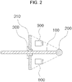
- FIG. 2 is a conceptual diagram illustrating a tube weld X-ray inspection device according to another embodiment of the present disclosure.
- FIG. 3 is a conceptual diagram illustrating a tube weld X-ray inspection device according to still another embodiment of the present disclosure.
- FIG. 4 is a conceptual diagram illustrating a tube weld X-ray inspection device according to yet still another embodiment of the present disclosure.
- FIG. 1 is a conceptual diagram illustrating a tube weld X-ray inspection device according to an embodiment of the present disclosure.
- FIG. 1 shows that an X-ray source is inserted into a tube so that the tube weld X-ray inspection device according to the embodiment of the present disclosure inspects a welding part located at an inlet side of the tube.
- the tube weld X-ray inspection device includes an X-ray support 100, an X-ray source 200, and an IP (Image Plate) fixing part 300.
- the X-ray support 100 is formed in a length direction so that the X-ray support 100 is inserted into the tube 10.
- the X-ray support 100 is for inserting the X-ray source 200 into the tube, and any shape capable of being inserted into the tube may be applied, for example, the X-ray support 100 is formed in a rod shape.
- the X-ray source 200 is provided at a side of the X-ray support 100 in the length direction thereof, and emits X-rays.
- the X-ray source 200 is for being inserted into the tube and emitting X-rays to the inlet side of the tube (the direction from which the X-ray source 200 enters), that is, a welding part 30 between the tube 10 and a tube sheet 20.
- a welding part 30 between the tube 10 and a tube sheet 20.
- the IP fixing part 300 is for fixing an image plate 310 in a direction perpendicular to the axis of the length direction of the X-ray support 100 while being spaced a predetermined distance apart from the X-ray source 200.
- the image plate 310 absorbs X-rays and stores the X-rays in the form of energy.
- the image plate 310 is a plate coated with a photo-stimulable fluorescent material.
- the image plate 310 absorbs the X-rays with which the image plate 310 is irradiated and stores the X-rays in the form of energy, and then when the image plate 310 is irradiated with irradiation light such as red light, signal light, such as blue light, in a particular color diverges.
- the image plate 310 stores information obtained by an X-ray photographing device, in the form of energy in the image plate 310.
- the signal light when the image plate 310 is irradiated with the irradiation light in a particular color, such as red light, the signal light, such as blue light, diffuses and diverges from the irradiated point in all directions.
- the diverging particular color may transfer image information, so is called signal light.
- the IP fixing part 300 may be realized in various ways as long as the IP fixing part 300 can fix the image plate 310 to a predetermined location.
- the image plate 310 itself may be the IP fixing part 300.
- the IP fixing part 300 may be realized in various ways, for example, the image plate 310 of a cartridge type is made to be replaceable in a fixed state, and only the image plate 310 is made to be replaceable.
- the reason why the IP fixing part 300 is replaceable is that the image plate 310 is a consumable material, and in order to enable various applications, such as the size of the image plate 310 being changed according to the size of the tube.
- the IP fixing part 300 of the tube weld X-ray inspection device is movable in the length direction of the X-ray support 100 along the X-ray support 100.
- the IP fixing part 300 of the tube weld X-ray inspection device enables the image plate 310 to be attached and detached.
- the IP fixing part 300 may be formed in a shape supporting the image plate 310 from the rear (see FIG. 1 ).
- the IP fixing part 300 may be formed in a shape (a casing shape) surrounding the image plate 310 (not shown).
- the portion surrounding the front of the image plate 310 is made of a material, for example, a transparent material, which does not seriously interrupt the progress of X-rays.
- the image plate 310 of the tube weld X-ray inspection device is formed in a shape of a plate with a hollow center.
- the image plate 310 may have a hollow so that the axis portion of the length direction of the X-ray support 100 is inserted through the hollow portion of the image plate 310 and the image plate 310 is fixed.
- the image plate 310 When the image plate 310 is not formed as a single integrated piece and several attached plates are used as the image plate 310, it is undesirable because image loss or image distortion may occur at the seam portion.
- the image plate 310 is formed in a shape corresponding to the outer diameter of the tube and that the hollow in the image plate 310 is formed in a shape corresponding to the outer diameter of the X-ray support 100.
- the image plate 310 is formed in a donut shape.
- FIG. 2 is a conceptual diagram illustrating a tube weld X-ray inspection device according to another embodiment of the present disclosure.
- FIG. 2 shows the embodiment in which a reader, an initialization module, or both a reader and an initialization module are added to the form in FIG. 1 .
- the tube weld X-ray inspection device may include a reader 800 that irradiates the image plate 310 with irradiation light, and receives signal light diverging from the image plate 310 to convert the signal light into information in the form of an image.
- the reader 800 irradiates the image plate 310 with irradiation light required to obtain image information stored in the image plate 310, a light receiving element receives the signal light diverging from the image plate 310, and the light receiving element converts the received signal light into an electrical signal to generate image information.
- a filter that passes only the signal light is provided between the image plate 310 and the light receiving element.
- the irradiation light infrared light or light in a red light wavelength range may be used, and as the signal light, ultraviolet light or light in a blue light wavelength range may be used.
- the signal light diverging from the image plate 310 laminated with a barium-based mixture and resin is blue light, so when a blue color filter is used, the signal light passes through the filter, and the irradiation light and the ambient light coming from outside are blocked by the filter, thereby reducing image distortion caused by the irradiation light or the ambient light other than the signal light in obtaining an image.
- the filter is for obtaining light, mainly, excitation light.
- excitation light in a wavelength range from ultraviolet light to blue light (about 500 nm) or lower is absorbed and irradiation light in a higher range is blocked.
- the light receiving element is at least one selected from the group of a photodiode (PD) or avalanche photodiode (APD), a multi-pixel photon counter (MPPC), and a photomultiplier tube (PMD) that convert signal light into electrical signals. Any other light receiving elements having a function of converting light into an electrical signal may be used.
- PD photodiode
- APD avalanche photodiode
- MPPC multi-pixel photon counter
- PMD photomultiplier tube
- the multi-pixel photon counter is also called a silicon photomultiplier (SiPM), and Geiger-mode avalanche photodiodes are provided in an array.
- a process for obtaining an X-ray image by the tube weld X-ray inspection device is as follows.
- An image plate is mounted and X-rays are emitted >> the emited X-rays are stored as energy in the image plate >> the image plate is irradiated with irradiation light (e.g., laser beams) by the reader >> the energy stored in the image plate is emitted as signal light >> the obtained signal light signal is converted into a digital signal by the reader >> through image processing, one digital X-ray image is completed
- the X-ray energy remaining in the image plate is removed by irradiating the image plate with light, so that the image plate is used repeatedly.
- waste is reduced in terms of environment and cost.
- CR computed radiography
- an image plate is reusable, and since information is obtained using X-rays with which the image plate is directly irradiated, if an appropriate imaging process is performed, a clearer image can be obtained than when a film is used.
- a darkroom required for an existing film-screen detector is not required, so that an inspector is able to conduct inspection more conveniently.
- the reader 800 obtains information in the form of an image.
- the X-ray support 100 is fixed has been described above as an example, but the present disclosure is not limited thereto and various applications, such as the X-ray support 100 being rotatable, are possible.
- the reader 800 of the tube weld X-ray inspection device moves to the outside of the region for the image plate 310 before X-ray photography, and moves to the position at which image information of the image plate 310 is extractable, after X-ray photography.
- the region for the image plate 310 refers to a region in which the X-rays emitted from the X-ray source 200 reach the image plate 310.
- the region for the image plate 310 is an inside region of the dotted line.
- the outside of the region for the image plate 310 refers to a region (the outside of the dotted line) (which does not intercept the X-rays) in which the X-rays emitted from the X-ray source 200 are not interrupted until the X-rays reach the image plate 310.
- FIG. 2 shows that the reader 800 is movable only in an upward-downward direction, but the present disclosure is not limited thereto.
- the reader 800 can move so as not to interrupt photographing during X-ray photography, for example, move in an upward-downward direction and then in a forward-backward direction, and can move to the position at which image information of the image plate 310 is extractable so as to obtain an image after X-ray photography.
- FIG. 2 shows that ahead of the image plate 310, the reader 800 moves to the position at which image information of the image plate 310 is extractable, but the present disclosure is not limited thereto. Various applications are possible as long as the image information can be extracted from the image plate 310, for example, behind the image plate 310, the reader 800 moves to the position at which the image information of the image plate 310 is extractable.
- the tube weld X-ray inspection device may include an initialization module 900 that irradiates the image plate 310 with light to make the image plate 310 be in a re-photographable state.
- the initialization module 900 is for initializing the energy stored in the image plate 310, and removes the energy remaining in the image plate 310 by irradiating the image plate 310 with light.
- the initialization module 900 makes the image plate 310 be in the re-photographable state.
- the image plate 310 is rotated and the initialization module 900 is fixed
- the initialization module 900 is fixed at the X-ray support 100
- the X-ray support 100 is fixed and thus the initialization module 900 is fixed
- the image plate 310 is rotated on the X-ray support 100.
- the initialization module 900 is rotated and the image plate 310 is fixed, when the image plate 310 is fixed at the X-ray support 100, the X-ray support 100 is fixed and thus the image plate 310 is fixed, and the initialization module 900 is rotated around the X-ray support 100.
- the X-ray support 100 is fixed has been described above as an example, but the present disclosure is not limited thereto and various applications, such as the X-ray support 100 being rotatable, are possible.
- the initialization module 900 of the tube weld X-ray inspection device moves to the outside of the region for the image plate 310 before X-ray photography, and moves to the position at which the image plate 310 can be made to be in the re-photographable state after X-ray photography.
- the region for the image plate 310 refers to a region in which the X-rays emitted from the X-ray source 200 reach the image plate 310.
- the region for the image plate 310 is an inside region of the dotted line.
- the outside of the region for the image plate 310 refers to a region (the outside of the dotted line) (which does not intercept the X-rays) in which the X-rays emitted from the X-ray source 200 are not interrupted until the X-rays reach the image plate 310.
- the example in FIG. 2 shows that the initialization module 900 is movable only in an upward-downward direction, but the present disclosure is not limited thereto.
- the initialization module 900 can move so as not to interrupt photographing during X-ray photography, for example, move in an upward-downward direction and then in a forward-backward direction, and can move to the position at which the image plate 310 can be made to be in the re-photographable state so as to initialize the image plate 310.
- FIG. 2 shows that ahead of the image plate 310, the initialization module 900 moves to the position at which the image plate 310 can be made to be in the re-photographable state, but the present disclosure is not limited thereto.
- the initialization module 900 moves to the position at which the image plate 310 can be made to be in the re-photographable state.
- FIG. 3 is a conceptual diagram illustrating a tube weld X-ray inspection device according to an embodiment of the present disclosure.
- FIG. 3 shows that an X-ray source is inserted into a tube so that the tube weld X-ray inspection device according to the embodiment of the present disclosure inspects a welding part located at an inlet side of the tube.
- the tube weld X-ray inspection device includes an X-ray support 100, an X-ray source 200, and IP fixing parts 300.
- the X-ray support 100 is formed in a length direction so that the X-ray support 100 is inserted into the tube 10.
- the X-ray support 100 is for inserting the X-ray source 200 into the tube, and any shape capable of being inserted into the tube may be applied, for example, the X-ray support 100 is formed in a rod shape.
- the X-ray source 200 is provided at a side of the X-ray support 100 in the length direction thereof, and emits X-rays.
- the X-ray source 200 is for being inserted into the tube and emitting X-rays to the inlet side of the tube (the direction from which the X-ray source 200 enters), that is, a welding part 30 between the tube 10 and a tube sheet 20.
- a welding part 30 between the tube 10 and a tube sheet 20.
- the IP fixing parts 300 are for fixing respective image plates 310 in a direction perpendicular to the axis of the length direction of the X-ray support 100 while being spaced respective predetermined distances apart from the X-ray source 200.
- the image plates 310 absorb X-rays and store the X-rays in the form of energy.
- a plurality of the IP fixing parts 300 are provided such that the plurality of the IP fixing parts 300 are spaced apart from each other by a predetermined distance.
- Each of the image plates 310 is a plate coated with a photo-stimulaible fluorescent material.
- the image plates 310 absorb the X-rays with which the image plates 310 are irradiated and store the X-rays in the form of energy, and then when the image plates 310 are irradiated with irradiation light such as red light, signal light, such as blue light, in a particular color diverges.
- the image plates 310 store information obtained by an X-ray photographing device, in the form of energy in the image plates 310.
- the signal light such as blue light
- the diverging particular color may transfer image information, so is called signal light.
- the IP fixing parts 300 may be realized in various ways as long as the IP fixing parts 300 can fix the image plates 310 to predetermined locations.
- the image plates 310 themselves can be fixed at user-desiring locations on the axis of the length direction of the X-ray support 100, the image plates 310 themselves may be the IP fixing parts 300.
- the IP fixing parts 300 may be realized in various ways, for example, the image plates 310 of a cartridge type are made to be replaceable in a fixed state, and only the image plates 310 are made to be replaceable.
- IP fixing parts 300 are replaceable.
- the image plates 310 are a consumable material, and in order to enable various applications, such as the sizes of the image plates 310 being changed according to the size of the tube.
- the IP fixing parts 300 are for more accurate measurement.
- the IP fixing parts 300 are made of a material through which some of the X-rays can pass.
- the tube weld X-ray inspection device can take n (n is a natural number equal to or greater than 2) images simultaneously by performing one X-ray photography, and combines the n images obtained from the n image plates 310 photographed in that way, so that a three-dimensional image highlighting a problem portion can be obtained.
- the IP fixing parts 300 of the tube weld X-ray inspection device are movable in the length direction of the X-ray support 100 along the X-ray support 100.
- the IP fixing parts 300 of the tube weld X-ray inspection device enable the image plates 310 to be attached and detached.
- the IP fixing parts 300 may be formed in a shape supporting the respective image plates 310 from the rear (see FIG. 3 ).
- the IP fixing parts 300 may be formed in a shape (a casing shape) surrounding the respective image plates 310 (not shown).
- the portion surrounding the front of each of the image plates 310 is made of a material, for example, a transparent material, which does not seriously interrupt the progress of X-rays.
- each of the image plates 310 of the tube weld X-ray inspection device is formed in a shape of a plate with a hollow center.
- Each image plate 310 may have a hollow so that the axis portion of the length direction of the X-ray support 100 is inserted through the hollow portion of each image plate 310 and each image plate 310 is fixed.
- each image plate 310 is not formed as a single integrated piece and several attached plates are used as each image plate 310, it is undesirable because image loss or image distortion may occur at the seam portion.
- each image plate 310 is formed in a shape corresponding to the outer diameter of the tube and that the hollow in each image plate 310 is formed in a shape corresponding to the outer diameter of the X-ray support 100.
- the image plates 310 are formed in a donut shape.
- FIG. 4 is a conceptual diagram illustrating a tube weld X-ray inspection device according to yet still another embodiment of the present disclosure.
- FIG. 4 shows the embodiment in which readers, initialization modules, or readers and initialization modules are added to the form in FIG. 3 .
- the tube weld X-ray inspection device may include readers 800 that irradiate the respective image plates 310 with irradiation light, and receive signal light diverging from the image plates 310 to convert the signal light into information in the form of an image.
- the readers 800 irradiate the image plates 310 with irradiation light required to obtain image information stored in the image plates 310, light receiving elements receive the signal light diverging from the image plates 310, and the light receiving elements convert the received signal light into electrical signals to generate image information.
- filters that pass only the signal light are provided between the image plates 310 and the light receiving elements.
- the irradiation light infrared light or light in a red light wavelength range may be used, and as the signal light, ultraviolet light or light in a blue light wavelength range may be used.
- the signal light diverging from the image plates 310 laminated with a barium-based mixture and resin is blue light, so when blue color filters are used, the signal light passes through the filters, and the irradiation light and the ambient light coming from outside are blocked by the filters, thereby reducing image distortion caused by the irradiation light or the ambient light other than the signal light in obtaining an image.
- Each of the filters is for obtaining light, mainly, excitation light.
- the signal light is blue light and blue color filters are used, excitation light in a wavelength range from ultraviolet light to blue light (about 500 nm) or lower is absorbed and irradiation light in a higher range is blocked.
- the light receiving elements are at least one selected from the group of a photodiode (PD) or avalanche photodiode (APD), a multi-pixel photon counter (MPPC), and a photomultiplier tube (PMD) that convert signal light into electrical signals. Any other light receiving elements having a function of converting light into an electrical signal may be used.
- PD photodiode
- APD avalanche photodiode
- MPPC multi-pixel photon counter
- PMD photomultiplier tube
- the multi-pixel photon counter is also called a silicon photomultiplier (SiPM), and Geiger-mode avalanche photodiodes are provided in an array.
- a process for obtaining an X-ray image by the tube weld X-ray inspection device is as follows.
- Image plates are mounted and X-rays are emitted >> the emited X-rays are stored as energy in the image plates >> the image plates are irradiated with irradiation light (e.g., laser beams) by the readers >> the energy stored in the image plates is emitted as signal light >> the obtained signal light signals are converted into digital signals by the readers >> through image processing, one digital X-ray image is completed
- the X-ray energy remaining in the image plates is removed by irradiating the image plates with light, so that the image plates are used repeatedly.
- waste is reduced in terms of environment and cost.
- CR computed radiography
- an image plate is reusable, and since information is obtained using X-rays with which the image plate is directly irradiated, if an appropriate imaging process is performed, a clearer image can be obtained than when a film is used.
- a darkroom required for an existing film-screen detector is not required, so that an inspector is able to conduct inspection more conveniently.
- the readers 800 obtain information in the form of an image.
- the X-ray support 100 is fixed has been described above as an example, but the present disclosure is not limited thereto and various applications, such as the X-ray support 100 being rotatable, are possible.
- the readers 800 of the tube weld X-ray inspection device move to the outside of the region for the image plates 310 before X-ray photography, and move to the positions at which image information of the image plates 310 is extractable, after X-ray photography.
- the region for the image plates 310 refers to a region in which the X-rays emitted from the X-ray source 200 reach the image plates 310.
- the region for the image plates 310 is an inside region of the dotted line.
- the outside of the region for the image plates 310 refers to a region (the outside of the dotted line) (which does not intercept the X-rays) in which the X-rays emitted from the X-ray source 200 are not interrupted until the X-rays reach the image plates 310.
- each reader 800 is movable only in an upward-downward direction, but the present disclosure is not limited thereto.
- Various applications are possible as long as each reader 800 can move so as not to interrupt photographing during X-ray photography, for example, move in an upward-downward direction and then in a forward-backward direction, and can move to the position at which image information of the matched image plate 310 is extractable so as to obtain an image after X-ray photography.
- each reader 800 moves to the position at which image information of the matched image plate 310 is extractable, but the present disclosure is not limited thereto.
- Various applications are possible as long as the image information can be extracted from the matched image plate 310, for example, behind the matched image plate 310, each reader 800 moves to the position at which the image information of the matched image plate 310 is extractable.
- the tube weld X-ray inspection device may include initialization modules 900 that irradiate the respective image plates 310 with light to make the image plates 310 be in a re-photographable state.
- the initialization modules 900 are for initializing the energy stored in the image plates 310, and remove the energy remaining in the image plates 310 by irradiating the image plates 310 with light.
- the initialization modules 900 make the image plate 310 be in the re-photographable state.
- the initialization modules 900 are rotated and the image plates 310 are fixed
- the X-ray support 100 is fixed and thus the image plates 310 are fixed
- the initialization modules 900 are rotated around the X-ray support 100.
- the X-ray support 100 is fixed has been described above as an example, but the present disclosure is not limited thereto and various applications, such as the X-ray support 100 being rotatable, are possible.
- the initialization modules 900 of the tube weld X-ray inspection device move to the outside of the region for the image plates 310 before X-ray photography, and move to the positions at which the image plates 310 can be made to be in the re-photographable state after X-ray photography.
- the region for the image plates 310 refers to a region in which the X-rays emitted from the X-ray source 200 reach the image plates 310.
- the region for the image plates 310 is an inside region of the dotted line.
- the outside of the region for the image plates 310 refers to a region (the outside of the dotted line) (which does not intercept the X-rays) in which the X-rays emitted from the X-ray source 200 are not interrupted until the X-rays reach the image plates 310.
- each initialization module 900 is movable only in an upward-downward direction, but the present disclosure is not limited thereto.
- Various applications are possible as long as each initialization module 900 can move so as not to interrupt photographing during X-ray photography, for example, move in an upward-downward direction and then in a forward-backward direction, and can move to the position at which the matched image plate 310 can be made to be in the re-photographable state so as to initialize the matched image plate 310.
- each initialization module 900 moves to the position at which the image plate 310 can be made to be in the re-photographable state, but the present disclosure is not limited thereto.
- Various applications are possible as long as the matched image plate 310 can be made to be in the re-photographable state, for example, behind the matched image plate 310, each initialization module 900 moves to the position at which the matched image plate 310 can be made to be in the re-photographable state.
Landscapes
- Health & Medical Sciences (AREA)
- Life Sciences & Earth Sciences (AREA)
- Physics & Mathematics (AREA)
- General Physics & Mathematics (AREA)
- Chemical & Material Sciences (AREA)
- Analytical Chemistry (AREA)
- Biochemistry (AREA)
- General Health & Medical Sciences (AREA)
- Immunology (AREA)
- Pathology (AREA)
- Engineering & Computer Science (AREA)
- Toxicology (AREA)
- High Energy & Nuclear Physics (AREA)
- Molecular Biology (AREA)
- Spectroscopy & Molecular Physics (AREA)
- Multimedia (AREA)
- Nuclear Medicine, Radiotherapy & Molecular Imaging (AREA)
- Radiology & Medical Imaging (AREA)
- Food Science & Technology (AREA)
- Medicinal Chemistry (AREA)
- Analysing Materials By The Use Of Radiation (AREA)
Abstract
Description
- The present application claims priorities to
Korean Patent Application Nos. 10-2021-0041440 10-2021-0041442, filed March 30, 2021 - The present disclosure relates to a tube weld X-ray inspection device. More particularly, the present disclosure relates to a tube weld X-ray inspection device for inspecting an abnormality, such as a tube welding part crack, of a heat exchanger by using X-rays.
- A shell and tube heat exchanger is a typical heat exchanger, and is composed of two tube sheets and multiple tubes connecting the two tube sheets, and the outside thereof is a cylindrical shell having a airtight structure. The shell and tube heat exchanger is used for various types of heat exchange, such as heating, cooling, condensation, vaporization, etc.
- As a fluid flows into and out of the tubes and a different fluid flows into and out of the space outside the tubes, heat exchange is made between the fluids. In general, as the fluid flowing into the space outside the tubes, a fluid, for example, water, or seawater, at room temperature is used.
- As the fluid flowing into the tubes, gas is used. However, no limitation thereto is imposed.
- Outside the tubes, multiple baffle plates may be formed to form a zigzag flow path of the fluid.
- The tube sheets have multiple insertion holes formed therein. With the tubes inserted in the respective insertion holes of the tube sheets, the connection parts of the tubes and the tube sheets are jointed by welding, so that the fluid inside the tubes and the fluid outside the tubes are prevented from mixing. That is, the fluids are prevented from permeating (leaking) between the tubes and the tube sheets.
- For devices, for example, a shell and tube heat exchanger, in which multiple tubes are joined by welding, it is necessary to inspect seam portions.
- In pipes connected by welding, welds are formed. When connection parts of the pipes are melted and welded, such welds are melted and cooled and thus the structures are recrystallized. Therefore, the welds are weaker in strength than other parts of the pipes.
- In addition, welds vary in welding state according to a worker's skill. For example, if the welding time is too long or short, the weld is not strong. Alternatively, if there are many pores or impurities in the weld, the strength is significantly weak.
- If the weld, which itself is weaker in strength than other parts, is made to be weaker by the work of an unskilled person or external influences, such as existence of pores or impurities, a crack may appear in a short time in use and the fluid may leak through the weld. If such crack proceeds for a long time, the weld is finally damaged and the pipe in use loses its function.
- Therefore, before being buried and used, the welded pipes are inspected for various safety levels including strength, by using an inspection device.
-
Korean Patent Application Publication No. 10-1984-0002103 - The foregoing is intended merely to aid in the understanding of the background of the present disclosure, and is not intended to mean that the present disclosure falls within the purview of the related art that is already known to those skilled in the art.
- (Patent Document 1)
Korean Patent Application Publication No. 10-1984-0002103 (Publication date: 11 June 1984 - Accordingly, the present disclosure has been made keeping in mind the above problems occurring in the related art, and the present disclosure is directed to providing a tube weld X-ray inspection device for inspecting an abnormality, such as a tube welding part crack, of a heat exchanger by using X-rays.
- The objective of the embodiments of the present disclosure is not limited to the above-described objective, and other objectives which are not described herein will be come apparent to those skilled in the art from the following description.
- According to an embodiment of the present disclosure, there is provided a tube weld X-ray inspection device including: an X-ray support provided in a length direction so that the X-ray support is inserted into a tube; an X-ray source provided at a side of the X-ray support in the length direction thereof, and emitting X-rays; and an IP (Image Plate) fixing part for fixing an image plate in a direction perpendicular to an axis of the length direction of the X-ray support while being spaced a predetermined distance from the X-ray source, the image plate absorbing the X-rays and storing the X-rays in a form of energy.
- According to the embodiment of the present disclosure, the tube weld X-ray inspection device can easily inspect abnormality of a welding part, such as a tube welding part crack, of a heat exchanger by using X-rays.
- In addition, a three-dimensional image highlighting a problem portion can be obtained.
- In addition, as the IP fixing part is movable along the X-ray support, it is easy to adjust the depth at which the X-ray source is inserted into the tube.
- In addition, because the image plate is attachable and detachable, the image plate can be applied variably depending on a measurement target, so that tube welding parts in various sizes can be inspected.
- In addition, the image plate is provided in a shape of a plate with a hollow center, so that it is easy to replace the image plate and move the image plate along the X-ray support.
- In addition, by using the image plate in a single integrated piece, image loss or image distortion can be prevented from occurring at the seam portion.
- In addition, by providing a reader, there is no need to take the image plate apart to obtain an image, thus reducing a re-photographing time.
- In addition, while either the image plate or the reader is rotated and the other is fixed, the reader obtains information of the image plate, so that there is no need to take apart and insert the image plate, thus reducing an image acquisition time.
- In addition, the reader is moved to appropriate positions before and after X-ray photograph, so that a re-photographing time can be reduced.
- In addition, by providing an initialization module, there is no need to take the image plate apart to initialize the image plate, thus reducing a re-photographing time.
- In addition, while either the image plate or the initialization module is rotated and the other is fixed, the initialization module initializes the image plate, so that there is no need to take apart and insert the image plate, thus reducing a re-photographing time.
- In addition, the initialization module is moved to appropriate positions before and after X-ray photography, so that a re-photographing time can be reduced.
- The above and other objectives, features, and other advantages of the present disclosure will be more clearly understood from the following detailed description when taken in conjunction with the accompanying drawings, in which:
-
FIG. 1 is a conceptual diagram illustrating a tube weld X-ray inspection device according to an embodiment of the present disclosure; -
FIG. 2 is a conceptual diagram illustrating a tube weld X-ray inspection device according to another embodiment of the present disclosure; -
FIG. 3 is a conceptual diagram illustrating a tube weld X-ray inspection device according to still another embodiment of the present disclosure; and -
FIG. 4 is a conceptual diagram illustrating a tube weld X-ray inspection device according to yet still another embodiment of the present disclosure. - The present disclosure may be modified in various ways and implemented by various embodiments, so that specific embodiments are shown in the drawings and will be described in detail. However, the present disclosure is not limited thereto, and the exemplary embodiments can be construed as including all modifications, equivalents, or substitutes in a technical concept and a technical scope of the present disclosure.
- It will be understood that when an element is referred to as being coupled or connected to another element, it can be directly coupled or connected to the other element or intervening elements may be present therebetween.
- In contrast, it will be understood that when an element is referred to as being "directly coupled" or "directly connected" to another element, there are no intervening elements present.
- The terms used in the present specification are merely used to describe particular embodiments, and are not intended to limit the present disclosure. As used herein, the singular forms "a", "an", and "the" are intended to include the plural forms as well, unless the context clearly indicates otherwise. In the present specification, it is to be understood that terms such as "including", "having", etc. are intended to indicate the existence of the features, numbers, processes, actions, elements, parts, or combinations thereof disclosed in the specification, and are not intended to preclude the possibility that one or more other features, numbers, processes, actions, elements, parts, or combinations thereof may exist or may be added.
- Unless otherwise defined, all terms including technical and scientific terms used herein have the same meaning as commonly understood by those skilled in the art to which the present disclosure pertains. It will be further understood that terms used herein should be interpreted as having a meaning that is consistent with their meaning in the context of this specification and the relevant art and will not be interpreted in an idealized or overly formal sense unless expressly so defined herein.
- Hereinafter, the present disclosure will be described in more detail with reference to the accompanying drawings. Prior to offering the description, the terms or words used in the present specification and claims should not be interpreted as being limited to typical meanings or dictionary definitions, but should be interpreted as having meanings and concepts relevant to the technical scope of the present disclosure based on the rule according to which an inventor can appropriately define the concept of the term to describe most appropriately the best method he or she knows for carrying out the disclosure. In addition, unless otherwise defined, technical and scientific terms used herein have the same meaning as commonly understood by those skilled in the art to which the present disclosure pertains. In the following description and the accompanying drawings, descriptions of known functions and components that make the gist of the present disclosure unclear will be omitted. The drawings exemplified below are provided as examples so that the idea of the present disclosure can be sufficiently transferred to those skilled in the art to which the present disclosure pertains. Therefore, the present disclosure is not limited to the accompanying drawings and may be embodied in other forms. In addition, the same reference numerals refer to the same elements throughout the specification. It is noted that the same elements in the drawings are denoted by the same reference numerals throughout the drawings, if possible.
-
FIG. 1 is a conceptual diagram illustrating a tube weld X-ray inspection device according to an embodiment of the present disclosure.FIG. 2 is a conceptual diagram illustrating a tube weld X-ray inspection device according to another embodiment of the present disclosure.FIG. 3 is a conceptual diagram illustrating a tube weld X-ray inspection device according to still another embodiment of the present disclosure.FIG. 4 is a conceptual diagram illustrating a tube weld X-ray inspection device according to yet still another embodiment of the present disclosure. -
FIG. 1 is a conceptual diagram illustrating a tube weld X-ray inspection device according to an embodiment of the present disclosure.FIG. 1 shows that an X-ray source is inserted into a tube so that the tube weld X-ray inspection device according to the embodiment of the present disclosure inspects a welding part located at an inlet side of the tube. - As shown in
FIG. 1 , the tube weld X-ray inspection device according to the embodiment of the present disclosure includes anX-ray support 100, anX-ray source 200, and an IP (Image Plate) fixingpart 300. - The
X-ray support 100 is formed in a length direction so that theX-ray support 100 is inserted into thetube 10. - The
X-ray support 100 is for inserting theX-ray source 200 into the tube, and any shape capable of being inserted into the tube may be applied, for example, theX-ray support 100 is formed in a rod shape. - The
X-ray source 200 is provided at a side of theX-ray support 100 in the length direction thereof, and emits X-rays. - The
X-ray source 200 is for being inserted into the tube and emitting X-rays to the inlet side of the tube (the direction from which theX-ray source 200 enters), that is, awelding part 30 between thetube 10 and atube sheet 20. As long as X-rays can be emitted to thewelding part 30 located at the inlet side of thetube 10, various applications, such as omnidirectional radiation and directional radiation, are possible. - The
IP fixing part 300 is for fixing animage plate 310 in a direction perpendicular to the axis of the length direction of theX-ray support 100 while being spaced a predetermined distance apart from theX-ray source 200. Theimage plate 310 absorbs X-rays and stores the X-rays in the form of energy. - The
image plate 310 is a plate coated with a photo-stimulable fluorescent material. Theimage plate 310 absorbs the X-rays with which theimage plate 310 is irradiated and stores the X-rays in the form of energy, and then when theimage plate 310 is irradiated with irradiation light such as red light, signal light, such as blue light, in a particular color diverges. - That is, the
image plate 310 stores information obtained by an X-ray photographing device, in the form of energy in theimage plate 310. - Herein, when the
image plate 310 is irradiated with the irradiation light in a particular color, such as red light, the signal light, such as blue light, diffuses and diverges from the irradiated point in all directions. Herein, the diverging particular color may transfer image information, so is called signal light. - The
IP fixing part 300 may be realized in various ways as long as theIP fixing part 300 can fix theimage plate 310 to a predetermined location. - For example, if the
image plate 310 itself can be fixed at a user-desiring location on the axis of the length direction of theX-ray support 100, theimage plate 310 itself may be theIP fixing part 300. - The
IP fixing part 300 may be realized in various ways, for example, theimage plate 310 of a cartridge type is made to be replaceable in a fixed state, and only theimage plate 310 is made to be replaceable. - The reason why the
IP fixing part 300 is replaceable is that theimage plate 310 is a consumable material, and in order to enable various applications, such as the size of theimage plate 310 being changed according to the size of the tube. - As shown in
FIG. 1 , theIP fixing part 300 of the tube weld X-ray inspection device according to the embodiment of the present disclosure is movable in the length direction of theX-ray support 100 along theX-ray support 100. - This is to adjust the location of the
IP fixing part 300 when necessary, for example, adjusting the location of theIP fixing part 300 depending on the depth of insertion of theX-ray source 200 into thetube 10, so that more various measurement targets are measured. - As shown in
FIG. 1 , theIP fixing part 300 of the tube weld X-ray inspection device according to the embodiment of the present disclosure enables theimage plate 310 to be attached and detached. - The
IP fixing part 300 may be formed in a shape supporting theimage plate 310 from the rear (seeFIG. 1 ). - Alternatively, the
IP fixing part 300 may be formed in a shape (a casing shape) surrounding the image plate 310 (not shown). Herein, it is preferable that the portion surrounding the front of the image plate 310 (theX-ray source 200 side) is made of a material, for example, a transparent material, which does not seriously interrupt the progress of X-rays. - As shown in
FIG. 1 , theimage plate 310 of the tube weld X-ray inspection device according to the embodiment of the present disclosure is formed in a shape of a plate with a hollow center. - The
image plate 310 may have a hollow so that the axis portion of the length direction of theX-ray support 100 is inserted through the hollow portion of theimage plate 310 and theimage plate 310 is fixed. - This is to facilitate the movement along the
X-ray support 100 because theimage plate 310 is a consumable material, and also to store the X-rays that have passed through thewelding part 30 of thetube 10, in the form of energy in theimage plate 310 formed in a single integrated piece. - When the
image plate 310 is not formed as a single integrated piece and several attached plates are used as theimage plate 310, it is undesirable because image loss or image distortion may occur at the seam portion. - Therefore, it is preferable that the
image plate 310 is formed in a shape corresponding to the outer diameter of the tube and that the hollow in theimage plate 310 is formed in a shape corresponding to the outer diameter of theX-ray support 100. - For example, when the outer diameter of the tube is circular and the outer diameter of the
X-ray support 100 is circular, theimage plate 310 is formed in a donut shape. -
FIG. 2 is a conceptual diagram illustrating a tube weld X-ray inspection device according to another embodiment of the present disclosure.FIG. 2 shows the embodiment in which a reader, an initialization module, or both a reader and an initialization module are added to the form inFIG. 1 . - As shown in
FIG. 2 , the tube weld X-ray inspection device according to the embodiment of the present disclosure may include areader 800 that irradiates theimage plate 310 with irradiation light, and receives signal light diverging from theimage plate 310 to convert the signal light into information in the form of an image. - The
reader 800 irradiates theimage plate 310 with irradiation light required to obtain image information stored in theimage plate 310, a light receiving element receives the signal light diverging from theimage plate 310, and the light receiving element converts the received signal light into an electrical signal to generate image information. - When the irradiation light and the signal light have different wavelength ranges, a filter that passes only the signal light is provided between the
image plate 310 and the light receiving element. - For example, as the irradiation light, infrared light or light in a red light wavelength range may be used, and as the signal light, ultraviolet light or light in a blue light wavelength range may be used.
- The signal light diverging from the
image plate 310 laminated with a barium-based mixture and resin is blue light, so when a blue color filter is used, the signal light passes through the filter, and the irradiation light and the ambient light coming from outside are blocked by the filter, thereby reducing image distortion caused by the irradiation light or the ambient light other than the signal light in obtaining an image. - The filter is for obtaining light, mainly, excitation light. When the signal light is blue light and a blue color filter is used, excitation light in a wavelength range from ultraviolet light to blue light (about 500 nm) or lower is absorbed and irradiation light in a higher range is blocked.
- The light receiving element is at least one selected from the group of a photodiode (PD) or avalanche photodiode (APD), a multi-pixel photon counter (MPPC), and a photomultiplier tube (PMD) that convert signal light into electrical signals. Any other light receiving elements having a function of converting light into an electrical signal may be used.
- The multi-pixel photon counter (MPPC) is also called a silicon photomultiplier (SiPM), and Geiger-mode avalanche photodiodes are provided in an array.
- A process for obtaining an X-ray image by the tube weld X-ray inspection device according to the embodiment of the present disclosure is as follows.
- An image plate is mounted and X-rays are emitted >> the emited X-rays are stored as energy in the image plate >> the image plate is irradiated with irradiation light (e.g., laser beams) by the reader >> the energy stored in the image plate is emitted as signal light >> the obtained signal light signal is converted into a digital signal by the reader >> through image processing, one digital X-ray image is completed
- After the X-ray image is completed in that order, the X-ray energy remaining in the image plate is removed by irradiating the image plate with light, so that the image plate is used repeatedly.
- That is, compared to an analog film that cannot be reused, waste is reduced in terms of environment and cost.
- The above-described method is called computed radiography (CR).
- According to the CR, an image plate is reusable, and since information is obtained using X-rays with which the image plate is directly irradiated, if an appropriate imaging process is performed, a clearer image can be obtained than when a film is used. In addition, a darkroom required for an existing film-screen detector is not required, so that an inspector is able to conduct inspection more conveniently.
- In the tube weld X-ray inspection device according to the embodiment of the present disclosure, as the
image plate 310 is rotated and thereader 800 is fixed, or as thereader 800 is rotated and theimage plate 310 is fixed, thereader 800 obtains information in the form of an image. - In the case in which the
image plate 310 is rotated and thereader 800 is fixed, when thereader 800 is fixed at theX-ray support 100, theX-ray support 100 is fixed and thus thereader 800 is fixed, and theimage plate 310 is rotated on theX-ray support 100. - In the case in which the
reader 800 is rotated and theimage plate 310 is fixed, when theimage plate 310 is fixed at theX-ray support 100, theX-ray support 100 is fixed and thus theimage plate 310 is fixed, and thereader 800 is rotated around theX-ray support 100. - The case in which the
X-ray support 100 is fixed has been described above as an example, but the present disclosure is not limited thereto and various applications, such as theX-ray support 100 being rotatable, are possible. - As shown in
FIG. 2 , thereader 800 of the tube weld X-ray inspection device according to the embodiment of the present disclosure moves to the outside of the region for theimage plate 310 before X-ray photography, and moves to the position at which image information of theimage plate 310 is extractable, after X-ray photography. - The region for the
image plate 310 refers to a region in which the X-rays emitted from theX-ray source 200 reach theimage plate 310. InFIG. 2 , the region for theimage plate 310 is an inside region of the dotted line. - That is, the outside of the region for the
image plate 310 refers to a region (the outside of the dotted line) (which does not intercept the X-rays) in which the X-rays emitted from theX-ray source 200 are not interrupted until the X-rays reach theimage plate 310. - The example in
FIG. 2 shows that thereader 800 is movable only in an upward-downward direction, but the present disclosure is not limited thereto. Various applications are possible as long as thereader 800 can move so as not to interrupt photographing during X-ray photography, for example, move in an upward-downward direction and then in a forward-backward direction, and can move to the position at which image information of theimage plate 310 is extractable so as to obtain an image after X-ray photography. - The example in
FIG. 2 shows that ahead of theimage plate 310, thereader 800 moves to the position at which image information of theimage plate 310 is extractable, but the present disclosure is not limited thereto. Various applications are possible as long as the image information can be extracted from theimage plate 310, for example, behind theimage plate 310, thereader 800 moves to the position at which the image information of theimage plate 310 is extractable. - As shown in
FIG. 2 , the tube weld X-ray inspection device according to the embodiment of the present disclosure may include aninitialization module 900 that irradiates theimage plate 310 with light to make theimage plate 310 be in a re-photographable state. - The
initialization module 900 is for initializing the energy stored in theimage plate 310, and removes the energy remaining in theimage plate 310 by irradiating theimage plate 310 with light. - In the tube weld X-ray inspection device according to the embodiment of the present disclosure, as the
image plate 310 is rotated and theinitialization module 900 is fixed, or as theinitialization module 900 is rotated and theimage plate 310 is fixed, theinitialization module 900 makes theimage plate 310 be in the re-photographable state. - In the case in which the
image plate 310 is rotated and theinitialization module 900 is fixed, when theinitialization module 900 is fixed at theX-ray support 100, theX-ray support 100 is fixed and thus theinitialization module 900 is fixed, and theimage plate 310 is rotated on theX-ray support 100. - In the case in which the
initialization module 900 is rotated and theimage plate 310 is fixed, when theimage plate 310 is fixed at theX-ray support 100, theX-ray support 100 is fixed and thus theimage plate 310 is fixed, and theinitialization module 900 is rotated around theX-ray support 100. - The case in which the
X-ray support 100 is fixed has been described above as an example, but the present disclosure is not limited thereto and various applications, such as theX-ray support 100 being rotatable, are possible. - As shown in
FIG. 2 , theinitialization module 900 of the tube weld X-ray inspection device according to the embodiment of the present disclosure moves to the outside of the region for theimage plate 310 before X-ray photography, and moves to the position at which theimage plate 310 can be made to be in the re-photographable state after X-ray photography. - The region for the
image plate 310 refers to a region in which the X-rays emitted from theX-ray source 200 reach theimage plate 310. InFIG. 2 , the region for theimage plate 310 is an inside region of the dotted line. - That is, the outside of the region for the
image plate 310 refers to a region (the outside of the dotted line) (which does not intercept the X-rays) in which the X-rays emitted from theX-ray source 200 are not interrupted until the X-rays reach theimage plate 310. - The example in
FIG. 2 shows that theinitialization module 900 is movable only in an upward-downward direction, but the present disclosure is not limited thereto. Various applications are possible as long as theinitialization module 900 can move so as not to interrupt photographing during X-ray photography, for example, move in an upward-downward direction and then in a forward-backward direction, and can move to the position at which theimage plate 310 can be made to be in the re-photographable state so as to initialize theimage plate 310. - The example in
FIG. 2 shows that ahead of theimage plate 310, theinitialization module 900 moves to the position at which theimage plate 310 can be made to be in the re-photographable state, but the present disclosure is not limited thereto. Various applications are possible as long as theimage plate 310 can be made to be in the re-photographable state, for example, behind theimage plate 310, theinitialization module 900 moves to the position at which theimage plate 310 can be made to be in the re-photographable state. -
FIG. 3 is a conceptual diagram illustrating a tube weld X-ray inspection device according to an embodiment of the present disclosure.FIG. 3 shows that an X-ray source is inserted into a tube so that the tube weld X-ray inspection device according to the embodiment of the present disclosure inspects a welding part located at an inlet side of the tube. - As shown in
FIG. 3 , the tube weld X-ray inspection device according to the embodiment of the present disclosure includes anX-ray support 100, anX-ray source 200, andIP fixing parts 300. - The
X-ray support 100 is formed in a length direction so that theX-ray support 100 is inserted into thetube 10. - The
X-ray support 100 is for inserting theX-ray source 200 into the tube, and any shape capable of being inserted into the tube may be applied, for example, theX-ray support 100 is formed in a rod shape. - The
X-ray source 200 is provided at a side of theX-ray support 100 in the length direction thereof, and emits X-rays. - The
X-ray source 200 is for being inserted into the tube and emitting X-rays to the inlet side of the tube (the direction from which theX-ray source 200 enters), that is, awelding part 30 between thetube 10 and atube sheet 20. As long as X-rays can be emitted to thewelding part 30 located at the inlet side of thetube 10, various applications, such as omnidirectional radiation and directional radiation, are possible. - The
IP fixing parts 300 are for fixingrespective image plates 310 in a direction perpendicular to the axis of the length direction of theX-ray support 100 while being spaced respective predetermined distances apart from theX-ray source 200. Theimage plates 310 absorb X-rays and store the X-rays in the form of energy. A plurality of theIP fixing parts 300 are provided such that the plurality of theIP fixing parts 300 are spaced apart from each other by a predetermined distance. - Each of the
image plates 310 is a plate coated with a photo-stimulaible fluorescent material. Theimage plates 310 absorb the X-rays with which theimage plates 310 are irradiated and store the X-rays in the form of energy, and then when theimage plates 310 are irradiated with irradiation light such as red light, signal light, such as blue light, in a particular color diverges. - That is, the
image plates 310 store information obtained by an X-ray photographing device, in the form of energy in theimage plates 310. - Herein, when the
image plates 310 are irradiated with the irradiation light in a particular color, such as red light, the signal light, such as blue light, diffuses and diverges from the irradiated points in all directions. Herein, the diverging particular color may transfer image information, so is called signal light. - The
IP fixing parts 300 may be realized in various ways as long as theIP fixing parts 300 can fix theimage plates 310 to predetermined locations. - For example, if the
image plates 310 themselves can be fixed at user-desiring locations on the axis of the length direction of theX-ray support 100, theimage plates 310 themselves may be theIP fixing parts 300. - The
IP fixing parts 300 may be realized in various ways, for example, theimage plates 310 of a cartridge type are made to be replaceable in a fixed state, and only theimage plates 310 are made to be replaceable. - The reason why the
IP fixing parts 300 are replaceable is that theimage plates 310 are a consumable material, and in order to enable various applications, such as the sizes of theimage plates 310 being changed according to the size of the tube. - Providing the plurality of the
IP fixing parts 300 is for more accurate measurement. Herein, it is preferable that theIP fixing parts 300 are made of a material through which some of the X-rays can pass. - The tube weld X-ray inspection device according to the embodiment of the present disclosure can take n (n is a natural number equal to or greater than 2) images simultaneously by performing one X-ray photography, and combines the n images obtained from the
n image plates 310 photographed in that way, so that a three-dimensional image highlighting a problem portion can be obtained. - As shown in
FIG. 3 , theIP fixing parts 300 of the tube weld X-ray inspection device according to the embodiment of the present disclosure are movable in the length direction of theX-ray support 100 along theX-ray support 100. - This is to adjust the locations of the
IP fixing parts 300 when necessary, for example, adjusting the locations of theIP fixing parts 300 depending on the depth of insertion of theX-ray source 200 into thetube 10, so that more various measurement targets are measured. - As shown in
FIG. 3 , theIP fixing parts 300 of the tube weld X-ray inspection device according to the embodiment of the present disclosure enable theimage plates 310 to be attached and detached. - The
IP fixing parts 300 may be formed in a shape supporting therespective image plates 310 from the rear (seeFIG. 3 ). - Alternatively, the
IP fixing parts 300 may be formed in a shape (a casing shape) surrounding the respective image plates 310 (not shown). Herein, it is preferable that the portion surrounding the front of each of the image plates 310 (theX-ray source 200 side) is made of a material, for example, a transparent material, which does not seriously interrupt the progress of X-rays. - As shown in
FIG. 3 , each of theimage plates 310 of the tube weld X-ray inspection device according to the embodiment of the present disclosure is formed in a shape of a plate with a hollow center. - Each
image plate 310 may have a hollow so that the axis portion of the length direction of theX-ray support 100 is inserted through the hollow portion of eachimage plate 310 and eachimage plate 310 is fixed. - This is to facilitate the movement along the
X-ray support 100 because theimage plates 310 are a consumable material, and also to store the X-rays that have passed through thewelding part 30 of thetube 10, in the form of energy in theimage plates 310 each formed in a single integrated piece. - When each
image plate 310 is not formed as a single integrated piece and several attached plates are used as eachimage plate 310, it is undesirable because image loss or image distortion may occur at the seam portion. - Therefore, it is preferable that each
image plate 310 is formed in a shape corresponding to the outer diameter of the tube and that the hollow in eachimage plate 310 is formed in a shape corresponding to the outer diameter of theX-ray support 100. - For example, when the outer diameter of the tube is circular and the outer diameter of the
X-ray support 100 is circular, theimage plates 310 are formed in a donut shape. -
FIG. 4 is a conceptual diagram illustrating a tube weld X-ray inspection device according to yet still another embodiment of the present disclosure.FIG. 4 shows the embodiment in which readers, initialization modules, or readers and initialization modules are added to the form inFIG. 3 . - As shown in
FIG. 4 , the tube weld X-ray inspection device according to the embodiment of the present disclosure may includereaders 800 that irradiate therespective image plates 310 with irradiation light, and receive signal light diverging from theimage plates 310 to convert the signal light into information in the form of an image. - The
readers 800 irradiate theimage plates 310 with irradiation light required to obtain image information stored in theimage plates 310, light receiving elements receive the signal light diverging from theimage plates 310, and the light receiving elements convert the received signal light into electrical signals to generate image information. - When the irradiation light and the signal light have different wavelength ranges, filters that pass only the signal light are provided between the
image plates 310 and the light receiving elements. - For example, as the irradiation light, infrared light or light in a red light wavelength range may be used, and as the signal light, ultraviolet light or light in a blue light wavelength range may be used.
- The signal light diverging from the
image plates 310 laminated with a barium-based mixture and resin is blue light, so when blue color filters are used, the signal light passes through the filters, and the irradiation light and the ambient light coming from outside are blocked by the filters, thereby reducing image distortion caused by the irradiation light or the ambient light other than the signal light in obtaining an image. - Each of the filters is for obtaining light, mainly, excitation light. When the signal light is blue light and blue color filters are used, excitation light in a wavelength range from ultraviolet light to blue light (about 500 nm) or lower is absorbed and irradiation light in a higher range is blocked.
- The light receiving elements are at least one selected from the group of a photodiode (PD) or avalanche photodiode (APD), a multi-pixel photon counter (MPPC), and a photomultiplier tube (PMD) that convert signal light into electrical signals. Any other light receiving elements having a function of converting light into an electrical signal may be used.
- The multi-pixel photon counter (MPPC) is also called a silicon photomultiplier (SiPM), and Geiger-mode avalanche photodiodes are provided in an array.
- A process for obtaining an X-ray image by the tube weld X-ray inspection device according to the embodiment of the present disclosure is as follows.
- Image plates are mounted and X-rays are emitted >> the emited X-rays are stored as energy in the image plates >> the image plates are irradiated with irradiation light (e.g., laser beams) by the readers >> the energy stored in the image plates is emitted as signal light >> the obtained signal light signals are converted into digital signals by the readers >> through image processing, one digital X-ray image is completed
- After the X-ray image is completed in that order, the X-ray energy remaining in the image plates is removed by irradiating the image plates with light, so that the image plates are used repeatedly.
- That is, compared to an analog film that cannot be reused, waste is reduced in terms of environment and cost.
- The above-described method is called computed radiography (CR).
- According to the CR, an image plate is reusable, and since information is obtained using X-rays with which the image plate is directly irradiated, if an appropriate imaging process is performed, a clearer image can be obtained than when a film is used. In addition, a darkroom required for an existing film-screen detector is not required, so that an inspector is able to conduct inspection more conveniently.
- In the tube weld X-ray inspection device according to the embodiment of the present disclosure, as the
image plates 310 are rotated and thereaders 800 are fixed, or as thereaders 800 are rotated and theimage plates 310 are fixed, thereaders 800 obtain information in the form of an image. - In the case in which the
image plates 310 are rotated and thereaders 800 are fixed, when thereaders 800 are fixed at theX-ray support 100, theX-ray support 100 is fixed and thus thereaders 800 are fixed, and theimage plates 310 are rotated on theX-ray support 100. - In the case in which the
readers 800 are rotated and theimage plates 310 are fixed, when theimage plates 310 are fixed at theX-ray support 100, theX-ray support 100 is fixed and thus theimage plates 310 are fixed, and thereaders 800 are rotated around theX-ray support 100. - The case in which the
X-ray support 100 is fixed has been described above as an example, but the present disclosure is not limited thereto and various applications, such as theX-ray support 100 being rotatable, are possible. - As shown in
FIG. 4 , thereaders 800 of the tube weld X-ray inspection device according to the embodiment of the present disclosure move to the outside of the region for theimage plates 310 before X-ray photography, and move to the positions at which image information of theimage plates 310 is extractable, after X-ray photography. - The region for the
image plates 310 refers to a region in which the X-rays emitted from theX-ray source 200 reach theimage plates 310. InFIG. 4 , the region for theimage plates 310 is an inside region of the dotted line. - That is, the outside of the region for the
image plates 310 refers to a region (the outside of the dotted line) (which does not intercept the X-rays) in which the X-rays emitted from theX-ray source 200 are not interrupted until the X-rays reach theimage plates 310. - The example in
FIG. 4 shows that eachreader 800 is movable only in an upward-downward direction, but the present disclosure is not limited thereto. Various applications are possible as long as eachreader 800 can move so as not to interrupt photographing during X-ray photography, for example, move in an upward-downward direction and then in a forward-backward direction, and can move to the position at which image information of the matchedimage plate 310 is extractable so as to obtain an image after X-ray photography. - The example in
FIG. 4 shows that ahead of the matchedimage plate 310, eachreader 800 moves to the position at which image information of the matchedimage plate 310 is extractable, but the present disclosure is not limited thereto. Various applications are possible as long as the image information can be extracted from the matchedimage plate 310, for example, behind the matchedimage plate 310, eachreader 800 moves to the position at which the image information of the matchedimage plate 310 is extractable. - As shown in
FIG. 4 , the tube weld X-ray inspection device according to the embodiment of the present disclosure may includeinitialization modules 900 that irradiate therespective image plates 310 with light to make theimage plates 310 be in a re-photographable state. - The
initialization modules 900 are for initializing the energy stored in theimage plates 310, and remove the energy remaining in theimage plates 310 by irradiating theimage plates 310 with light. - In the tube weld X-ray inspection device according to the embodiment of the present disclosure, as the
image plates 310 are rotated and theinitialization modules 900 are fixed, or as theinitialization modules 900 are rotated and theimage plates 310 are fixed, theinitialization modules 900 make theimage plate 310 be in the re-photographable state. - In the case in which the
image plates 310 are rotated and theinitialization modules 900 are fixed, when theinitialization modules 900 are fixed at theX-ray support 100, theX-ray support 100 is fixed and thus theinitialization modules 900 are fixed, and theimage plates 310 are rotated on theX-ray support 100. - In the case in which the
initialization modules 900 are rotated and theimage plates 310 are fixed, when theimage plates 310 are fixed at theX-ray support 100, theX-ray support 100 is fixed and thus theimage plates 310 are fixed, and theinitialization modules 900 are rotated around theX-ray support 100. - The case in which the
X-ray support 100 is fixed has been described above as an example, but the present disclosure is not limited thereto and various applications, such as theX-ray support 100 being rotatable, are possible. - As shown in
FIG. 4 , theinitialization modules 900 of the tube weld X-ray inspection device according to the embodiment of the present disclosure move to the outside of the region for theimage plates 310 before X-ray photography, and move to the positions at which theimage plates 310 can be made to be in the re-photographable state after X-ray photography. - The region for the
image plates 310 refers to a region in which the X-rays emitted from theX-ray source 200 reach theimage plates 310. InFIG. 4 , the region for theimage plates 310 is an inside region of the dotted line. - That is, the outside of the region for the
image plates 310 refers to a region (the outside of the dotted line) (which does not intercept the X-rays) in which the X-rays emitted from theX-ray source 200 are not interrupted until the X-rays reach theimage plates 310. - The example in
FIG. 4 shows that eachinitialization module 900 is movable only in an upward-downward direction, but the present disclosure is not limited thereto. Various applications are possible as long as eachinitialization module 900 can move so as not to interrupt photographing during X-ray photography, for example, move in an upward-downward direction and then in a forward-backward direction, and can move to the position at which the matchedimage plate 310 can be made to be in the re-photographable state so as to initialize the matchedimage plate 310. - The example in
FIG. 4 shows that ahead of the matchedimage plate 310, eachinitialization module 900 moves to the position at which theimage plate 310 can be made to be in the re-photographable state, but the present disclosure is not limited thereto. Various applications are possible as long as the matchedimage plate 310 can be made to be in the re-photographable state, for example, behind the matchedimage plate 310, eachinitialization module 900 moves to the position at which the matchedimage plate 310 can be made to be in the re-photographable state. - The present disclosure is not limited to the above-described embodiments and has a wide range of application. Various modifications are possible without departing from the substance of the present disclosure set forth in the accompanying claims.
Claims (11)
- A tube weld X-ray inspection device, comprising:an X-ray support provided in a length direction so that the X-ray support is inserted into a tube;an X-ray source provided at a side of the X-ray support in the length direction thereof, and emitting X-rays; andan IP (Image Plate) fixing part for fixing an image plate in a direction perpendicular to an axis of the length direction of the X-ray support while being spaced a predetermined distance from the X-ray source, the image plate absorbing the X-rays and storing the X-rays in a form of energy.
- The tube weld X-ray inspection device of claim 1, wherein a plurality of the IP fixing parts are provided such that the plurality of the IP fixing parts are spaced apart from each other by a predetermined distance.
- The tube weld X-ray inspection device of claim 1 or 2, wherein the IP fixing part is movable in the length direction of the X-ray support along the X-ray support.
- The tube weld X-ray inspection device of claim 1 or 2, wherein the IP fixing part enables the image plate to be attached and detached.
- The tube weld X-ray inspection device of claim 1 or 2, wherein the image plate is provided in a shape of a plate with a hollow center.
- The tube weld X-ray inspection device of claim 1 or 2, further comprising a reader for irradiating the image plate with irradiation light and receiving signal light diverging from the image plate to convert the signal light into information in a form of an image.
- The tube weld X-ray inspection device of claim 6, wherein in the tube weld X-ray inspection device, as the image plate is rotated and the reader is fixed, or as the reader is rotated and the image plate is fixed, the reader obtains the information in the form of the image.
- The tube weld X-ray inspection device of claim 6, wherein the reader moves to an outside of a region for the image plate before X-ray photography, and moves to a position at which image information of the image plate is extractable, after X-ray photography.
- The tube weld X-ray inspection device of claim 6, further comprising an initialization module for irradiating the image plate with light to make the image plate be in a re-photographable state.
- The tube weld X-ray inspection device of claim 9, wherein in the tube weld X-ray inspection device, as the image plate is rotated and the initialization module is fixed, or as the initialization module is rotated and the image plate is fixed, the initialization module makes the image plate be in the re-photographable state.
- The tube weld X-ray inspection device of claim 9, wherein the initialization module moves to an outside of a region for the image plate before X-ray photography, and moves to a position at which the image plate is made to be in the re-photographable state, after X-ray photography.
Applications Claiming Priority (2)
| Application Number | Priority Date | Filing Date | Title |
|---|---|---|---|
| KR1020210041442A KR102303826B1 (en) | 2021-03-30 | 2021-03-30 | Tube welding part x-ray inspection device |
| KR1020210041440A KR102303823B1 (en) | 2021-03-30 | 2021-03-30 | Tube welding part x-ray inspection device |
Publications (2)
| Publication Number | Publication Date |
|---|---|
| EP4067884A1 true EP4067884A1 (en) | 2022-10-05 |
| EP4067884B1 EP4067884B1 (en) | 2025-06-11 |
Family
ID=78621740
Family Applications (1)
| Application Number | Title | Priority Date | Filing Date |
|---|---|---|---|
| EP21208143.4A Active EP4067884B1 (en) | 2021-03-30 | 2021-11-15 | Tube weld x-ray inspection device |
Country Status (3)
| Country | Link |
|---|---|
| US (1) | US11860113B2 (en) |
| EP (1) | EP4067884B1 (en) |
| WO (1) | WO2022211197A1 (en) |
Families Citing this family (1)
| Publication number | Priority date | Publication date | Assignee | Title |
|---|---|---|---|---|
| DE102019113382A1 (en) * | 2019-05-20 | 2020-11-26 | Rosen Swiss Ag | Sealing element for a pipeline pig |
Citations (8)
| Publication number | Priority date | Publication date | Assignee | Title |
|---|---|---|---|---|
| JPS5886444A (en) * | 1981-11-19 | 1983-05-24 | Babcock Hitachi Kk | Radiograph testing method for weld zone |
| KR840002103A (en) | 1981-10-16 | 1984-06-11 | 원본미기재 | Fluoroscopy Test of Pipe Circumferential Welding |
| JPH07214370A (en) * | 1994-02-01 | 1995-08-15 | Babcock Hitachi Kk | Radiographic test method for welds |
| JP2001083277A (en) * | 1999-09-10 | 2001-03-30 | Hitachi Ltd | Piping inspection device and piping inspection method |
| KR200377998Y1 (en) * | 2004-12-07 | 2005-03-11 | 주식회사 한국공업엔지니어링 | A radiographic testing equipment for heat exchange |
| WO2010151171A1 (en) * | 2009-06-25 | 2010-12-29 | Общество С Ограниченной Ответственностью "Диaгhoctиka-M" | Method for the radiographic defect inspection of circular weld seams on tubular members (embodiments) and a device for implementing same (embodiments) |
| JP2012077778A (en) * | 2010-09-30 | 2012-04-19 | Tokyo Electric Power Co Inc:The | Diagnostic method of lng open rack type vaporizer heat transfer tube panel |
| CN110987983A (en) * | 2019-12-20 | 2020-04-10 | 哈电集团(秦皇岛)重型装备有限公司 | Radiographic inspection process for weld joint of heat exchange tube and tube plate and sensitivity sample thereof |
Family Cites Families (28)
| Publication number | Priority date | Publication date | Assignee | Title |
|---|---|---|---|---|
| DE2030624B2 (en) * | 1970-06-22 | 1980-10-09 | Irmgard Fischer-Elektronik Konstruktionsbuero Und Werkstaetten Fuer Elektro- Und Vakuumtechnik, 7801 Voerstetten | X-ray tracer with a hollow anode X-ray tube for dental X-rays |
| US3873837A (en) * | 1970-12-07 | 1975-03-25 | Picker Corp | Tire inspection apparatus |
| US3906358A (en) * | 1973-11-12 | 1975-09-16 | Combustion Eng | Probe train including a flaw detector and a radiation responsive recording means with alignment means having a natural curved cast |
| US3994173A (en) * | 1973-11-12 | 1976-11-30 | Combustion Engineering, Inc. | Remote orientation of a probe in a tubular conduit |
| US3958120A (en) * | 1973-11-12 | 1976-05-18 | Combustion Engineering, Inc. | Radiographic inspection of steam generator tubes |
| US4078180A (en) * | 1976-03-17 | 1978-03-07 | United States Steel Corporation | X-ray inspection of welds |
| US4567012A (en) * | 1982-07-12 | 1986-01-28 | Combustion Engineering, Inc. | Dual isotope method to radiograph structures in nuclear steam supply systems |
| FR2664984B1 (en) * | 1990-07-18 | 1992-09-25 | Snecma | NON - DESTRUCTIVE RADIATION TESTING APPARATUS HAVING A LASER SIGHT. |
| WO2000011455A1 (en) * | 1998-08-18 | 2000-03-02 | Lockheed Martin Corporation | Digital radiographic weld inspection system |
| US7008559B2 (en) * | 2001-06-06 | 2006-03-07 | Nomadics, Inc. | Manganese doped upconversion luminescence nanoparticles |
| US7067072B2 (en) * | 2001-08-17 | 2006-06-27 | Nomadics, Inc. | Nanophase luminescence particulate material |
| KR200333602Y1 (en) | 2003-08-06 | 2003-11-17 | 주식회사 티에스엠텍 | Fixed structure of tube and tube seat for heat exchanger |
| KR20060030452A (en) * | 2004-10-08 | 2006-04-10 | 서울검사 주식회사 | Compensator of Radiography System |
| KR20100012460U (en) * | 2009-06-08 | 2010-12-16 | 주식회사 에코레이 | Computer radiography type mobile x-ray having image reader |
| KR101298703B1 (en) | 2012-01-12 | 2013-08-21 | 주식회사 동화엔텍 | Method for joining the tube and the tube sheet in shell |
| JP6031339B2 (en) * | 2012-11-21 | 2016-11-24 | 富士フイルム株式会社 | Perspective image density correction method, nondestructive inspection method, and image processing apparatus |
| KR101252796B1 (en) | 2012-12-07 | 2013-04-09 | 주식회사 이이더불유코리아 | X-ray non-destructive detecting device for testing pipe weldingline |
| KR101263750B1 (en) | 2012-12-07 | 2013-05-13 | 주식회사 이이더불유코리아 | X-ray non-destructive detecting device for testing pipe weldingline |
| KR101516150B1 (en) | 2013-06-06 | 2015-05-04 | 조선대학교산학협력단 | Nondestructive ultrasonic inspector for inspecting weldzone of pipe |
| EP3117204B1 (en) * | 2014-03-13 | 2021-06-16 | General Electric Company | Curved digital x-ray detector for weld inspection |
| KR101477636B1 (en) | 2014-06-26 | 2014-12-30 | 주식회사 동화엔텍 | Method for joining the tube and the tube sheet in shell and tube exchanger |
| US10168288B2 (en) * | 2015-09-21 | 2019-01-01 | General Electric Company | System for radiography imaging and method of operating such system |
| KR101855599B1 (en) * | 2016-11-04 | 2018-06-25 | 주식회사 싸이너스 | Cr reader a light collector using optic fibers and a subsidiary mirror |
| CN209589884U (en) | 2018-12-14 | 2019-11-05 | 武汉武船计量试验有限公司 | A kind of X-ray digital imagery detection automated system |
| KR20200130961A (en) * | 2019-05-13 | 2020-11-23 | 대우조선해양 주식회사 | A device that inspects of pipe weldzone |
| KR102303838B1 (en) | 2021-03-30 | 2021-09-17 | 주식회사 디지레이 | Tube welding part x-ray inspection device |
| KR102303823B1 (en) * | 2021-03-30 | 2021-09-17 | 주식회사 디지레이 | Tube welding part x-ray inspection device |
| KR102303826B1 (en) * | 2021-03-30 | 2021-09-17 | 주식회사 디지레이 | Tube welding part x-ray inspection device |
-
2021
- 2021-10-14 WO PCT/KR2021/014217 patent/WO2022211197A1/en not_active Ceased
- 2021-11-12 US US17/525,343 patent/US11860113B2/en active Active
- 2021-11-15 EP EP21208143.4A patent/EP4067884B1/en active Active
Patent Citations (8)
| Publication number | Priority date | Publication date | Assignee | Title |
|---|---|---|---|---|
| KR840002103A (en) | 1981-10-16 | 1984-06-11 | 원본미기재 | Fluoroscopy Test of Pipe Circumferential Welding |
| JPS5886444A (en) * | 1981-11-19 | 1983-05-24 | Babcock Hitachi Kk | Radiograph testing method for weld zone |
| JPH07214370A (en) * | 1994-02-01 | 1995-08-15 | Babcock Hitachi Kk | Radiographic test method for welds |
| JP2001083277A (en) * | 1999-09-10 | 2001-03-30 | Hitachi Ltd | Piping inspection device and piping inspection method |
| KR200377998Y1 (en) * | 2004-12-07 | 2005-03-11 | 주식회사 한국공업엔지니어링 | A radiographic testing equipment for heat exchange |
| WO2010151171A1 (en) * | 2009-06-25 | 2010-12-29 | Общество С Ограниченной Ответственностью "Диaгhoctиka-M" | Method for the radiographic defect inspection of circular weld seams on tubular members (embodiments) and a device for implementing same (embodiments) |
| JP2012077778A (en) * | 2010-09-30 | 2012-04-19 | Tokyo Electric Power Co Inc:The | Diagnostic method of lng open rack type vaporizer heat transfer tube panel |
| CN110987983A (en) * | 2019-12-20 | 2020-04-10 | 哈电集团(秦皇岛)重型装备有限公司 | Radiographic inspection process for weld joint of heat exchange tube and tube plate and sensitivity sample thereof |
Also Published As
| Publication number | Publication date |
|---|---|
| US11860113B2 (en) | 2024-01-02 |
| US20220317064A1 (en) | 2022-10-06 |
| EP4067884B1 (en) | 2025-06-11 |
| WO2022211197A1 (en) | 2022-10-06 |
Similar Documents
| Publication | Publication Date | Title |
|---|---|---|
| US11874236B2 (en) | Tube weld x-ray inspection device | |
| ES2962649T3 (en) | Radiographic image acquisition system and radiographic image acquisition method | |
| KR20100034478A (en) | Radioisotope centering devices for radiography of pipe | |
| US11860113B2 (en) | Tube weld X-ray inspection device comprising an X-ray source, an X-ray source support, and an image plate fixing part for fixing an image plate | |
| US9500600B2 (en) | Radiation image acquisition system | |
| KR102303826B1 (en) | Tube welding part x-ray inspection device | |
| JP2004264312A (en) | Multiparameter scanner | |
| KR102303823B1 (en) | Tube welding part x-ray inspection device | |
| EP1989531B1 (en) | Fluorescence filtering system and method for molecular imaging | |
| US20050265517A1 (en) | X-ray tomography and laminography | |
| JPH04225197A (en) | X-ray inspecting apparatus and film used therefor | |
| KR101163523B1 (en) | X-ray photigraphing device having the filter regulating x-ray | |
| CN101384943A (en) | Scanning device for reading storage phosphor plates | |
| CN104181179A (en) | Radiography method of pipe-pipe plate butt weld | |
| CN108140650A (en) | X-ray detector with high spatial resolution | |
| US6918697B2 (en) | Light treatment device and method, imaging cassette, dose measuring module and radiology apparatus | |
| JP2009505110A (en) | X-ray lens assembly and X-ray apparatus having the assembly | |
| JP2009189726A (en) | Mammography device | |
| Batani et al. | The use of high energy laser-plasma sources in soft X-ray contact microscopy of living biological samples | |
| JP5457939B2 (en) | Inspection method of welded part of double pipe | |
| CN110987980A (en) | A high-definition and high-tolerance transillumination method for a complex structure pyrotechnic device | |
| JP6794169B2 (en) | Reactor control rod inspection equipment and reactor control rod inspection method | |
| JP2004202116A (en) | Radiation imaging apparatus | |
| KR200261234Y1 (en) | A centering device for radiography | |
| JP2003344313A (en) | Non-destructive inspection method and inspection device for flexible hose |
Legal Events
| Date | Code | Title | Description |
|---|---|---|---|
| PUAI | Public reference made under article 153(3) epc to a published international application that has entered the european phase |
Free format text: ORIGINAL CODE: 0009012 |
|
| STAA | Information on the status of an ep patent application or granted ep patent |
Free format text: STATUS: THE APPLICATION HAS BEEN PUBLISHED |
|
| AK | Designated contracting states |
Kind code of ref document: A1 Designated state(s): AL AT BE BG CH CY CZ DE DK EE ES FI FR GB GR HR HU IE IS IT LI LT LU LV MC MK MT NL NO PL PT RO RS SE SI SK SM TR |
|
| STAA | Information on the status of an ep patent application or granted ep patent |
Free format text: STATUS: REQUEST FOR EXAMINATION WAS MADE |
|
| 17P | Request for examination filed |
Effective date: 20230306 |
|
| GRAP | Despatch of communication of intention to grant a patent |
Free format text: ORIGINAL CODE: EPIDOSNIGR1 |
|
| STAA | Information on the status of an ep patent application or granted ep patent |
Free format text: STATUS: GRANT OF PATENT IS INTENDED |
|
| INTG | Intention to grant announced |
Effective date: 20250103 |
|
| GRAS | Grant fee paid |
Free format text: ORIGINAL CODE: EPIDOSNIGR3 |
|
| GRAA | (expected) grant |
Free format text: ORIGINAL CODE: 0009210 |
|
| STAA | Information on the status of an ep patent application or granted ep patent |
Free format text: STATUS: THE PATENT HAS BEEN GRANTED |
|
| AK | Designated contracting states |
Kind code of ref document: B1 Designated state(s): AL AT BE BG CH CY CZ DE DK EE ES FI FR GB GR HR HU IE IS IT LI LT LU LV MC MK MT NL NO PL PT RO RS SE SI SK SM TR |
|
| REG | Reference to a national code |
Ref country code: GB Ref legal event code: FG4D |
|
| REG | Reference to a national code |
Ref country code: CH Ref legal event code: EP |
|
| REG | Reference to a national code |
Ref country code: IE Ref legal event code: FG4D |
|
| REG | Reference to a national code |
Ref country code: DE Ref legal event code: R096 Ref document number: 602021032044 Country of ref document: DE |
|
| PG25 | Lapsed in a contracting state [announced via postgrant information from national office to epo] |
Ref country code: ES Free format text: LAPSE BECAUSE OF FAILURE TO SUBMIT A TRANSLATION OF THE DESCRIPTION OR TO PAY THE FEE WITHIN THE PRESCRIBED TIME-LIMIT Effective date: 20250611 Ref country code: FI Free format text: LAPSE BECAUSE OF FAILURE TO SUBMIT A TRANSLATION OF THE DESCRIPTION OR TO PAY THE FEE WITHIN THE PRESCRIBED TIME-LIMIT Effective date: 20250611 |
|
| REG | Reference to a national code |
Ref country code: LT Ref legal event code: MG9D |
|
| PG25 | Lapsed in a contracting state [announced via postgrant information from national office to epo] |
Ref country code: GR Free format text: LAPSE BECAUSE OF FAILURE TO SUBMIT A TRANSLATION OF THE DESCRIPTION OR TO PAY THE FEE WITHIN THE PRESCRIBED TIME-LIMIT Effective date: 20250912 Ref country code: NO Free format text: LAPSE BECAUSE OF FAILURE TO SUBMIT A TRANSLATION OF THE DESCRIPTION OR TO PAY THE FEE WITHIN THE PRESCRIBED TIME-LIMIT Effective date: 20250911 |
|
| REG | Reference to a national code |
Ref country code: NL Ref legal event code: MP Effective date: 20250611 |
|
| PG25 | Lapsed in a contracting state [announced via postgrant information from national office to epo] |
Ref country code: BG Free format text: LAPSE BECAUSE OF FAILURE TO SUBMIT A TRANSLATION OF THE DESCRIPTION OR TO PAY THE FEE WITHIN THE PRESCRIBED TIME-LIMIT Effective date: 20250611 |
|
| PG25 | Lapsed in a contracting state [announced via postgrant information from national office to epo] |
Ref country code: HR Free format text: LAPSE BECAUSE OF FAILURE TO SUBMIT A TRANSLATION OF THE DESCRIPTION OR TO PAY THE FEE WITHIN THE PRESCRIBED TIME-LIMIT Effective date: 20250611 |
|
| PG25 | Lapsed in a contracting state [announced via postgrant information from national office to epo] |
Ref country code: RS Free format text: LAPSE BECAUSE OF FAILURE TO SUBMIT A TRANSLATION OF THE DESCRIPTION OR TO PAY THE FEE WITHIN THE PRESCRIBED TIME-LIMIT Effective date: 20250911 |
|
| PG25 | Lapsed in a contracting state [announced via postgrant information from national office to epo] |
Ref country code: LV Free format text: LAPSE BECAUSE OF FAILURE TO SUBMIT A TRANSLATION OF THE DESCRIPTION OR TO PAY THE FEE WITHIN THE PRESCRIBED TIME-LIMIT Effective date: 20250611 |
|
| PG25 | Lapsed in a contracting state [announced via postgrant information from national office to epo] |
Ref country code: NL Free format text: LAPSE BECAUSE OF FAILURE TO SUBMIT A TRANSLATION OF THE DESCRIPTION OR TO PAY THE FEE WITHIN THE PRESCRIBED TIME-LIMIT Effective date: 20250611 |
|
| PG25 | Lapsed in a contracting state [announced via postgrant information from national office to epo] |
Ref country code: PT Free format text: LAPSE BECAUSE OF FAILURE TO SUBMIT A TRANSLATION OF THE DESCRIPTION OR TO PAY THE FEE WITHIN THE PRESCRIBED TIME-LIMIT Effective date: 20251013 |
|
| REG | Reference to a national code |
Ref country code: AT Ref legal event code: MK05 Ref document number: 1802636 Country of ref document: AT Kind code of ref document: T Effective date: 20250611 |
|
| PG25 | Lapsed in a contracting state [announced via postgrant information from national office to epo] |
Ref country code: IS Free format text: LAPSE BECAUSE OF FAILURE TO SUBMIT A TRANSLATION OF THE DESCRIPTION OR TO PAY THE FEE WITHIN THE PRESCRIBED TIME-LIMIT Effective date: 20251011 |
|
| PGFP | Annual fee paid to national office [announced via postgrant information from national office to epo] |
Ref country code: DE Payment date: 20251028 Year of fee payment: 5 |
|
| PGFP | Annual fee paid to national office [announced via postgrant information from national office to epo] |
Ref country code: GB Payment date: 20251030 Year of fee payment: 5 |
|
| PG25 | Lapsed in a contracting state [announced via postgrant information from national office to epo] |
Ref country code: AT Free format text: LAPSE BECAUSE OF FAILURE TO SUBMIT A TRANSLATION OF THE DESCRIPTION OR TO PAY THE FEE WITHIN THE PRESCRIBED TIME-LIMIT Effective date: 20250611 Ref country code: SM Free format text: LAPSE BECAUSE OF FAILURE TO SUBMIT A TRANSLATION OF THE DESCRIPTION OR TO PAY THE FEE WITHIN THE PRESCRIBED TIME-LIMIT Effective date: 20250611 |
|
| PGFP | Annual fee paid to national office [announced via postgrant information from national office to epo] |
Ref country code: FR Payment date: 20251110 Year of fee payment: 5 |
|
| PG25 | Lapsed in a contracting state [announced via postgrant information from national office to epo] |
Ref country code: CZ Free format text: LAPSE BECAUSE OF FAILURE TO SUBMIT A TRANSLATION OF THE DESCRIPTION OR TO PAY THE FEE WITHIN THE PRESCRIBED TIME-LIMIT Effective date: 20250611 |
|
| PG25 | Lapsed in a contracting state [announced via postgrant information from national office to epo] |
Ref country code: PL Free format text: LAPSE BECAUSE OF FAILURE TO SUBMIT A TRANSLATION OF THE DESCRIPTION OR TO PAY THE FEE WITHIN THE PRESCRIBED TIME-LIMIT Effective date: 20250611 |
|
| PG25 | Lapsed in a contracting state [announced via postgrant information from national office to epo] |
Ref country code: EE Free format text: LAPSE BECAUSE OF FAILURE TO SUBMIT A TRANSLATION OF THE DESCRIPTION OR TO PAY THE FEE WITHIN THE PRESCRIBED TIME-LIMIT Effective date: 20250611 |
|
| PG25 | Lapsed in a contracting state [announced via postgrant information from national office to epo] |
Ref country code: SK Free format text: LAPSE BECAUSE OF FAILURE TO SUBMIT A TRANSLATION OF THE DESCRIPTION OR TO PAY THE FEE WITHIN THE PRESCRIBED TIME-LIMIT Effective date: 20250611 |
|
| PG25 | Lapsed in a contracting state [announced via postgrant information from national office to epo] |
Ref country code: RO Free format text: LAPSE BECAUSE OF FAILURE TO SUBMIT A TRANSLATION OF THE DESCRIPTION OR TO PAY THE FEE WITHIN THE PRESCRIBED TIME-LIMIT Effective date: 20250611 |
|
| REG | Reference to a national code |
Ref country code: DE Ref legal event code: R097 Ref document number: 602021032044 Country of ref document: DE |
|
| PG25 | Lapsed in a contracting state [announced via postgrant information from national office to epo] |
Ref country code: DK Free format text: LAPSE BECAUSE OF FAILURE TO SUBMIT A TRANSLATION OF THE DESCRIPTION OR TO PAY THE FEE WITHIN THE PRESCRIBED TIME-LIMIT Effective date: 20250611 |
|
| PG25 | Lapsed in a contracting state [announced via postgrant information from national office to epo] |
Ref country code: IT Free format text: LAPSE BECAUSE OF FAILURE TO SUBMIT A TRANSLATION OF THE DESCRIPTION OR TO PAY THE FEE WITHIN THE PRESCRIBED TIME-LIMIT Effective date: 20250611 |
|
| PLBE | No opposition filed within time limit |
Free format text: ORIGINAL CODE: 0009261 |
|
| STAA | Information on the status of an ep patent application or granted ep patent |
Free format text: STATUS: NO OPPOSITION FILED WITHIN TIME LIMIT |
|
| REG | Reference to a national code |
Ref country code: CH Ref legal event code: L10 Free format text: ST27 STATUS EVENT CODE: U-0-0-L10-L00 (AS PROVIDED BY THE NATIONAL OFFICE) Effective date: 20260423 |
|
| 26N | No opposition filed |
Effective date: 20260312 |
|
| REG | Reference to a national code |
Ref country code: CH Ref legal event code: H13 Free format text: ST27 STATUS EVENT CODE: U-0-0-H10-H13 (AS PROVIDED BY THE NATIONAL OFFICE) Effective date: 20260623 |
|
| PG25 | Lapsed in a contracting state [announced via postgrant information from national office to epo] |
Ref country code: LT Free format text: LAPSE BECAUSE OF FAILURE TO SUBMIT A TRANSLATION OF THE DESCRIPTION OR TO PAY THE FEE WITHIN THE PRESCRIBED TIME-LIMIT Effective date: 20250611 |
|
| PG25 | Lapsed in a contracting state [announced via postgrant information from national office to epo] |
Ref country code: MC Free format text: LAPSE BECAUSE OF FAILURE TO SUBMIT A TRANSLATION OF THE DESCRIPTION OR TO PAY THE FEE WITHIN THE PRESCRIBED TIME-LIMIT Effective date: 20250611 |
|
| PG25 | Lapsed in a contracting state [announced via postgrant information from national office to epo] |
Ref country code: CH Free format text: LAPSE BECAUSE OF NON-PAYMENT OF DUE FEES Effective date: 20251130 Ref country code: LU Free format text: LAPSE BECAUSE OF NON-PAYMENT OF DUE FEES Effective date: 20251115 |
|
| PG25 | Lapsed in a contracting state [announced via postgrant information from national office to epo] |
Ref country code: SE Free format text: LAPSE BECAUSE OF FAILURE TO SUBMIT A TRANSLATION OF THE DESCRIPTION OR TO PAY THE FEE WITHIN THE PRESCRIBED TIME-LIMIT Effective date: 20250611 |