EP4067842A1 - Height measurement apparatus and height measurement method - Google Patents
Height measurement apparatus and height measurement method Download PDFInfo
- Publication number
- EP4067842A1 EP4067842A1 EP21753865.1A EP21753865A EP4067842A1 EP 4067842 A1 EP4067842 A1 EP 4067842A1 EP 21753865 A EP21753865 A EP 21753865A EP 4067842 A1 EP4067842 A1 EP 4067842A1
- Authority
- EP
- European Patent Office
- Prior art keywords
- light
- height
- irradiation
- wavelength
- measurement object
- Prior art date
- Legal status (The legal status is an assumption and is not a legal conclusion. Google has not performed a legal analysis and makes no representation as to the accuracy of the status listed.)
- Pending
Links
Images




Classifications
-
- G—PHYSICS
- G01—MEASURING; TESTING
- G01J—MEASUREMENT OF INTENSITY, VELOCITY, SPECTRAL CONTENT, POLARISATION, PHASE OR PULSE CHARACTERISTICS OF INFRARED, VISIBLE OR ULTRAVIOLET LIGHT; COLORIMETRY; RADIATION PYROMETRY
- G01J3/00—Spectrometry; Spectrophotometry; Monochromators; Measuring colours
- G01J3/02—Details
- G01J3/0205—Optical elements not provided otherwise, e.g. optical manifolds, diffusers, windows
-
- G—PHYSICS
- G01—MEASURING; TESTING
- G01N—INVESTIGATING OR ANALYSING MATERIALS BY DETERMINING THEIR CHEMICAL OR PHYSICAL PROPERTIES
- G01N21/00—Investigating or analysing materials by the use of optical means, i.e. using sub-millimetre waves, infrared, visible or ultraviolet light
- G01N21/84—Systems specially adapted for particular applications
- G01N21/8422—Investigating thin films, e.g. matrix isolation method
-
- G—PHYSICS
- G01—MEASURING; TESTING
- G01B—MEASURING LENGTH, THICKNESS OR SIMILAR LINEAR DIMENSIONS; MEASURING ANGLES; MEASURING AREAS; MEASURING IRREGULARITIES OF SURFACES OR CONTOURS
- G01B11/00—Measuring arrangements characterised by the use of optical techniques
- G01B11/02—Measuring arrangements characterised by the use of optical techniques for measuring length, width or thickness
- G01B11/06—Measuring arrangements characterised by the use of optical techniques for measuring length, width or thickness for measuring thickness ; e.g. of sheet material
-
- G—PHYSICS
- G01—MEASURING; TESTING
- G01B—MEASURING LENGTH, THICKNESS OR SIMILAR LINEAR DIMENSIONS; MEASURING ANGLES; MEASURING AREAS; MEASURING IRREGULARITIES OF SURFACES OR CONTOURS
- G01B11/00—Measuring arrangements characterised by the use of optical techniques
- G01B11/02—Measuring arrangements characterised by the use of optical techniques for measuring length, width or thickness
- G01B11/06—Measuring arrangements characterised by the use of optical techniques for measuring length, width or thickness for measuring thickness ; e.g. of sheet material
- G01B11/0608—Height gauges
-
- G—PHYSICS
- G01—MEASURING; TESTING
- G01B—MEASURING LENGTH, THICKNESS OR SIMILAR LINEAR DIMENSIONS; MEASURING ANGLES; MEASURING AREAS; MEASURING IRREGULARITIES OF SURFACES OR CONTOURS
- G01B11/00—Measuring arrangements characterised by the use of optical techniques
- G01B11/02—Measuring arrangements characterised by the use of optical techniques for measuring length, width or thickness
- G01B11/06—Measuring arrangements characterised by the use of optical techniques for measuring length, width or thickness for measuring thickness ; e.g. of sheet material
- G01B11/0616—Measuring arrangements characterised by the use of optical techniques for measuring length, width or thickness for measuring thickness ; e.g. of sheet material of coating
- G01B11/0625—Measuring arrangements characterised by the use of optical techniques for measuring length, width or thickness for measuring thickness ; e.g. of sheet material of coating with measurement of absorption or reflection
-
- G—PHYSICS
- G01—MEASURING; TESTING
- G01B—MEASURING LENGTH, THICKNESS OR SIMILAR LINEAR DIMENSIONS; MEASURING ANGLES; MEASURING AREAS; MEASURING IRREGULARITIES OF SURFACES OR CONTOURS
- G01B11/00—Measuring arrangements characterised by the use of optical techniques
- G01B11/02—Measuring arrangements characterised by the use of optical techniques for measuring length, width or thickness
- G01B11/06—Measuring arrangements characterised by the use of optical techniques for measuring length, width or thickness for measuring thickness ; e.g. of sheet material
- G01B11/0616—Measuring arrangements characterised by the use of optical techniques for measuring length, width or thickness for measuring thickness ; e.g. of sheet material of coating
- G01B11/0625—Measuring arrangements characterised by the use of optical techniques for measuring length, width or thickness for measuring thickness ; e.g. of sheet material of coating with measurement of absorption or reflection
- G01B11/0633—Measuring arrangements characterised by the use of optical techniques for measuring length, width or thickness for measuring thickness ; e.g. of sheet material of coating with measurement of absorption or reflection using one or more discrete wavelengths
-
- G—PHYSICS
- G01—MEASURING; TESTING
- G01B—MEASURING LENGTH, THICKNESS OR SIMILAR LINEAR DIMENSIONS; MEASURING ANGLES; MEASURING AREAS; MEASURING IRREGULARITIES OF SURFACES OR CONTOURS
- G01B11/00—Measuring arrangements characterised by the use of optical techniques
- G01B11/02—Measuring arrangements characterised by the use of optical techniques for measuring length, width or thickness
- G01B11/06—Measuring arrangements characterised by the use of optical techniques for measuring length, width or thickness for measuring thickness ; e.g. of sheet material
- G01B11/0691—Measuring arrangements characterised by the use of optical techniques for measuring length, width or thickness for measuring thickness ; e.g. of sheet material of objects while moving
-
- G—PHYSICS
- G01—MEASURING; TESTING
- G01B—MEASURING LENGTH, THICKNESS OR SIMILAR LINEAR DIMENSIONS; MEASURING ANGLES; MEASURING AREAS; MEASURING IRREGULARITIES OF SURFACES OR CONTOURS
- G01B15/00—Measuring arrangements characterised by the use of electromagnetic waves or particle radiation, e.g. by the use of microwaves, X-rays, gamma rays or electrons
- G01B15/02—Measuring arrangements characterised by the use of electromagnetic waves or particle radiation, e.g. by the use of microwaves, X-rays, gamma rays or electrons for measuring thickness
-
- G—PHYSICS
- G01—MEASURING; TESTING
- G01J—MEASUREMENT OF INTENSITY, VELOCITY, SPECTRAL CONTENT, POLARISATION, PHASE OR PULSE CHARACTERISTICS OF INFRARED, VISIBLE OR ULTRAVIOLET LIGHT; COLORIMETRY; RADIATION PYROMETRY
- G01J3/00—Spectrometry; Spectrophotometry; Monochromators; Measuring colours
- G01J3/02—Details
- G01J3/027—Control of working procedures of a spectrometer; Failure detection; Bandwidth calculation
-
- G—PHYSICS
- G01—MEASURING; TESTING
- G01J—MEASUREMENT OF INTENSITY, VELOCITY, SPECTRAL CONTENT, POLARISATION, PHASE OR PULSE CHARACTERISTICS OF INFRARED, VISIBLE OR ULTRAVIOLET LIGHT; COLORIMETRY; RADIATION PYROMETRY
- G01J3/00—Spectrometry; Spectrophotometry; Monochromators; Measuring colours
- G01J3/28—Investigating the spectrum
-
- G—PHYSICS
- G01—MEASURING; TESTING
- G01J—MEASUREMENT OF INTENSITY, VELOCITY, SPECTRAL CONTENT, POLARISATION, PHASE OR PULSE CHARACTERISTICS OF INFRARED, VISIBLE OR ULTRAVIOLET LIGHT; COLORIMETRY; RADIATION PYROMETRY
- G01J3/00—Spectrometry; Spectrophotometry; Monochromators; Measuring colours
- G01J3/28—Investigating the spectrum
- G01J3/30—Measuring the intensity of spectral lines directly on the spectrum itself
- G01J3/36—Investigating two or more bands of a spectrum by separate detectors
-
- G—PHYSICS
- G01—MEASURING; TESTING
- G01J—MEASUREMENT OF INTENSITY, VELOCITY, SPECTRAL CONTENT, POLARISATION, PHASE OR PULSE CHARACTERISTICS OF INFRARED, VISIBLE OR ULTRAVIOLET LIGHT; COLORIMETRY; RADIATION PYROMETRY
- G01J9/00—Measuring optical phase difference; Determining degree of coherence; Measuring optical wavelength
-
- G—PHYSICS
- G01—MEASURING; TESTING
- G01S—RADIO DIRECTION-FINDING; RADIO NAVIGATION; DETERMINING DISTANCE OR VELOCITY BY USE OF RADIO WAVES; LOCATING OR PRESENCE-DETECTING BY USE OF THE REFLECTION OR RERADIATION OF RADIO WAVES; ANALOGOUS ARRANGEMENTS USING OTHER WAVES
- G01S17/00—Systems using the reflection or reradiation of electromagnetic waves other than radio waves, e.g. lidar systems
- G01S17/88—Lidar systems specially adapted for specific applications
-
- G—PHYSICS
- G01—MEASURING; TESTING
- G01S—RADIO DIRECTION-FINDING; RADIO NAVIGATION; DETERMINING DISTANCE OR VELOCITY BY USE OF RADIO WAVES; LOCATING OR PRESENCE-DETECTING BY USE OF THE REFLECTION OR RERADIATION OF RADIO WAVES; ANALOGOUS ARRANGEMENTS USING OTHER WAVES
- G01S7/00—Details of systems according to groups G01S13/00, G01S15/00, G01S17/00
- G01S7/48—Details of systems according to groups G01S13/00, G01S15/00, G01S17/00 of systems according to group G01S17/00
- G01S7/481—Constructional features, e.g. arrangements of optical elements
- G01S7/4814—Constructional features, e.g. arrangements of optical elements of transmitters alone
- G01S7/4815—Constructional features, e.g. arrangements of optical elements of transmitters alone using multiple transmitters
-
- G—PHYSICS
- G01—MEASURING; TESTING
- G01S—RADIO DIRECTION-FINDING; RADIO NAVIGATION; DETERMINING DISTANCE OR VELOCITY BY USE OF RADIO WAVES; LOCATING OR PRESENCE-DETECTING BY USE OF THE REFLECTION OR RERADIATION OF RADIO WAVES; ANALOGOUS ARRANGEMENTS USING OTHER WAVES
- G01S7/00—Details of systems according to groups G01S13/00, G01S15/00, G01S17/00
- G01S7/48—Details of systems according to groups G01S13/00, G01S15/00, G01S17/00 of systems according to group G01S17/00
- G01S7/481—Constructional features, e.g. arrangements of optical elements
- G01S7/4816—Constructional features, e.g. arrangements of optical elements of receivers alone
-
- G—PHYSICS
- G01—MEASURING; TESTING
- G01S—RADIO DIRECTION-FINDING; RADIO NAVIGATION; DETERMINING DISTANCE OR VELOCITY BY USE OF RADIO WAVES; LOCATING OR PRESENCE-DETECTING BY USE OF THE REFLECTION OR RERADIATION OF RADIO WAVES; ANALOGOUS ARRANGEMENTS USING OTHER WAVES
- G01S7/00—Details of systems according to groups G01S13/00, G01S15/00, G01S17/00
- G01S7/48—Details of systems according to groups G01S13/00, G01S15/00, G01S17/00 of systems according to group G01S17/00
- G01S7/481—Constructional features, e.g. arrangements of optical elements
- G01S7/4817—Constructional features, e.g. arrangements of optical elements relating to scanning
-
- G—PHYSICS
- G02—OPTICS
- G02B—OPTICAL ELEMENTS, SYSTEMS OR APPARATUS
- G02B27/00—Optical systems or apparatus not provided for by any of the groups G02B1/00 - G02B26/00, G02B30/00
- G02B27/10—Beam splitting or combining systems
-
- G—PHYSICS
- G02—OPTICS
- G02B—OPTICAL ELEMENTS, SYSTEMS OR APPARATUS
- G02B27/00—Optical systems or apparatus not provided for by any of the groups G02B1/00 - G02B26/00, G02B30/00
- G02B27/10—Beam splitting or combining systems
- G02B27/14—Beam splitting or combining systems operating by reflection only
- G02B27/141—Beam splitting or combining systems operating by reflection only using dichroic mirrors
-
- G—PHYSICS
- G01—MEASURING; TESTING
- G01N—INVESTIGATING OR ANALYSING MATERIALS BY DETERMINING THEIR CHEMICAL OR PHYSICAL PROPERTIES
- G01N21/00—Investigating or analysing materials by the use of optical means, i.e. using sub-millimetre waves, infrared, visible or ultraviolet light
- G01N21/84—Systems specially adapted for particular applications
- G01N21/88—Investigating the presence of flaws or contamination
- G01N21/95—Investigating the presence of flaws or contamination characterised by the material or shape of the object to be examined
- G01N21/9501—Semiconductor wafers
Definitions
- One aspect of the present invention relates to a height measurement apparatus and a height measurement method.
- Patent Literatures 1 to 3 As a method for measuring a height of a measurement object, a method for measuring a height by irradiating the measurement object with light and by detecting light from the measurement object has been known (for example, refer to Patent Literatures 1 to 3).
- a measurement object is irradiated with irradiation light including a plurality of light fluxes arranged in a direction intersecting an optical axis direction and having different wavelengths, at an angle inclined with respect to a height direction of the measurement object, and a height of the measurement object is measured based on a wavelength of reflected light from the measurement object.
- the wavelength of the light from the measurement object is obtained by a color imaging element.
- the wavelength of the light is obtained in such a manner, since the derivation of the wavelength of the light is affected by a color of the measurement object itself, the accuracy of a final height measurement result of the measurement object decreases, which is a concern.
- One aspect of the present invention is conceived in view of the above circumstances, and an object of the present invention is to provide a height measurement apparatus and a height measurement method capable of measuring a height of a measurement object with higher accuracy.
- a height measurement apparatus includes: a light irradiation unit that irradiates a measurement object with irradiation light including a plurality of light fluxes arranged in a direction intersecting an optical axis direction and having different wavelengths, at an angle inclined with respect to a height direction of the measurement object; a light detection unit that detects light from the measurement object irradiated with the irradiation light, to output wavelength information of the light; and an analysis unit that calculates a height of the measurement object based on the wavelength information.
- the light detection unit includes an optical element of which a transmittance and a reflectance change according to a wavelength in a predetermined wavelength range and which separates the light from the measurement object by transmitting and reflecting the light, a first light detector that detects a reflected light quantity from light reflected by the optical element, a second light detector that detects a transmitted light quantity from light transmitted through the optical element, and a processing unit that calculates the wavelength information based on a ratio between the reflected light quantity and the transmitted light quantity, to output the wavelength information.
- the measurement object is irradiated with the irradiation light including the plurality of light fluxes arranged in the direction intersecting the optical axis direction and having different wavelengths, at an angle inclined with respect to the height direction of the measurement object, wavelength information is derived based on light from the measurement object and is output, and a height of the measurement object is calculated based on the wavelength information.
- the wavelength of the light with which the measurement object is irradiated changes depending on the height of the measurement object.
- the height of the measurement object can be appropriately calculated based on the wavelength information.
- the light is separated by the optical element of which the transmittance and the reflectance change according to the wavelength, the reflected light quantity is detected from the light reflected by the optical element, the transmitted light quantity is detected from the light transmitted through the optical element, and the wavelength information is calculated based on the ratio between the reflected light quantity and the transmitted light quantity.
- the wavelength information of the light can be calculated with high accuracy without being affected by a color of the measurement object itself.
- the height of the measurement object can be calculated with high accuracy based on the wavelength information of the light calculated with high accuracy.
- the first light detector and the second light detector may be line sensors. Since the line sensors are used, for example, imaging is performed on each imaging line with high accuracy while changing the imaging line by moving the measurement object. Accordingly, the height of the measurement object can be calculated with higher accuracy.
- the light irradiation unit may irradiate the measurement object with the irradiation light including the plurality of light fluxes that are parallel light. Since the measurement object is irradiated with parallel light, a correspondence between the wavelength and the height can be easily and appropriately derived, and the height of the measurement object can be calculated with higher accuracy.
- the light irradiation unit may include a light source that emits white light, and a spectral element that splits the white light output from the light source, to output the irradiation light including the plurality of light fluxes having different wavelengths, in the direction intersecting the optical axis direction.
- the irradiation light including the plurality of light fluxes having different wavelengths can be easily and appropriately output by splitting the white light including all visible rays and by outputting each light flux.
- the height measurement apparatus may further include a dark box that blocks light other than the light with which the measurement object is irradiated by the light irradiation unit, as light with which the measurement object is to be irradiated. According to such a configuration, the height of the measurement object can be calculated with higher accuracy by blocking the light that is not related to the height measurement.
- the height measurement apparatus may further include a conveyor unit that moves the measurement object. According to such a configuration, the height of the entire measurement object can be measured by deriving wavelength information of the entire measurement object while changing an irradiation point of the irradiation light on the measurement object.
- a height measurement method includes: a light irradiation step of irradiating a measurement object with irradiation light including a plurality of light fluxes arranged in a direction intersecting an optical axis direction and having different wavelengths, at an angle inclined with respect to a height direction of the measurement object; a wavelength calculation step of calculating wavelength information of light from the measurement object based on a ratio between a reflected light quantity and a transmitted light quantity obtained by an optical element of which a transmittance and a reflectance change according to a wavelength in a predetermined wavelength range and which separates the light from the measurement object by transmitting and reflecting the light, by a first light detector that detects the reflected light quantity from light reflected by the optical element, and by a second light detector that detects the transmitted light quantity from light transmitted through the optical element; and a height calculation step of calculating a height of the measurement object based on the wavelength information. According to such a height measurement method, the height of the measurement object can be calculated
- an irradiation point of the irradiation light on the measurement object in the light irradiation step, an irradiation point of the irradiation light on the measurement object may be continuously changed by moving the measurement object, and in the height calculation step, a shape of the measurement object may be derived by calculating a height corresponding to the each irradiation point on the measurement object.
- the irradiation point of the irradiation light on the measurement object is continuously changed to measure the height of the entire measurement object, and the shape of the measurement object can be appropriately derived based on a result of the height measurement.
- the height of the measurement object can be measured with higher accuracy.
- FIG. 1 is a view schematically illustrating a height measurement apparatus 1 according to the present embodiment.
- the height measurement apparatus 1 is an apparatus that irradiates a sample 100 with light to measure a height of the sample 100 based on reflected light from the sample 100.
- the height measurement apparatus 1 may calculate a height of each region of the sample 100 by continuously changing an irradiation point of the light on the sample 100, and finally derive a shape of the sample 100 based on the height of each region.
- the sample 100 may be any object of which a height is desired to be measured and is, for example, food, various processed products, or the like.
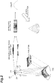
- FIG. 2 is a view describing a height measurement and shape estimation process of the sample 100.
- the sample 100 is obliquely irradiated with light including a plurality of wavelengths, reflected light from the sample 100 passes through a lens 21 (to be described later) and is separated by an inclined dichroic mirror 22 (to be described later), the separated light is detected by light detectors 23 and 24 (to be described later) that are line sensors or the like, wavelength information of light at each irradiation point is restored based on a distribution of the brightness (light quantity) of the light detected by each of the light detectors 23 and 24, a height at each irradiation point is calculated based on the wavelength information, and the shape of the sample 100 is restored based on the height of each irradiation point. Details will be described later.
- the height measurement apparatus 1 includes a light irradiation unit 10, a camera system 20 (light detection unit), a control apparatus 30 (analysis unit), a dark box 40, and a belt conveyor 50 (conveyor unit).
- the belt conveyor 50 is a conveyor unit that moves the sample 100.
- the belt conveyor 50 moves the sample 100 in one direction of a horizontal direction to change the irradiation point of irradiation light (irradiation light emitted from the light irradiation unit 10) on the sample 100.
- the belt conveyor 50 includes a belt unit 52 on which the sample 100 is placed and which moves in the one direction, and an actuator 51 that operates the belt unit 52.
- the actuator 51 is controlled by a control unit 31 (to be described later) of the control apparatus 30.
- the dark box 40 accommodates at least the light irradiation unit 10, the camera system 20, and a part of the belt conveyor 50 (in detail, a point at which the sample 100 placed on the belt conveyor 50 is irradiated with the irradiation light from the light irradiation unit 10) among the above-described configurations of the height measurement apparatus 1, and is provided to avoid the influence of external light on the accommodated configurations.
- the dark box 40 blocks light other than the light emitted from the light irradiation unit 10 as light with which the sample 100 is to be irradiated.
- the light irradiation unit 10 irradiates the sample 100 with irradiation light including a plurality of light fluxes arranged in a direction intersecting an optical axis direction and having different wavelengths, at an angle inclined with respect to a height direction of the sample 100 (measurement object).
- irradiation light including a plurality of light fluxes arranged in a direction intersecting an optical axis direction and having different wavelengths, at an angle inclined with respect to a height direction of the sample 100 (measurement object).
- flat light fluxes Li1, Li2, ... LiX (X is an integer) having different wavelengths are arranged along the direction intersecting the optical axis direction without a gap therebetween.
- the angle inclined with respect to the height direction of the sample 100 is an angle other than a vertical direction and in more detail, is an angle (angle in an oblique direction) other than the vertical direction and the horizontal direction.
- a light flux only one of the flat light fluxes Li1, Li2, ... LiX
- the light irradiation unit 10 irradiates the sample 100 with the irradiation light including the plurality of light fluxes that are parallel light.
- the light irradiation unit 10 includes, for example, a light source 11 and spectral elements 12 and 13. As described above, the light irradiation unit 10 includes two spectral elements 12 and 13 as elements related to light spectroscopy.
- the light source 11 is, for example, a white light source that outputs white light and is, for example, a white LED, a lamp light source, a supercontinuum light source, a laser-excited white light source, or the like.
- the light source 11 may be a light source that outputs light other than white light.
- the light emitted from the light source 11 is light including a wavelengths to be reflected and scattered by the sample 100, and is selected according to the sample 100.
- the light source 11 outputs light of a wavelength included in a predetermined wavelength range of the inclined dichroic mirror 22 (to be described later) (wavelength range in which the transmittance and the reflectance of the inclined dichroic mirror 22 change according to the wavelength) provided in the camera system 20.
- the horizontal axis represents the wavelength
- the vertical axis represents the transmittance of the inclined dichroic mirror 22.
- a characteristic X4 of the inclined dichroic mirror 22 in FIG. 5 the transmittance (and the reflectance) of light gradually changes according to a change in wavelength in a predetermined wavelength range XI, and regardless of a change in wavelength, the transmittance (and the reflectance) of light is constant in a wavelength range other than the specific wavelength range.
- the transmittance of light changes in a monotonically increasing manner (the reflectance changes in a monotonically decreasing manner) in a specific wavelength band (wavelength band of wavelength ⁇ 1 to ⁇ 2 ) according to a change in wavelength.
- light X2 output from the light source 11 includes light of a wavelength included in the predetermined wavelength range X1 described above. Namely, the light source 11 outputs light of a broad spectrum including the predetermined wavelength range X1.
- the spectral elements 12 and 13 split the white light output from the light source 11 for each wavelength (split the white light into rainbow colors of light), to output irradiation light including a plurality of the flat light fluxes Li1, Li2, ... LiX having different wavelengths, in the direction intersecting the optical axis direction.
- the spectral element 12 receives the white light output from the light source 11 and outputs light toward the spectral element 13.
- the spectral element 13 receives the light output from the spectral element 12 and outputs the irradiation light that is parallel light, toward the sample 100.
- FIG. 3 is a view illustrating a configuration example of the light irradiation unit 10.
- the light irradiation unit 10 illustrated in FIG. 3(a) includes diffraction gratings 12a and 13a as the spectral elements 12 and 13.
- the diffraction gratings 12a and 13a output a light flux of each wavelength such that the longer the wavelength is, the more easily the light flux is bent.
- the diffraction grating 13a may be a lens.
- the light irradiation unit 10 illustrated in FIG. 3(b) includes prisms 12b and 13b as the spectral elements 12 and 13.
- the prisms 12b and 13b output a light flux of each wavelength such that the shorter the wavelength is, the more easily the light flux is bent, depending on the refractive index for each wavelength.
- the prism 13b may be a lens.
- the spectral elements 12 and 13 are the diffraction gratings 12a and 13a.
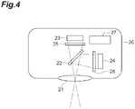
- FIG. 4 is a view schematically illustrating the camera system 20 illustrated in FIG. 1 .
- the camera system 20 includes the lens 21, the inclined dichroic mirror 22 (optical element), the light detectors 23 and 24 (a first light detector and a second light detector), bandpass filters 25 and 26, and a processing unit 27.
- the lens 21 is a lens that concentrates the incident light from the sample 100.
- the lens 21 may be disposed in a front stage (upstream) of the inclined dichroic mirror 22 or may be disposed in a region between the inclined dichroic mirror 22 and each of the light detectors 23 and 24.
- the lens 21 may be a finite focus lens or an infinite focus lens. When the lens 21 is a finite focus lens, the distance from the lens 21 to each of the light detectors 23 and 24 has a predetermined value. When the lens 21 is an infinite focus lens, the lens 21 is a collimator lens that converts the light from the sample 100 into parallel light, and is aberration-corrected to obtain the parallel light.
- the light output from the lens 21 is incident on the inclined dichroic mirror 22.
- the inclined dichroic mirror 22 is a mirror made of a special optical material, and is an optical element that separates the light from the sample 100 by transmitting and reflecting the light according to the wavelength.
- the inclined dichroic mirror 22 is configured such that the transmittance and the reflectance of light change according to the wavelength in a predetermined wavelength range.
- FIG. 5 is a graph describing a spectrum of light and the characteristic of the inclined dichroic mirror 22.
- the horizontal axis represents the wavelength
- the vertical axis represents the spectral intensity (in the case of the spectrum of light) and the transmittance (in the case of the inclined dichroic mirror 22).
- the transmittance (and the reflectance) of light gradually changes according to a change in wavelength in a predetermined wavelength range (wavelength range of wavelength ⁇ 1 to ⁇ 2 ), and regardless of a change in wavelength, the transmittance (and the reflectance) of light is constant in a wavelength range (namely, on a wavelength side lower than the wavelength ⁇ 1 and on a wavelength side higher than the wavelength ⁇ 2 ) other than the predetermined wavelength range.
- the transmittance and the reflectance have a negative correlation in which one changes in an increasing direction and the other changes in a decreasing direction, hereinafter, the transmittance and the reflectance may be simply written as the "transmittance” instead of being written as the "transmittance (and the reflectance)".
- the transmittance of light is constant regardless of a change in wavelength” includes not only a case where the transmittance of light is completely constant, but also, for example, a case where a change in transmittance for a change of 1 nm in wavelength is 0.1% or less.
- the transmittance of light On the wavelength side lower than the wavelength ⁇ 1 , the transmittance of light is approximately 0% regardless of a change in wavelength, and on the wavelength side higher than the wavelength ⁇ 2 , the transmittance of light is approximately 100% regardless of a change in wavelength.
- the transmittance of light is approximately 0% includes a transmittance of approximately 0% + 10%
- the transmittance of light is approximately 100% includes a transmittance of approximately 100% - 10%.
- the light detectors 23 and 24 detect the light separated by the inclined dichroic mirror 22.
- the light detectors 23 and 24 are, for example, one-dimensional line sensors.
- the light detector 23 detects a transmitted light quantity from light transmitted through the inclined dichroic mirror 22.
- the light detector 24 detects light reflected by the inclined dichroic mirror 22.
- the range of a wavelength to which the light detectors 23 and 24 have sensitivity corresponds to the predetermined wavelength range in which the transmittance (and the reflectance) of light in the inclined dichroic mirror 22 changes according to a change in wavelength.
- the bandpass filter 25 is disposed between the inclined dichroic mirror 22 and the light detector 23.
- the bandpass filter 26 is disposed between the inclined dichroic mirror 22 and the light detector 24.
- the bandpass filters 25 and 26 may be, for example, filters that remove light in a wavelength range other than the predetermined wavelength range described above (wavelength range in which the transmittance and the reflectance of light in the inclined dichroic mirror 22 change according to the wavelength).
- the processing unit 27 calculates the wavelength information based on a ratio between the transmitted light quantity detected by the light detector 23 and a reflected light quantity detected by the light detector 24, to output the wavelength information to the control apparatus 30.
- light with which one point on the sample 100 moved by the belt conveyor 50 is irradiated is monochromatic. Namely, light with which one point on the sample 100 is irradiated is only light of a light flux in the irradiation light including a plurality of light fluxes having different wavelengths, and is monochromatic.
- a wavelength shift parameter S T ⁇ R / T + R
- the processing unit 27 outputs the wavelength (wavelength information) derived using these equations, to the control apparatus 30.
- control apparatus 30 is a computer and physically includes memories such as a RAM and a ROM, a processor (arithmetic circuit) such as a CPU, a communication interface, and a storage unit such as a hard disk.
- the function of the control apparatus 30 is realized by causing the CPU of a computer system to execute a program stored in the memory.
- the control apparatus 30 may be configured as a microcomputer or an FPGA.
- the control apparatus 30 includes the control unit 31, a calculation unit 32, and a display unit 33.
- the control unit 31 controls each configuration of the height measurement apparatus 1. Specifically, the control unit 31 controls the camera system 20 and controls the actuator 51 of the belt conveyor 50.
- the control unit 31 controls a line rate of the light detectors 23 and 24 that are, for example, line sensors, inside the camera system 20 by adjusting a conveyance speed of the belt conveyor 50 through controlling the actuator.
- the calculation unit 32 calculates a height of the sample 100 (height of one point on the sample 100 with which the irradiation light is irradiated) based on the wavelength information derived by the processing unit 27.
- the calculation unit 32 calculates a height of the sample 100 based on a pitch D of the diffraction grating, the wavelength ⁇ , and a distance L between the spectral elements 12 and 13.
- a height h for each wavelength is expressed by the following Equation (4)
- a height H of the sample 100 is expressed by the following Equation (5).
- ⁇ is an inclination angle of light with respect to the spectral element 13
- ⁇ is an inclination angle of the irradiation light from the horizontal direction.
- the calculation unit 32 may derive the shape of sample 100 by calculating a height corresponding to each irradiation point on the sample 100.
- a height corresponding to each irradiation point on the sample 100 For example, when the light detectors 23 and 24 are line sensors, since a height is measured for one line, a three-dimensional shape of the sample 100 can be derived by continuously calculating a height of each line.
- prisms are used as the spectral elements 12 and 13
- a height cannot be simply calculated, so that a height is calculated not by the above-described equations, but by conversion using a table obtained in advance or by an approximate value from an approximate curve.
- the display unit 33 displays information related to the height of the sample 100 calculated by the calculation unit 32.
- the display unit 33 displays, for example, detection results (imaging results) of the light detectors 23 and 24 and information indicating the height of the sample 100.
- the display unit 33 may display the shape (restored shape) of the sample 100 derived from the height corresponding each irradiation point.
- FIG. 6 is a flowchart illustrating the height measurement method according to the present embodiment.
- the sample 100 is obliquely irradiated with irradiation light while the sample 100 is moved by the belt conveyor 50 (step S1: light irradiation step).
- the irradiation light includes a plurality of light fluxes arranged in a direction intersecting an optical axis direction and having different wavelengths.
- wavelength information of light is calculated based on reflected light from the sample 100 (step S2: wavelength calculation step). Specifically, wavelength information is calculated based on a ratio between a transmitted light quantity and a reflected light quantity separated by the inclined dichroic mirror 22.
- a height of the sample 100 is calculated based on the wavelength information (step S3: height calculation step).
- a shape of the sample 100 may be restored (derived) by calculating a height corresponding to each irradiation point on the sample 100 on which the irradiation point changes when the sample 100 moves. The above is the height measurement method performed by the height measurement apparatus 1.
- the height measurement apparatus 1 includes: the light irradiation unit 10 that irradiates the sample 100 with irradiation light including a plurality of light fluxes arranged in a direction intersecting an optical axis direction and having different wavelengths, at an angle inclined with respect to a height direction of the sample 100; the camera system 20 that detects light from the sample 100 irradiated with the irradiation light, to output wavelength information of the light; and the control apparatus 30 that calculates a height of the sample 100 based on the wavelength information.
- the camera system 20 includes the inclined dichroic mirror 22 of which a transmittance and a reflectance change according to a wavelength in a predetermined wavelength range and which separates the light from the sample 100 by transmitting and reflecting the light, the light detector 24 that detects a reflected light quantity from light reflected by the inclined dichroic mirror 22, the light detector 23 that detects a transmitted light quantity from light transmitted through the inclined dichroic mirror 22, and the processing unit 27 that calculates the wavelength information based on a ratio between the reflected light quantity and the transmitted light quantity, to output the wavelength information.
- the sample 100 is irradiated with the irradiation light including the plurality of light fluxes arranged in the direction intersecting the optical axis direction and having different wavelengths, at an angle inclined with respect to the height direction of the sample 100, wavelength information is derived based on the light from the sample 100 and is output, and a height of the sample 100 is calculated based on the wavelength information.
- the wavelength of the light with which the sample 100 is irradiated changes depending on the height of the sample 100.
- the height of the sample 100 can be appropriately calculated based on the wavelength information.
- the light is separated by the inclined dichroic mirror 22 of which the transmittance and the reflectance change according to the wavelength, the reflected light quantity is detected from the light reflected by the inclined dichroic mirror 22, the transmitted light quantity is detected from the light transmitted through the inclined dichroic mirror 22, and the wavelength information is calculated based on the ratio between the reflected light quantity and the transmitted light quantity.
- the wavelength information of the light can be calculated with high accuracy without being affected by a color of the sample 100 itself.
- the height of the sample 100 can be calculated with high accuracy based on the wavelength information of the light calculated with high accuracy.
- the calculation accuracy can be improved, for example, by correcting distortion of characteristics of a filter or the transmittance or the like of a lens, and for example, when the "predetermined wavelength range" of the inclined dichroic mirror 22 (wavelength range in which the transmittance and the reflectance change according to the wavelength) is designed to be 400 nm to 700 nm, the error can be approximately 1 nm.
- the light detectors 23 and 24 may be line sensors. Since the line sensors are used, for example, imaging is performed on each imaging line with high accuracy while changing the imaging line by moving the sample 100. Accordingly, the height of the sample 100 can be calculated with higher accuracy.
- the light irradiation unit 10 may irradiate the sample 100 with the irradiation light including the plurality of light fluxes that are parallel light. Since the sample 100 is irradiated with parallel light, a correspondence between the wavelength and the height can be easily and appropriately derived, and the height of the sample 100 can be calculated with higher accuracy.
- the light irradiation unit 10 may include a light source 11 that emits white light, and spectral elements 12 and 13 that split the white light output from the light source 11, to output the irradiation light including the plurality of light fluxes having different wavelengths, in the direction intersecting the optical axis direction.
- the irradiation light including the plurality of light fluxes having different wavelengths can be easily and appropriately output by splitting the white light including all visible rays and by outputting each light flux.
- the height measurement apparatus 1 further includes a dark box 40 that blocks light other than the light with which the sample 100 is irradiated by the light irradiation unit 10, as light with which the sample 100 is to be irradiated. According to such a configuration, the height of the sample 100 can be calculated with higher accuracy by blocking the light that is not related to the height measurement.
- the height measurement apparatus 1 may further include a belt conveyor 50 that moves the sample 100. According to such a configuration, the height of the entire sample 100 can be measured by deriving wavelength information of the entire sample 100 while changing an irradiation point of the irradiation light on the sample 100.
- the height measurement method includes: a light irradiation step of irradiating the sample 100 with irradiation light including a plurality of light fluxes arranged in a direction intersecting an optical axis direction and having different wavelengths, at an angle inclined with respect to a height direction of the sample 100; a wavelength calculation step of calculating wavelength information of light from the sample 100 based on a ratio between a reflected light quantity and a transmitted light quantity obtained by the light detector 24 that detects the reflected light quantity from light reflected by the inclined dichroic mirror 22 of which a transmittance and a reflectance change according to a wavelength in a predetermined wavelength range and which separates the light from the sample 100 by transmitting and reflecting the light, and by the light detector 23 that detects the transmitted light quantity from light transmitted through the inclined dichroic mirror 22; and a height calculation step of calculating a height of the sample 100 based on the wavelength information. According to such a height measurement method, the height of the sample 100 can be calculated with high accuracy
- an irradiation point of the irradiation light on the sample 100 may be continuously changed by moving the sample 100, and in the height calculation step, a shape of the sample 100 may be derived by calculating a height corresponding to the each irradiation point on the sample 100.
- the irradiation point of the irradiation light on the sample 100 is continuously changed to measure the height of the entire sample 100, and the shape of the sample 100 can be appropriately derived based on a result of the height measurement.
- a shape of a measurement object is measured by irradiating the measurement object with linear light and observing the measurement object in an oblique direction with a camera.
- this method since this method must require a two-dimensional sensor, the measurement speed is slow and the processing load is high compared to a case where a one-dimensional sensor such as a line sensor is used.
- the method using a TOF sensor pulsed light is applied to a measurement object, and the unevenness of the measurement object is measured from the timing at which the pulsed light is output and from the time taken for the pulsed light to bounce back from the measurement object.
- this method it is difficult to enlarge pixels due to the characteristic of measuring a very short time, and this method is not suitable for observing a fine shape.
- the shape measurement method performed by the height measurement apparatus 1 according to the present embodiment the measurement speed can be increased, the processing load can be reduced, and a fine shape can also be appropriately measured compared to the comparative examples.
- 1 height measurement apparatus
- 10 light irradiation unit
- 11 light source
- 12, 13 spectral element
- 20 camera system (light detection unit)
- 22 inclined dichroic mirror (optical element)
- 23, 24 light detector (first light detector, second light detector)
- 25, 26 bandpass filter
- 27 processing unit
- 30 control apparatus (analysis unit)
- 40 dark box
- 50 belt conveyor (conveyor unit)
- 100 sample (measurement object).
Landscapes
- Physics & Mathematics (AREA)
- General Physics & Mathematics (AREA)
- Spectroscopy & Molecular Physics (AREA)
- Engineering & Computer Science (AREA)
- Computer Networks & Wireless Communication (AREA)
- Radar, Positioning & Navigation (AREA)
- Remote Sensing (AREA)
- Optics & Photonics (AREA)
- Electromagnetism (AREA)
- Chemical & Material Sciences (AREA)
- Immunology (AREA)
- Life Sciences & Earth Sciences (AREA)
- Pathology (AREA)
- Analytical Chemistry (AREA)
- Biochemistry (AREA)
- General Health & Medical Sciences (AREA)
- Health & Medical Sciences (AREA)
- Mathematical Physics (AREA)
- Length Measuring Devices By Optical Means (AREA)
- Investigating Or Analysing Materials By Optical Means (AREA)
- Spectrometry And Color Measurement (AREA)
- Optical Filters (AREA)
- Blocking Light For Cameras (AREA)
- Studio Devices (AREA)
- Testing Or Measuring Of Semiconductors Or The Like (AREA)
Abstract
Description
- One aspect of the present invention relates to a height measurement apparatus and a height measurement method.
- As a method for measuring a height of a measurement object, a method for measuring a height by irradiating the measurement object with light and by detecting light from the measurement object has been known (for example, refer to
Patent Literatures 1 to 3). In the height measurement method disclosed inPatent Literatures 1 to 3, a measurement object is irradiated with irradiation light including a plurality of light fluxes arranged in a direction intersecting an optical axis direction and having different wavelengths, at an angle inclined with respect to a height direction of the measurement object, and a height of the measurement object is measured based on a wavelength of reflected light from the measurement object. -
- Patent Literature 1:
Japanese Unexamined Patent Publication No. H7-27520 - Patent Literature 2:
Japanese Unexamined Patent Publication No. 2007-101399 - Patent Literature 3:
Japanese Unexamined Patent Publication No. 2009-145279 - Here, in the above-described height measurement method, the wavelength of the light from the measurement object is obtained by a color imaging element. When the wavelength of the light is obtained in such a manner, since the derivation of the wavelength of the light is affected by a color of the measurement object itself, the accuracy of a final height measurement result of the measurement object decreases, which is a concern.
- One aspect of the present invention is conceived in view of the above circumstances, and an object of the present invention is to provide a height measurement apparatus and a height measurement method capable of measuring a height of a measurement object with higher accuracy.
- A height measurement apparatus according to one aspect of the present invention includes: a light irradiation unit that irradiates a measurement object with irradiation light including a plurality of light fluxes arranged in a direction intersecting an optical axis direction and having different wavelengths, at an angle inclined with respect to a height direction of the measurement object; a light detection unit that detects light from the measurement object irradiated with the irradiation light, to output wavelength information of the light; and an analysis unit that calculates a height of the measurement object based on the wavelength information. The light detection unit includes an optical element of which a transmittance and a reflectance change according to a wavelength in a predetermined wavelength range and which separates the light from the measurement object by transmitting and reflecting the light, a first light detector that detects a reflected light quantity from light reflected by the optical element, a second light detector that detects a transmitted light quantity from light transmitted through the optical element, and a processing unit that calculates the wavelength information based on a ratio between the reflected light quantity and the transmitted light quantity, to output the wavelength information.
- In the height measurement apparatus according to one aspect of the present invention, the measurement object is irradiated with the irradiation light including the plurality of light fluxes arranged in the direction intersecting the optical axis direction and having different wavelengths, at an angle inclined with respect to the height direction of the measurement object, wavelength information is derived based on light from the measurement object and is output, and a height of the measurement object is calculated based on the wavelength information. As described above, since the measurement object is obliquely (at an inclined angle) irradiated with the irradiation light including the plurality of different light fluxes, in the direction intersecting the optical axis direction, the wavelength of the light with which the measurement object is irradiated changes depending on the height of the measurement object. Therefore, when the light from the measurement object is detected and the wavelength information is derived, the height of the measurement object can be appropriately calculated based on the wavelength information. Here, in the height measurement apparatus according to one aspect of the present invention, the light is separated by the optical element of which the transmittance and the reflectance change according to the wavelength, the reflected light quantity is detected from the light reflected by the optical element, the transmitted light quantity is detected from the light transmitted through the optical element, and the wavelength information is calculated based on the ratio between the reflected light quantity and the transmitted light quantity. For example, when a wavelength of light from a measurement object is derived based on the intensity of light acquired by a color imaging element, since the intensity of light acquired by the color imaging element changes due to being affected by a color of the measurement object itself, the calculation accuracy of wavelength information of the light cannot be guaranteed, which is a concern. In this case, the height measurement accuracy of the measurement object based on the wavelength information also decreases. In this regard, in the height measurement apparatus according to one aspect of the present invention, as described above, since the light is separated by the optical element of which the transmittance and the reflectance change according to the wavelength, and the wavelength information is calculated based on the ratio between the reflected light quantity and the transmitted light quantity that are separated, the wavelength information of the light can be calculated with high accuracy without being affected by a color of the measurement object itself. According to the height measurement apparatus, the height of the measurement object can be calculated with high accuracy based on the wavelength information of the light calculated with high accuracy.
- In the height measurement apparatus, the first light detector and the second light detector may be line sensors. Since the line sensors are used, for example, imaging is performed on each imaging line with high accuracy while changing the imaging line by moving the measurement object. Accordingly, the height of the measurement object can be calculated with higher accuracy.
- In the height measurement apparatus, the light irradiation unit may irradiate the measurement object with the irradiation light including the plurality of light fluxes that are parallel light. Since the measurement object is irradiated with parallel light, a correspondence between the wavelength and the height can be easily and appropriately derived, and the height of the measurement object can be calculated with higher accuracy.
- In the height measurement apparatus, the light irradiation unit may include a light source that emits white light, and a spectral element that splits the white light output from the light source, to output the irradiation light including the plurality of light fluxes having different wavelengths, in the direction intersecting the optical axis direction. As described above, the irradiation light including the plurality of light fluxes having different wavelengths can be easily and appropriately output by splitting the white light including all visible rays and by outputting each light flux.
- The height measurement apparatus may further include a dark box that blocks light other than the light with which the measurement object is irradiated by the light irradiation unit, as light with which the measurement object is to be irradiated. According to such a configuration, the height of the measurement object can be calculated with higher accuracy by blocking the light that is not related to the height measurement.
- The height measurement apparatus may further include a conveyor unit that moves the measurement object. According to such a configuration, the height of the entire measurement object can be measured by deriving wavelength information of the entire measurement object while changing an irradiation point of the irradiation light on the measurement object.
- A height measurement method according to one aspect of the present invention includes: a light irradiation step of irradiating a measurement object with irradiation light including a plurality of light fluxes arranged in a direction intersecting an optical axis direction and having different wavelengths, at an angle inclined with respect to a height direction of the measurement object; a wavelength calculation step of calculating wavelength information of light from the measurement object based on a ratio between a reflected light quantity and a transmitted light quantity obtained by an optical element of which a transmittance and a reflectance change according to a wavelength in a predetermined wavelength range and which separates the light from the measurement object by transmitting and reflecting the light, by a first light detector that detects the reflected light quantity from light reflected by the optical element, and by a second light detector that detects the transmitted light quantity from light transmitted through the optical element; and a height calculation step of calculating a height of the measurement object based on the wavelength information. According to such a height measurement method, the height of the measurement object can be calculated with high accuracy based on the wavelength information of the light calculated with high accuracy.
- In the height measurement method, in the light irradiation step, an irradiation point of the irradiation light on the measurement object may be continuously changed by moving the measurement object, and in the height calculation step, a shape of the measurement object may be derived by calculating a height corresponding to the each irradiation point on the measurement object. In such a height measurement method, the irradiation point of the irradiation light on the measurement object is continuously changed to measure the height of the entire measurement object, and the shape of the measurement object can be appropriately derived based on a result of the height measurement.
- In the height measurement apparatus according to one aspect of the present invention, the height of the measurement object can be measured with higher accuracy.
-
-
FIG. 1 is a view schematically illustrating a height measurement apparatus according to the present embodiment. -
FIG. 2 is a view describing a height measurement and shape estimation process of a measurement object. -
FIG. 3 is a view illustrating a configuration example of a light irradiation unit illustrated inFIG. 1 . -
FIG. 4 is a view schematically illustrating a camera system illustrated inFIG. 1 . -
FIG. 5 is a graph describing a spectrum of light and a characteristic of an inclined dichroic mirror. -
FIG. 6 is a flowchart illustrating a height measurement method according to the present embodiment. - Hereinafter, an embodiment of the present invention will be described in detail with reference to the drawings. Incidentally, in the drawings, the same or corresponding portions are denoted by the same reference signs, and a duplicated description will be omitted.
-
FIG. 1 is a view schematically illustrating aheight measurement apparatus 1 according to the present embodiment. Theheight measurement apparatus 1 is an apparatus that irradiates asample 100 with light to measure a height of thesample 100 based on reflected light from thesample 100. Theheight measurement apparatus 1 may calculate a height of each region of thesample 100 by continuously changing an irradiation point of the light on thesample 100, and finally derive a shape of thesample 100 based on the height of each region. Thesample 100 may be any object of which a height is desired to be measured and is, for example, food, various processed products, or the like. -
FIG. 2 is a view describing a height measurement and shape estimation process of thesample 100. In a height measurement method and a shape estimation method performed by theheight measurement apparatus 1 according to the present embodiment, as illustrated inFIG. 2 , thesample 100 is obliquely irradiated with light including a plurality of wavelengths, reflected light from thesample 100 passes through a lens 21 (to be described later) and is separated by an inclined dichroic mirror 22 (to be described later), the separated light is detected bylight detectors 23 and 24 (to be described later) that are line sensors or the like, wavelength information of light at each irradiation point is restored based on a distribution of the brightness (light quantity) of the light detected by each of thelight detectors sample 100 is restored based on the height of each irradiation point. Details will be described later. - As illustrated in
FIG. 1 , theheight measurement apparatus 1 includes alight irradiation unit 10, a camera system 20 (light detection unit), a control apparatus 30 (analysis unit), adark box 40, and a belt conveyor 50 (conveyor unit). - The belt conveyor 50 is a conveyor unit that moves the
sample 100. The belt conveyor 50 moves thesample 100 in one direction of a horizontal direction to change the irradiation point of irradiation light (irradiation light emitted from the light irradiation unit 10) on thesample 100. The belt conveyor 50 includes abelt unit 52 on which thesample 100 is placed and which moves in the one direction, and anactuator 51 that operates thebelt unit 52. Theactuator 51 is controlled by a control unit 31 (to be described later) of thecontrol apparatus 30. - The
dark box 40 accommodates at least thelight irradiation unit 10, thecamera system 20, and a part of the belt conveyor 50 (in detail, a point at which thesample 100 placed on the belt conveyor 50 is irradiated with the irradiation light from the light irradiation unit 10) among the above-described configurations of theheight measurement apparatus 1, and is provided to avoid the influence of external light on the accommodated configurations. Thedark box 40 blocks light other than the light emitted from thelight irradiation unit 10 as light with which thesample 100 is to be irradiated. - The
light irradiation unit 10 irradiates thesample 100 with irradiation light including a plurality of light fluxes arranged in a direction intersecting an optical axis direction and having different wavelengths, at an angle inclined with respect to a height direction of the sample 100 (measurement object). In the irradiation light emitted from thelight irradiation unit 10 to thesample 100, as illustrated inFIG. 1 , flat light fluxes Li1, Li2, ... LiX (X is an integer) having different wavelengths are arranged along the direction intersecting the optical axis direction without a gap therebetween. The angle inclined with respect to the height direction of thesample 100 is an angle other than a vertical direction and in more detail, is an angle (angle in an oblique direction) other than the vertical direction and the horizontal direction. When thesample 100 is irradiated with such irradiation light, one point on thesample 100 is irradiated with a light flux (only one of the flat light fluxes Li1, Li2, ... LiX) of a color differing depending on the height. For this reason, a height at an irradiation point of thesample 100 can be derived by observing light reflected from thesample 100. Thelight irradiation unit 10 irradiates thesample 100 with the irradiation light including the plurality of light fluxes that are parallel light. Thelight irradiation unit 10 includes, for example, alight source 11 andspectral elements light irradiation unit 10 includes twospectral elements - The
light source 11 is, for example, a white light source that outputs white light and is, for example, a white LED, a lamp light source, a supercontinuum light source, a laser-excited white light source, or the like. Thelight source 11 may be a light source that outputs light other than white light. The light emitted from thelight source 11 is light including a wavelengths to be reflected and scattered by thesample 100, and is selected according to thesample 100. Thelight source 11 outputs light of a wavelength included in a predetermined wavelength range of the inclined dichroic mirror 22 (to be described later) (wavelength range in which the transmittance and the reflectance of the inclineddichroic mirror 22 change according to the wavelength) provided in thecamera system 20.FIG. 5 is a graph describing a relationship between a characteristic of the inclineddichroic mirror 22 and a wavelength of the light emitted from thelight source 11. InFIG. 5 , the horizontal axis represents the wavelength, and the vertical axis represents the transmittance of the inclineddichroic mirror 22. As illustrated by a characteristic X4 of the inclineddichroic mirror 22 inFIG. 5 , in the inclineddichroic mirror 22, the transmittance (and the reflectance) of light gradually changes according to a change in wavelength in a predetermined wavelength range XI, and regardless of a change in wavelength, the transmittance (and the reflectance) of light is constant in a wavelength range other than the specific wavelength range. In other words, the transmittance of light changes in a monotonically increasing manner (the reflectance changes in a monotonically decreasing manner) in a specific wavelength band (wavelength band of wavelength λ1 to λ2) according to a change in wavelength. As illustrated inFIG. 5 , light X2 output from thelight source 11 includes light of a wavelength included in the predetermined wavelength range X1 described above. Namely, thelight source 11 outputs light of a broad spectrum including the predetermined wavelength range X1. - Returning to
FIG. 1 , thespectral elements light source 11 for each wavelength (split the white light into rainbow colors of light), to output irradiation light including a plurality of the flat light fluxes Li1, Li2, ... LiX having different wavelengths, in the direction intersecting the optical axis direction. Thespectral element 12 receives the white light output from thelight source 11 and outputs light toward thespectral element 13. Thespectral element 13 receives the light output from thespectral element 12 and outputs the irradiation light that is parallel light, toward thesample 100. -
FIG. 3 is a view illustrating a configuration example of thelight irradiation unit 10. Thelight irradiation unit 10 illustrated in FIG. 3(a) includesdiffraction gratings spectral elements diffraction gratings diffraction grating 13a may be a lens. Thelight irradiation unit 10 illustrated in FIG. 3(b) includesprisms spectral elements prisms prism 13b may be a lens. Hereinafter, a description will be given based on a case where thespectral elements diffraction gratings - Returning to
FIG. 1 , thecamera system 20 detects light from thesample 100 irradiated with the irradiation light from thelight irradiation unit 10, to output wavelength information of the light. Thecamera system 20 is disposed at a position where the light from thesample 100 can be detected.FIG. 4 is a view schematically illustrating thecamera system 20 illustrated inFIG. 1 . As illustrated inFIG. 4 , thecamera system 20 includes thelens 21, the inclined dichroic mirror 22 (optical element), thelight detectors 23 and 24 (a first light detector and a second light detector), bandpass filters 25 and 26, and aprocessing unit 27. - The
lens 21 is a lens that concentrates the incident light from thesample 100. Thelens 21 may be disposed in a front stage (upstream) of the inclineddichroic mirror 22 or may be disposed in a region between the inclineddichroic mirror 22 and each of thelight detectors lens 21 may be a finite focus lens or an infinite focus lens. When thelens 21 is a finite focus lens, the distance from thelens 21 to each of thelight detectors lens 21 is an infinite focus lens, thelens 21 is a collimator lens that converts the light from thesample 100 into parallel light, and is aberration-corrected to obtain the parallel light. The light output from thelens 21 is incident on the inclineddichroic mirror 22. - The inclined
dichroic mirror 22 is a mirror made of a special optical material, and is an optical element that separates the light from thesample 100 by transmitting and reflecting the light according to the wavelength. The inclineddichroic mirror 22 is configured such that the transmittance and the reflectance of light change according to the wavelength in a predetermined wavelength range. -
FIG. 5 is a graph describing a spectrum of light and the characteristic of the inclineddichroic mirror 22. InFIG. 5 , the horizontal axis represents the wavelength, and the vertical axis represents the spectral intensity (in the case of the spectrum of light) and the transmittance (in the case of the inclined dichroic mirror 22). As illustrated by the characteristic X4 of the inclineddichroic mirror 22 inFIG. 5 , in the inclineddichroic mirror 22, the transmittance (and the reflectance) of light gradually changes according to a change in wavelength in a predetermined wavelength range (wavelength range of wavelength λ1 to λ2), and regardless of a change in wavelength, the transmittance (and the reflectance) of light is constant in a wavelength range (namely, on a wavelength side lower than the wavelength λ1 and on a wavelength side higher than the wavelength λ2) other than the predetermined wavelength range. Since the transmittance and the reflectance have a negative correlation in which one changes in an increasing direction and the other changes in a decreasing direction, hereinafter, the transmittance and the reflectance may be simply written as the "transmittance" instead of being written as the "transmittance (and the reflectance)". Incidentally, "the transmittance of light is constant regardless of a change in wavelength" includes not only a case where the transmittance of light is completely constant, but also, for example, a case where a change in transmittance for a change of 1 nm in wavelength is 0.1% or less. On the wavelength side lower than the wavelength λ1, the transmittance of light is approximately 0% regardless of a change in wavelength, and on the wavelength side higher than the wavelength λ2, the transmittance of light is approximately 100% regardless of a change in wavelength. Incidentally, "the transmittance of light is approximately 0%" includes a transmittance of approximately 0% + 10%, and "the transmittance of light is approximately 100%" includes a transmittance of approximately 100% - 10%. - Returning to
FIG. 4 , thelight detectors dichroic mirror 22. Thelight detectors light detector 23 detects a transmitted light quantity from light transmitted through the inclineddichroic mirror 22. Thelight detector 24 detects light reflected by the inclineddichroic mirror 22. The range of a wavelength to which thelight detectors dichroic mirror 22 changes according to a change in wavelength. - The
bandpass filter 25 is disposed between the inclineddichroic mirror 22 and thelight detector 23. Thebandpass filter 26 is disposed between the inclineddichroic mirror 22 and thelight detector 24. The bandpass filters 25 and 26 may be, for example, filters that remove light in a wavelength range other than the predetermined wavelength range described above (wavelength range in which the transmittance and the reflectance of light in the inclineddichroic mirror 22 change according to the wavelength). - The
processing unit 27 calculates the wavelength information based on a ratio between the transmitted light quantity detected by thelight detector 23 and a reflected light quantity detected by thelight detector 24, to output the wavelength information to thecontrol apparatus 30. In theheight measurement apparatus 1, light with which one point on thesample 100 moved by the belt conveyor 50 is irradiated is monochromatic. Namely, light with which one point on thesample 100 is irradiated is only light of a light flux in the irradiation light including a plurality of light fluxes having different wavelengths, and is monochromatic. When a wavelength (wavelength that is desired to be derived) of the irradiation light is λ, the transmitted light quantity is T, and the reflected light quantity is R, a wavelength shift parameter S is expressed by the following Equation (1).
- Here, when a wavelength at which the reflectance is 100% is λ1 and a wavelength at which the transmittance is 100% is λ2 in the inclined
dichroic mirror 22, it is clear that a wavelength λ50% for a transmittance of 50% is (λ1 + λ2)/2, from the characteristic of the inclined dichroic mirror which causes the rate of change to linearly change with respect to the wavelength. At this time, the wavelength shift parameter S is 0. From here, the amount of change when the wavelength is shifted by Δλ is expressed by the following Equation (2) using the wavelength shift parameter S. In addition, the wavelength λ is expressed by the following Equation (3).

- The
processing unit 27 outputs the wavelength (wavelength information) derived using these equations, to thecontrol apparatus 30. - Returning to
FIG. 1 , thecontrol apparatus 30 is a computer and physically includes memories such as a RAM and a ROM, a processor (arithmetic circuit) such as a CPU, a communication interface, and a storage unit such as a hard disk. The function of thecontrol apparatus 30 is realized by causing the CPU of a computer system to execute a program stored in the memory. Thecontrol apparatus 30 may be configured as a microcomputer or an FPGA. - The
control apparatus 30 includes thecontrol unit 31, acalculation unit 32, and adisplay unit 33. Thecontrol unit 31 controls each configuration of theheight measurement apparatus 1. Specifically, thecontrol unit 31 controls thecamera system 20 and controls theactuator 51 of the belt conveyor 50. Thecontrol unit 31 controls a line rate of thelight detectors camera system 20 by adjusting a conveyance speed of the belt conveyor 50 through controlling the actuator. - The
calculation unit 32 calculates a height of the sample 100 (height of one point on thesample 100 with which the irradiation light is irradiated) based on the wavelength information derived by theprocessing unit 27. Thecalculation unit 32 calculates a height of thesample 100 based on a pitch D of the diffraction grating, the wavelength λ, and a distance L between thespectral elements spectral elements sample 100 is expressed by the following Equation (5). Incidentally, θ is an inclination angle of light with respect to thespectral element 13, and ϕ is an inclination angle of the irradiation light from the horizontal direction.

- The
calculation unit 32 may derive the shape ofsample 100 by calculating a height corresponding to each irradiation point on thesample 100. For example, when thelight detectors sample 100 can be derived by continuously calculating a height of each line. Incidentally, when prisms are used as thespectral elements - The
display unit 33 displays information related to the height of thesample 100 calculated by thecalculation unit 32. Thedisplay unit 33 displays, for example, detection results (imaging results) of thelight detectors sample 100. In addition, thedisplay unit 33 may display the shape (restored shape) of thesample 100 derived from the height corresponding each irradiation point. - Next, the height measurement method performed by the
height measurement apparatus 1 according to the present embodiment will be described with reference toFIG. 6. FIG. 6 is a flowchart illustrating the height measurement method according to the present embodiment. - In the height measurement method according to the present embodiment, as illustrated in
FIG. 6 , thesample 100 is obliquely irradiated with irradiation light while thesample 100 is moved by the belt conveyor 50 (step S1: light irradiation step). The irradiation light includes a plurality of light fluxes arranged in a direction intersecting an optical axis direction and having different wavelengths. - Subsequently, wavelength information of light is calculated based on reflected light from the sample 100 (step S2: wavelength calculation step). Specifically, wavelength information is calculated based on a ratio between a transmitted light quantity and a reflected light quantity separated by the inclined
dichroic mirror 22. - Subsequently, a height of the
sample 100 is calculated based on the wavelength information (step S3: height calculation step). In the height calculation step, a shape of thesample 100 may be restored (derived) by calculating a height corresponding to each irradiation point on thesample 100 on which the irradiation point changes when thesample 100 moves. The above is the height measurement method performed by theheight measurement apparatus 1. - Next, actions and effects of the
height measurement apparatus 1 and the height measurement method according to the present embodiment will be described. - The
height measurement apparatus 1 according to the present embodiment includes: thelight irradiation unit 10 that irradiates thesample 100 with irradiation light including a plurality of light fluxes arranged in a direction intersecting an optical axis direction and having different wavelengths, at an angle inclined with respect to a height direction of thesample 100; thecamera system 20 that detects light from thesample 100 irradiated with the irradiation light, to output wavelength information of the light; and thecontrol apparatus 30 that calculates a height of thesample 100 based on the wavelength information. Thecamera system 20 includes the inclineddichroic mirror 22 of which a transmittance and a reflectance change according to a wavelength in a predetermined wavelength range and which separates the light from thesample 100 by transmitting and reflecting the light, thelight detector 24 that detects a reflected light quantity from light reflected by the inclineddichroic mirror 22, thelight detector 23 that detects a transmitted light quantity from light transmitted through the inclineddichroic mirror 22, and theprocessing unit 27 that calculates the wavelength information based on a ratio between the reflected light quantity and the transmitted light quantity, to output the wavelength information. - In the
height measurement apparatus 1 according to the present embodiment, thesample 100 is irradiated with the irradiation light including the plurality of light fluxes arranged in the direction intersecting the optical axis direction and having different wavelengths, at an angle inclined with respect to the height direction of thesample 100, wavelength information is derived based on the light from thesample 100 and is output, and a height of thesample 100 is calculated based on the wavelength information. As described above, since thesample 100 is obliquely (at an inclined angle) irradiated with the irradiation light including the plurality of different light fluxes, in the direction intersecting the optical axis direction, the wavelength of the light with which thesample 100 is irradiated changes depending on the height of thesample 100. Therefore, when the light from thesample 100 is detected and the wavelength information is derived, the height of thesample 100 can be appropriately calculated based on the wavelength information. Here, in theheight measurement apparatus 1 according to the present embodiment, the light is separated by the inclineddichroic mirror 22 of which the transmittance and the reflectance change according to the wavelength, the reflected light quantity is detected from the light reflected by the inclineddichroic mirror 22, the transmitted light quantity is detected from the light transmitted through the inclineddichroic mirror 22, and the wavelength information is calculated based on the ratio between the reflected light quantity and the transmitted light quantity. For example, when a wavelength of light from a measurement object is derived based on the intensity of light acquired by a color imaging element, since the intensity of light acquired by the color imaging element changes due to being affected by a color of the measurement object itself, the calculation accuracy of wavelength information of the light cannot be guaranteed, which is a concern. In this case, the height measurement accuracy of the measurement object based on the wavelength information also decreases. In this regard, in theheight measurement apparatus 1 according to the present embodiment, as described above, since the light is separated by the inclineddichroic mirror 22 of which the transmittance and the reflectance change according to the wavelength, and the wavelength information is calculated based on the ratio between the reflected light quantity and the transmitted light quantity that are separated, the wavelength information of the light can be calculated with high accuracy without being affected by a color of thesample 100 itself. According to theheight measurement apparatus 1, the height of thesample 100 can be calculated with high accuracy based on the wavelength information of the light calculated with high accuracy. The calculation accuracy can be improved, for example, by correcting distortion of characteristics of a filter or the transmittance or the like of a lens, and for example, when the "predetermined wavelength range" of the inclined dichroic mirror 22 (wavelength range in which the transmittance and the reflectance change according to the wavelength) is designed to be 400 nm to 700 nm, the error can be approximately 1 nm. - In the
height measurement apparatus 1, thelight detectors sample 100. Accordingly, the height of thesample 100 can be calculated with higher accuracy. - In the
height measurement apparatus 1, thelight irradiation unit 10 may irradiate thesample 100 with the irradiation light including the plurality of light fluxes that are parallel light. Since thesample 100 is irradiated with parallel light, a correspondence between the wavelength and the height can be easily and appropriately derived, and the height of thesample 100 can be calculated with higher accuracy. - In the
height measurement apparatus 1, thelight irradiation unit 10 may include alight source 11 that emits white light, andspectral elements light source 11, to output the irradiation light including the plurality of light fluxes having different wavelengths, in the direction intersecting the optical axis direction. As described above, the irradiation light including the plurality of light fluxes having different wavelengths can be easily and appropriately output by splitting the white light including all visible rays and by outputting each light flux. - The
height measurement apparatus 1 further includes adark box 40 that blocks light other than the light with which thesample 100 is irradiated by thelight irradiation unit 10, as light with which thesample 100 is to be irradiated. According to such a configuration, the height of thesample 100 can be calculated with higher accuracy by blocking the light that is not related to the height measurement. - The
height measurement apparatus 1 may further include a belt conveyor 50 that moves thesample 100. According to such a configuration, the height of theentire sample 100 can be measured by deriving wavelength information of theentire sample 100 while changing an irradiation point of the irradiation light on thesample 100. - The height measurement method according to the present embodiment includes: a light irradiation step of irradiating the
sample 100 with irradiation light including a plurality of light fluxes arranged in a direction intersecting an optical axis direction and having different wavelengths, at an angle inclined with respect to a height direction of thesample 100; a wavelength calculation step of calculating wavelength information of light from thesample 100 based on a ratio between a reflected light quantity and a transmitted light quantity obtained by thelight detector 24 that detects the reflected light quantity from light reflected by the inclineddichroic mirror 22 of which a transmittance and a reflectance change according to a wavelength in a predetermined wavelength range and which separates the light from thesample 100 by transmitting and reflecting the light, and by thelight detector 23 that detects the transmitted light quantity from light transmitted through the inclineddichroic mirror 22; and a height calculation step of calculating a height of thesample 100 based on the wavelength information. According to such a height measurement method, the height of thesample 100 can be calculated with high accuracy based on the wavelength information of the light calculated with high accuracy. - In the height measurement method, in the light irradiation step, an irradiation point of the irradiation light on the
sample 100 may be continuously changed by moving thesample 100, and in the height calculation step, a shape of thesample 100 may be derived by calculating a height corresponding to the each irradiation point on thesample 100. In such a height measurement method, the irradiation point of the irradiation light on thesample 100 is continuously changed to measure the height of theentire sample 100, and the shape of thesample 100 can be appropriately derived based on a result of the height measurement. - Incidentally, as other techniques of measuring a shape (unevenness) of a measurement object, there are a method using structured light, a method using a time of flight (TOF) sensor, and the like. In the method using structured light, a shape of a measurement object is measured by irradiating the measurement object with linear light and observing the measurement object in an oblique direction with a camera. However, since this method must require a two-dimensional sensor, the measurement speed is slow and the processing load is high compared to a case where a one-dimensional sensor such as a line sensor is used. In addition, in the method using a TOF sensor, pulsed light is applied to a measurement object, and the unevenness of the measurement object is measured from the timing at which the pulsed light is output and from the time taken for the pulsed light to bounce back from the measurement object. However, in this method, it is difficult to enlarge pixels due to the characteristic of measuring a very short time, and this method is not suitable for observing a fine shape. In this regard, in the shape measurement method performed by the
height measurement apparatus 1 according to the present embodiment, the measurement speed can be increased, the processing load can be reduced, and a fine shape can also be appropriately measured compared to the comparative examples. - 1: height measurement apparatus, 10: light irradiation unit, 11: light source, 12, 13: spectral element, 20: camera system (light detection unit), 22: inclined dichroic mirror (optical element), 23, 24: light detector (first light detector, second light detector), 25, 26: bandpass filter, 27: processing unit, 30: control apparatus (analysis unit), 40: dark box, 50: belt conveyor (conveyor unit), 100: sample (measurement object).
Claims (8)
- A height measurement apparatus comprising:a light irradiation unit configured to irradiate a measurement object with irradiation light comprising a plurality of light fluxes arranged in a direction intersecting an optical axis direction and having different wavelengths, at an angle inclined with respect to a height direction of the measurement object;a light detection unit configured to detect light from the measurement object irradiated with the irradiation light, and output wavelength information of the light; andan analysis unit configured to calculate a height of the measurement object based on the wavelength information,wherein the light detection unit comprises an optical element of which a transmittance and a reflectance change according to a wavelength in a predetermined wavelength range and which separates the light from the object by transmitting and reflecting the light, a first light detector configured to detect a reflected light quantity from light reflected by the optical element, a second light detector configured to detect a transmitted light quantity from light transmitted through the optical element, and a processing unit configured to calculate the wavelength information based on a ratio between the reflected light quantity and the transmitted light quantity, and output the wavelength information.
- The height measurement apparatus according to claim 1,
wherein the first light detector and the second light detector are line sensors. - The height measurement apparatus according to claim 1 or 2,
wherein the light irradiation unit irradiates the measurement object with the irradiation light comprising the plurality of light fluxes that are parallel light. - The height measurement apparatus according to any one of claims 1 to 3,
wherein the light irradiation unit comprises a light source configured to emit white light, and a spectral element configured to split the white light output from the light source, to output the irradiation light comprising the plurality of light fluxes having different wavelengths, in the direction intersecting the optical axis direction. - The height measurement apparatus according to any one of claims 1 to 4, further comprising:
a dark box configured to block light other than the light with which the measurement object is irradiated by the light irradiation unit, as light with which the measurement object is to be irradiated. - The height measurement apparatus according to any one of claims 1 to 5, further comprising:
a conveyor unit configured to move the measurement object. - A height measurement method comprising:a light irradiation step of irradiating a measurement object with irradiation light comprising a plurality of light fluxes arranged in a direction intersecting an optical axis direction and having different wavelengths, at an angle inclined with respect to a height direction of the measurement object;a wavelength calculation step of calculating wavelength information of light from the measurement object based on a ratio between a reflected light quantity and a transmitted light quantity obtained by an optical element of which a transmittance and a reflectance change according to a wavelength in a predetermined wavelength range and which separates the light from the object by transmitting and reflecting the light, by a first light detector configured to detect the reflected light quantity from light reflected by the optical element, and by a second light detector configured to detect the transmitted light quantity from light transmitted through the optical element; anda height calculation step of calculating a height of the measurement object based on the wavelength information.
- The height measurement method according to claim 7,wherein in the light irradiation step, an irradiation point of the irradiation light on the measurement object is continuously changed by moving the measurement object, andin the height calculation step, a shape of the measurement object is derived by calculating a height corresponding to the each irradiation point on the measurement object.
Applications Claiming Priority (2)
| Application Number | Priority Date | Filing Date | Title |
|---|---|---|---|
| JP2020022724 | 2020-02-13 | ||
| PCT/JP2021/003768 WO2021161854A1 (en) | 2020-02-13 | 2021-02-02 | Height measurement apparatus and height measurement method |
Publications (2)
| Publication Number | Publication Date |
|---|---|
| EP4067842A1 true EP4067842A1 (en) | 2022-10-05 |
| EP4067842A4 EP4067842A4 (en) | 2023-12-06 |
Family
ID=77291527
Family Applications (5)
| Application Number | Title | Priority Date | Filing Date |
|---|---|---|---|
| EP24195594.7A Pending EP4443120A3 (en) | 2020-02-13 | 2021-01-04 | Imaging unit and measurement device |
| EP21754639.9A Active EP4086597B1 (en) | 2020-02-13 | 2021-01-04 | Imaging unit and measurement device |
| EP21753865.1A Pending EP4067842A4 (en) | 2020-02-13 | 2021-02-02 | ALTITUDE DEVICE AND HEIGHT MEASURING METHOD |
| EP21754650.6A Active EP4067843B1 (en) | 2020-02-13 | 2021-02-09 | Film thickness measuring device and film thickness measuring method |
| EP25184835.4A Pending EP4603809A3 (en) | 2020-02-13 | 2021-02-09 | Film thickness measuring device and film thickness measuring method |
Family Applications Before (2)
| Application Number | Title | Priority Date | Filing Date |
|---|---|---|---|
| EP24195594.7A Pending EP4443120A3 (en) | 2020-02-13 | 2021-01-04 | Imaging unit and measurement device |
| EP21754639.9A Active EP4086597B1 (en) | 2020-02-13 | 2021-01-04 | Imaging unit and measurement device |
Family Applications After (2)
| Application Number | Title | Priority Date | Filing Date |
|---|---|---|---|
| EP21754650.6A Active EP4067843B1 (en) | 2020-02-13 | 2021-02-09 | Film thickness measuring device and film thickness measuring method |
| EP25184835.4A Pending EP4603809A3 (en) | 2020-02-13 | 2021-02-09 | Film thickness measuring device and film thickness measuring method |
Country Status (7)
| Country | Link |
|---|---|
| US (5) | US12467740B2 (en) |
| EP (5) | EP4443120A3 (en) |
| JP (8) | JP7629437B2 (en) |
| KR (4) | KR102914619B1 (en) |
| CN (4) | CN115087849A (en) |
| TW (5) | TWI912122B (en) |
| WO (3) | WO2021161684A1 (en) |
Families Citing this family (14)
| Publication number | Priority date | Publication date | Assignee | Title |
|---|---|---|---|---|
| JP7637614B2 (en) * | 2021-12-15 | 2025-02-28 | 浜松ホトニクス株式会社 | Measuring device and measuring method |
| KR102859859B1 (en) * | 2022-11-18 | 2025-09-15 | 한국생산기술연구원 | Organic thin film thickness measuring device, method thereof |
| WO2024150501A1 (en) | 2023-01-10 | 2024-07-18 | 浜松ホトニクス株式会社 | Film thickness measuring device and film thickness measuring method |
| CN120604098A (en) | 2023-01-10 | 2025-09-05 | 浜松光子学株式会社 | Film thickness measuring device and film thickness measuring method |
| KR20260012696A (en) * | 2023-05-19 | 2026-01-27 | 하마마츠 포토닉스 가부시키가이샤 | Inspection device and inspection method |
| EP4711733A1 (en) * | 2023-05-19 | 2026-03-18 | Hamamatsu Photonics K.K. | Inspection device and inspection method |
| JP2025177908A (en) * | 2024-05-24 | 2025-12-05 | 浜松ホトニクス株式会社 | Optical information acquisition device and optical information acquisition method |
| WO2025243617A1 (en) * | 2024-05-24 | 2025-11-27 | 浜松ホトニクス株式会社 | Camera |
| WO2025243616A1 (en) * | 2024-05-24 | 2025-11-27 | 浜松ホトニクス株式会社 | Optical information acquisition device and optical information acquisition method |
| JP2025177906A (en) * | 2024-05-24 | 2025-12-05 | 浜松ホトニクス株式会社 | Inspection device and inspection method |
| JP2026000304A (en) * | 2024-06-17 | 2026-01-05 | 浜松ホトニクス株式会社 | Imaging device |
| JP7848272B2 (en) * | 2024-07-09 | 2026-04-20 | 浜松ホトニクス株式会社 | Semiconductor device manufacturing methods |
| WO2026074789A1 (en) * | 2024-10-01 | 2026-04-09 | 浜松ホトニクス株式会社 | Film thickness measurement method and film thickness measurement device |
| JP2026067064A (en) * | 2024-10-08 | 2026-04-20 | 浜松ホトニクス株式会社 | Material sensing device, optical integrated circuit, and material sensing method |
Family Cites Families (77)
| Publication number | Priority date | Publication date | Assignee | Title |
|---|---|---|---|---|
| JPS59178304A (en) | 1983-03-30 | 1984-10-09 | Hitachi Ltd | Micro gap measurement method and device |
| JPS6211128A (en) | 1986-07-01 | 1987-01-20 | Chino Corp | Optical measuring apparatus |
| JP3400493B2 (en) | 1993-07-14 | 2003-04-28 | 協立電機株式会社 | Inspection device for height of object on printed circuit board |
| JPH09128818A (en) | 1995-11-02 | 1997-05-16 | Sony Corp | Exposure equipment |
| JPH1047926A (en) | 1996-08-07 | 1998-02-20 | Dainippon Screen Mfg Co Ltd | Device for measuring film thickness and method therefor |
| WO2001001070A1 (en) | 1999-06-29 | 2001-01-04 | Omron Corporation | Light source device, spectroscope comprising the light source device, and film thickness sensor |
| US7061601B2 (en) | 1999-07-02 | 2006-06-13 | Kla-Tencor Technologies Corporation | System and method for double sided optical inspection of thin film disks or wafers |
| JP3711808B2 (en) | 1999-10-07 | 2005-11-02 | 富士ゼロックス株式会社 | Shape measuring apparatus and shape measuring method |
| JP2002124496A (en) | 2000-10-18 | 2002-04-26 | Hitachi Ltd | Method and apparatus for detecting and measuring end point of polishing process, method for manufacturing semiconductor device using the same, and apparatus for manufacturing the same |
| JP2002196223A (en) | 2000-12-26 | 2002-07-12 | Nikon Corp | Optical displacement detector |
| DE10160623B4 (en) * | 2001-12-11 | 2011-06-09 | Precitec Kg | Apparatus and method for monitoring a laser processing operation, in particular a laser welding operation |
| JP3668466B2 (en) | 2002-05-10 | 2005-07-06 | 松下電器産業株式会社 | Real-time range finder |
| JP2004069651A (en) | 2002-08-09 | 2004-03-04 | Omron Corp | Film thickness measuring device |
| US7295330B2 (en) | 2003-07-11 | 2007-11-13 | Chow Peter P | Film mapping system |
| JP4135603B2 (en) | 2003-09-12 | 2008-08-20 | オムロン株式会社 | Two-dimensional spectroscopic device and film thickness measuring device |
| JP2006162586A (en) | 2004-05-21 | 2006-06-22 | Univ Of Fukui | Surface measuring apparatus, surface measuring method, surface measuring program, computer-readable recording medium storing surface measuring program |
| US20060126170A1 (en) * | 2004-12-10 | 2006-06-15 | Olympus Corporation | Microscope apparatus, sensitivity setting method for photo detector, control unit, and storage medium |
| JP2006276840A (en) * | 2005-03-03 | 2006-10-12 | Olympus Corp | Microscope apparatus, control unit thereof, and program |
| JP2007101399A (en) | 2005-10-05 | 2007-04-19 | Nikon Corp | Height measuring apparatus and method |
| JP2008039750A (en) | 2006-08-03 | 2008-02-21 | Kaneyuki Kubodera | Device for height measuring |
| FI119259B (en) | 2006-10-18 | 2008-09-15 | Valtion Teknillinen | Determination of surface and thickness |
| JP2008175742A (en) | 2007-01-19 | 2008-07-31 | Omron Corp | Photoelectric sensor |
| JP4937832B2 (en) | 2007-05-23 | 2012-05-23 | オリンパス株式会社 | 3D shape observation device |
| JP2009115474A (en) | 2007-11-02 | 2009-05-28 | Lasertec Corp | Multilayer film structure observation method and multilayer film structure observation apparatus |
| JP5332192B2 (en) | 2007-12-17 | 2013-11-06 | 株式会社ニコン | 3D shape measuring device |
| JP2009287979A (en) | 2008-05-27 | 2009-12-10 | Sony Corp | Optical measuring apparatus and focus adjustment method for optical measuring apparatus |
| US8040513B2 (en) | 2008-06-18 | 2011-10-18 | Till I.D. Gmbh | Dual emission microscope |
| DE102008029459B4 (en) | 2008-06-20 | 2011-07-14 | MEL Mikroelektronik GmbH, 85386 | Method and device for non-contact distance measurement |
| JP5037444B2 (en) | 2008-07-17 | 2012-09-26 | イーグル工業株式会社 | Fluid film thickness measuring device |
| TWI386619B (en) | 2008-10-08 | 2013-02-21 | Nat Applied Res Laboratories | Method and equipment for measuring a rotating object |
| DE102008044375A1 (en) | 2008-12-05 | 2010-06-10 | Robert Bosch Gmbh | Optical measuring device |
| JP5337676B2 (en) * | 2009-06-25 | 2013-11-06 | 株式会社日立ハイテクノロジーズ | Fluorescence analyzer and fluorescence detector |
| JP2011039005A (en) | 2009-08-18 | 2011-02-24 | Topcon Corp | measuring device |
| US20110071784A1 (en) | 2009-09-21 | 2011-03-24 | Nikon Corporation | Goos-Hanchen compensation in autofocus systems |
| WO2011045967A1 (en) | 2009-10-13 | 2011-04-21 | 浜松ホトニクス株式会社 | Film thickness measurement device and film thickness measurement method |
| JP2011226876A (en) | 2010-04-19 | 2011-11-10 | Nikon Corp | Spectrometer |
| JP5947479B2 (en) * | 2010-07-26 | 2016-07-06 | キヤノン株式会社 | Projection display |
| CN102564588A (en) | 2010-12-17 | 2012-07-11 | 北京智朗芯光科技有限公司 | Vertical incidence broadband spectrograph using optical fiber bundle for light splitting and an optical measurement system |
| JP2012137394A (en) * | 2010-12-27 | 2012-07-19 | Honda Motor Co Ltd | Three-dimensional shape measuring device |
| CN201993103U (en) | 2011-02-21 | 2011-09-28 | 葛洲坝集团第一工程有限公司 | Automatic level meter |
| CN102252762A (en) | 2011-04-11 | 2011-11-23 | 北京理工大学 | Uncooled infrared focal plane imaging system including optical fiber reference optical paths |
| EP2717038A4 (en) | 2011-06-03 | 2015-04-08 | Hitachi High Tech Corp | METHOD AND DEVICE FOR OPTICALLY ANALYZING A BIOPOLYMER |
| CN103620340A (en) | 2011-06-09 | 2014-03-05 | 伊斯曼柯达公司 | Coupled multi-wavelength confocal systems for distance measurements |
| JP2013032981A (en) | 2011-08-02 | 2013-02-14 | Otsuka Denshi Co Ltd | Film thickness measuring device |
| JP5721586B2 (en) | 2011-08-12 | 2015-05-20 | 大塚電子株式会社 | Optical characteristic measuring apparatus and optical characteristic measuring method |
| JP2014215519A (en) * | 2013-04-26 | 2014-11-17 | Tdk株式会社 | Image-capturing device |
| JP2014232005A (en) | 2013-05-28 | 2014-12-11 | 富士ゼロックス株式会社 | Measurement device |
| JP6285112B2 (en) | 2013-06-03 | 2018-02-28 | 浜松ホトニクス株式会社 | Light splitter |
| JP6261883B2 (en) | 2013-06-03 | 2018-01-17 | 浜松ホトニクス株式会社 | Light observation apparatus, imaging apparatus used therefor, and light observation method |
| CN103558221B (en) | 2013-11-04 | 2016-01-06 | 武汉理工大学 | A kind of uniformity detection of infrared optical material and method |
| JP2017078724A (en) * | 2014-01-27 | 2017-04-27 | 株式会社日立ハイテクノロジーズ | Multicolor fluorescence image analyzer |
| JP2015211727A (en) | 2014-05-01 | 2015-11-26 | オリンパス株式会社 | Endoscope device |
| KR102219981B1 (en) * | 2014-05-27 | 2021-02-25 | 엘지전자 주식회사 | Laser projection display and method for aligning color of the same |
| JP6416530B2 (en) | 2014-07-24 | 2018-10-31 | 株式会社日立ハイテクノロジーズ | Fluorescence observation apparatus and fluorescence observation method |
| JP6391345B2 (en) | 2014-07-29 | 2018-09-19 | オリンパス株式会社 | Microscope system |
| DE102014119235A1 (en) * | 2014-12-19 | 2016-06-23 | Anton Paar Optotec Gmbh | Determination of polarization-optical properties of a sample taking into account a transmission dispersion |
| JP6271493B2 (en) | 2015-05-25 | 2018-01-31 | Ckd株式会社 | 3D measuring device |
| DE102015210016A1 (en) * | 2015-06-01 | 2016-12-01 | Carl Zeiss Microscopy Gmbh | Method for determining a spatially resolved height information of a sample with a wide field microscope and a wide field microscope |
| CN104880258B (en) | 2015-06-04 | 2018-01-12 | 中国科学院上海光学精密机械研究所 | Ultrashort light pulse near field associates pulse width measure device and measuring method |
| JP6394514B2 (en) | 2015-06-25 | 2018-09-26 | Jfeスチール株式会社 | Surface defect detection method, surface defect detection apparatus, and steel material manufacturing method |
| JP6502195B2 (en) | 2015-06-30 | 2019-04-17 | 日置電機株式会社 | Measuring device and measuring method |
| EP3124912B1 (en) | 2015-07-30 | 2019-01-16 | Unity Semiconductor GmbH | Method and assembly for determining the thickness of a layer in a stack of layers |
| DE102015218720A1 (en) * | 2015-09-29 | 2016-09-15 | Carl Zeiss Meditec Ag | Illumination device for a surgical microscope |
| CN107407748B (en) | 2015-10-29 | 2019-05-17 | 奥林巴斯株式会社 | Optical unit and imaging device including the same |
| JP6871665B2 (en) | 2016-02-02 | 2021-05-12 | 株式会社タムラ製作所 | Fluorescent material-containing member and its manufacturing method, and light emitting device or projector |
| CN106052871A (en) * | 2016-06-03 | 2016-10-26 | 哈尔滨工业大学深圳研究生院 | Fast multi-channel spectrometer for LED full spectrum detection |
| CN110062880B (en) | 2016-10-17 | 2022-09-20 | 巴塞尔大学 | Preparation of non-destructive freezing grid by controlled sample evaporation |
| CN106501266B (en) | 2016-10-18 | 2018-05-29 | 淮阴师范学院 | Optical thin film defect inspection method based on differential interference |
| JP2018116032A (en) | 2017-01-20 | 2018-07-26 | キヤノン株式会社 | Measurement device for measuring shape of target measurement object |
| JP6285597B1 (en) | 2017-06-05 | 2018-02-28 | 大塚電子株式会社 | Optical measuring apparatus and optical measuring method |
| JP6953242B2 (en) | 2017-09-06 | 2021-10-27 | 株式会社ディスコ | Height detector and laser machining equipment |
| JP2019138973A (en) * | 2018-02-07 | 2019-08-22 | キヤノン株式会社 | Image capturing device |
| JP2019144217A (en) | 2018-02-20 | 2019-08-29 | 国立大学法人千葉大学 | Film thickness measurement device, vapor deposition apparatus using the same and film characteristic evaluation device |
| CN110381230A (en) | 2018-04-13 | 2019-10-25 | 甘肃智呈网络科技有限公司 | A kind of binocular camera shooting device of preposition beam-splitting structure |
| JP6402273B1 (en) | 2018-05-18 | 2018-10-10 | 大塚電子株式会社 | Optical measuring apparatus and optical measuring method |
| US10499662B1 (en) | 2018-07-20 | 2019-12-10 | Tetra Laval Holdings & Finance S.A. | Extruded product position control of ice cream products |
| CN110487192B (en) | 2019-09-06 | 2024-09-13 | 中国特种设备检测研究院 | A sample thickness measuring device, a measuring method and a sample thickness calculation method |
-
2021
- 2021-01-04 KR KR1020227024143A patent/KR102914619B1/en active Active
- 2021-01-04 CN CN202180013797.7A patent/CN115087849A/en active Pending
- 2021-01-04 US US17/797,206 patent/US12467740B2/en active Active
- 2021-01-04 EP EP24195594.7A patent/EP4443120A3/en active Pending
- 2021-01-04 KR KR1020267001282A patent/KR20260019648A/en active Pending
- 2021-01-04 WO PCT/JP2021/000041 patent/WO2021161684A1/en not_active Ceased
- 2021-01-04 JP JP2022500259A patent/JP7629437B2/en active Active
- 2021-01-04 EP EP21754639.9A patent/EP4086597B1/en active Active
- 2021-01-26 TW TW114103222A patent/TWI912122B/en active
- 2021-01-26 TW TW110102791A patent/TWI869534B/en active
- 2021-02-02 WO PCT/JP2021/003768 patent/WO2021161854A1/en not_active Ceased
- 2021-02-02 CN CN202511023376.9A patent/CN120890381A/en active Pending
- 2021-02-02 KR KR1020227018393A patent/KR20220137616A/en active Pending
- 2021-02-02 JP JP2022500339A patent/JP7530956B2/en active Active
- 2021-02-02 CN CN202180013788.8A patent/CN115104002B/en active Active
- 2021-02-02 EP EP21753865.1A patent/EP4067842A4/en active Pending
- 2021-02-02 US US17/797,179 patent/US12467739B2/en active Active
- 2021-02-08 TW TW110104642A patent/TWI884213B/en active
- 2021-02-09 TW TW110105149A patent/TWI873292B/en active
- 2021-02-09 WO PCT/JP2021/004743 patent/WO2021161986A1/en not_active Ceased
- 2021-02-09 TW TW114102566A patent/TW202519825A/en unknown
- 2021-02-09 CN CN202180013891.2A patent/CN115104000A/en active Pending
- 2021-02-09 KR KR1020227018154A patent/KR20220137615A/en active Pending
- 2021-02-09 EP EP21754650.6A patent/EP4067843B1/en active Active
- 2021-02-09 US US17/797,193 patent/US12578183B2/en active Active
- 2021-02-09 EP EP25184835.4A patent/EP4603809A3/en active Pending
- 2021-02-09 JP JP2022500416A patent/JP7504189B2/en active Active
-
2023
- 2023-08-23 JP JP2023135422A patent/JP7584594B2/en active Active
-
2024
- 2024-06-11 JP JP2024094515A patent/JP7690648B2/en active Active
- 2024-11-01 JP JP2024193128A patent/JP2025013472A/en active Pending
-
2025
- 2025-01-31 JP JP2025015191A patent/JP2025087682A/en active Pending
- 2025-05-29 JP JP2025089927A patent/JP2025122186A/en active Pending
- 2025-10-13 US US19/356,808 patent/US20260036419A1/en active Pending
- 2025-12-03 US US19/408,162 patent/US20260085925A1/en active Pending
Also Published As
Similar Documents
| Publication | Publication Date | Title |
|---|---|---|
| US20260036419A1 (en) | Height measurement apparatus and height measurement method | |
| JPWO2010095472A1 (en) | Sample analyzer | |
| WO2012081252A1 (en) | Surface shape measurement method and surface shape measurement device | |
| TW200532164A (en) | Film thickness measuring method and apparatus | |
| US20150281535A1 (en) | Imaging device and analyzing apparatus using the imaging device | |
| US10151576B2 (en) | Confocally chromatic sensor for determining coordinates of a measurement object | |
| TW202246730A (en) | Film thickness measurement device and film thickness measurement method | |
| WO2019176938A1 (en) | Wavelength detection device and confocal measurement device | |
| JP7707619B2 (en) | Light measurement device and light measurement method | |
| US20240240933A1 (en) | Film thickness measurement device and film thickness measurement method | |
| JP2015040825A (en) | Measuring device | |
| EP4603791A1 (en) | Film thickness measuring device and film thickness measuring method | |
| EP2913658A1 (en) | Optical system and optical quality measuring apparatus | |
| JP5376284B2 (en) | Interferometry method and interferometer | |
| JP2008232742A (en) | measuring device | |
| KR20250133279A (en) | Film thickness measuring device and film thickness measuring method | |
| JPH0423738B2 (en) | ||
| JP2006138767A (en) | Differential spectrum measuring apparatus and measuring method | |
| JP2020169938A (en) | Spectral measuring device and spectroscopic measuring method | |
| JPH01121708A (en) | Shape measuring instrument |
Legal Events
| Date | Code | Title | Description |
|---|---|---|---|
| STAA | Information on the status of an ep patent application or granted ep patent |
Free format text: STATUS: THE INTERNATIONAL PUBLICATION HAS BEEN MADE |
|
| PUAI | Public reference made under article 153(3) epc to a published international application that has entered the european phase |
Free format text: ORIGINAL CODE: 0009012 |
|
| STAA | Information on the status of an ep patent application or granted ep patent |
Free format text: STATUS: REQUEST FOR EXAMINATION WAS MADE |
|
| 17P | Request for examination filed |
Effective date: 20220627 |
|
| AK | Designated contracting states |
Kind code of ref document: A1 Designated state(s): AL AT BE BG CH CY CZ DE DK EE ES FI FR GB GR HR HU IE IS IT LI LT LU LV MC MK MT NL NO PL PT RO RS SE SI SK SM TR |
|
| DAV | Request for validation of the european patent (deleted) | ||
| DAX | Request for extension of the european patent (deleted) | ||
| REG | Reference to a national code |
Ref country code: DE Ref legal event code: R079 Free format text: PREVIOUS MAIN CLASS: G01J0003360000 Ipc: G01B0011060000 |
|
| A4 | Supplementary search report drawn up and despatched |
Effective date: 20231108 |
|
| RIC1 | Information provided on ipc code assigned before grant |
Ipc: G01N 21/84 20060101ALI20231102BHEP Ipc: G01B 11/25 20060101ALI20231102BHEP Ipc: G01B 11/06 20060101AFI20231102BHEP |
|
| STAA | Information on the status of an ep patent application or granted ep patent |
Free format text: STATUS: EXAMINATION IS IN PROGRESS |
|
| RIC1 | Information provided on ipc code assigned before grant |
Ipc: G01N 21/95 20060101ALN20250429BHEP Ipc: G01J 3/36 20060101ALI20250429BHEP Ipc: G01N 21/84 20060101ALI20250429BHEP Ipc: G01B 11/06 20060101AFI20250429BHEP |
|
| 17Q | First examination report despatched |
Effective date: 20250527 |