JP2014215519A - Image-capturing device - Google Patents
Image-capturing device Download PDFInfo
- Publication number
- JP2014215519A JP2014215519A JP2013094075A JP2013094075A JP2014215519A JP 2014215519 A JP2014215519 A JP 2014215519A JP 2013094075 A JP2013094075 A JP 2013094075A JP 2013094075 A JP2013094075 A JP 2013094075A JP 2014215519 A JP2014215519 A JP 2014215519A
- Authority
- JP
- Japan
- Prior art keywords
- lens
- lens group
- group
- liquid crystal
- polarity
- Prior art date
- Legal status (The legal status is an assumption and is not a legal conclusion. Google has not performed a legal analysis and makes no representation as to the accuracy of the status listed.)
- Pending
Links
Images


Classifications
-
- G—PHYSICS
- G02—OPTICS
- G02B—OPTICAL ELEMENTS, SYSTEMS OR APPARATUS
- G02B15/00—Optical objectives with means for varying the magnification
-
- G—PHYSICS
- G02—OPTICS
- G02B—OPTICAL ELEMENTS, SYSTEMS OR APPARATUS
- G02B7/00—Mountings, adjusting means, or light-tight connections, for optical elements
- G02B7/02—Mountings, adjusting means, or light-tight connections, for optical elements for lenses
- G02B7/04—Mountings, adjusting means, or light-tight connections, for optical elements for lenses with mechanism for focusing or varying magnification
-
- G—PHYSICS
- G02—OPTICS
- G02F—OPTICAL DEVICES OR ARRANGEMENTS FOR THE CONTROL OF LIGHT BY MODIFICATION OF THE OPTICAL PROPERTIES OF THE MEDIA OF THE ELEMENTS INVOLVED THEREIN; NON-LINEAR OPTICS; FREQUENCY-CHANGING OF LIGHT; OPTICAL LOGIC ELEMENTS; OPTICAL ANALOGUE/DIGITAL CONVERTERS
- G02F1/00—Devices or arrangements for the control of the intensity, colour, phase, polarisation or direction of light arriving from an independent light source, e.g. switching, gating or modulating; Non-linear optics
- G02F1/01—Devices or arrangements for the control of the intensity, colour, phase, polarisation or direction of light arriving from an independent light source, e.g. switching, gating or modulating; Non-linear optics for the control of the intensity, phase, polarisation or colour
- G02F1/13—Devices or arrangements for the control of the intensity, colour, phase, polarisation or direction of light arriving from an independent light source, e.g. switching, gating or modulating; Non-linear optics for the control of the intensity, phase, polarisation or colour based on liquid crystals, e.g. single liquid crystal display cells
-
- G—PHYSICS
- G03—PHOTOGRAPHY; CINEMATOGRAPHY; ANALOGOUS TECHNIQUES USING WAVES OTHER THAN OPTICAL WAVES; ELECTROGRAPHY; HOLOGRAPHY
- G03B—APPARATUS OR ARRANGEMENTS FOR TAKING PHOTOGRAPHS OR FOR PROJECTING OR VIEWING THEM; APPARATUS OR ARRANGEMENTS EMPLOYING ANALOGOUS TECHNIQUES USING WAVES OTHER THAN OPTICAL WAVES; ACCESSORIES THEREFOR
- G03B17/00—Details of cameras or camera bodies; Accessories therefor
- G03B17/02—Bodies
- G03B17/17—Bodies with reflectors arranged in beam forming the photographic image, e.g. for reducing dimensions of camera
Abstract
Description
本発明は撮像装置に関する。 The present invention relates to an imaging apparatus.
レンズモジュールとして、固定レンズと液晶レンズを備えたものが知られている。特許文献1には、2枚の液晶レンズが配置された光学レンズモジュールが記載されている。特許文献1に記載された光学レンズモジュールにおいて、2枚の液晶レンズは、液晶レンズ間の距離が固定されて配置されている。
A lens module having a fixed lens and a liquid crystal lens is known.
しかしながら、特許文献1に記載されたレンズモジュールは、液晶レンズ以外に収差を補正するために複数のメニスカスレンズのみを備えている。このため、特許文献1に記載されたレンズモジュールではズーム機能を高い倍率で実現することが困難である。
However, the lens module described in
本発明は、高倍率のズーム機能を実現する撮像装置を提供することを目的とする。 An object of the present invention is to provide an imaging device that realizes a zoom function with high magnification.
本発明に係る撮像装置は、少なくとも1つの第一液晶レンズを含む第一レンズ群と、少なくとも1つの第二液晶レンズを含む第二レンズ群と、少なくとも1つの固定レンズを含む第三レンズ群と、第三レンズ群を通過した光を受光し、受光した光を電気信号に変換する撮像素子と、を備え、第一レンズ群、第二レンズ群、及び第三レンズ群は、互いに位置決めされ、かつ、光が第一レンズ群、第二レンズ群、及び第三レンズ群の順に通るように配置され、第一レンズ群の撮像素子側の主点である第一群主点、第二レンズ群の撮像素子側の主点である第二群主点、及び第三レンズ群の撮像素子側の主点である第三群主点は、同一の光軸上に位置し、第一群主点と第二群主点との距離が、第二群主点と第三群主点との距離よりも長いことを特徴とする。 An imaging apparatus according to the present invention includes a first lens group including at least one first liquid crystal lens, a second lens group including at least one second liquid crystal lens, and a third lens group including at least one fixed lens. An image sensor that receives light passing through the third lens group and converts the received light into an electrical signal, and the first lens group, the second lens group, and the third lens group are positioned with respect to each other, The first lens group, the second lens group, and the second lens group are arranged so that light passes through the first lens group, the second lens group, and the third lens group in this order, and are the main points on the image sensor side of the first lens group. The second group principal point, which is the principal point on the image sensor side, and the third group principal point, which is the principal point on the image sensor side of the third lens group, are located on the same optical axis, and the first group principal point And the second group principal point is longer than the distance between the second group principal point and the third group principal point. That.
本発明に係る撮像装置では、第一レンズ群、第二レンズ群、及び第三レンズ群は、各レンズ群の撮像素子側の主点である、第一群主点、第二群主点、及び第三群主点が同一の光軸上に位置し、かつ、第一群主点と第二群主点との距離が第二群主点と第三群主点との距離よりも長くされるように配置されている。第一レンズ群、第二レンズ群、及び第三レンズ群は、互いに位置決めされているため、第一レンズ群、第二レンズ群、及び第三レンズ群の間の距離は固定されることとなる。これらにより、第一レンズ群、第二レンズ群、及び第三レンズ群を光軸方向に移動させることなく、高倍率のズーム機能を実現することができる。 In the imaging apparatus according to the present invention, the first lens group, the second lens group, and the third lens group are principal points on the imaging element side of each lens group, a first group principal point, a second group principal point, And the third group principal point is located on the same optical axis, and the distance between the first group principal point and the second group principal point is longer than the distance between the second group principal point and the third group principal point. Are arranged to be. Since the first lens group, the second lens group, and the third lens group are positioned with respect to each other, the distance between the first lens group, the second lens group, and the third lens group is fixed. . As a result, a high magnification zoom function can be realized without moving the first lens group, the second lens group, and the third lens group in the optical axis direction.
第一レンズ群、第二レンズ群、及び第三レンズ群は、撮像素子に対してそれぞれ位置決めされ、かつ、第一レンズ群のレンズパワーの極性と、第二レンズ群のレンズパワーの極性とが逆になるように、第一液晶レンズのレンズパワーの極性及び第二液晶レンズのレンズパワーの極性を制御する制御手段を備えてもよい。この場合、制御手段により第一レンズ群のレンズパワーと第二レンズ群のレンズパワーとを合成したレンズパワーを0にする、いわゆるアフォーカル系を形成するように制御することが可能になるため、第一レンズ群、第二レンズ群、及び第三レンズ群を撮像素子に対して移動させることなく、高倍率のズーム機能を実現することが可能となる。 The first lens group, the second lens group, and the third lens group are respectively positioned with respect to the imaging element, and the polarity of the lens power of the first lens group and the polarity of the lens power of the second lens group are A control means for controlling the polarity of the lens power of the first liquid crystal lens and the polarity of the lens power of the second liquid crystal lens may be provided so as to be reversed. In this case, the control means can control to form a so-called afocal system in which the lens power obtained by synthesizing the lens power of the first lens group and the lens power of the second lens group is set to 0. A high magnification zoom function can be realized without moving the first lens group, the second lens group, and the third lens group with respect to the image sensor.
制御手段は、第一レンズ群のレンズパワーの極性が負であり、第二レンズ群のレンズパワーの極性が正である、及び、第一レンズ群のレンズパワーの極性が正であり、第二レンズ群のレンズパワーの極性が負である、のいずれか一方となるように、第一液晶レンズのレンズパワーの極性及び第二液晶レンズのレンズパワーの極性を制御してもよい。この場合、第一レンズ群のレンズパワーの極性が負であり、第二レンズ群のレンズパワーの極性が正であるように制御することにより、より視野角の広い光路で進入した光を撮像素子に対して結像することができるため、広角レンズとして機能する。第一レンズ群のレンズパワーの極性が正であり、第二レンズ群のレンズパワーの極性が負であるように制御することにより、より遠方の被写体から進入した光を撮像素子に対して結像することができるため、望遠レンズとして機能する。従って、広角レンズと望遠レンズとの機能を実現することができる。 The control means is such that the lens power polarity of the first lens group is negative, the lens power polarity of the second lens group is positive, and the lens power polarity of the first lens group is positive, The polarity of the lens power of the first liquid crystal lens and the polarity of the lens power of the second liquid crystal lens may be controlled so that either one of the polarities of the lens power of the lens group is negative. In this case, by controlling the polarity of the lens power of the first lens group to be negative and the polarity of the lens power of the second lens group to be positive, the light that has entered through the optical path with a wider viewing angle can be captured. Therefore, it functions as a wide-angle lens. By controlling the polarity of the lens power of the first lens group to be positive and the polarity of the lens power of the second lens group to be negative, the light entering from a farther subject is imaged on the image sensor. Can function as a telephoto lens. Therefore, the functions of the wide-angle lens and the telephoto lens can be realized.
第一液晶レンズ以外の第一レンズ群に含まれるレンズは、第一液晶レンズ以外のレンズ全体のレンズパワーの極性が負であり、第二液晶レンズ以外の第二レンズ群に含まれるレンズは、第二液晶レンズ以外のレンズ全体のレンズパワーの極性が正であってもよい。この場合、第一液晶レンズ群に入射して結像に寄与する光の画角を、より大きく許容することができるため、第一液晶レンズ及び第二液晶レンズのサイズを大きくすることなく、より高い倍率のズーム機能を達成することができる。 The lens included in the first lens group other than the first liquid crystal lens has a negative lens power polarity of the entire lens other than the first liquid crystal lens, and the lens included in the second lens group other than the second liquid crystal lens is The polarity of the lens power of the entire lens other than the second liquid crystal lens may be positive. In this case, since the angle of view of the light that is incident on the first liquid crystal lens group and contributes to the image formation can be allowed to be larger, it is possible to increase without increasing the size of the first liquid crystal lens and the second liquid crystal lens. A high magnification zoom function can be achieved.
第三レンズ群は、少なくとも1つの第三液晶レンズを含み、第三液晶レンズのレンズパワーを制御する制御手段をさらに備えてもよい。この場合、被写体の遠近の違いによって生じる第三レンズ群の出射光の結像位置の微小な変動に対して、第三レンズ群に含まれる第三液晶レンズのレンズパワーの働きにより、結像位置を撮像素子の撮像面に対して垂直な方向に制御することができる。従って、被写体の像を常に撮像素子上に結像する制御、すなわち焦点調整(フォーカシング)機能を実現することができる。 The third lens group may include at least one third liquid crystal lens and further include a control unit that controls the lens power of the third liquid crystal lens. In this case, the image forming position is affected by the lens power of the third liquid crystal lens included in the third lens group with respect to minute fluctuations in the image forming position of the emitted light of the third lens group caused by the difference in perspective of the subject. Can be controlled in a direction perpendicular to the imaging surface of the imaging device. Therefore, it is possible to realize a control for always forming an image of a subject on the image sensor, that is, a focus adjustment function.
撮像素子に対する結像位置が移動するように第三液晶レンズの液晶分子の配向を制御する制御手段をさらに備えてもよい。この場合、撮像素子の撮像面内での結像位置を制御することができるため、手振補正を行うことができる。 Control means for controlling the orientation of the liquid crystal molecules of the third liquid crystal lens may be further provided so that the imaging position with respect to the image sensor moves. In this case, since the imaging position of the imaging element within the imaging surface can be controlled, it is possible to perform hand shake correction.
第一レンズ群と第二レンズ群との間の光路上に配置され、第一レンズ群からの光を第二レンズ群に反射する第一反射部材をさらに備えてもよい。この場合、第一レンズ群に入射された光の光路は第一反射部材により曲げられる。このため、第一レンズ群に入射された光の光軸に沿って見たときに、撮像装置の大きさを小さくすることができる。従って、撮像装置を低背化することができる。 You may further provide the 1st reflection member which is arrange | positioned on the optical path between a 1st lens group and a 2nd lens group, and reflects the light from a 1st lens group to a 2nd lens group. In this case, the optical path of the light incident on the first lens group is bent by the first reflecting member. For this reason, the size of the imaging device can be reduced when viewed along the optical axis of the light incident on the first lens group. Accordingly, the height of the imaging device can be reduced.
第一レンズ群と第二レンズ群との間の光路上に、第一レンズ群と第二レンズ群との間で光の進行方向が反転するように配置された第一反射部材及び第二反射部材をさらに備えてもよい。この場合、第一レンズ群に入射された光の光路は第一反射部材により曲げられ、さらに第二反射部材により第一レンズ群が配置される側に曲げられる。このため、第一レンズ群に入射された光の光軸に沿って見たときに、撮像装置の大きさをより一層小さくすることができる。従って、撮像装置をより小型化することができる。 A first reflection member and a second reflection arranged on the optical path between the first lens group and the second lens group so that the traveling direction of the light is reversed between the first lens group and the second lens group. A member may be further provided. In this case, the optical path of the light incident on the first lens group is bent by the first reflecting member, and further bent by the second reflecting member to the side where the first lens group is disposed. For this reason, when viewed along the optical axis of the light incident on the first lens group, the size of the imaging device can be further reduced. Therefore, the imaging device can be further downsized.
第一反射部材及び第二反射部材は、第一反射部材に入射する光の入射角と、第二反射部材が反射する光の反射角とが異なるように、配置されていてもよい。この場合、第一反射部材と第二反射部材は、第一レンズ群に入射する光の光軸と垂直な平面に対して異なる角度で配置される。このため、第一レンズ群に入射された光の光軸に沿って見たときに、撮像装置の大きさをより一層小さくすることができる。従って、撮像装置をより小型化することができる。 The first reflecting member and the second reflecting member may be arranged so that the incident angle of light incident on the first reflecting member is different from the reflection angle of light reflected by the second reflecting member. In this case, the first reflecting member and the second reflecting member are arranged at different angles with respect to a plane perpendicular to the optical axis of the light incident on the first lens group. For this reason, when viewed along the optical axis of the light incident on the first lens group, the size of the imaging device can be further reduced. Therefore, the imaging device can be further downsized.
本発明によると、高倍率のズーム機能を実現する撮像装置を提供することができる。 According to the present invention, it is possible to provide an imaging device that realizes a high-magnification zoom function.
以下、図面を参照して、本発明の好適な実施形態について詳細に説明する。なお、説明において、同一要素又は同一機能を有する要素には、同一符号を用いることとし、重複する説明は省略する。 Hereinafter, preferred embodiments of the present invention will be described in detail with reference to the drawings. In the description, the same reference numerals are used for the same elements or elements having the same function, and redundant description is omitted.
(第一実施形態)
まず、図1〜図5を参照して、第一実施形態に係る撮像装置1の構成を説明する。図1は、第一実施形態に係る撮像装置の構成を模式的に示す図である。図2は、液晶レンズの構成を説明するための図である。図3は、液晶レンズとレンズパワーとの関係を説明するための図である。図4は、液晶レンズの構成を説明するための図である。図5は、液晶レンズと焦点位置との関係を説明するための図である。
(First embodiment)
First, the configuration of the
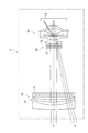
図1に示されるように、撮像装置1は、第一レンズ群10と、第二レンズ群20と、第三レンズ群30と、撮像素子Sとを備える。
As shown in FIG. 1, the
第一レンズ群10、第二レンズ群20、及び第三レンズ群30は、撮像素子Sに対してそれぞれ位置決めされている。第一レンズ群10、第二レンズ群20、及び第三レンズ群30は、互いに位置決めされており、光路L1,L2が第一レンズ群10、第二レンズ群20、及び第三レンズ群30の順に通るように配置されている。光路L1及び光路L2は撮像装置1に入射する光の光路を表している。光路L1と光路L2とは第一レンズ群10に入射する入射角が異なる。
The
図1に示されるように、第一群主点M1、第二群主点M2、第三群主点M3は、同一の光軸上Lに位置している。第一群主点M1は第一レンズ群10の撮像素子S側の主点である。第二群主点M2は第二レンズ群20の撮像素子S側の主点である。第三群主点M3は第三レンズ群30の撮像素子S側の主点である。第一群主点M1と第二群主点M2との距離は、第二群主点M2と第三群主点M3との距離よりも長い。
As shown in FIG. 1, the first group principal point M1, the second group principal point M2, and the third group principal point M3 are located on the same optical axis L. The first group principal point M1 is a principal point on the imaging element S side of the
第一レンズ群10は少なくとも1つの第一液晶レンズ11を含んでいる。ここで、第一液晶レンズ11について説明する。第一液晶レンズ11は屈折率が調整可能な液晶レンズである。
The
まず、図2を参照して、第一液晶レンズ11として用いられる液晶レンズ11について説明する。図2に示されるように、液晶レンズ11は、液晶層LCが一対の透明基板CGに挟まれている。液晶レンズ11は液晶層LCの一方の面に共通電極EL1が配置されており、他方の面に外部電極EL2及び内部電極EL3が配置されている。
First, the
ここで、図3を参照して、液晶レンズ11の屈折率について説明する。図3は、液晶レンズ11に印加される電圧である印加電圧の違いを示している。図3の(a)は、外部電極EL2及び内部電極EL3による印加電圧がない場合の液晶レンズ11を模式的に示している。図3の(b)は、外部電極EL2による印加電圧が内部電極EL3によるに印加電圧よりも高い場合の液晶レンズ11を模式的に示している。図3の(c)は、外部電極EL2による印加電圧が内部電極EL3によるに印加電圧よりも低い場合の液晶レンズ11を模式的に示している。
Here, the refractive index of the
図3の(a)に示されるように、外部電極EL2と内部電極EL3とに電圧が印加されていない場合の、液晶レンズ11に入射された光は、液晶レンズ11による屈折の影響を受けない。このため、入射した光は屈折することなく透過する。
As shown in FIG. 3A, the light incident on the
図3の(b)に示されるように、外部電極EL2による印加電圧が内部電極EL3によるに印加電圧よりも高い場合、液晶レンズ11の中心からの距離が離れるほど液晶レンズ11の屈折率が小さくなるように液晶層LC内の液晶分子LMが制御される。このため、液晶レンズ11に入射された光は、液晶レンズ11の中心方向に向かって屈折する。従って、制御部はこのように印加電圧を制御することにより、レンズパワーの極性が正となるように液晶レンズ11を制御することができる。
As shown in FIG. 3B, when the applied voltage by the external electrode EL2 is higher than the applied voltage by the internal electrode EL3, the refractive index of the
図3の(c)に示されるように、外部電極EL2による印加電圧が内部電極EL3によるに印加電圧よりも低い場合、液晶レンズ11の中心からの距離が離れるほど液晶レンズ11の屈折率が大きくなるように液晶層LC内の液晶分子LMが制御される。このため、液晶レンズ11に入射された光は、液晶レンズ11の中心方向から広がるように屈折する。従って、制御部はこのように印加電圧を制御することにより、レンズパワーの極性が負となるように液晶レンズ11を制御することができる。
As shown in FIG. 3C, when the applied voltage by the external electrode EL2 is lower than the applied voltage by the internal electrode EL3, the refractive index of the
次に、図4を参照して、第三液晶レンズ31として用いられる液晶レンズ31について説明する。液晶レンズ31は、上述した液晶レンズ11と同様の構成を備え、液晶レンズ31の屈折率を調整する制御部32をさらに備える。制御部32は液晶レンズ31に印加する電圧を制御することにより、液晶レンズ31を所望のレンズパワーに調整できる。制御部32は、液晶レンズ31の四隅31a,31b,31c,31dに印加電圧を印加する制御を行う。
Next, the
さらに、図5に示されるように、制御部32が印加電圧を印加することにより、液晶レンズ31の液晶分子LMの配向を局所的に変化させる。このため、液晶レンズ31の焦点位置(結像位置)を撮像素子Sを通る平面上(x方向又はy方向)に制御することができる。また、液晶レンズ31の外部電極EL2及び内部電極EL3を局所的に変化させることにより、液晶レンズ31の焦点位置を液晶レンズ31に対して近づく方向(垂直な方向、z方向)に制御することができる。このように、焦点位置を制御できる液晶レンズ31としては、例えば、特開2006−91826号公報に記載されているタイプの液晶レンズを用いることができる。
Furthermore, as shown in FIG. 5, the
上述したように、第一レンズ群10は第一液晶レンズ11を含んでいる。第一液晶レンズ11の制御部によって第一液晶レンズ11のレンズパワーの極性を制御することにより、第一レンズ群10のレンズパワーの極性を制御することができる。
As described above, the
第二レンズ群20は少なくとも1つの第二液晶レンズ21を含んでいる。第二液晶レンズ21は屈折率が調整可能な液晶レンズである。第二液晶レンズ21は液晶レンズ11である。第二液晶レンズ21の制御部によって第二液晶レンズ21のレンズパワーの極性を制御することにより、第二レンズ群20のレンズパワーの極性を制御することができる。
The
第三レンズ群30は、少なくとも1つの固定レンズを含んでいる。第三レンズ群30は、例えば、複数の固定レンズを含んでいてもよい。
The
撮像素子Sは、レンズを通って入射してきた光を電気信号に変換する素子である。撮像素子Sは、例えばCCDやCMOS等の撮像素子である。撮像素子Sは配線と電気的に接続され、画像信号を出力してもよい。 The image sensor S is an element that converts light incident through the lens into an electrical signal. The image sensor S is an image sensor such as a CCD or CMOS. The image sensor S may be electrically connected to the wiring and output an image signal.
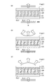
ここで、図6を参照して、本実施形態における液晶レンズによるズーム機能について説明する。図6は、従来技術においてズーム機能を実現するレンズ系100と本実施形態においてズーム機能を実現するレンズ系とを説明するための図である。図6の(A)及び図6の(B)は従来技術におけるズーム機能を実現するレンズ系100の構成を模式的に示している。図6の(C)及び図6の(D)は本実施形態においてズーム機能を実現するレンズ系の構成を模式的に示している。
Here, with reference to FIG. 6, the zoom function by the liquid crystal lens in this embodiment is demonstrated. FIG. 6 is a diagram for explaining a
図6の(A)は、レンズ系100において広角(wide)レンズとして機能するためのレンズの配置である。図6の(B)は、レンズ系100において望遠(tele)レンズとして機能するためのレンズの配置である。
6A shows the arrangement of lenses for functioning as a wide-angle lens in the
図6の(A)及び図6の(B)に示されるように、レンズ系100は、レンズ系100が複数の凹レンズ及び凸レンズで構成されている。広角レンズとして機能していたレンズ系100を望遠レンズとして機能するレンズ系100にさせるためには、レンズ系100を構成するレンズを移動させることにより、レンズ系100全体の焦点位置を一定に保つ構成が必要であった。
As shown in FIGS. 6A and 6B, the
図6の(C)は、本実施形態において広角(wide)レンズとして機能するためのレンズの配置である。図6の(D)は、本実施形態において望遠(tele)レンズとして機能するためのレンズの配置である。 FIG. 6C shows a lens arrangement for functioning as a wide-angle lens in the present embodiment. FIG. 6D shows an arrangement of lenses for functioning as a tele lens in this embodiment.
液晶レンズ11は、第一レンズ群10のレンズパワーの極性と、第二レンズ群20のレンズパワーの極性とが逆になるように、第一液晶レンズ11のレンズパワーの極性及び第二液晶レンズ21のレンズパワーの極性を制御することができる。
The
図6の(C)に示されるように、制御部は、第一レンズ群10のレンズパワーの極性が負であり、第二レンズ群20のレンズパワーの極性が正であるように制御すると、より視野角の広い光路で進入した光路L1,L2を撮像素子Sに対して結像することができる。このため、第一レンズ群10、第二レンズ群20、及び第三レンズ群30は第一レンズ群10、第二レンズ群20、及び第三レンズ群30を通る光に対して広角レンズとして機能する。
As shown in (C) of FIG. 6, when the control unit performs control so that the lens power polarity of the
図6の(D)に示されるように、制御部は、第一レンズ群10のレンズパワーの極性が正であり、第二レンズ群20のレンズパワーの極性が負であるように制御すると、より遠方の被写体から進入した光路L1,L2を撮像素子Sに対して結像することができる。このため、第一レンズ群10、第二レンズ群20、及び第三レンズ群30は第一レンズ群10、第二レンズ群20、及び第三レンズ群30を通る光に対して望遠レンズとして機能する。
As shown in (D) of FIG. 6, when the control unit performs control so that the lens power polarity of the
以上説明したように、撮像装置1では、第一レンズ群10と、第二レンズ群20と、第三レンズ群30とが撮像素子Sに対して位置決めされているため、第一レンズ群10と、第二レンズ群20と、第三レンズ群30とが撮像素子Sに対して動かない。第一レンズ群10と、第二レンズ群20と、第三レンズ群30を移動させることなく像が撮像素子Sに結像される。第一群主点M1と第二群主点M2との距離が、第二群主点M2と第三群主点M3との距離よりも長いため、ズームの拡大倍率を変化させるためにレンズ群を光軸方向に機械的に移動させることなく、ズーム機能を実現することができる。
As described above, in the
さらに、制御部110により第一レンズ群10のレンズパワーの極性と第二レンズ群20のレンズパワーの極性とを制御することができる。例えば、第一レンズ群のレンズパワーの極性が負であり、第二レンズ群のレンズパワーの極性が正であるように制御した場合、第一レンズ群10、第二レンズ群20、及び第三レンズ群30は第一レンズ群10、第二レンズ群20、及び第三レンズ群30を通る光に対して広角レンズとして機能する。一方、第一レンズ群のレンズパワーの極性が正であり、第二レンズ群のレンズパワーの極性が負であるように制御した場合、第一レンズ群10、第二レンズ群20、及び第三レンズ群30は第一レンズ群10、第二レンズ群20、及び第三レンズ群30を通る光に対して望遠レンズとして機能する。レンズ系全体の焦点位置を一定に保ちながら連続的に焦点距離を変化させることが可能となる。
Further, the control unit 110 can control the lens power polarity of the
以上、第一実施形態によれば、高倍率のズーム機能を実現する撮像装置1を提供することができる。さらに、広角レンズと望遠レンズとの機能を無段階の倍率で実現することができる。
As mentioned above, according to 1st embodiment, the
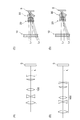
(第二実施形態)
図7を参照して、第二実施形態に係る撮像装置について説明する。第二実施形態に係る撮像装置1は、第一レンズ群10及び第二レンズ群20を除いて第一実施形態に係る撮像装置1と同様である。以下、第一実施形態との重複説明は省略し、相違点を中心に説明する。
(Second embodiment)
With reference to FIG. 7, an imaging apparatus according to the second embodiment will be described. The
図7は、第二実施形態に係る撮像装置1の構成を模式的に示す図である。
FIG. 7 is a diagram schematically illustrating the configuration of the
図7に示されるように、第一レンズ群10は第一液晶レンズ11以外にレンズ12を含んでいる。レンズ12全体のレンズパワーの極性は負である。第二レンズ群20は第二液晶レンズ21以外にレンズ22を含んでいる。レンズ22全体のレンズパワーの極性が正である。
As shown in FIG. 7, the
第二実施形態では、第一レンズ群10に入射して結像に寄与する光の画角を、第一実施形態よりも大きく許容することができる。このため、より高い倍率のズーム機能を達成するために、第一液晶レンズ11及び第二液晶レンズ21のサイズを大きくする必要がなくなる。よって、撮像装置1を小型化することができる。
In the second embodiment, the angle of view of light that enters the
以上、第二実施形態によれば、高倍率のズーム機能を実現するレンズをより小型化することが可能な撮像装置1が得られる。
As described above, according to the second embodiment, it is possible to obtain the
(第三実施形態)
図8を参照して、第三実施形態に係る撮像装置について説明する。第三実施形態に係る撮像装置1は、第三レンズ群30を除いて第二実施形態に係る撮像装置1と同様である。以下、第二実施形態との重複説明は省略し、相違点を中心に説明する。
(Third embodiment)
With reference to FIG. 8, the imaging apparatus according to the third embodiment will be described. The
図8は、第三実施形態に係る撮像装置1の構成を模式的に示す図である。
FIG. 8 is a diagram schematically illustrating a configuration of the
図8に示されるように、第三レンズ群30は少なくとも1つの第三液晶レンズ31を含んでいる。第三液晶レンズ31は屈折率が調整可能な液晶レンズである。第三液晶レンズ31は液晶レンズ31である。第三液晶レンズ31は制御部32によって第三液晶レンズ31のレンズパワー及びその極性を制御することにより、第三レンズ群30のレンズパワーを制御する。制御部110は撮像素子Sに対する結像位置が移動するように第三液晶レンズ31に印加される印加電圧を制御する。
As shown in FIG. 8, the
第三実施形態では、第三レンズ群30の焦点距離が制御されるため、被写体の遠近の違いによって生じる第三レンズ群の出射光の結像位置の微小な変動に対して、第三レンズ群に含まれる第三液晶レンズのレンズパワーの働きにより、結像位置を撮像素子の撮像面に対して垂直な方向に制御することができる。従って、結像位置を制御する機能、すなわち、焦点調整(フォーカシング)機能を実現することができる。結像位置を撮像素子Sの撮像面内で移動させることにより手振補正を行うことができる。
In the third embodiment, since the focal length of the
以上、第三実施形態によれば、高倍率のズーム機能を実現しつつ、焦点調整機能及び手振補正機能を備える撮像装置1が得られる。
As described above, according to the third embodiment, it is possible to obtain the
(第四実施形態)
図9を参照して、第四実施形態に係る撮像装置について説明する。第四実施形態に係る撮像装置1は、第一反射部材41を備える点を除いて第二実施形態に係る撮像装置1と同様である。以下、第二実施形態との重複説明は省略し、相違点を中心に説明する。
(Fourth embodiment)
An imaging apparatus according to the fourth embodiment will be described with reference to FIG. The
図9は、第四実施形態に係る撮像装置1の構成を模式的に示す図である。
FIG. 9 is a diagram schematically illustrating the configuration of the
図9に示されるように、第一レンズ群10と第二レンズ群20との間に光の光路を反射させる第一反射部材41が設けられていている。
As shown in FIG. 9, a first reflecting
第四実施形態では、第一レンズ群10に入射された光の光路L1,L2,L3は第一反射部材41により曲げられる。このため、第一レンズ群10に入射された光の光軸に沿って見たときに、撮像装置1の大きさを小さくすることができる。
In the fourth embodiment, the
以上、第四実施形態によれば、高倍率のズーム機能を実現しつつ、撮像装置1を低背化することができる。
As described above, according to the fourth embodiment, it is possible to reduce the height of the
(第五実施形態)
図10を参照して、第五実施形態に係る撮像装置について説明する。第五実施形態に係る撮像装置1は、第一反射部材41及び第二反射部材42を備える点を除いて第二実施形態に係る撮像装置1と同様である。以下、第二実施形態との重複説明は省略し、相違点を中心に説明する。
(Fifth embodiment)
With reference to FIG. 10, an imaging apparatus according to the fifth embodiment will be described. The
図10は、第五実施形態に係る撮像装置1の構成を模式的に示す図である。
FIG. 10 is a diagram schematically illustrating a configuration of the
図10に示されるように、第一レンズ群10と第二レンズ群20との間に光の光路を反射させる第一反射部材41及び第二反射部材42が配置されている。
As shown in FIG. 10, a first reflecting
第五実施形態では、第一レンズ群10に入射された光の光路L1,L2,L3は第一反射部材41により曲げられる。第二反射部材42は、第二反射部材42に入射する光の光路を第一レンズ群10が配置される側に反射する。
In the fifth embodiment, the
第一反射部材41及び第二反射部材42は、第一反射部材41に入射する光の入射角と、第二反射部材42が反射する光の反射角とが異なるように、配置されていてもよい。この場合、第一反射部材41と第二反射部材42は、第一レンズ群10に入射する光の光軸と垂直な平面に対して異なる角度で配置される。
The first reflecting
このため、第一レンズ群10に入射された光の光軸に沿って見たときに、撮像装置1の大きさを小さくすることができる。
For this reason, the size of the
以上、第五実施形態によれば、高倍率のズーム機能を実現しつつ、撮像装置1を小型化かつ低背化することができる。
As described above, according to the fifth embodiment, it is possible to reduce the size and height of the
以上、本発明の実施形態について説明してきたが、本発明はこうした実施形態に何等限定されるものではなく、本発明の要旨を逸脱しない範囲内において種々なる態様で実施し得る。 As mentioned above, although embodiment of this invention was described, this invention is not limited to such embodiment at all, In the range which does not deviate from the summary of this invention, it can implement with a various aspect.
例えば、上述した第四実施形態及び第五実施形態において、第三レンズ群30が第三液晶レンズ31を備えていてもよい。この場合、焦点調整(フォーカシング)機能または手振補正機能を備えつつ、撮像装置1を低背化することができる。
For example, in the fourth embodiment and the fifth embodiment described above, the
上述した実施形態において、第一液晶レンズ11のレンズパワーの極性を制御する制御手段、第二液晶レンズ21のレンズパワーの極性を制御する制御手段、及び第三液晶レンズ31のレンズパワーの極性を制御する制御手段は、第一液晶レンズ11、第二液晶レンズ21、及び第三液晶レンズ31にそれぞれ備えられていてもよい。この場合であっても、上述した作用・効果を奏することができる。
In the embodiment described above, the control means for controlling the lens power polarity of the first
1…撮像装置、10…第一レンズ群、11…第一液晶レンズ、20…第二レンズ群、21…第二液晶レンズ、30…第三レンズ群、31…第三液晶レンズ、41…第一反射部材、42…第二反射部材、M1…第一群主点、M2…第二群主点、M3…第三群主点、S…撮像素子。
DESCRIPTION OF
Claims (9)
少なくとも1つの第二液晶レンズを含む第二レンズ群と、
少なくとも1つの固定レンズを含む第三レンズ群と、
前記第三レンズ群を通過した光を受光し、受光した光を電気信号に変換する撮像素子と、
を備え、
前記第一レンズ群、前記第二レンズ群、及び前記第三レンズ群は、互いに位置決めされ、かつ、光が前記第一レンズ群、前記第二レンズ群、及び前記第三レンズ群の順に通るように配置され、
前記第一レンズ群の前記撮像素子側の主点である第一群主点、前記第二レンズ群の前記撮像素子側の主点である第二群主点、及び前記第三レンズ群の前記撮像素子側の主点である第三群主点は、同一の光軸上に位置し、前記第一群主点と前記第二群主点との距離が、前記第二群主点と前記第三群主点との距離よりも長いことを特徴とする撮像装置。 A first lens group including at least one first liquid crystal lens;
A second lens group including at least one second liquid crystal lens;
A third lens group including at least one fixed lens;
An image sensor that receives light that has passed through the third lens group, and converts the received light into an electrical signal;
With
The first lens group, the second lens group, and the third lens group are positioned with respect to each other, and light passes through the first lens group, the second lens group, and the third lens group in this order. Placed in
A first group principal point that is a principal point on the image sensor side of the first lens group, a second group principal point that is a principal point on the image sensor side of the second lens group, and the third lens group The third group principal point that is the principal point on the image sensor side is located on the same optical axis, and the distance between the first group principal point and the second group principal point is the second group principal point and the second group principal point. An imaging apparatus characterized by being longer than the distance from the third group principal point.
前記第二液晶レンズ以外の前記第二レンズ群に含まれるレンズは、前記第二液晶レンズ以外のレンズ全体のレンズパワーの極性が正であることを特徴とする請求項1〜3のいずれか一項に記載の撮像装置。 The lens included in the first lens group other than the first liquid crystal lens has a negative polarity of the lens power of the entire lens other than the first liquid crystal lens,
The lens included in the second lens group other than the second liquid crystal lens has positive polarity of the lens power of the entire lens other than the second liquid crystal lens. The imaging device according to item.
前記第三液晶レンズのレンズパワーの極性を制御する制御手段をさらに備えることを特徴とする請求項1〜4のいずれか一項に記載の撮像装置。 The third lens group includes at least one third liquid crystal lens;
The imaging apparatus according to claim 1, further comprising a control unit that controls a polarity of lens power of the third liquid crystal lens.
Priority Applications (1)
| Application Number | Priority Date | Filing Date | Title |
|---|---|---|---|
| JP2013094075A JP2014215519A (en) | 2013-04-26 | 2013-04-26 | Image-capturing device |
Applications Claiming Priority (1)
| Application Number | Priority Date | Filing Date | Title |
|---|---|---|---|
| JP2013094075A JP2014215519A (en) | 2013-04-26 | 2013-04-26 | Image-capturing device |
Publications (1)
| Publication Number | Publication Date |
|---|---|
| JP2014215519A true JP2014215519A (en) | 2014-11-17 |
Family
ID=51941304
Family Applications (1)
| Application Number | Title | Priority Date | Filing Date |
|---|---|---|---|
| JP2013094075A Pending JP2014215519A (en) | 2013-04-26 | 2013-04-26 | Image-capturing device |
Country Status (1)
| Country | Link |
|---|---|
| JP (1) | JP2014215519A (en) |
Citations (5)
| Publication number | Priority date | Publication date | Assignee | Title |
|---|---|---|---|---|
| JPS61103116A (en) * | 1984-10-26 | 1986-05-21 | Olympus Optical Co Ltd | View angle varying device for endoscope |
| JPH0289017A (en) * | 1988-09-26 | 1990-03-29 | Olympus Optical Co Ltd | Image pickup system |
| JPH11317894A (en) * | 1998-03-05 | 1999-11-16 | Olympus Optical Co Ltd | Optical device |
| JP2000081573A (en) * | 1998-06-30 | 2000-03-21 | Olympus Optical Co Ltd | Optical system and image pickup device |
| JP2008268700A (en) * | 2007-04-24 | 2008-11-06 | Konica Minolta Opto Inc | Lens barrel and imaging apparatus |
-
2013
- 2013-04-26 JP JP2013094075A patent/JP2014215519A/en active Pending
Patent Citations (5)
| Publication number | Priority date | Publication date | Assignee | Title |
|---|---|---|---|---|
| JPS61103116A (en) * | 1984-10-26 | 1986-05-21 | Olympus Optical Co Ltd | View angle varying device for endoscope |
| JPH0289017A (en) * | 1988-09-26 | 1990-03-29 | Olympus Optical Co Ltd | Image pickup system |
| JPH11317894A (en) * | 1998-03-05 | 1999-11-16 | Olympus Optical Co Ltd | Optical device |
| JP2000081573A (en) * | 1998-06-30 | 2000-03-21 | Olympus Optical Co Ltd | Optical system and image pickup device |
| JP2008268700A (en) * | 2007-04-24 | 2008-11-06 | Konica Minolta Opto Inc | Lens barrel and imaging apparatus |
Similar Documents
| Publication | Publication Date | Title |
|---|---|---|
| KR102083931B1 (en) | Wide angle lens system | |
| US10359608B2 (en) | Bifocal lens and imaging device including same | |
| TWI420140B (en) | Zoom camera module | |
| TWI475245B (en) | Optics lens assembly for image capture and image capture device thereof | |
| TW200835931A (en) | Zoom lens and imaging apparatus | |
| JP5657749B2 (en) | Zoom lens and zoom lens module | |
| US20130027522A1 (en) | Stereoscopic imaging apparatus | |
| JP7087000B2 (en) | A method for providing a multi-aperture image pickup device, an imaging system, and a multi-aperture image pickup device. | |
| JP2006251613A (en) | Imaging lens device | |
| JP2011133739A5 (en) | ||
| JP2013254020A5 (en) | ||
| CN107843978B (en) | Zoom lens, image pickup apparatus, and lens | |
| JP6383505B2 (en) | Optical system having a lens including regions with different characteristics | |
| US8520313B2 (en) | Zoom lens and image pickup device including the same | |
| US20230273412A1 (en) | Camera module | |
| CN113302536B (en) | Image capturing apparatus | |
| KR20170089185A (en) | Zoom Optical System | |
| JP2014215519A (en) | Image-capturing device | |
| KR20180037170A (en) | Zoom Optical System | |
| CN112005151B (en) | Camera module and optical device | |
| JP2007065151A (en) | Imaging lens | |
| KR20220008573A (en) | Lens optical system and camera module having thereof | |
| JP5290902B2 (en) | Zoom lens | |
| CN113302535A (en) | Image capturing apparatus | |
| CN113302534A (en) | Optical system, optical device, imaging apparatus, and method for manufacturing optical system and imaging apparatus |
Legal Events
| Date | Code | Title | Description |
|---|---|---|---|
| A131 | Notification of reasons for refusal |
Free format text: JAPANESE INTERMEDIATE CODE: A131 Effective date: 20150324 |
|
| A977 | Report on retrieval |
Free format text: JAPANESE INTERMEDIATE CODE: A971007 Effective date: 20150325 |
|
| A02 | Decision of refusal |
Free format text: JAPANESE INTERMEDIATE CODE: A02 Effective date: 20150714 |