EP4067765B1 - Air-conditioning system and method for controlling same - Google Patents
Air-conditioning system and method for controlling same Download PDFInfo
- Publication number
- EP4067765B1 EP4067765B1 EP19954508.8A EP19954508A EP4067765B1 EP 4067765 B1 EP4067765 B1 EP 4067765B1 EP 19954508 A EP19954508 A EP 19954508A EP 4067765 B1 EP4067765 B1 EP 4067765B1
- Authority
- EP
- European Patent Office
- Prior art keywords
- flow
- heat
- heat medium
- indoor
- indoor unit
- Prior art date
- Legal status (The legal status is an assumption and is not a legal conclusion. Google has not performed a legal analysis and makes no representation as to the accuracy of the status listed.)
- Active
Links
Images

Classifications
-
- F—MECHANICAL ENGINEERING; LIGHTING; HEATING; WEAPONS; BLASTING
- F25—REFRIGERATION OR COOLING; COMBINED HEATING AND REFRIGERATION SYSTEMS; HEAT PUMP SYSTEMS; MANUFACTURE OR STORAGE OF ICE; LIQUEFACTION SOLIDIFICATION OF GASES
- F25B—REFRIGERATION MACHINES, PLANTS OR SYSTEMS; COMBINED HEATING AND REFRIGERATION SYSTEMS; HEAT PUMP SYSTEMS
- F25B13/00—Compression machines, plants or systems, with reversible cycle
-
- F—MECHANICAL ENGINEERING; LIGHTING; HEATING; WEAPONS; BLASTING
- F24—HEATING; RANGES; VENTILATING
- F24F—AIR-CONDITIONING; AIR-HUMIDIFICATION; VENTILATION; USE OF AIR CURRENTS FOR SCREENING
- F24F11/00—Control or safety arrangements
- F24F11/30—Control or safety arrangements for purposes related to the operation of the system, e.g. for safety or monitoring
- F24F11/32—Responding to malfunctions or emergencies
-
- F—MECHANICAL ENGINEERING; LIGHTING; HEATING; WEAPONS; BLASTING
- F24—HEATING; RANGES; VENTILATING
- F24F—AIR-CONDITIONING; AIR-HUMIDIFICATION; VENTILATION; USE OF AIR CURRENTS FOR SCREENING
- F24F11/00—Control or safety arrangements
- F24F11/30—Control or safety arrangements for purposes related to the operation of the system, e.g. for safety or monitoring
- F24F11/32—Responding to malfunctions or emergencies
- F24F11/36—Responding to malfunctions or emergencies to leakage of heat-exchange fluid
-
- F—MECHANICAL ENGINEERING; LIGHTING; HEATING; WEAPONS; BLASTING
- F24—HEATING; RANGES; VENTILATING
- F24F—AIR-CONDITIONING; AIR-HUMIDIFICATION; VENTILATION; USE OF AIR CURRENTS FOR SCREENING
- F24F11/00—Control or safety arrangements
- F24F11/30—Control or safety arrangements for purposes related to the operation of the system, e.g. for safety or monitoring
- F24F11/41—Defrosting; Preventing freezing
- F24F11/43—Defrosting; Preventing freezing of indoor units
-
- F—MECHANICAL ENGINEERING; LIGHTING; HEATING; WEAPONS; BLASTING
- F24—HEATING; RANGES; VENTILATING
- F24F—AIR-CONDITIONING; AIR-HUMIDIFICATION; VENTILATION; USE OF AIR CURRENTS FOR SCREENING
- F24F11/00—Control or safety arrangements
- F24F11/70—Control systems characterised by their outputs; Constructional details thereof
- F24F11/72—Control systems characterised by their outputs; Constructional details thereof for controlling the supply of treated air, e.g. its pressure
- F24F11/74—Control systems characterised by their outputs; Constructional details thereof for controlling the supply of treated air, e.g. its pressure for controlling air flow rate or air velocity
-
- F—MECHANICAL ENGINEERING; LIGHTING; HEATING; WEAPONS; BLASTING
- F24—HEATING; RANGES; VENTILATING
- F24F—AIR-CONDITIONING; AIR-HUMIDIFICATION; VENTILATION; USE OF AIR CURRENTS FOR SCREENING
- F24F11/00—Control or safety arrangements
- F24F11/70—Control systems characterised by their outputs; Constructional details thereof
- F24F11/80—Control systems characterised by their outputs; Constructional details thereof for controlling the temperature of the supplied air
- F24F11/83—Control systems characterised by their outputs; Constructional details thereof for controlling the temperature of the supplied air by controlling the supply of heat-exchange fluids to heat-exchangers
- F24F11/85—Control systems characterised by their outputs; Constructional details thereof for controlling the temperature of the supplied air by controlling the supply of heat-exchange fluids to heat-exchangers using variable-flow pumps
-
- F—MECHANICAL ENGINEERING; LIGHTING; HEATING; WEAPONS; BLASTING
- F24—HEATING; RANGES; VENTILATING
- F24F—AIR-CONDITIONING; AIR-HUMIDIFICATION; VENTILATION; USE OF AIR CURRENTS FOR SCREENING
- F24F11/00—Control or safety arrangements
- F24F11/70—Control systems characterised by their outputs; Constructional details thereof
- F24F11/80—Control systems characterised by their outputs; Constructional details thereof for controlling the temperature of the supplied air
- F24F11/86—Control systems characterised by their outputs; Constructional details thereof for controlling the temperature of the supplied air by controlling compressors within refrigeration or heat pump circuits
-
- F—MECHANICAL ENGINEERING; LIGHTING; HEATING; WEAPONS; BLASTING
- F24—HEATING; RANGES; VENTILATING
- F24F—AIR-CONDITIONING; AIR-HUMIDIFICATION; VENTILATION; USE OF AIR CURRENTS FOR SCREENING
- F24F3/00—Air-conditioning systems in which conditioned primary air is supplied from one or more central stations to distributing units in the rooms or spaces where it may receive secondary treatment; Apparatus specially designed for such systems
- F24F3/06—Air-conditioning systems in which conditioned primary air is supplied from one or more central stations to distributing units in the rooms or spaces where it may receive secondary treatment; Apparatus specially designed for such systems characterised by the arrangements for the supply of heat-exchange fluid for the subsequent treatment of primary air in the room units
- F24F3/065—Air-conditioning systems in which conditioned primary air is supplied from one or more central stations to distributing units in the rooms or spaces where it may receive secondary treatment; Apparatus specially designed for such systems characterised by the arrangements for the supply of heat-exchange fluid for the subsequent treatment of primary air in the room units with a plurality of evaporators or condensers
-
- F—MECHANICAL ENGINEERING; LIGHTING; HEATING; WEAPONS; BLASTING
- F25—REFRIGERATION OR COOLING; COMBINED HEATING AND REFRIGERATION SYSTEMS; HEAT PUMP SYSTEMS; MANUFACTURE OR STORAGE OF ICE; LIQUEFACTION SOLIDIFICATION OF GASES
- F25B—REFRIGERATION MACHINES, PLANTS OR SYSTEMS; COMBINED HEATING AND REFRIGERATION SYSTEMS; HEAT PUMP SYSTEMS
- F25B49/00—Arrangement or mounting of control or safety devices
- F25B49/02—Arrangement or mounting of control or safety devices for compression type machines, plants or systems
- F25B49/022—Compressor control arrangements
-
- F—MECHANICAL ENGINEERING; LIGHTING; HEATING; WEAPONS; BLASTING
- F25—REFRIGERATION OR COOLING; COMBINED HEATING AND REFRIGERATION SYSTEMS; HEAT PUMP SYSTEMS; MANUFACTURE OR STORAGE OF ICE; LIQUEFACTION SOLIDIFICATION OF GASES
- F25B—REFRIGERATION MACHINES, PLANTS OR SYSTEMS; COMBINED HEATING AND REFRIGERATION SYSTEMS; HEAT PUMP SYSTEMS
- F25B2313/00—Compression machines, plants or systems with reversible cycle not otherwise provided for
- F25B2313/003—Indoor unit with water as a heat sink or heat source
Definitions
- the present invention relates to an air-conditioning system in which a heat source apparatus and a plurality of indoor units are connected via a relay device, and to a method of controlling the air-conditioning system.
- An air-conditioning system in which a plurality of indoor units individually perform a heating operation or a cooling operation has a refrigerant circuit and a structure in which heating energy, cooling energy, or both heating energy and cooling energy that are produced by a heat source apparatus, for example, are efficiently supplied to a plurality of loads.
- Such an air-conditioning system is adopted as, for example, a central air-conditioning system for use in, for example, a building or a hotel that has a large number of air-conditioned spaces.
- a heat source apparatus is installed outdoors, indoor units are installed indoors, and the heat source apparatus and the indoor units are connected via a relay device.
- a refrigerant pipe through which refrigerant circulates is provided between the heat source apparatus and the relay device, and heat medium pipes through which a heat medium, such as water or brine, circulates, are provided between the relay device and the respective indoor units.
- a heat medium such as water or brine
- the air-conditioning system in the case where an outage of a heat medium occurs in an indoor unit because of occurrence of a failure, such as freezing of an indoor heat exchanger, if the operation of the indoor unit continues, there is a possibility that a failure, such as non-cooling or non-heating, may occur. This is because the air-conditioning system does not have a function of detecting a water outage of each of the indoor units, although the air-conditioning system can detect a water outage at the entire heat-medium pipes that connect detect the indoor units and the relay unit that is located on the secondary side in a region between the heat source apparatus and the relay unit.
- an air-conditioning system includes a sensor that detects a state of an air-conditioned space that is a parameter for controlling air-conditioning, and a plurality of adjustment devices each of which adjusts the flow rate of a heat medium supplied to the air-conditioned space based on information from the sensor (see Japanese Unexamined Patent Application Publication No. 2005-249238 , for example).
- the sensor and the plurality of adjustment devices are collectively controlled, a collective control device that controls the supply flow rate of a heat medium is provided, the respective adjustment devices and the collective control device are capable of wirelessly communicating with each other, and the volume of cooling/heating air or the flow rate of cooling/heating water of an air-conditioning apparatus is controlled. Therefore, in the air-conditioning system disclosed in Japanese Unexamined Patent Application Publication No. 2005-249238 , it is possible to detect occurrence of a water outage at each of the indoor units.
- an air-conditioning apparatus is provided with a heat-source device that supplies a refrigerant, a relay unit that exchanges heat of a heat medium such as water or anti-freezing fluid supplied from the heat-source device in an intermediate heat exchanger and supplies the heat medium, an indoor unit that exchanges heat between a use side heat exchanger through which the heat medium supplied from the relay unit flows and indoor air and performs cooling or heating in the indoor space, a controller that controls operations of the heat-source device, the relay unit and the indoor unit, and a third temperature sensor that detects the temperature of the heat medium flowing through the use side heat exchanger, and if an abnormality in at least one of the heat-source device and the relay unit is detected, the controller continues the operation of the indoor unit while the temperature detected by the third temperature sensor remains within a first predetermined temperature range.
- a heat medium such as water or anti-freezing fluid supplied from the heat-source device in an intermediate heat exchanger and supplies the heat medium
- an indoor unit that exchanges heat between a use side heat exchanger through which the
- WO 2013/108290 A1 states an air conditioner provided with: a refrigeration cycle circuit configured by connecting by pipes one or multiple intermediary heat exchangers which exchange heat between a heat source-side refrigerant and a heat medium different from the heat source-side refrigerant; a heat medium circulation circuit configured by connecting by pipes one or multiple pumps for circulating the heat medium for heat exchange by the intermediary heat exchangers, a use-side heat exchanger which exchanges heat between the heat medium and air in the space to be air-conditioned, and flow path switching valves which switch between allowing passage of a heated heat medium, or allowing passage of a cooled heat medium to the use-side heat exchanger; and a control device which, on the basis of the temperature at the heat medium inlet of the heat exchanger in the heat medium circulation circuit, calculates the actual temperature efficiency, and, on the basis of the temperature efficiency and a set reference temperature efficiency, performs processing for determining whether or not the flow amount of the heat medium in the heat medium circulation circuit is abnormal.
- a refrigeration cycle circuit configured by connecting
- WO 2010/050001 A1 states that a heat source-side heat exchanger, intermediate heat exchangers, and a utilization-side heat exchanger are constructed separately from each other so that they can be placed at positions separated from each other.
- Flow path switching valves are provided on the entrance side and the exit side, respectively, of a heat medium flow path of the utilization-side heat exchanger. The flow path switching valves switch flow paths to connect the utilization-side heat exchanger to each intermediate heat exchanger.
- a pump for circulating a heat medium in a heat medium circulation circuit is provided either in a flow path between the utilization-side heat exchanger and the flow path switching valve placed on the entrance side of the utilization-side heat exchanger or in a flow path between the utilization-side heat exchanger and the flow path switching valve placed on the exit side of the utilization-side heat exchanger.
- WO 2013/061365 A1 states that obtained is an air conditioning device configured so that the noise of the flow of a refrigerant can be reduced irrespective of the state of the refrigerant at the inlet of an expansion mechanism.
- An air conditioning device is characterized in that an opening-closing valve which opens and closes a refrigerant flow path and a throttle mechanism which has a porous body through which the refrigerant can pass are connected in series so as to be parallel to a flow rate adjustment valve and in that, when the degree of opening of the flow rate adjustment valve is greater than that in a fully closed state of the valve and less than a predetermined degree of opening, a control device opens the opening-closing valve, and when the degree of opening of the expansion valve is greater than or equal to the predetermined degree of opening, the control device closes the opening-closing valve.
- WO 2017/221383 A1 states that provided is a heat medium circulation system that utilizes a heat medium pressure difference obtained from detection values of an entrance pressure sensor and an exit pressure sensor respectively disposed at the entrance and the exit of a heat medium heat exchanger so as to prevent the heat medium from freezing within the heat medium heat exchanger, thereby enabling continuous operation.
- This heat medium circulation system is provided with a refrigeration cycle circuit and a heat medium circulation circuit, and has: an entrance temperature sensor; an entrance pressure sensor; an exit pressure sensor; an evaporation temperature detection sensor; and a control device that, in the case of a first condition under which freeze of the heat medium takes place within the heat medium heat exchanger, calculates an operation-time minimum flow volume that does not result in freeze of the heat medium within the heat medium heat exchanger, on the basis of a heat medium temperature detected at the heat medium entrance by the entrance temperature sensor and a refrigerant evaporation temperature detected by the evaporation temperature detection sensor, and controls a pump so as to operate at the operation-time minimum flow volume so that the heat medium pressure difference obtained from the detection values of the entrance pressure sensor and the exit pressure sensor becomes an operation-time minimum pressure difference.
- the present invention is applied to solve the above problem. According to the present invention, it is possible to specify an indoor unit in which an air outage occurs from among a plurality of indoor units on the basis of the flow rate of a heat medium, and also detect a failure, without constructing a new control system, by controlling the pump, the compressor, or the indoor unit. Furthermore, the present invention relates to an air-conditioning system that can solve, by stopping an indoor unit in which an abnormality occurs, a problem that a failure, such as non-cooling or non-heating, would occur if the indoor unit continued to operate, and also to a method of controlling the air-conditioning system.
- flow-rate information detected by the flow-rate detection devices is abnormal flow-rate information indicating presence of a control target indoor unit which is an indoor unit to be controlled of the plurality of indoor units and in which a flow of the heat medium is cut off
- the operation of at least one of the compressor, the pump, or the control target indoor unit is controlled, and it is therefore possible to detect a failure without constructing a new control system.
- by stopping the indoor unit in which an abnormality occurs it is possible to solve a problem in which a failure, such as non-cooling or non-heating, would occur when such an indoor unit continued to operate.
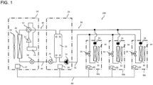
- Fig. 1 is a circuit diagram illustrating an air-conditioning system 100 according to Embodiment 1.
- the air-conditioning system 100 will be described with reference to Fig. 1 .
- the air-conditioning system 100 includes a heat source apparatus 10, a relay device 20, and a plurality of indoor units 30a, 30b, and 30c.
- Embodiment 1 will be described by referring to by way of example the case where three indoor units 30a, 30b, and 30c are connected to one heat source apparatus 10.
- the number of heat source apparatuses 10 may be two or more.
- the number of indoor units may be three or more.
- the plurality of indoor units 30a, 30b, and 30c may have the same capacity or may have different capacities.
- the air-conditioning system 100 is configured such that the heat source apparatus 10, the relay device 20, and the indoor units 30a, 30b, and 30c are connected.
- the heat source apparatus 10 has a function of suppling heating energy or cooling energy to the three indoor units 30a, 30b, and 30c via the relay device 20.
- the three indoor units 30a, 30b, and 30c are connected in parallel, and have the same configuration.
- Each of the indoor units 30a, 30b, and 30c has a function of performing a cooling operation or a heating operation in an associated room, which is an air-conditioned space, with heating energy or cooling energy supplied from the heat source apparatus 10.
- the relay device 20 is interposed between the heat source apparatus 10 and the indoor units 30a, 30b, and 30c, and has a function of switching the flow of refrigerant supplied from the heat source apparatus 10 in response to a request from each of the indoor units 30a, 30b, and 30c.
- the heat source apparatus 10 includes a compressor 11 having a variable capacity, a flow switching valve 12, a heat-source-side heat exchanger 13, a heat-source-side expansion device 14, and an accumulator 15.
- the flow switching valve 12 switches the flow direction of refrigerant in the heat source apparatus 10.
- the heat-source-side heat exchanger 13 serves as an evaporator or a condenser.
- the heat source apparatus 10 also includes a heat-source-side fan 16 and a heat-source-side control device 17.
- the heat-source-side fan 16 sends outside air to the heat-source-side heat exchanger 13.
- the heat-source-side control device 17 controls the operation of the heat source apparatus 10.
- the compressor 11 includes a compressor motor that is driven by an inverter, for example.
- the compressor 11 sucks and compresses refrigerant.
- the flow switching valve 12 is connected to the compressor 11, and is controlled by the heat-source-side control device 17 to switch the flow passage for refrigerant.
- the heat-source-side fan 16 varies the amount of air that is sent to the heat-source-side heat exchanger 13, to control a heat exchange capacity.
- the heat-source-side control device 17 controls operations of the compressor 11, the flow switching valve 12, and the heat-source-side expansion device 14.
- the heat-source-side control device 17 can communicate in data with a relay control device 24 of the relay device 20 and with an indoor-side control device 35 of each of the indoor units 30a, 30b, and 30c.
- the flow switching valve 12 is a four-way valve
- the flow switching valve 12 may be formed by combining two-way valves, three-way valves, or other valves.
- the heat source apparatus 10 performs a defrosting operation.
- the relay device 20 includes an inter-medium heat exchanger 21, a relay expansion device 22, a pump 23, and the relay control device 24.
- the relay device 20 is interposed between the heat source apparatus 10 and the indoor units 30a, 30b, and 30c.
- the relay device 20 has a function of switching the flow of refrigerant supplied from the heat source apparatus 10, in response to a request from each of the indoor units 30a, 30b, and 30c, and distributing heating energy or cooling energy supplied from the heat source apparatus 10 to the plurality of indoor units 30a, 30b, and 30c.
- the air-conditioning system 100 includes a refrigerant circuit 40 in which refrigerant circulates.
- the compressor 11, the flow switching valve 12, the heat-source-side heat exchanger 13, the heat-source-side expansion device 14, the relay expansion device 22, the inter-medium heat exchanger 21, and the accumulator 15 are provided, and are connected by refrigerant pipes 41. That is, the heat source apparatus 10 and the relay device 20 are connected by the refrigerant pipe 41.
- the inter-medium heat exchanger 21 is, for example, a plate type heat exchanger, and is connected between the refrigerant circuit 40 and a heat medium circuit 50, which will be described later.
- the inter-medium heat exchanger 21 causes heat exchange to be performed between the refrigerant that circulates in the refrigerant circuit 40 and a heat medium that circulates in the heat medium circuit 50.
- the relay expansion device 22 is, for example, an electronic expansion valve, and decompresses the refrigerant to expand the refrigerant.
- the relay expansion device 22 is provided between the heat-source-side heat exchanger 13 and the inter-medium heat exchanger 21 in the refrigerant circuit 40.
- the pump 23 includes a motor (not illustrated) that is driven by an inverter, for example.
- the pump 23 is driven by the motor, which serves as a power source, and causes the heat medium in the heat medium circuit 50 to circulate. That is, the pump 23 is controlled by the relay control device 24, and applies a pressure to cause the heat medium to circulate in the heat medium circuit 50.
- the relay control device 24 controls operations of the relay expansion device 22 and the pump 23.
- the relay control device 24 can control operations of the compressor 11 and the heat-source-side expansion device 14 via the heat-source-side control device 17.
- the relay control device 24 controls the operations of the compressor 11 and the pump 23 in conjunction with the heat-source-side control device 17 and each indoor-side control device 35 to improve an energy efficiency. That is, the relay control device 24 performs a centralized control of the air-conditioning system 100.
- Each of the indoor units 30a, 30b, and 30c is, for example, a fan coil unit, and is provided with the flow switch 31, which serves as a flow-rate detection device.
- Each of the indoor units 30a, 30b, and 30c includes an indoor-side heat exchanger 32 and a flow control valve 33.
- the indoor-side heat exchanger 32 serves as a condenser or an evaporator.
- the flow control valve 33 adjusts the flow rate of the heat medium.
- Each of the indoor units 30a, 30b, and 30c also includes an indoor-side fan 34 and the indoor-side control device 35.
- the indoor-side fan 34 sends indoor air to the indoor-side heat exchanger 32.
- the indoor units 30a, 30b, and 30c have a function of performing the cooling operation or the heating operation in a room, with cooling energy or heating energy supplied from the heat source apparatus 10.
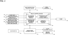
- Fig. 2 is a block diagram for use in explanation of the relay control device 24 of the air-conditioning system 100 according to Embodiment 1.
- the relay control device 24 includes a flow-rate arithmetic unit 241, a temperature-difference arithmetic unit 242, a capacity arithmetic unit 243, and a criterion flow-rate value storage unit 244.
- the flow-rate arithmetic unit 241 calculates the flow rate of the heat medium that circulates in the heat medium circuit 50 on the basis of a pressure difference obtained from the results of detection by a pump inlet pressure sensor 25 and a pump outlet pressure sensor 26.
- the pump inlet pressure sensor 25 is provided on the inlet side of the pump 23, and the pump outlet pressure sensor 26 is provided on the outlet side of the pump 23.
- the temperature-difference arithmetic unit 242 calculates a difference between temperatures of the heat medium that circulates in the heat medium circuit 50 before and after heat exchange, on the basis of the results of detection by a water inlet temperature sensor 27 and a water outlet temperature sensor 28.
- the water inlet temperature sensor 27 is provided on the inlet side of the inter-medium heat exchanger 21
- the water outlet temperature sensor 28 is provided on the outlet side of the inter-medium heat exchanger 21.
- the capacity arithmetic unit 243 calculates an operating capacity for cooling or heating by the heat medium which circulates such that the calculated temperature difference is made and circulates at the calculated flow rate.
- the capacity arithmetic unit 243 also calculates an operating capacity required for cooling or heating by the indoor units 30a to 30c, which are control targets.
- the capacity arithmetic unit 243 holds a threshold for the flow rate that is applied as a reference for determination whether to increase or decrease the rotation speed of the compressor 11.
- the capacity arithmetic unit 243 causes the heat-source-side control device 17 to decrease the frequency of the compressor 11.
- the capacity arithmetic unit 243 causes the heat-source-side control device 17 to increase the frequency of the compressor 11.
- the criterion flow-rate value storage unit 244 stores the threshold for flow rate which is applied as the reference for determination whether to increase or decrease the rotation speed of the pump 23 (which will hereinafter be referred to as "pump control threshold").
- pump control threshold two pump control thresholds are set as a first criterion flow-rate value and a second criterion flow-rate value.
- the first criterion flow-rate value is set for the case where a water outage occurs at two of the three indoor units 30a to 30c.
- the second criterion flow-rate value is set for a case where a water outage occurs at one of the three indoor units 30a to 30c.
- the criterion flow-rate value storage unit 244 stores a threshold for flow rate which is applied as a reference for determination whether to close the flow control valve 33 of each of the indoor units 30a, 30b, and 30c (which will hereinafter be referred to as "control valve threshold”).
- the criterion flow-rate value storage unit 244 also stores a threshold for the flow rate that is applied as a reference for determination whether to increase or decrease the rotation speed of the indoor-side fans 34 (which will hereinafter be referred to as "fan threshold").
- the relay control device 24 decreases an output of the pump 23.
- the pump 23 is stopped.
- the relay control device 24 controls the indoor-side control devices 35 based on the abnormal flow-rate information received from the heat-source-side control device 17.
- the indoor-side control device 35 controls at least one operation of the control target indoor unit that is the indoor unit 30a in the above case.
- the heat-source-side control device 17 controls the operation of the compressor 11. Furthermore, when receiving the abnormal flow-rate information detected by the flow switches 31, from the indoor-side control devices 35, the relay control device 24 controls the operation of the pump 23. Under these controls, it is possible to cause the heat medium to flow in the indoor units other than the control target indoor unit 30a, that is, the indoor units 30b and 30c, at a proper flow rate, and thus possible to prevent occurrence of a failure, such as non-cooling or non-heating, at the indoor units 30b and 30c.
- the air-conditioning system 100 has a cooling only operation and a heating only operation as operation modes.
- the cooling only operation is a mode where all of the indoor units 30a, 30b, and 30c perform the cooling operation.
- the heating only operation is a mode where all of the indoor units 30a, 30b, and 30c perform the heating operation.
- the cooling only operation will be described.
- all the indoor units 30a, 30b, and 30c perform the cooling operation.
- High-temperature and high-pressure gas refrigerant discharged from the compressor 11 passes through the flow switching valve 12, and flows into the heat-source-side heat exchanger 13.
- the high-temperature and high-pressure gas refrigerant exchanges heat with air that is sent by the heat-source-side fan 16, thereby condensing and liquefying.
- the heat-source-side fan 16 can vary the amount of air that the heat-source-side fan 16 sends.
- the refrigerant passes through the heat-source-side expansion device 14 and the relay expansion device 22 in this order, and flows into the inter-medium heat exchanger 21.
- the refrigerant that has flowed into the inter-medium heat exchanger 21 is decompressed to a low pressure by the heat-source-side control device 17 that is controlled based on a superheat amount on the outlet side of the inter-medium heat exchanger 21.
- the refrigerant that has been decompressed exchanges heat with a heat medium that circulates in the heat medium circuit 50, thereby evaporating and gasifying.
- rooms in which the indoor units 30a, 30b, and 30c are installed are cooled.
- the refrigerant that has gasified is sucked by the compressor 11 via the accumulator 15.
- the heat medium exchanges heat with the refrigerant that has been decompressed to a low pressure, and is thus cooled such that the heat medium is sufficiently subcooled.
- the heat medium then passes through the heat medium pipe 51 and flows into the indoor units 30a, 30b, and 30c when the indoor units 30a, 30b, and 30c are ready to perform the cooling operation.
- the heat-source-side control device 17 adjusts the capacity of the compressor 11 having a variable capacity and an air sending amount of the heat-source-side fan 16 that is the amount of air that the heat-source-side fan 16 sends, such that an evaporating temperature in the indoor units 30a, 30b, and 30c and a condensing temperature in the heat-source-side heat exchanger 13 reach respective target temperatures determined in advance. Therefore, each of the indoor units 30a, 30b, and 30c can obtain a target cooling capacity.
- the heating only operation will be described.
- all the indoor units 30a, 30b, and 30c perform the heating operation.
- High-temperature and high-pressure gas refrigerant discharged from the compressor 11 passes through the flow switching valve 12 and flows into the inter-medium heat exchanger 21.
- the refrigerant that has flowed into the inter-medium heat exchanger 21 exchanges heat with a heat medium that has exchanged heat with indoor air at each of the indoor-side heat exchangers 32, thereby condensing and liquefying.
- the refrigerant that has condensed and liquefied passes through the relay expansion device 22 and the heat-source-side expansion device 14 in this order, and is thus decompressed to change into low-pressure two-phase gas-liquid refrigerant.
- the low-pressure two-phase gas-liquid refrigerant flows into the heat-source-side heat exchanger 13, and is caused to exchange heat with air sent by the heat-source-side fan 16, which can vary the air sending amount thereof, thereby evaporating.
- the refrigerant that has evaporated and gasified is sucked by the compressor 11 via the flow switching valve 12 and the accumulator 15.
- the heat medium that has exchanged heat with the high-temperature and high-pressure gas refrigerant at the inter-medium heat exchanger 21 passes through the heat medium pipe 51 and flows into the indoor units 30a, 30b, and 30c that are ready to perform the heating operation.
- the heat-source-side control device 17 adjusts the capacity of the compressor 11 having a variable capacity and the air sending amount of the heat-source-side fan 16 such that an evaporating temperature in the indoor units 30a, 30b, and 30c and a condensing temperature in the heat-source-side heat exchanger 13 reach respective target temperatures determined in advance. Therefore, each of the indoor units 30a, 30b, and 30c can obtain a target heating capacity.
- FIG. 3 is a flowchart illustrating the operation of the air-conditioning system 100 according to Embodiment 1.
- the indoor-side control devices 35 confirm flow-rate information regarding the heat medium in the indoor units 30a, 30b, and 30c that is detected by the flow switches 31 (step S1). Then, it is determined whether the detected flow-rate information includes abnormal flow-rate information (information on water outage of the heat medium in Embodiment 1) indicating the presence of a control target indoor unit in which the flow of a heat medium is cut off, and which is one of the indoor units 30a, 30b, and 30c, that is, the control target indoor unit 30a in the above case.
- abnormal flow-rate information information on water outage of the heat medium in Embodiment 1
- step S2 When it is determined that the flow-rate information does not include abnormal flow-rate information (N in step S2), the process returns to step S1, and the flow switches 31 re-detect flow-rate information regarding the heat medium in the indoor units 30a, 30b, and 30c.
- the flow-rate information includes abnormal flow-rate information (Y in step S2)
- a control target indoor unit that is, the indoor unit 30a in the above case, in which the flow of a heat medium is cut off is present.
- the indoor-side fan 34 of the control target indoor unit 30a for which the abnormal flow-rate information is detected is stopped (step S3), and the flow control valve 33 of the control target indoor unit 30a for which the abnormal flow-rate information is detected is closed (step S4).
- a required flow rate of the heat medium in the indoor units 30b and 30c excluding the control target indoor unit 30a is calculated (step S5), and it is determined whether or not the required flow rate exceeds the second criterion flow-rate value that is a threshold for the flow rate of the heat medium that is determined in advance (step S6).
- the rotation speed of the pump is not adjusted, and the process proceeds to step S9 at which the frequency of the compressor is adjusted.
- step S6 When the required flow rate does not exceed the second criterion flow-rate value (step S6: Y), it is determined whether or not the required flow rate exceeds the first criterion flow-rate value that is another threshold for the flow rate of the heat medium that is determined in advance (step S7).
- step S7 When it is determined that the required flow rate does not exceed the first criterion flow-rate value (Y in step S7), the rotation speed of the pump 23 is reduced until the required flow rate reaches the first criterion flow-rate value (step S8).
- step S7 when the required flow rate exceeds the first criterion flow-rate value (N in step S7), the process shifts to step S14 at which the rotation speed of the pump 23 is reduced until the required flow rate reaches the second criterion flow-rate value.
- a difference between temperatures of the heat medium, which circulates through the heat medium circuit 50, at the outlet and the inlet of the inter-medium heat exchanger 21 is obtained from results of detection by the water inlet temperature sensor 27 and the water outlet temperature sensor 28 (step S9).
- the water inlet temperature sensor 27 is provided on the inlet side of the inter-medium heat exchanger 21, and the water outlet temperature sensor 28 is provided on the outlet side of the inter-medium heat exchanger 21.
- the flow rate of the heat medium that circulates in the heat medium circuit 50 is obtained from the results of detection by the pump inlet pressure sensor 25 and the pump outlet pressure sensor 26 (step S10).
- the pump inlet pressure sensor 25 is provided on the inlet side of the pump 23, and the pump outlet pressure sensor 26 is provided on the outlet side of the pump 23.
- the capacity arithmetic unit 243 calculates an operating capacity for cooling or heating by the heat medium, which circulates such that the calculated temperature difference is made and circulates at the calculated flow rate.
- the capacity arithmetic unit 243 also calculates an operating capacity required for cooling or heating at the indoor units 30b and 30c. Then, it is determined whether or not the operating capacity for cooling or heating by the heat medium, which is subjected to heat exchange such that the calculated temperature difference is made and circulates at the calculated flow rate, exceeds the operating capacity required for cooling or heating by the indoor units 30b and 30c (step S11).
- the heat-source-side control device 17 reduces the frequency of the compressor 11 (step S12).
- the heat-source-side control device 17 increases the frequency of the compressor 11 (step S13). Thereafter, the process returns to step S1, and the flow switches 31 re-detect flow-rate information regarding the heat medium in the indoor units 30a, 30b, and 30c.
- the heat medium it is possible to cause the heat medium to flow through the indoor units 30b and 30c excluding the control target indoor unit 30a, at a proper flow rate, and it is thus possible to prevent occurrence of a failure, such as non-cooling or non-heating, at the indoor units 30b and 30c.
- a failure such as non-cooling or non-heating
- the air-conditioning system 100 by performing the control according to the operation state of the entire air-conditioning system 100, it is possible to prevent occurrence of a failure without constructing a new control system and also to improve the energy efficiency.
- Embodiment 1 in the air-conditioning system 100 and the method of controlling the air-conditioning system 100, when flow-rate information detected by the flow switches 31 is abnormal flow-rate information indicating the presence of a control target indoor unit in which the flow of a heat medium is cut off, and which is one of the plurality of indoor units 30a, 30b, and 30c, that is, the indoor unit 30a in the above case, the relay control device 24 controls the indoor-side control devices 35 based on the abnormal flow-rate information received from the heat-source-side control device 17.
- the indoor-side control device 35 controls at least one operation of the control target indoor unit 30a.
- the control target indoor unit 30a in which the flow of a heat medium is cut off and to stop the flow of the heat medium in the indoor unit 30a. That is, in the air-conditioning system 100, it is possible to detect a failure without constructing a new control system. Furthermore, by stopping the indoor unit 30a in which an abnormality occurs, it is possible to solve a problem in which a failure, such as non-cooling or non-heating, would occur when such an indoor unit 30a continued to operate.
- the heat-source-side control device 17 controls the operation of the compressor 11.
Landscapes
- Engineering & Computer Science (AREA)
- Mechanical Engineering (AREA)
- General Engineering & Computer Science (AREA)
- Chemical & Material Sciences (AREA)
- Combustion & Propulsion (AREA)
- Physics & Mathematics (AREA)
- Thermal Sciences (AREA)
- Fluid Mechanics (AREA)
- Air Conditioning Control Device (AREA)
Applications Claiming Priority (1)
| Application Number | Priority Date | Filing Date | Title |
|---|---|---|---|
| PCT/JP2019/046796 WO2021106193A1 (ja) | 2019-11-29 | 2019-11-29 | 空気調和システムおよびその制御方法 |
Publications (3)
| Publication Number | Publication Date |
|---|---|
| EP4067765A1 EP4067765A1 (en) | 2022-10-05 |
| EP4067765A4 EP4067765A4 (en) | 2022-11-30 |
| EP4067765B1 true EP4067765B1 (en) | 2025-02-26 |
Family
ID=76129433
Family Applications (1)
| Application Number | Title | Priority Date | Filing Date |
|---|---|---|---|
| EP19954508.8A Active EP4067765B1 (en) | 2019-11-29 | 2019-11-29 | Air-conditioning system and method for controlling same |
Country Status (3)
| Country | Link |
|---|---|
| EP (1) | EP4067765B1 (https=) |
| JP (1) | JP7233568B2 (https=) |
| WO (1) | WO2021106193A1 (https=) |
Cited By (1)
| Publication number | Priority date | Publication date | Assignee | Title |
|---|---|---|---|---|
| US20250123040A1 (en) * | 2022-04-07 | 2025-04-17 | Mitsubishi Electric Corporation | Refrigeration cycle system |
Families Citing this family (1)
| Publication number | Priority date | Publication date | Assignee | Title |
|---|---|---|---|---|
| KR102901011B1 (ko) * | 2023-07-26 | 2025-12-19 | (주)하이세이브아시아 | 냉동사이클의 냉매액펌프 출구측에서 플래시가스 제거를위한 냉매순환장치 및 방법 |
Family Cites Families (9)
| Publication number | Priority date | Publication date | Assignee | Title |
|---|---|---|---|---|
| JP2005249238A (ja) | 2004-03-02 | 2005-09-15 | Toyo Netsu Kogyo Kk | 無線式空調制御システム |
| WO2010050001A1 (ja) | 2008-10-29 | 2010-05-06 | 三菱電機株式会社 | 空気調和装置 |
| JP2010127568A (ja) * | 2008-11-28 | 2010-06-10 | Mitsubishi Electric Corp | 異常検出装置およびそれを備えた冷凍サイクル装置 |
| JP5474048B2 (ja) * | 2009-03-23 | 2014-04-16 | 三菱電機株式会社 | 空気調和装置 |
| JP5710004B2 (ja) * | 2011-08-19 | 2015-04-30 | 三菱電機株式会社 | 空気調和装置 |
| WO2013061365A1 (ja) | 2011-10-26 | 2013-05-02 | 三菱電機株式会社 | 空気調和装置 |
| CN103998870B (zh) | 2012-01-18 | 2016-09-14 | 三菱电机株式会社 | 空气调节装置 |
| WO2014097438A1 (ja) * | 2012-12-20 | 2014-06-26 | 三菱電機株式会社 | 空気調和装置 |
| JP6570746B2 (ja) * | 2016-06-23 | 2019-09-04 | 三菱電機株式会社 | 熱媒体循環システム |
-
2019
- 2019-11-29 WO PCT/JP2019/046796 patent/WO2021106193A1/ja not_active Ceased
- 2019-11-29 JP JP2021561105A patent/JP7233568B2/ja active Active
- 2019-11-29 EP EP19954508.8A patent/EP4067765B1/en active Active
Cited By (1)
| Publication number | Priority date | Publication date | Assignee | Title |
|---|---|---|---|---|
| US20250123040A1 (en) * | 2022-04-07 | 2025-04-17 | Mitsubishi Electric Corporation | Refrigeration cycle system |
Also Published As
| Publication number | Publication date |
|---|---|
| EP4067765A4 (en) | 2022-11-30 |
| EP4067765A1 (en) | 2022-10-05 |
| JPWO2021106193A1 (https=) | 2021-06-03 |
| JP7233568B2 (ja) | 2023-03-06 |
| WO2021106193A1 (ja) | 2021-06-03 |
Similar Documents
| Publication | Publication Date | Title |
|---|---|---|
| EP3467406B1 (en) | Air conditioner | |
| US9683768B2 (en) | Air-conditioning apparatus | |
| US10107533B2 (en) | Air-conditioning apparatus with subcooling heat exchanger | |
| JP6479162B2 (ja) | 空気調和装置 | |
| CN104024764B (zh) | 制冷装置 | |
| US12013139B2 (en) | Air conditioning apparatus, management device, and connection pipe | |
| US9140459B2 (en) | Heat pump device | |
| US9829224B2 (en) | Air-conditioning apparatus | |
| US9857088B2 (en) | Air-conditioning apparatus | |
| EP2863152B1 (en) | Air conditioning device | |
| US8959940B2 (en) | Refrigeration cycle apparatus | |
| US10684043B2 (en) | Air-conditioning apparatus | |
| JP2017142038A (ja) | 冷凍サイクル装置 | |
| US20150276240A1 (en) | Air-conditioning apparatus | |
| WO2013088482A1 (ja) | 空気調和装置 | |
| JP6628911B1 (ja) | 冷凍サイクル装置 | |
| US20250224153A1 (en) | Refrigeration cycle apparatus | |
| US12104818B2 (en) | Air-conditioning apparatus | |
| EP4067765B1 (en) | Air-conditioning system and method for controlling same | |
| JP5537906B2 (ja) | 空気調和装置 | |
| KR101450545B1 (ko) | 공기조화 시스템 | |
| JP3966345B2 (ja) | 過冷却装置 | |
| US20250027689A1 (en) | Air-conditioning apparatus | |
| JP3824008B2 (ja) | 過冷却装置 | |
| US20240361046A1 (en) | Refrigeration cycle apparatus |
Legal Events
| Date | Code | Title | Description |
|---|---|---|---|
| STAA | Information on the status of an ep patent application or granted ep patent |
Free format text: STATUS: THE INTERNATIONAL PUBLICATION HAS BEEN MADE |
|
| PUAI | Public reference made under article 153(3) epc to a published international application that has entered the european phase |
Free format text: ORIGINAL CODE: 0009012 |
|
| STAA | Information on the status of an ep patent application or granted ep patent |
Free format text: STATUS: REQUEST FOR EXAMINATION WAS MADE |
|
| 17P | Request for examination filed |
Effective date: 20220307 |
|
| AK | Designated contracting states |
Kind code of ref document: A1 Designated state(s): AL AT BE BG CH CY CZ DE DK EE ES FI FR GB GR HR HU IE IS IT LI LT LU LV MC MK MT NL NO PL PT RO RS SE SI SK SM TR |
|
| A4 | Supplementary search report drawn up and despatched |
Effective date: 20221028 |
|
| RIC1 | Information provided on ipc code assigned before grant |
Ipc: F24F 11/85 20180101ALI20221025BHEP Ipc: F24F 11/74 20180101ALI20221025BHEP Ipc: F24F 11/86 20180101ALI20221025BHEP Ipc: F24F 3/06 20060101ALI20221025BHEP Ipc: F24F 11/36 20180101ALI20221025BHEP Ipc: F24F 11/43 20180101ALI20221025BHEP Ipc: F25B 1/00 20060101ALI20221025BHEP Ipc: F24F 11/64 20180101ALI20221025BHEP Ipc: F24F 5/00 20060101ALI20221025BHEP Ipc: F24F 11/32 20180101AFI20221025BHEP |
|
| DAV | Request for validation of the european patent (deleted) | ||
| DAX | Request for extension of the european patent (deleted) | ||
| GRAP | Despatch of communication of intention to grant a patent |
Free format text: ORIGINAL CODE: EPIDOSNIGR1 |
|
| STAA | Information on the status of an ep patent application or granted ep patent |
Free format text: STATUS: GRANT OF PATENT IS INTENDED |
|
| INTG | Intention to grant announced |
Effective date: 20240919 |
|
| GRAS | Grant fee paid |
Free format text: ORIGINAL CODE: EPIDOSNIGR3 |
|
| GRAA | (expected) grant |
Free format text: ORIGINAL CODE: 0009210 |
|
| STAA | Information on the status of an ep patent application or granted ep patent |
Free format text: STATUS: THE PATENT HAS BEEN GRANTED |
|
| AK | Designated contracting states |
Kind code of ref document: B1 Designated state(s): AL AT BE BG CH CY CZ DE DK EE ES FI FR GB GR HR HU IE IS IT LI LT LU LV MC MK MT NL NO PL PT RO RS SE SI SK SM TR |
|
| REG | Reference to a national code |
Ref country code: GB Ref legal event code: FG4D |
|
| REG | Reference to a national code |
Ref country code: CH Ref legal event code: EP |
|
| REG | Reference to a national code |
Ref country code: DE Ref legal event code: R096 Ref document number: 602019066710 Country of ref document: DE |
|
| REG | Reference to a national code |
Ref country code: IE Ref legal event code: FG4D |
|
| REG | Reference to a national code |
Ref country code: NL Ref legal event code: MP Effective date: 20250226 |
|
| PG25 | Lapsed in a contracting state [announced via postgrant information from national office to epo] |
Ref country code: RS Free format text: LAPSE BECAUSE OF FAILURE TO SUBMIT A TRANSLATION OF THE DESCRIPTION OR TO PAY THE FEE WITHIN THE PRESCRIBED TIME-LIMIT Effective date: 20250526 |
|
| PG25 | Lapsed in a contracting state [announced via postgrant information from national office to epo] |
Ref country code: FI Free format text: LAPSE BECAUSE OF FAILURE TO SUBMIT A TRANSLATION OF THE DESCRIPTION OR TO PAY THE FEE WITHIN THE PRESCRIBED TIME-LIMIT Effective date: 20250226 |
|
| PG25 | Lapsed in a contracting state [announced via postgrant information from national office to epo] |
Ref country code: PL Free format text: LAPSE BECAUSE OF FAILURE TO SUBMIT A TRANSLATION OF THE DESCRIPTION OR TO PAY THE FEE WITHIN THE PRESCRIBED TIME-LIMIT Effective date: 20250226 |
|
| PG25 | Lapsed in a contracting state [announced via postgrant information from national office to epo] |
Ref country code: ES Free format text: LAPSE BECAUSE OF FAILURE TO SUBMIT A TRANSLATION OF THE DESCRIPTION OR TO PAY THE FEE WITHIN THE PRESCRIBED TIME-LIMIT Effective date: 20250226 |
|
| REG | Reference to a national code |
Ref country code: LT Ref legal event code: MG9D |
|
| PG25 | Lapsed in a contracting state [announced via postgrant information from national office to epo] |
Ref country code: NO Free format text: LAPSE BECAUSE OF FAILURE TO SUBMIT A TRANSLATION OF THE DESCRIPTION OR TO PAY THE FEE WITHIN THE PRESCRIBED TIME-LIMIT Effective date: 20250526 Ref country code: IS Free format text: LAPSE BECAUSE OF FAILURE TO SUBMIT A TRANSLATION OF THE DESCRIPTION OR TO PAY THE FEE WITHIN THE PRESCRIBED TIME-LIMIT Effective date: 20250626 |
|
| PG25 | Lapsed in a contracting state [announced via postgrant information from national office to epo] |
Ref country code: NL Free format text: LAPSE BECAUSE OF FAILURE TO SUBMIT A TRANSLATION OF THE DESCRIPTION OR TO PAY THE FEE WITHIN THE PRESCRIBED TIME-LIMIT Effective date: 20250226 |
|
| PG25 | Lapsed in a contracting state [announced via postgrant information from national office to epo] |
Ref country code: HR Free format text: LAPSE BECAUSE OF FAILURE TO SUBMIT A TRANSLATION OF THE DESCRIPTION OR TO PAY THE FEE WITHIN THE PRESCRIBED TIME-LIMIT Effective date: 20250226 |
|
| PG25 | Lapsed in a contracting state [announced via postgrant information from national office to epo] |
Ref country code: PT Free format text: LAPSE BECAUSE OF FAILURE TO SUBMIT A TRANSLATION OF THE DESCRIPTION OR TO PAY THE FEE WITHIN THE PRESCRIBED TIME-LIMIT Effective date: 20250626 Ref country code: LV Free format text: LAPSE BECAUSE OF FAILURE TO SUBMIT A TRANSLATION OF THE DESCRIPTION OR TO PAY THE FEE WITHIN THE PRESCRIBED TIME-LIMIT Effective date: 20250226 |
|
| PG25 | Lapsed in a contracting state [announced via postgrant information from national office to epo] |
Ref country code: BG Free format text: LAPSE BECAUSE OF FAILURE TO SUBMIT A TRANSLATION OF THE DESCRIPTION OR TO PAY THE FEE WITHIN THE PRESCRIBED TIME-LIMIT Effective date: 20250226 Ref country code: GR Free format text: LAPSE BECAUSE OF FAILURE TO SUBMIT A TRANSLATION OF THE DESCRIPTION OR TO PAY THE FEE WITHIN THE PRESCRIBED TIME-LIMIT Effective date: 20250527 |
|
| REG | Reference to a national code |
Ref country code: AT Ref legal event code: MK05 Ref document number: 1770969 Country of ref document: AT Kind code of ref document: T Effective date: 20250226 |
|
| PG25 | Lapsed in a contracting state [announced via postgrant information from national office to epo] |
Ref country code: SE Free format text: LAPSE BECAUSE OF FAILURE TO SUBMIT A TRANSLATION OF THE DESCRIPTION OR TO PAY THE FEE WITHIN THE PRESCRIBED TIME-LIMIT Effective date: 20250226 |
|
| P01 | Opt-out of the competence of the unified patent court (upc) registered |
Free format text: CASE NUMBER: UPC_APP_4942_4067765/2025 Effective date: 20250827 |
|
| PG25 | Lapsed in a contracting state [announced via postgrant information from national office to epo] |
Ref country code: SM Free format text: LAPSE BECAUSE OF FAILURE TO SUBMIT A TRANSLATION OF THE DESCRIPTION OR TO PAY THE FEE WITHIN THE PRESCRIBED TIME-LIMIT Effective date: 20250226 |
|
| PG25 | Lapsed in a contracting state [announced via postgrant information from national office to epo] |
Ref country code: DK Free format text: LAPSE BECAUSE OF FAILURE TO SUBMIT A TRANSLATION OF THE DESCRIPTION OR TO PAY THE FEE WITHIN THE PRESCRIBED TIME-LIMIT Effective date: 20250226 |
|
| PG25 | Lapsed in a contracting state [announced via postgrant information from national office to epo] |
Ref country code: IT Free format text: LAPSE BECAUSE OF FAILURE TO SUBMIT A TRANSLATION OF THE DESCRIPTION OR TO PAY THE FEE WITHIN THE PRESCRIBED TIME-LIMIT Effective date: 20250226 |
|
| PG25 | Lapsed in a contracting state [announced via postgrant information from national office to epo] |
Ref country code: AT Free format text: LAPSE BECAUSE OF FAILURE TO SUBMIT A TRANSLATION OF THE DESCRIPTION OR TO PAY THE FEE WITHIN THE PRESCRIBED TIME-LIMIT Effective date: 20250226 |
|
| PG25 | Lapsed in a contracting state [announced via postgrant information from national office to epo] |
Ref country code: CZ Free format text: LAPSE BECAUSE OF FAILURE TO SUBMIT A TRANSLATION OF THE DESCRIPTION OR TO PAY THE FEE WITHIN THE PRESCRIBED TIME-LIMIT Effective date: 20250226 Ref country code: EE Free format text: LAPSE BECAUSE OF FAILURE TO SUBMIT A TRANSLATION OF THE DESCRIPTION OR TO PAY THE FEE WITHIN THE PRESCRIBED TIME-LIMIT Effective date: 20250226 |
|
| PG25 | Lapsed in a contracting state [announced via postgrant information from national office to epo] |
Ref country code: RO Free format text: LAPSE BECAUSE OF FAILURE TO SUBMIT A TRANSLATION OF THE DESCRIPTION OR TO PAY THE FEE WITHIN THE PRESCRIBED TIME-LIMIT Effective date: 20250226 |
|
| PG25 | Lapsed in a contracting state [announced via postgrant information from national office to epo] |
Ref country code: SK Free format text: LAPSE BECAUSE OF FAILURE TO SUBMIT A TRANSLATION OF THE DESCRIPTION OR TO PAY THE FEE WITHIN THE PRESCRIBED TIME-LIMIT Effective date: 20250226 |
|
| REG | Reference to a national code |
Ref country code: DE Ref legal event code: R097 Ref document number: 602019066710 Country of ref document: DE |
|
| PLBE | No opposition filed within time limit |
Free format text: ORIGINAL CODE: 0009261 |
|
| STAA | Information on the status of an ep patent application or granted ep patent |
Free format text: STATUS: NO OPPOSITION FILED WITHIN TIME LIMIT |
|
| PGFP | Annual fee paid to national office [announced via postgrant information from national office to epo] |
Ref country code: DE Payment date: 20250930 Year of fee payment: 7 |
|
| 26N | No opposition filed |
Effective date: 20251127 |