EP4067616A1 - Système d'injection de carburant et procédés associés - Google Patents
Système d'injection de carburant et procédés associés Download PDFInfo
- Publication number
- EP4067616A1 EP4067616A1 EP21165680.6A EP21165680A EP4067616A1 EP 4067616 A1 EP4067616 A1 EP 4067616A1 EP 21165680 A EP21165680 A EP 21165680A EP 4067616 A1 EP4067616 A1 EP 4067616A1
- Authority
- EP
- European Patent Office
- Prior art keywords
- riser
- buoy
- fluid
- subsea template
- template
- Prior art date
- Legal status (The legal status is an assumption and is not a legal conclusion. Google has not performed a legal analysis and makes no representation as to the accuracy of the status listed.)
- Withdrawn
Links
- 239000012530 fluid Substances 0.000 title claims abstract description 105
- 238000002347 injection Methods 0.000 title claims abstract description 93
- 239000007924 injection Substances 0.000 title claims abstract description 93
- 238000000034 method Methods 0.000 title claims description 40
- 239000011800 void material Substances 0.000 claims abstract description 32
- 238000007789 sealing Methods 0.000 claims abstract description 19
- 230000013011 mating Effects 0.000 claims abstract description 5
- 238000010438 heat treatment Methods 0.000 claims description 20
- 230000035515 penetration Effects 0.000 claims description 17
- 239000007788 liquid Substances 0.000 claims description 15
- XLYOFNOQVPJJNP-UHFFFAOYSA-N water Substances O XLYOFNOQVPJJNP-UHFFFAOYSA-N 0.000 claims description 15
- 238000004891 communication Methods 0.000 claims description 14
- 230000000694 effects Effects 0.000 claims description 5
- 230000005484 gravity Effects 0.000 claims description 3
- 238000012423 maintenance Methods 0.000 claims description 3
- 230000000452 restraining effect Effects 0.000 claims description 3
- CURLTUGMZLYLDI-UHFFFAOYSA-N Carbon dioxide Chemical compound O=C=O CURLTUGMZLYLDI-UHFFFAOYSA-N 0.000 description 35
- 229910002092 carbon dioxide Inorganic materials 0.000 description 23
- 230000001276 controlling effect Effects 0.000 description 16
- 239000001569 carbon dioxide Substances 0.000 description 9
- 238000009434 installation Methods 0.000 description 9
- 238000010586 diagram Methods 0.000 description 7
- 230000007774 longterm Effects 0.000 description 5
- QGZKDVFQNNGYKY-UHFFFAOYSA-N Ammonia Chemical compound N QGZKDVFQNNGYKY-UHFFFAOYSA-N 0.000 description 4
- 238000007667 floating Methods 0.000 description 4
- 239000007789 gas Substances 0.000 description 4
- 238000004519 manufacturing process Methods 0.000 description 4
- 239000000243 solution Substances 0.000 description 4
- 230000004888 barrier function Effects 0.000 description 3
- 230000008901 benefit Effects 0.000 description 3
- 238000013461 design Methods 0.000 description 3
- 238000009429 electrical wiring Methods 0.000 description 3
- 230000004308 accommodation Effects 0.000 description 2
- 229910021529 ammonia Inorganic materials 0.000 description 2
- 230000009286 beneficial effect Effects 0.000 description 2
- 230000001419 dependent effect Effects 0.000 description 2
- 238000005516 engineering process Methods 0.000 description 2
- 239000005431 greenhouse gas Substances 0.000 description 2
- 239000003949 liquefied natural gas Substances 0.000 description 2
- 230000008569 process Effects 0.000 description 2
- 239000011435 rock Substances 0.000 description 2
- RYGMFSIKBFXOCR-UHFFFAOYSA-N Copper Chemical compound [Cu] RYGMFSIKBFXOCR-UHFFFAOYSA-N 0.000 description 1
- 235000015076 Shorea robusta Nutrition 0.000 description 1
- 244000166071 Shorea robusta Species 0.000 description 1
- 238000013459 approach Methods 0.000 description 1
- 230000015572 biosynthetic process Effects 0.000 description 1
- 150000004649 carbonic acid derivatives Chemical class 0.000 description 1
- 229910052802 copper Inorganic materials 0.000 description 1
- 239000010949 copper Substances 0.000 description 1
- 230000008878 coupling Effects 0.000 description 1
- 238000010168 coupling process Methods 0.000 description 1
- 238000005859 coupling reaction Methods 0.000 description 1
- 238000011161 development Methods 0.000 description 1
- 238000005755 formation reaction Methods 0.000 description 1
- 239000002803 fossil fuel Substances 0.000 description 1
- 238000007710 freezing Methods 0.000 description 1
- 230000014509 gene expression Effects 0.000 description 1
- 238000011900 installation process Methods 0.000 description 1
- 239000003915 liquefied petroleum gas Substances 0.000 description 1
- 239000007791 liquid phase Substances 0.000 description 1
- 206010037844 rash Diseases 0.000 description 1
- 230000001105 regulatory effect Effects 0.000 description 1
- 230000029058 respiratory gaseous exchange Effects 0.000 description 1
- 230000004044 response Effects 0.000 description 1
- 150000003839 salts Chemical class 0.000 description 1
- 239000000126 substance Substances 0.000 description 1
Images


Classifications
-
- E—FIXED CONSTRUCTIONS
- E21—EARTH OR ROCK DRILLING; MINING
- E21B—EARTH OR ROCK DRILLING; OBTAINING OIL, GAS, WATER, SOLUBLE OR MELTABLE MATERIALS OR A SLURRY OF MINERALS FROM WELLS
- E21B31/00—Fishing for or freeing objects in boreholes or wells
- E21B31/03—Freeing by flushing
-
- E—FIXED CONSTRUCTIONS
- E21—EARTH OR ROCK DRILLING; MINING
- E21B—EARTH OR ROCK DRILLING; OBTAINING OIL, GAS, WATER, SOLUBLE OR MELTABLE MATERIALS OR A SLURRY OF MINERALS FROM WELLS
- E21B17/00—Drilling rods or pipes; Flexible drill strings; Kellies; Drill collars; Sucker rods; Cables; Casings; Tubings
- E21B17/01—Risers
- E21B17/015—Non-vertical risers, e.g. articulated or catenary-type
-
- B—PERFORMING OPERATIONS; TRANSPORTING
- B63—SHIPS OR OTHER WATERBORNE VESSELS; RELATED EQUIPMENT
- B63B—SHIPS OR OTHER WATERBORNE VESSELS; EQUIPMENT FOR SHIPPING
- B63B21/00—Tying-up; Shifting, towing, or pushing equipment; Anchoring
- B63B21/50—Anchoring arrangements or methods for special vessels, e.g. for floating drilling platforms or dredgers
- B63B21/507—Anchoring arrangements or methods for special vessels, e.g. for floating drilling platforms or dredgers with mooring turrets
- B63B21/508—Anchoring arrangements or methods for special vessels, e.g. for floating drilling platforms or dredgers with mooring turrets connected to submerged buoy
-
- B—PERFORMING OPERATIONS; TRANSPORTING
- B63—SHIPS OR OTHER WATERBORNE VESSELS; RELATED EQUIPMENT
- B63B—SHIPS OR OTHER WATERBORNE VESSELS; EQUIPMENT FOR SHIPPING
- B63B22/00—Buoys
- B63B22/02—Buoys specially adapted for mooring a vessel
- B63B22/021—Buoys specially adapted for mooring a vessel and for transferring fluids, e.g. liquids
- B63B22/026—Buoys specially adapted for mooring a vessel and for transferring fluids, e.g. liquids and with means to rotate the vessel around the anchored buoy
-
- B—PERFORMING OPERATIONS; TRANSPORTING
- B63—SHIPS OR OTHER WATERBORNE VESSELS; RELATED EQUIPMENT
- B63B—SHIPS OR OTHER WATERBORNE VESSELS; EQUIPMENT FOR SHIPPING
- B63B35/00—Vessels or similar floating structures specially adapted for specific purposes and not otherwise provided for
- B63B35/44—Floating buildings, stores, drilling platforms, or workshops, e.g. carrying water-oil separating devices
- B63B35/4413—Floating drilling platforms, e.g. carrying water-oil separating devices
-
- E—FIXED CONSTRUCTIONS
- E21—EARTH OR ROCK DRILLING; MINING
- E21B—EARTH OR ROCK DRILLING; OBTAINING OIL, GAS, WATER, SOLUBLE OR MELTABLE MATERIALS OR A SLURRY OF MINERALS FROM WELLS
- E21B17/00—Drilling rods or pipes; Flexible drill strings; Kellies; Drill collars; Sucker rods; Cables; Casings; Tubings
- E21B17/01—Risers
-
- E—FIXED CONSTRUCTIONS
- E21—EARTH OR ROCK DRILLING; MINING
- E21B—EARTH OR ROCK DRILLING; OBTAINING OIL, GAS, WATER, SOLUBLE OR MELTABLE MATERIALS OR A SLURRY OF MINERALS FROM WELLS
- E21B17/00—Drilling rods or pipes; Flexible drill strings; Kellies; Drill collars; Sucker rods; Cables; Casings; Tubings
- E21B17/02—Couplings; joints
- E21B17/08—Casing joints
- E21B17/085—Riser connections
-
- E—FIXED CONSTRUCTIONS
- E21—EARTH OR ROCK DRILLING; MINING
- E21B—EARTH OR ROCK DRILLING; OBTAINING OIL, GAS, WATER, SOLUBLE OR MELTABLE MATERIALS OR A SLURRY OF MINERALS FROM WELLS
- E21B36/00—Heating, cooling or insulating arrangements for boreholes or wells, e.g. for use in permafrost zones
-
- E—FIXED CONSTRUCTIONS
- E21—EARTH OR ROCK DRILLING; MINING
- E21B—EARTH OR ROCK DRILLING; OBTAINING OIL, GAS, WATER, SOLUBLE OR MELTABLE MATERIALS OR A SLURRY OF MINERALS FROM WELLS
- E21B36/00—Heating, cooling or insulating arrangements for boreholes or wells, e.g. for use in permafrost zones
- E21B36/005—Heater surrounding production tube
-
- E—FIXED CONSTRUCTIONS
- E21—EARTH OR ROCK DRILLING; MINING
- E21B—EARTH OR ROCK DRILLING; OBTAINING OIL, GAS, WATER, SOLUBLE OR MELTABLE MATERIALS OR A SLURRY OF MINERALS FROM WELLS
- E21B37/00—Methods or apparatus for cleaning boreholes or wells
-
- E—FIXED CONSTRUCTIONS
- E21—EARTH OR ROCK DRILLING; MINING
- E21B—EARTH OR ROCK DRILLING; OBTAINING OIL, GAS, WATER, SOLUBLE OR MELTABLE MATERIALS OR A SLURRY OF MINERALS FROM WELLS
- E21B41/00—Equipment or details not covered by groups E21B15/00 - E21B40/00
- E21B41/005—Waste disposal systems
- E21B41/0057—Disposal of a fluid by injection into a subterranean formation
- E21B41/0064—Carbon dioxide sequestration
-
- E—FIXED CONSTRUCTIONS
- E21—EARTH OR ROCK DRILLING; MINING
- E21B—EARTH OR ROCK DRILLING; OBTAINING OIL, GAS, WATER, SOLUBLE OR MELTABLE MATERIALS OR A SLURRY OF MINERALS FROM WELLS
- E21B43/00—Methods or apparatus for obtaining oil, gas, water, soluble or meltable materials or a slurry of minerals from wells
- E21B43/01—Methods or apparatus for obtaining oil, gas, water, soluble or meltable materials or a slurry of minerals from wells specially adapted for obtaining from underwater installations
- E21B43/0107—Connecting of flow lines to offshore structures
-
- E—FIXED CONSTRUCTIONS
- E21—EARTH OR ROCK DRILLING; MINING
- E21B—EARTH OR ROCK DRILLING; OBTAINING OIL, GAS, WATER, SOLUBLE OR MELTABLE MATERIALS OR A SLURRY OF MINERALS FROM WELLS
- E21B43/00—Methods or apparatus for obtaining oil, gas, water, soluble or meltable materials or a slurry of minerals from wells
- E21B43/01—Methods or apparatus for obtaining oil, gas, water, soluble or meltable materials or a slurry of minerals from wells specially adapted for obtaining from underwater installations
- E21B43/013—Connecting a production flow line to an underwater well head
- E21B43/0135—Connecting a production flow line to an underwater well head using a pulling cable
Definitions
- the present invention relates generally to strategies for reducing the amount of environmentally unfriendly gaseous components in the atmosphere.
- the invention relates to a fluid injection system for injecting fluid from a vessel on a water surface into a subterranean void beneath a seabed via a subsea template on the seabed.
- environmentally unfriendly fluids can be long-term stored in the subterranean void.
- the invention also relates to various methods for installing and servicing the proposed fluid injection system.
- Carbon dioxide is an important heat-trapping gas, a so-called greenhouse gas, which is released through certain human activities such as deforestation and burning fossil fuels.
- certain human activities such as deforestation and burning fossil fuels.
- natural processes such as respiration and volcanic eruptions generate carbon dioxide.
- the Sn ⁇ hvit site is characterized by having the utilities for the subsea CO 2 wells and template onshore. This means that for example the chemicals, the hydraulic fluid, the power source and all the controls and safety systems are located remote from the place where CO 2 is injected. This may be convenient in many ways. However, the utilities and power must be transported to the seabed location via long pipelines and high voltage power cables respectively. The communications for the control and safety systems are provided through a fiber-optic cable.
- the CO 2 gas is pressurized onshore and transported through a pipeline directly to a well head in a subsea template on the seabed, and then fed further down the well into the reservoir. This renders the system design highly inflexible because it is very costly to relocate the injection point should the original site fail for some reason. In fact, this is what happened at the Sn ⁇ hvit site, where there was an unexpected pressure build up, and a new well had to be established.
- CO 2 may be transported to an injection site via surface ships in the form of so-called type C vessels, which are semi refrigerated vessels.
- Type C vessels may also be used to transport liquid petroleum gas, ammonia, and other products.
- the pressure varies from 5 to 18 Barg. Due to constraints in tank design, the tank volumes are generally smaller for the higher pressure levels. The tanks used have a cold temperature as low as -55 degrees Celsius. The smaller quantities of CO 2 typically being transported today are held at 15 to 18 Barg and -22 to -28 degrees Celsius. Larger volumes of CO 2 may be transported by ship under the conditions: 6 to 7 Barg and -50 degrees Celsius, which enables use of the largest type C vessels. See e.g. Haugen, H.
- US 9,631,438 shows a connector for connecting components of a subsea conduit system extending between a wellhead and a surface structure, for example, a riser system.
- Male and female components are provided, and a latching device to releasably latch the male and female components together when the two are engaged.
- the male and female components incorporate a main sealing device to seal the male and female components together to contain the high pressure wellbore fluids passing between them when the male and female components are engaged.
- the latching device also incorporates a second sealing device configured to contain fluids when the male and the female components are disengaged, so that during disconnection, any fluids escaping the inner conduit are contained.
- US 9,784,044 discloses a connector for a riser equipped with an external locking collar.
- a locking collar cooperates with a male flange of a male connector element and a female flange of a female connector element by means of a series of tenons.
- a riser including several sections assembled by a connector is also disclosed.
- US 2011/0017465 teaches a riser system including: at least one riser for extending from infrastructure on a sea bed and each riser having a riser termination; an end support restrained above and relative to the sea bed and having attachment means to couple each riser termination for storage and decouple each riser termination for coupling to a floating vessel; and an intermediate support supporting an intermediate portion of the riser to define a catenary bend between the intermediate support and the riser termination device.
- the object of the present invention is therefore to offer a solution that mitigates the above problems and offers an efficient and reliable system for injecting environmentally harmful fluids for long term storage in subterranean voids beneath the seabed.
- the object is achieved by a fluid injection system for injecting fluid from a vessel on a water surface into a subterranean void beneath a seabed.
- the fluid injection system contains a buoy, a subsea template and at least one riser.
- the buoy is configured to be connected with the vessel and receive the fluid therefrom.
- the subsea template is arranged on the seabed at a wellhead for a drill hole to the subterranean void.
- the at least one riser interconnects the buoy and the subsea template.
- the at least one riser is configured to transport the fluid from the buoy to the subsea template.
- each of the at least one riser is detachably connected to a bottom surface of the buoy by means of a connector arrangement, for example of collet type, which, in turn, includes a buoy guide member, a mating member and a locking member.
- the buoy guide member is configured to automatically steer a connector member in a head end of a riser to be connected to the buoy, which head end is moved towards the buoy guide member.
- the mating member is configured to attach a first sealing surface of the connector member to a second sealing surface of the buoy guide member when the riser's head end has been moved such that the connector member contacts the buoy guide member.
- the locking member is configured to lock the first and second sealing surfaces to one another when said surfaces are aligned with one another.
- This fluid injection system is advantageous because it is relatively uncomplicated to install.
- the system also provides a high degree of flexibility in terms of fluid-transport capacity between the buoy and the subsea template.
- the head end of the riser to be connected contains a plug member that covers the first sealing surface and prevents water from entering into the riser before the riser is connected to the buoy.
- the riser can be kept free from salt water during the installation process.
- the plug member is configured to encircle the riser to be connected after having been disconnected from the head end of the riser. After disconnection therefrom, the plug member is further configured be transported by gravity down along the riser towards the subsea template. Consequently, the plug member is readily available should it be needed later on, for example in connection with service or replacement of the riser.
- each of the risers includes a base section and an upright section.
- the upright section constitutes an uppermost part connected to the buoy
- the base section constitutes a lowermost part that in a receiving end is connected to the upright section and in an emitting end is connected to the subsea template.
- each of the risers contains a holdback clamp, which is configured to hold the base section of the riser in position via a restraining riser attached to the seabed
- the subsea template contains an injection valve tree and a sleeve member.
- the injection valve tree is in fluid connection with the wellhead for the drill hole.
- the sleeve member has penetration means configured to penetrate the riser in the emitting end of the base section.
- ROV remote operated vehicle
- the subsea template contains a jumper pipe configured to establish a fluid connection between the opening in the riser and the injection valve tree.
- a rugged and reliable connection can be established between the riser and the injection valve tree.
- the subsea template contains a template guide member configured to steer the emitting end of the base section towards the sleeve member when the emitting end of the base section is brought towards the subsea template.
- a template guide member configured to steer the emitting end of the base section towards the sleeve member when the emitting end of the base section is brought towards the subsea template.
- subsea template contains at least one heating unit configured to heat the fluid before being injected into the subterranean void. This is beneficial because thereby the fluid can be heated to a suitable injection temperature in the subsea template.
- the subsea template contains a power interface configured to receive electric power via an electric power line on the seabed. Consequently, the subsea template does not need to rely on local power for its operation.
- the subsea template also contains at least one battery configured to provide electric power to at least one unit in the subsea template; and/or the least one battery is configured to be charged by electric power received via the power interface. Namely, this provides redundancy and a backup capacity should the external power supply fail.
- the subsea template contains a communication interface configured to receive commands for controlling at least one function of the subsea template.
- the commands are transmitted via a communication cable on the seabed, and the communication cable is connected to the communication interface.
- the subsea template may be conveniently remote controlled, for example from an onshore location.
- the fluid injection further includes an ROV configured to effect at least one procedure in connection with: connecting a riser to the buoy, connecting a riser to the subsea template, controlling a valve in the subsea template, controlling a valve in the buoy, and/or performing maintenance of the fluid injection system. This minimizes the need for having personnel located at the subsea template.
- the object is achieved by a method of attaching a riser to a buoy, which buoy and riser are to be arranged for injecting fluid from a vessel on a water surface into a subterranean void beneath a seabed.
- the method involves:
- This method is advantageous because it enables attaching a riser to a buoy in a swift and convenient manner.
- the object is achieved by a method of attaching a riser to a subsea template on a seabed, which riser is connected to a buoy for receiving fluid from a vessel on a water surface, and which riser is to be arranged for feeding the received fluid to the subsea template for injection into a subterranean void beneath a seabed.
- the method involves:
- This method is advantageous because it enables attaching a riser to a subsea template in a swift and convenient manner.
- the object is achieved by a method of removing obstructing fluid plugs from a base section of a riser, which base section extends between a receiving end connected to an upright section of the riser and an emitting end of the riser connected to a subsea template located on a seabed, which subsea template is further connected to a wellhead for a drill hole to a subterranean void into which fluid received via the riser is to be injected from the subsea template.
- the method involves:
- This method is advantageous because it provides efficient removal of any obstructing fluid plugs in the base section of a riser.
- the object is achieved by a method of removing obstructing fluid plugs from a base section of a riser, which base section extends between a receiving end connected to an upright section of the riser and an emitting end of the riser connected to a subsea template located on a seabed, which subsea template is further connected to a wellhead for a drill hole to a subterranean void into which fluid received via the riser is to be injected from the subsea template.
- the subsea template contains a heating unit that is arranged to heat at least one portion of the base section. The method involves:
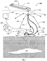
- FIG. 1 we see a schematic illustration of a system according to one embodiment of the invention for long term storage of fluids, e.g. carbon dioxide, in a subterranean void or other accommodation space 150, which typically is a subterranean aquifer.
- the subterranean void 150 may equally well be a reservoir containing gas and/or oil, a depleted gas and/or oil reservoir, a carbon dioxide storage/disposal reservoir, or a combination thereof.
- These subterranean accommodation spaces are typically located in porous or fractured rock formations, which for example may be sandstones, carbonates, or fractured shales, igneous or metamorphic rocks.
- the system includes at least one offshore injection site 100, which is configured to receive fluid, e.g. in a liquid phase, from at least one fluid tank 115 of a vessel 110.
- the offshore injection site 100 contains a subsea template 120 arranged on a seabed/sea bottom 130.
- the subsea template 120 is located at a wellhead for a drill hole 140 to the subterranean void 150.
- the subsea template 140 may also contain a utility system configured to cause the fluid from the vessel 110 to be injected into the subterranean void 150 in response to control commands C cmd .
- the utility system is not located onshore, which is advantageous for logistic reasons. For example therefore, in contrast to the above-mentioned Sn ⁇ hvit site, there is no need for any umbilicals or similar kinds of conduits to provide supplies to the utility system.
- the utility system in the subsea template 120 may contain at least one storage tank.
- the at least one storage tank holds at least one assisting liquid, which is configured to facilitate at least one function associated with injecting the fluid into the subterranean void 150.
- the at least one assisting liquid contains a de-hydrating liquid and/or an anti-freezing liquid.
- a control site is adapted to generate the control commands C cmd for controlling the flow of fluid from the vessel 110 and down into the subterranean void 150.
- the control commands C cmd may relate to opening and closure of valves when the vessel 110 connects to and disconnects from the buoy 170.
- the control site 160 is positioned at a location geographically separated from the offshore injection site 100, for example in a control room onshore. However, additionally or alternatively, the control site 160 may be positioned at an offshore location geographically separated from the offshore injection site, for example at another offshore injection site. Consequently, a single control site 160 can control multiple offshore injection sites 100. There is also large room for varying which control site 160 controls which offshore injection site 100. Communications and controls are thus located remote from the offshore injection site 100. However, as will be discussed below, the offshore injection site 100 may be powered locally, remotely or both.
- the subsea template 120 preferably contains a communication interface 120c that is communicatively connected to the control site 160.
- the subsea template 120 is also configured to receive the control commands C cmd via the communication interface 120c.
- the communication interface 120c may be configured to receive the control commands C cmd via a submerged fiber-optic and/or copper cable 165, a terrestrial radio link (not shown) and/or a satellite link (not shown). In the latter two cases, the communication interface 120c includes at least one antenna arranged above the water surface 111.
- the communicative connection between the control site 160 and the subsea template 120 is bi-directional, so that for example acknowledge messages C ack may be returned to the control site 160 from the subsea template 120.
- the offshore injection site 100 includes a buoy 170, for instance of submerged turret loading (STL) type.
- the buoy 170 When inactive, the buoy 170 may be submerged to 30 - 50 meters depth, and when the vessel 110 approaches the offshore injection site 100 to offload fluid, the buoy 170 and at least one injection riser 171 and 172 connected thereto are elevated to the water surface 111.
- this unit After that the vessel 110 has been positioned over the buoy 170, this unit is configured to be connected to the vessel 110 and receive the fluid from the vessel's fluid tank(s) 115, for example via a swivel assembly in the buoy 170.
- the buoy 170 is preferably anchored to the seabed 130 via one or more hold-back clamps 181, 182, 183 and 184, which enable the buoy 170 to elevated and lowered in the water.
- Each of the injection risers 171 and 172 respectively is configured to forward the fluid from the buoy 170 to the subsea template 120, which, in turn, is configured to pass the fluid on via the wellhead and the drill hole 140 down to the subterranean void 150.
- the subsea template 120 contains a power input interface 120p, which is configured to receive electric energy P E for operating the utility system and/or operating various functions in the buoy 170.
- the power input interface 120p may be also configured to receive the electric energy P E to be used in connection with operating a well at the wellhead, a safety barrier element of the subsea template 120 and/or a remotely operated vehicle (ROV) stationed on the seabed 130 at the subsea template 120.
- ROV remotely operated vehicle
- Figure 1 illustrates a generic power source 180, which is configured to supply the electric power P E to the power input interface 120p. It is generally advantageous if the electric power P E is supplied via a cable 185 from the power source 180 in the form of low-power direct current (DC) in the range of 200V - 1000V, preferably around 400V.
- the power source 180 may either be co-located with the offshore injection site 100, for instance as a wind turbine, a solar panel and/or a wave energy converter; and/or be positioned at an onshore site and/or at another offshore site geographically separated from the offshore injection site 100. Thus, there is a good potential for flexibility and redundancy with respect to the energy supply for the offshore injection site 100.
- the subsea template 120 contains a valve system that is configured to control the injection of the fluid into the subterranean void 150.
- the valve system may be operated by hydraulic means, electric means or a combination thereof.
- the subsea template 120 preferably also includes at least one battery configured to store electric energy for use by the valve system as a backup to the electric energy P E received directly via the power input interface 120p. More precisely, if the valve system is hydraulically operated, the subsea template 120 contains a hydraulic pressure unit (HPU) configured to supply pressurized hydraulic fluid for operation of the valve system. For example, the HPU may supply the pressurized hydraulic fluid through a hydraulic small-bore piping system.
- the at least one battery is here configured to store electric backup energy for use by the hydraulic power unit and the valve system.
- valve operations may also be operated using an electrical wiring system and electrically controlled valve actuators.
- the subsea template 120 contains an electrical wiring system configured to operate the valve system by means of electrical control signals.
- the at least one battery is configured to store electric backup energy for use by the electrical wiring system and the valve system.
- valve system may be operated also if there is a temporary outage in the electric power supply to the offshore injection site. This, in turn, increases the overall reliability of the system.
- Locating the utility system at the subsea template 120 in combination with the proposed remote control from the control site 160 avoids the need for offshore floating installations as well as permanent offshore marine installations.
- the invention allows direct injection from relatively uncomplicated maritime vessels 110. These factors render the system according to the invention very cost efficient.
- a permanent offshore installation acting as a field center for an offshore field development is bound by offshore legislation and regulations.
- DP3 dynamic positioning level 3
- the vessel 110 according to the invention does not need to provide any utilities, well or barrier control, for the injection system. Consequently, the vessel 110 may operate under maritime legislation and regulations, which are normally far less restrictive than the offshore legislation and regulations.
- FIG 2 shows a buoy 170 according to one embodiment of the invention that is configured to enable a vessel, e.g. 110 shown in Figure 1 , to connect to the fluid-transporting riser 171, which, in turn, is connected to the subsea template 120 in further fluid connection with the subterranean void 150.
- a vessel e.g. 110 shown in Figure 1
- the fluid-transporting riser 171 which, in turn, is connected to the subsea template 120 in further fluid connection with the subterranean void 150.
- a fluid injection system arranged to receive fluid, e.g. containing CO 2 , from the vessel 110.
- the fluid injection system contains the buoy 170 configured to be connected with the vessel 111 and receive the fluid therefrom.
- the system also contains the subsea template 120, which is located on the seabed 130 at the wellhead for the drill hole 140 to the subterranean void 150.
- the system includes at least one riser, here exemplified by 171 and 172 respectively, which interconnect the buoy 170 and the subsea template 120.
- Each of the at least one riser 171 and 172 is configured to transport the fluid from the buoy 170 to the subsea template 120.
- each of the at least one riser 171 and 172 is detachably connected to a bottom surface of the buoy 170 by means of a connector arrangement 210.
- Figure 5 illustrates the connector arrangement 210 according to one embodiment of the invention, which connector arrangement 210 is configured to connect the riser 171 to the buoy 170.
- any additional risers attached to the buoy 170 will be connected in an analogous manner.
- the connector arrangement 210 includes a buoy guide member 510 configured to automatically steer a connector member 570 towards the buoy guide member 510 when the connector member 570 is moved towards the buoy guide member 510.
- the connector member 570 is attached in a head end 300 of the riser 171 to be connected to the buoy 170.
- the connector arrangement 210 further includes a mating member 550, for example embodied as so-called fingers, configured to attach a first sealing surface S70 of the connector member 570 to a second sealing surface S10 of the buoy guide member 510 when said head end 300 has been moved such that the connector member 570 contacts the buoy guide member 510.
- the connector arrangement 210 includes a locking member 560 configured to lock the first and second sealing surfaces S70 and S10 to one another when these surfaces are aligned with one another.
- the connector arrangement 210 contains one collet connector for each riser to be connected to the buoy 170.
- the collet connector typically also includes a seal gasket 530, which is arranged between the first and second sealing surfaces S70 and S10 to further reduce the risk of leakages.
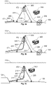
- Figures 3a, 3b and 3c illustrate how a riser 171 is connected to a buoy 170 according to one embodiment of the invention.
- the head end 300 of the riser 171 to be connected contains a plug member 317 covering the first sealing surface S70.
- the head end 300 of the riser 171 to be connected preferably includes a drag-eye member 305, which facilitates connecting a winch wire to the head end 300 and pulling the riser 171 up to the buoy 170 as described below.
- the plug member 317 is configured to encircle the riser 171 to be connected to the buoy 170. After that the plug member 317 has been disconnected from the head end 300 of the riser 171, the plug member 317 is further configured to be transported by gravity G down along said riser 171 towards the subsea template 120.
- the fluid injection system contains a winch unit 330, which is arranged on the seabed 130.
- the winch unit 330 is configured to pull up the head end 300 of the riser 171 to be connected to the buoy 170 via a winch wire 320 connected between the head end 300 of the riser 171 and the winch unit 330.
- the which wire 320 runs via the buoy 170 to the winch unit 330.
- the winch wire 320 is led through the buoy 170 and via at least one sheave wheel 325 on the buoy 170 as illustrated in Figures 3a and 3b .
- the fluid injection system includes an ROV 350 that is configured to be remote controlled to attach the winch wire 320 to the head end 300 of the riser 171. Further preferably, the ROV 350 is configured to disconnect the plug member 317 from the first sealing surface S70 of the connector member 570 in the head end 300 of the riser 171; and thereafter, connect the riser 171 to the buoy 170.
- a first step 610 the ROV 350 is controlled to attach the winch wire 320 to the head end 300 of the riser 171.
- a step 620 the ROV 350 is controlled to lead the winch wire 320 via the buoy 170 to the winch unit 330 on the seabed 130 below the buoy 170.
- the winch unit 330 is controlled to pull up the head end 300 of the riser (171) to a bottom side of the buoy 170.
- a step 640 thereafter, the ROV 350 is controlled to connect the head end 300 of the riser 171 to the connector arrangement 210 in the bottom of the buoy 170.
- FIG. 4 schematically illustrates an interior of a subsea template 220 according to one embodiment of the invention.
- an exemplary riser 171 is shown, which has a base section 410 and an upright section 420.
- the upright section 420 constitutes an uppermost part, which is further connected to the buoy 170.
- the base section 410 constitutes a lowermost part of the riser 171, which, in a receiving end 411, is connected to the upright section 420; and in an emitting end 412, is connected to the subsea template 120.
- each of the risers 171 and 172 contains a holdback clamp 17C, which is configured to hold the base section 410 of the riser in a desired position via a restraining riser 17R attached to the seabed 130.
- the subsea template 120 contains an injection valve tree 460, which is in fluid connection with the wellhead 470 for the drill hole 140.
- the subsea template 120 also contains a sleeve member 440 having penetration means 441, e.g. represented by a pipe-piece extending substantially orthogonally relative to an extension of the sleeve member 440, which penetration means 441 is configured to penetrate the riser 171 in the emitting end 412 of the base section 410.
- penetration means 441 will create an opening in the riser 171. This opening, in turn, is connectable to the injection valve tree 460.
- a vertical connector extending from the penetration means 441 has a relatively large tolerance for deviation, say allowing up to 5-10 degrees misalignment. Namely, this allows for a useful flexibility when installing the riser 171 in the subsea template 120. Tolerance budgets are estimated based upon accuracy of fabrication, assembly and installation, and flexibility in the piping and misalignment acceptance in the connectors used.
- the sleeve member 440 contains, or is associated with, at least one guide member, which is exemplified by 432 in Figure 4 .
- the guide member 440 is shaped and arranged relative to the penetration means 441 so as to steer the emitting end 412 of the base section 410 towards the penetration means 441 to allow the emitting end 412 of the base section 410 to land down at a certain speed and provide a finer and finer alignment with the penetration means 441.
- the guide member 432 may have a general funnel shape converging towards the penetration means 441.
- the guide member 432 is configured to steer the emitting end 412 of the base section 410 towards the sleeve member when the emitting end 412 of the base section 410 is brought towards the subsea template 120.
- a first step 710 the ROV 350 is controlled to steer the emitting end 412 of the base section 410 of the riser 171 to the template guide member 432 on the subsea template 120.
- the ROV 350 is controlled to feed the emitting end 412 of the base section 410 of the riser 171 via the template guide member 432 to the sleeve member 440, which has penetration means 441 configured to penetrate the riser 171. Consequently, when the second end 412 of the base section 410 is fed into the sleeve member 440, the penetration means 441 is caused to penetrate the riser 171 in the second end 412 and create an opening in the riser 171.
- the ROV 350 is controlled to connect the sleeve member 440 to the injection valve tree 460 in the subsea template 120.
- the subsea template 120 contains a jumper pipe 450 having a general U-shape, which is configured to establish a fluid connection between the opening in the riser 171 and the injection valve tree 460.
- a jumper pipe 450 having a general U-shape, which is configured to establish a fluid connection between the opening in the riser 171 and the injection valve tree 460.
- the jumper pipe 450 may also act as a "injection choke bridge.”
- the jumper pipe 450 includes a choke valve and instrumentation for controlling the injection of the fluid.
- the jumper pipe 450 is designed with such design tolerances that it is attachable both onto the vertical connector extending from the penetration means 441 and the valve tree 460.
- this connection also includes a valve 445, e.g. of ball or gate type, such that a rate of the fluid flow into the injection valve tree 460 can be regulated, and shut off if needed. It is advantageous if the valve 445 is configured to be operable by the ROV 350.
- the subsea template 120 contains at least one heating unit.
- a generic heating unit 480 is illustrated, which is configured to heat the fluid received from the riser 171 before the fluid is being injected into the subterranean void 150.
- obstructing fluid plugs can be removed from the base section 410 of the riser 171 in a straightforward manner.
- the base section 410 extends between the receiving end 411 and the emitting end 412 of the riser 171, where the receiving end 411 is connected to the upright section 420 of the riser 171 and the emitting end 412 of the riser 171 is connected to the subsea template 120.
- the subsea template 120 is further connected to the wellhead (470) for a drill hole 140 to the subterranean void 150 into which fluid received via the riser 171 is to be injected from the subsea template 120.
- a first step 910 the heating unit 480 is controlled to heat at least one portion of the base section 410.
- a subsequent step 920 checks if the least one portion of the base section 410 has reached a predetermined temperature. If so, a step 930 follows; and otherwise, the procedure loops back to step 910.
- step 930 the heating unit 480 is controlled to maintain a temperature level above or equal to the predetermined temperature in the at least one section of the base section.
- a step checks if a heating period has expired. If so, the procedure ends; and otherwise, the procedure loops back to step 930.
- the subsea template 120 contains a power interface 120p that is configured to receive electric power P E via an electric power line 185 on the seabed 130, for example from an onshore power source 180. It is also advantageous if the subsea template 120 contains at least one battery 490 configured to provide electric power to at least one unit in the subsea template 120, for instance the heating unit 480, the valve 445 and/ or the injection valve tree 460.
- the at least one battery 490 is configured to be charged by electric power P E received via the power interface 120p.
- the ROV 350 is preferably configured to be controlled to effect at least one procedure in connection with controlling the valve 445 in the subsea template 120, controlling one or more valves in the buoy 170 and/or performing maintenance of the fluid injection system.
- Figure 8 illustrates, by means of a flow diagram, a method for removing obstructing fluid plugs in the riser 171, which is an alternative to the method described above with reference to Figure 9 .
- a first step 810 at least one assisting liquid is heated to a predetermined temperature in the vessel 110.
- a step 820 at least one container holding the at least one heated assisting liquid is/are forwarded from the vessel 110 to a storage container in the subsea template 120.
- the at least one heated assisting liquid is/are injected from the storage container into at least one injection point in the base section 410 of the riser 171, and from the vessel 110 into at least one injection point in the upright section 420 of the riser 171.
- step 840 it is checked if the plugs in the riser 171 have melted away. If so, the procedure ends; and otherwise, the procedure loops back to step 810.
Landscapes
- Engineering & Computer Science (AREA)
- Life Sciences & Earth Sciences (AREA)
- Geology (AREA)
- Mining & Mineral Resources (AREA)
- Environmental & Geological Engineering (AREA)
- Fluid Mechanics (AREA)
- General Life Sciences & Earth Sciences (AREA)
- Geochemistry & Mineralogy (AREA)
- Physics & Mathematics (AREA)
- Mechanical Engineering (AREA)
- Chemical & Material Sciences (AREA)
- Combustion & Propulsion (AREA)
- Ocean & Marine Engineering (AREA)
- Marine Sciences & Fisheries (AREA)
- Architecture (AREA)
- Civil Engineering (AREA)
- Structural Engineering (AREA)
- Chemical Kinetics & Catalysis (AREA)
- Earth Drilling (AREA)
- Turbine Rotor Nozzle Sealing (AREA)
Priority Applications (9)
| Application Number | Priority Date | Filing Date | Title |
|---|---|---|---|
| EP21165680.6A EP4067616A1 (fr) | 2021-03-29 | 2021-03-29 | Système d'injection de carburant et procédés associés |
| PCT/EP2022/058314 WO2022207661A1 (fr) | 2021-03-29 | 2022-03-29 | Système d'injection de fluide |
| CA3212240A CA3212240A1 (fr) | 2021-03-29 | 2022-03-29 | Systeme d'injection de fluide et procedes associes |
| PCT/EP2022/058326 WO2022207666A1 (fr) | 2021-03-29 | 2022-03-29 | Système d'injection de fluide et procédés associés |
| US18/284,428 US20240159117A1 (en) | 2021-03-29 | 2022-03-29 | Fluid injection system and related methods |
| CA3212443A CA3212443A1 (fr) | 2021-03-29 | 2022-03-29 | Procedes d'installation de colonnes montantes dans un systeme d'injection de fluide |
| PCT/EP2022/058328 WO2022207668A1 (fr) | 2021-03-29 | 2022-03-29 | Procédés d'installation de colonnes montantes dans un système d'injection de fluide |
| EP22719823.1A EP4298311B1 (fr) | 2021-03-29 | 2022-03-29 | Système d'injection de carburant et procédés associés |
| EP22718972.7A EP4298310A1 (fr) | 2021-03-29 | 2022-03-29 | Procédés d'installation de colonnes montantes dans un système d'injection de fluide |
Applications Claiming Priority (1)
| Application Number | Priority Date | Filing Date | Title |
|---|---|---|---|
| EP21165680.6A EP4067616A1 (fr) | 2021-03-29 | 2021-03-29 | Système d'injection de carburant et procédés associés |
Publications (1)
| Publication Number | Publication Date |
|---|---|
| EP4067616A1 true EP4067616A1 (fr) | 2022-10-05 |
Family
ID=75277910
Family Applications (3)
| Application Number | Title | Priority Date | Filing Date |
|---|---|---|---|
| EP21165680.6A Withdrawn EP4067616A1 (fr) | 2021-03-29 | 2021-03-29 | Système d'injection de carburant et procédés associés |
| EP22719823.1A Active EP4298311B1 (fr) | 2021-03-29 | 2022-03-29 | Système d'injection de carburant et procédés associés |
| EP22718972.7A Pending EP4298310A1 (fr) | 2021-03-29 | 2022-03-29 | Procédés d'installation de colonnes montantes dans un système d'injection de fluide |
Family Applications After (2)
| Application Number | Title | Priority Date | Filing Date |
|---|---|---|---|
| EP22719823.1A Active EP4298311B1 (fr) | 2021-03-29 | 2022-03-29 | Système d'injection de carburant et procédés associés |
| EP22718972.7A Pending EP4298310A1 (fr) | 2021-03-29 | 2022-03-29 | Procédés d'installation de colonnes montantes dans un système d'injection de fluide |
Country Status (4)
| Country | Link |
|---|---|
| US (1) | US20240159117A1 (fr) |
| EP (3) | EP4067616A1 (fr) |
| CA (2) | CA3212240A1 (fr) |
| WO (3) | WO2022207661A1 (fr) |
Cited By (1)
| Publication number | Priority date | Publication date | Assignee | Title |
|---|---|---|---|---|
| GB2624646A (en) * | 2022-11-23 | 2024-05-29 | Baker Hughes Energy Technology UK Ltd | System for use in carbon storage |
Citations (9)
| Publication number | Priority date | Publication date | Assignee | Title |
|---|---|---|---|---|
| GB2090222A (en) * | 1980-12-29 | 1982-07-07 | Mobil Oil Corp | Marine compliant riser system and method for its installation |
| WO1993024733A1 (fr) * | 1992-05-25 | 1993-12-09 | Den Norske Stats Oljeselskap A.S. | Systeme utilise pour la production de petrole sous-marin |
| US20060140726A1 (en) * | 2002-10-16 | 2006-06-29 | Jack Pollack | Riser installation vessel and method of using the same |
| US20080135258A1 (en) * | 2006-12-06 | 2008-06-12 | Chevron U.S.A. Inc. | Method for Preventing Overpressure |
| US20110017465A1 (en) | 2008-04-09 | 2011-01-27 | AMOG Pty Ltd. | Riser support |
| US20140318791A1 (en) * | 2013-04-29 | 2014-10-30 | Oceaneering International, Inc. | System and method for subsea structure obstruction remediation using an exothermic chemical reaction |
| US9631438B2 (en) | 2011-05-19 | 2017-04-25 | Subsea Technologies Group Limited | Connector |
| US9784044B2 (en) | 2014-08-11 | 2017-10-10 | IFP Energies Nouvelles | Connector for risers equipped with an external locking collar |
| US20190162336A1 (en) * | 2016-07-25 | 2019-05-30 | National Oilwell Varco Denmark I/S | Detecting parameter in flexible pipe system comprising a turret |
Family Cites Families (13)
| Publication number | Priority date | Publication date | Assignee | Title |
|---|---|---|---|---|
| BR0109766A (pt) * | 2000-03-27 | 2003-02-04 | Rockwater Ltd | Tubo ascendente com serviços internos recuperáveis |
| GB0216259D0 (en) * | 2002-07-12 | 2002-08-21 | Sensor Highway Ltd | Subsea and landing string distributed sensor system |
| GB2456300B (en) * | 2008-01-08 | 2010-05-26 | Schlumberger Holdings | Monitoring system for pipelines or risers in floating production installations |
| US20100051279A1 (en) * | 2008-09-02 | 2010-03-04 | Baugh Paula B | Method of prevention of hydrates |
| US8960302B2 (en) * | 2010-10-12 | 2015-02-24 | Bp Corporation North America, Inc. | Marine subsea free-standing riser systems and methods |
| US20120273213A1 (en) * | 2011-04-27 | 2012-11-01 | Bp Corporation North America Inc. | Marine subsea riser systems and methods |
| GB2509165B (en) * | 2012-12-21 | 2018-01-24 | Subsea 7 Norway As | Subsea processing of well fluids |
| GB2525609B (en) * | 2014-04-28 | 2017-04-19 | Acergy France SAS | Riser system with gas-lift facility |
| WO2016057126A1 (fr) * | 2014-10-10 | 2016-04-14 | Exxonmobil Upstream Research Company | Utilisation de pompe à bulles pour déchargement de liquide de conduite d'écoulement verticale |
| NO20160763A1 (en) * | 2016-05-06 | 2017-11-07 | Wellguard As | A wellbore system, tool and method |
| GB2590616A (en) * | 2019-12-20 | 2021-07-07 | Aker Solutions As | Heating systems |
| BR102019028092A2 (pt) * | 2019-12-27 | 2021-07-06 | Petróleo Brasileiro S.A. - Petrobras | sistema de combate e remoção de hidratos e outros bloqueios em dutos submarinos |
| EP4127394B1 (fr) * | 2020-03-24 | 2024-03-13 | TotalEnergies OneTech | Appareil de chauffage sous-marin pour chauffer un composant sous-marin, tel qu'un pipeline sous-marin, ensemble de chauffage sous-marin associé, système de chauffage sous-marin, installation de production de pétrole et de gaz et procédé de fabrication |
-
2021
- 2021-03-29 EP EP21165680.6A patent/EP4067616A1/fr not_active Withdrawn
-
2022
- 2022-03-29 WO PCT/EP2022/058314 patent/WO2022207661A1/fr active Application Filing
- 2022-03-29 WO PCT/EP2022/058326 patent/WO2022207666A1/fr active Application Filing
- 2022-03-29 CA CA3212240A patent/CA3212240A1/fr active Pending
- 2022-03-29 WO PCT/EP2022/058328 patent/WO2022207668A1/fr active Application Filing
- 2022-03-29 EP EP22719823.1A patent/EP4298311B1/fr active Active
- 2022-03-29 CA CA3212443A patent/CA3212443A1/fr active Pending
- 2022-03-29 EP EP22718972.7A patent/EP4298310A1/fr active Pending
- 2022-03-29 US US18/284,428 patent/US20240159117A1/en active Pending
Patent Citations (9)
| Publication number | Priority date | Publication date | Assignee | Title |
|---|---|---|---|---|
| GB2090222A (en) * | 1980-12-29 | 1982-07-07 | Mobil Oil Corp | Marine compliant riser system and method for its installation |
| WO1993024733A1 (fr) * | 1992-05-25 | 1993-12-09 | Den Norske Stats Oljeselskap A.S. | Systeme utilise pour la production de petrole sous-marin |
| US20060140726A1 (en) * | 2002-10-16 | 2006-06-29 | Jack Pollack | Riser installation vessel and method of using the same |
| US20080135258A1 (en) * | 2006-12-06 | 2008-06-12 | Chevron U.S.A. Inc. | Method for Preventing Overpressure |
| US20110017465A1 (en) | 2008-04-09 | 2011-01-27 | AMOG Pty Ltd. | Riser support |
| US9631438B2 (en) | 2011-05-19 | 2017-04-25 | Subsea Technologies Group Limited | Connector |
| US20140318791A1 (en) * | 2013-04-29 | 2014-10-30 | Oceaneering International, Inc. | System and method for subsea structure obstruction remediation using an exothermic chemical reaction |
| US9784044B2 (en) | 2014-08-11 | 2017-10-10 | IFP Energies Nouvelles | Connector for risers equipped with an external locking collar |
| US20190162336A1 (en) * | 2016-07-25 | 2019-05-30 | National Oilwell Varco Denmark I/S | Detecting parameter in flexible pipe system comprising a turret |
Non-Patent Citations (3)
| Title |
|---|
| EIKEN, O. ET AL.: "Lessons Learned from 14 years of CCS Operations: Sleipner, In Salah and Snohvit", ENERGY PROCEDIA, vol. 4, 2011, pages 5541 - 5548, XP028213594, DOI: 10.1016/j.egypro.2011.02.541 |
| HAUGEN, H. A. ET AL.: "13th International Conference on Greenhouse Gas Control Technologies, GHGT-13, 14-18 - November 2016, Lausanne, Switzerland Commercial capture and transport of C02 from production of ammonia", ENERGY PROCEDIA, vol. 114, 2017, pages 6133 - 6140 |
| SHI, J-Q ET AL.: "Snohvit C0 storage project: Assessment of C0 injection performance through history matching of the injection well pressure over a 32-months period", ENERGY PROCEDIA, vol. 37, 2013, pages 3267 - 3274 |
Cited By (1)
| Publication number | Priority date | Publication date | Assignee | Title |
|---|---|---|---|---|
| GB2624646A (en) * | 2022-11-23 | 2024-05-29 | Baker Hughes Energy Technology UK Ltd | System for use in carbon storage |
Also Published As
| Publication number | Publication date |
|---|---|
| CA3212240A1 (fr) | 2022-10-06 |
| EP4298310A1 (fr) | 2024-01-03 |
| WO2022207666A1 (fr) | 2022-10-06 |
| WO2022207668A1 (fr) | 2022-10-06 |
| EP4298311B1 (fr) | 2024-10-23 |
| EP4298311A1 (fr) | 2024-01-03 |
| US20240159117A1 (en) | 2024-05-16 |
| CA3212443A1 (fr) | 2022-10-06 |
| WO2022207661A1 (fr) | 2022-10-06 |
Similar Documents
| Publication | Publication Date | Title |
|---|---|---|
| US6752214B2 (en) | Extended reach tie-back system | |
| EP4240937B1 (fr) | Système et procédé de manipulation de fluides sous-marins pour le stockage à long terme de fluides dans un vide sous-marin | |
| CN102561979A (zh) | 用于从rov向立管中工具输送感应信号和功率的系统和方法 | |
| WO2007028982A1 (fr) | Ensemble cadre sous-marin d’extrémité de conduite de transport & de guide de forage | |
| CN101568757B (zh) | 具有不同的管接头的近海管柱 | |
| EP4298311B1 (fr) | Système d'injection de carburant et procédés associés | |
| WO2010144187A1 (fr) | Systèmes et procédés de récupération d'hydrocarbures sous-marins | |
| US20240068332A1 (en) | Buoy for injecting fluid in a subterranean void and methods for connecting and disconnecting a fluid passage from a vessel to the buoy | |
| US6012530A (en) | Method and apparatus for producing and shipping hydrocarbons offshore | |
| CA3210348A1 (fr) | Gabarit sous-marin pour injecter un fluide pour un stockage a long terme dans un vide souterrain et procede de commande d'un gabarit sous-marin | |
| NO347106B1 (en) | Buoy for Injecting Fluid in a Subterranean Void and Methods for Connecting and Disconnecting a Fluid Passage from a Vessel to the Buoy | |
| NO346594B1 (en) | Subsea Template for Injecting Fluid for Long Term Storage in a Subterranean Void and Method of Controlling a Subsea Template | |
| Henry et al. | Innovations in subsea development and operation | |
| Taulois | Kvaerner Deepwater Solutions | |
| Pelleau et al. | Design, Installation, And Connection Of Subsea Lines On East Frigg Field | |
| Childers et al. | Test Of A Submerged Production System-Progress Report | |
| e Silva | Roncador Field: The Operational Experience on 1-RJS-436 A: The Pilot Well | |
| Ames et al. | Troika" Plan B: Implementation of a Temporary Hydraulic/Methanol Supply System From a Deepwater MODU | |
| Alekseev et al. | Submudline Production Systems As a Solution to Iceberg Hazards |
Legal Events
| Date | Code | Title | Description |
|---|---|---|---|
| PUAI | Public reference made under article 153(3) epc to a published international application that has entered the european phase |
Free format text: ORIGINAL CODE: 0009012 |
|
| STAA | Information on the status of an ep patent application or granted ep patent |
Free format text: STATUS: THE APPLICATION HAS BEEN PUBLISHED |
|
| AK | Designated contracting states |
Kind code of ref document: A1 Designated state(s): AL AT BE BG CH CY CZ DE DK EE ES FI FR GB GR HR HU IE IS IT LI LT LU LV MC MK MT NL NO PL PT RO RS SE SI SK SM TR |
|
| STAA | Information on the status of an ep patent application or granted ep patent |
Free format text: STATUS: REQUEST FOR EXAMINATION WAS MADE |
|
| 17P | Request for examination filed |
Effective date: 20221221 |
|
| RBV | Designated contracting states (corrected) |
Designated state(s): AL AT BE BG CH CY CZ DE DK EE ES FI FR GB GR HR HU IE IS IT LI LT LU LV MC MK MT NL NO PL PT RO RS SE SI SK SM TR |
|
| REG | Reference to a national code |
Ref country code: NO Ref legal event code: TC |
|
| STAA | Information on the status of an ep patent application or granted ep patent |
Free format text: STATUS: EXAMINATION IS IN PROGRESS |
|
| 17Q | First examination report despatched |
Effective date: 20230825 |
|
| STAA | Information on the status of an ep patent application or granted ep patent |
Free format text: STATUS: THE APPLICATION IS DEEMED TO BE WITHDRAWN |
|
| 18D | Application deemed to be withdrawn |
Effective date: 20240105 |