EP4067608B1 - Mechatronischer schlüssel - Google Patents
Mechatronischer schlüssel Download PDFInfo
- Publication number
- EP4067608B1 EP4067608B1 EP22161696.4A EP22161696A EP4067608B1 EP 4067608 B1 EP4067608 B1 EP 4067608B1 EP 22161696 A EP22161696 A EP 22161696A EP 4067608 B1 EP4067608 B1 EP 4067608B1
- Authority
- EP
- European Patent Office
- Prior art keywords
- key
- ring
- electric circuit
- cover
- longitudinal axis
- Prior art date
- Legal status (The legal status is an assumption and is not a legal conclusion. Google has not performed a legal analysis and makes no representation as to the accuracy of the status listed.)
- Active
Links
Images


Classifications
-
- E—FIXED CONSTRUCTIONS
- E05—LOCKS; KEYS; WINDOW OR DOOR FITTINGS; SAFES
- E05B—LOCKS; ACCESSORIES THEREFOR; HANDCUFFS
- E05B19/00—Keys; Accessories therefor
- E05B19/04—Construction of the bow or head of the key; Attaching the bow to the shank
-
- E—FIXED CONSTRUCTIONS
- E05—LOCKS; KEYS; WINDOW OR DOOR FITTINGS; SAFES
- E05B—LOCKS; ACCESSORIES THEREFOR; HANDCUFFS
- E05B35/00—Locks for use with special keys or a plurality of keys ; keys therefor
- E05B35/14—Locks for use with special keys or a plurality of keys ; keys therefor with keys of which different parts operate separate mechanisms
-
- G—PHYSICS
- G06—COMPUTING OR CALCULATING; COUNTING
- G06K—GRAPHICAL DATA READING; PRESENTATION OF DATA; RECORD CARRIERS; HANDLING RECORD CARRIERS
- G06K19/00—Record carriers for use with machines and with at least a part designed to carry digital markings
- G06K19/06—Record carriers for use with machines and with at least a part designed to carry digital markings characterised by the kind of the digital marking, e.g. shape, nature, code
- G06K19/067—Record carriers with conductive marks, printed circuits or semiconductor circuit elements, e.g. credit or identity cards also with resonating or responding marks without active components
- G06K19/07—Record carriers with conductive marks, printed circuits or semiconductor circuit elements, e.g. credit or identity cards also with resonating or responding marks without active components with integrated circuit chips
- G06K19/077—Constructional details, e.g. mounting of circuits in the carrier
- G06K19/07749—Constructional details, e.g. mounting of circuits in the carrier the record carrier being capable of non-contact communication, e.g. constructional details of the antenna of a non-contact smart card
-
- G—PHYSICS
- G07—CHECKING-DEVICES
- G07C—TIME OR ATTENDANCE REGISTERS; REGISTERING OR INDICATING THE WORKING OF MACHINES; GENERATING RANDOM NUMBERS; VOTING OR LOTTERY APPARATUS; ARRANGEMENTS, SYSTEMS OR APPARATUS FOR CHECKING NOT PROVIDED FOR ELSEWHERE
- G07C9/00—Individual registration on entry or exit
- G07C9/00174—Electronically operated locks; Circuits therefor; Nonmechanical keys therefor, e.g. passive or active electrical keys or other data carriers without mechanical keys
- G07C9/00309—Electronically operated locks; Circuits therefor; Nonmechanical keys therefor, e.g. passive or active electrical keys or other data carriers without mechanical keys operated with bidirectional data transmission between data carrier and locks
-
- G—PHYSICS
- G07—CHECKING-DEVICES
- G07C—TIME OR ATTENDANCE REGISTERS; REGISTERING OR INDICATING THE WORKING OF MACHINES; GENERATING RANDOM NUMBERS; VOTING OR LOTTERY APPARATUS; ARRANGEMENTS, SYSTEMS OR APPARATUS FOR CHECKING NOT PROVIDED FOR ELSEWHERE
- G07C9/00—Individual registration on entry or exit
- G07C9/00174—Electronically operated locks; Circuits therefor; Nonmechanical keys therefor, e.g. passive or active electrical keys or other data carriers without mechanical keys
- G07C9/00944—Details of construction or manufacture
-
- E—FIXED CONSTRUCTIONS
- E05—LOCKS; KEYS; WINDOW OR DOOR FITTINGS; SAFES
- E05B—LOCKS; ACCESSORIES THEREFOR; HANDCUFFS
- E05B47/00—Operating or controlling locks or other fastening devices by electric or magnetic means
- E05B2047/0094—Mechanical aspects of remotely controlled locks
-
- E—FIXED CONSTRUCTIONS
- E05—LOCKS; KEYS; WINDOW OR DOOR FITTINGS; SAFES
- E05B—LOCKS; ACCESSORIES THEREFOR; HANDCUFFS
- E05B35/00—Locks for use with special keys or a plurality of keys ; keys therefor
- E05B35/003—Locks for use with special keys or a plurality of keys ; keys therefor for keys with movable bits
-
- E—FIXED CONSTRUCTIONS
- E05—LOCKS; KEYS; WINDOW OR DOOR FITTINGS; SAFES
- E05B—LOCKS; ACCESSORIES THEREFOR; HANDCUFFS
- E05B47/00—Operating or controlling locks or other fastening devices by electric or magnetic means
- E05B47/06—Controlling mechanically-operated bolts by electro-magnetically-operated detents
- E05B47/0611—Cylinder locks with electromagnetic control
- E05B47/0615—Cylinder locks with electromagnetic control operated by handles, e.g. by knobs
-
- E—FIXED CONSTRUCTIONS
- E05—LOCKS; KEYS; WINDOW OR DOOR FITTINGS; SAFES
- E05B—LOCKS; ACCESSORIES THEREFOR; HANDCUFFS
- E05B47/00—Operating or controlling locks or other fastening devices by electric or magnetic means
- E05B47/06—Controlling mechanically-operated bolts by electro-magnetically-operated detents
- E05B47/0676—Controlling mechanically-operated bolts by electro-magnetically-operated detents by disconnecting the handle
-
- E—FIXED CONSTRUCTIONS
- E05—LOCKS; KEYS; WINDOW OR DOOR FITTINGS; SAFES
- E05B—LOCKS; ACCESSORIES THEREFOR; HANDCUFFS
- E05B49/00—Electric permutation locks; Circuits therefor ; Mechanical aspects of electronic locks; Mechanical keys therefor
-
- G—PHYSICS
- G07—CHECKING-DEVICES
- G07C—TIME OR ATTENDANCE REGISTERS; REGISTERING OR INDICATING THE WORKING OF MACHINES; GENERATING RANDOM NUMBERS; VOTING OR LOTTERY APPARATUS; ARRANGEMENTS, SYSTEMS OR APPARATUS FOR CHECKING NOT PROVIDED FOR ELSEWHERE
- G07C9/00—Individual registration on entry or exit
- G07C9/00174—Electronically operated locks; Circuits therefor; Nonmechanical keys therefor, e.g. passive or active electrical keys or other data carriers without mechanical keys
- G07C9/00944—Details of construction or manufacture
- G07C2009/00952—Electronic keys comprising a mechanical key within their housing, e.g. extractable or retractable emergency key
Definitions
- the present invention relates to a mechatronic key, i.e. a mechanical electrical key. More specifically, the proposed key comprises a radiocommunication circuit that is configured to wirelessly communicate with a control circuit of an access system.
- RFID radio frequency identification
- An RFID system uses electromagnetic fields to automatically identify and/or track tags attached to objects, such as keys.
- An RFID system generally consists of a small radio transponder, and a reader device comprising a radio receiver and transmitter. When triggered by an electromagnetic interrogation pulse from a nearby RFID reader device, the tag transmits digital data back to the reader. The received data can then be used by the reader device to identify the tag.
- Passive tags are powered by energy from the reader device's interrogating radio waves. Active tags on the other hand are powered by a battery and thus can be generally read at a greater range from the reader device, up to hundreds of meters.
- DE102015205213A1 relates to a profile cylinder key with a key head and with a key shank extending from the key head.
- the key head has a material recess, and an RFID transponder unit being arranged therein.
- US6308542B1 discloses key assemblies each having a key blank, a transponder, a transponder holder, and a key head section cover moulded to encapsulate the transponder and at least part of its holder.
- the proposed new key has the advantage that the key, and in particular the key head, can be made much thinner compared to existing mechatronic keys. More specifically, the thickness of the key head can be only minimally thicker than the thickness of the key blade. Moreover, the proposed key is reversible. This means that either side of the key head may be pointed at a reader device and the data from the electric or radiocommunication circuit, such as an RFID circuit, can still be successfully read by the reader device. Furthermore, the manufacturing process of the key can be simplified compared to a manufacturing process of existing mechatronic keys. This in turn leads to reduced manufacturing costs. It is further to be noted that the design of the proposed mechatronic key can be made relatively similar to existing mechanical keys. This aspect would keep the manufacturing costs to the minimum for the entire key portfolio.
- a lock system comprising the key according to the first aspect of the invention, and further comprising a reader device configured to wirelessly read a coding of the electric circuit when the key is placed within a wireless reading distance from the reader device.
- proximal end is understood in the present description to mean the end or side which is closer to the user of the key.
- distal end is understood to be the opposite end, in other words the end away from the user of the key.
- Identical or corresponding functional and structural elements which appear in the different drawings are assigned the same reference numerals.
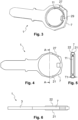
- the key 1, which in this case is a mechatronic key, as shown in the drawings can be understood to be divided into a key blade 3, also known as a key shank or key shaft, and key head 5 for gripping the key.
- a mechatronic key may in the present description be understood an electronic or smart key having a key blade which may or may not have a mechanical key coding.
- the key blade is sized and shaped to be received in a key channel, which is also known as a key slot, keyhole or keyway of a key lock, such as a cylinder lock.
- the key blade may comprise a mechanical key coding scheme or system, which however is not shown in the drawings for simplicity.
- the key blade also defines a longitudinal axis A1 of the key. This axis substantially coincides with the longitudinal axis of the key channel when the key is in the key channel. By moving the key along this axis, the key can be inserted into the key channel.
- the key blade 3 has a substantially rectangular cross-section, but other cross-sectional shapes, such as a substantially circular shape, are also possible.
- the key blade may comprise pin-engaging means, generally referred to as dimples, on the top and/or bottom edge and/or on one or both lateral sides of the blade, which are arranged to engage with rotor pins when the key blade is inserted into a key channel of a lock.
- the lateral side(s) of the blade may additionally or instead comprise one or more grooves to engage with further validating means, known as tumblers in a rotor of a key cylinder.
- the teachings of the invention would also apply to keys with no grooves, or one or more grooves possibly on either lateral side of the key blade.
- the lateral side(s) could comprise further dimples, cavities and/or protrusions.
- the key blade may also optionally comprise on at least one of its lateral sides an electronic structural element (not shown in the figures). The purpose of this element would be to create a physical contact with electrical contacts in the key lock. In this manner, this optional electronic element may also be used to unlock the lock.
- the key blade may as well comprise at least on one of the top and bottom edges and/or or on at least one of the lateral sides a dynamical part (not shown in the figures), which may be understood as a force transferring element or means.
- the force transferring element may be configured as a pivoting element.
- the force transferring means may also be called an active moving element, since it may be arranged to be actively urged by at least one rotor pin.
- the pivoting element may at least be partly made of metal, plastic or ceramic, or a combination thereof.
- the pivoting element may be provided in a cavity in the key blade 3.
- the pivoting element may be held in place by holding means, such as a rivet, and it may be arranged to rotate or pivot about a rotation axis, which would coincide with the longitudinal axis of the rivet.
- the holding means may or may not pass through the whole lateral cross section of the key.
- the rotation axis is not fixed, but may be arranged to move so that the rotation axis remains substantially orthogonal to the longitudinal axis of the key.
- One of the advantages of the pivoting element would be that key blanks, keys and/or the cylinder locks would be more difficult to reproduce by unauthorised third parties. Furthermore, this kind of key would provide increased security, because the pivoting element can be used to code the key. Furthermore, fraudulent opening of the lock is made more difficult, because at least one of the rotor pins may have to be in a recessed position in its through hole in order to rotate the rotor.
- the key head 5 comprises a ring 7 encompassing or surrounding a cavity 9, which in this case is a central cavity of the key head.
- the ring may thus be understood to form an unbroken or broken loop or band, but not necessarily a loop of a circular shape, i.e. the ring may be of a circular shape or of a non-circular shape.
- the ring and the key blade form a monobloc element, i.e. they form one single piece or element.
- the key blade is thus arranged at a distal end of the key, while the ring is at a proximal end of the key.
- the key blade extends between the ring at a central or middle region of the key and a tip of the key forming the distal end of the key.
- the key also comprises an electric circuit 11, such as an RFID tag, which is arranged to wirelessly communicate with an electronic control device 13 of a locking system, referred to also as a lock, and which in this case may also comprise the cylinder lock.
- the electric circuit is partially or fully placed in the cavity 9.
- the electric circuit is an RFID tag 11, and more specifically a passive RFID tag, while the electronic control device is an RFID reader device.
- the RFID tag 11 is thus configured to communicate with the RFID reader device 13, which may be comprised in the cylinder lock system or be a part of the cylinder lock system as an outstanding member. In this manner the RFID tag 11, and the RFID reader device 13 comprise the key coding.
- the RFID reader device In order to be able to unlock the locking system, the RFID reader device has to be able to read the correct coding from the RFID tag. In response to having read the correct coding, the RFID reader device will change the state of the locking system to an unlocked state, or when the key coding is not recognised, the locking system remains in a locked state. As the communication between the RFID tag 11 and the RFID reader device 13 takes place by radio transmission, this means that depending on how the lock system is configured, the key 1 does not necessarily have to be inserted into the key channel in order to change the state of the locking system. However, optionally, in order to unlock the locking system, and in particular the cylinder lock, it is also necessary to insert the key into the key channel in order to also unlock the mechanical locking mechanism of the cylinder lock.
- both the mechanical coding and the coding of the RFID tag may have to be read in order to fully unlock the locking system.
- the above-mentioned electronic structural element may also optionally be used to lock and/or unlock the locking system.
- the RFID tag may also optionally be used to lock the locking system, if it is configured in this manner.
- the locking system may also be configured so that it automatically changes its sate to the locked state after a given time period has passed since the last successful reading of the coding of the RFID tag. Also, the locking system may be configured so that the state becomes locked every time when a given event happens, e.g. a door closes.
- a cylinder lock may be omitted, and it would be sufficient to unlock the locking system by the RFID reader device 13 successfully reading the coding of the RFID tag 11.
- a door handle or another corresponding element
- the locking system would be unlocked, and the door could be opened by operating the door handle.
- the RFID reader device 13 would be placed on a cylinder lock or coupled to it to form a knob cylinder so that the rotor of the cylinder lock would be rotated by the RFID reader device 13 as soon as it successfully reads the coding of the RFID tag to unlock the locking system. In this case, it would not be necessary to insert the key blade into the cylinder lock.
- the RFID reader device 13 would be inside the cylinder lock, which in this case would be a mechatronic cylinder, or coupled to it such that in order to be able to read the coding of the RFID tag, the key blade would optionally have to be inserted into the keyhole of the cylinder lock. Only by successfully reading the coding of the RFID tag by the RFID reader device 13, the key could be used to rotate the rotor of the cylinder lock to unlock the locking system.
- the reader device 13 may be placed within a cylinder lock or on the cylinder lock.
- the ring comprises a hole or opening 15 so that the ring only partially circumferentially encircles the cavity in the plane defined by the respective side surface of the key blade.
- the ring 7 is circumferentially discontinuous (non-continuous) or the ring is circumferentially broken.
- This has the advantage that the read distance of the RFID tag 11 can be increased compared to a key having an unbroken ring. More specifically, the travel distance of the electromagnetic waves emitted by the RFID tag without considerable attenuation can be significantly increased compared to a solution with an unbroken ring. This is due to the fact that the broken ring interferes less with the electromagnetic field lines compared to a solution where the ring is unbroken.
- the opening 15 can in principle be placed along any location of the ring, and its length along the ring circumference is preferably between 0.1 mm and 20 mm, and more specifically between 0.1 mm and 10 mm, or between 1 mm and 5 mm.
- the length of the opening along the ring circumference may thus be at most 20 mm, 10 mm or 5 mm.
- An unbroken ring section would ideally be present in the ring centre region to be able to easily attach the key to a key ring (not shown in the drawings) in a conventional manner.
- the key centre region may be defined to be the region of the key in the immediate vicinity of the longitudinal axis A1 of the key.
- an unbroken ring section may be present in a ring centre region defined by the longitudinal axis (A1) of the key (1) or the key blade's virtual extension.
- the opening 15 could be filled with a ring portion made of electrically non-conductive material, such as plastic.
- the ring could be considered to be continuous and/or fully surrounding the RFID tag.
- the ring may comprise more than one opening 15, for example two openings. In this case, the different ring sections would be coupled to each other by a structural element and/or by one or more cover elements as explained later.
- the thickness of the RFID tag 11 substantially equals or is smaller than the thickness T1 of the ring 7, when measured orthogonally to the longitudinal axis A1 of the key. This means that the RFID tag does not protrude cross-sectionally beyond the thickness of the ring. Furthermore, the thickness of the ring substantially equals the thickness of the key blade 3. This has the advantage that the overall thickness of the key can be minimised. However, according to a variant of the present invention (not shown in the figures), the RFID tag would be thicker than the thickness T1 of the ring. This would increase the reading distance of the RFID tag compared to a thinner RFID tag.
- the key also comprises a cover arrangement or assembly, which according to the invention comprises a first cover element 21, or simply a first cover, and a second, different cover element 22, or simply a second cover.
- the first and second cover elements may be considered as independent elements, which may be joined together (by welding for example) as explained later.
- the cover assembly is made of an electrically non-conductive material, such as a plastic material or wood.
- the cover assembly could instead be a single-piece cover element comprising a first and a second cover element so that one end of the first or second cover element could comprise a hinge-like arrangement for instance.
- the single-piece cover arrangement could be folded over the key head to protect the RFID tag 11.
- the first and second cover elements 21, 22 are substantially mirrored elements with respect to each other.
- the cover assembly is shaped and sized so as to form a grip element for gripping the key head 5.
- the first and second cover elements are in this example substantially flat elements or predominantly flat elements with a smooth or substantially smooth outer surface.
- the first and second cover elements also comprise according to the invention on their inner surface a relief or protruding feature 25, which forms a closed or broken relief ring or rim.
- the relief feature 25 serves to correctly position the cover elements on the key head. They may also be used to attach or couple the cover elements onto the ring, for instance in a form-fit manner.
- the relief feature 25 at least on one of the cover elements may optionally also be used to hold the RFID tag in place in the cavity 9.
- the RFID tag may be held in place in a form-fit manner.
- the first and second cover elements 21, 22 may be welded to each other or to the ring.
- the cover elements 21, 22 may thus be mounted onto the ring 7 and/or welded together forming the grip of the key.
- the relief features may be used as contact surfaces for the welding.
- the welding process may be implemented by ultrasonic welding or heat fusion, also called heat welding, butt welding or simply fusion, which is a welding process used to join two different pieces, for instance made of a thermoplastic. This process involves heating both pieces simultaneously and then pressing them together. The two pieces then cool and form a permanent bond. When the welding is done properly, the two pieces form a monobloc, and they become inseparable from each other unless excessive force is used to separate them.
- the cover assembly can be coupled to the ring by a clip arrangement and/or by gluing for instance so that the cover elements are glued together, and/or so that the cover assembly is glued directly to the ring.
- both the first and second cover elements 21, 22 also comprise a protruding element 27 or portion or simply a protrusion in their respective circumference region.
- the purpose of these protruding elements 27 is to close up the space in the opening 15 to better protect the RFID tag within the cavity.
- the cover elements are assembled onto the ring 7, the protrusions thus extend towards each other.
- both of the cover elements comprising the protruding element, only one of them could comprise the protruding element, but it could in this case be wider to substantially fully fill the opening 15.
- the ring 7 forms and/or defines an outer periphery or an outer periphery section of the of the key head, or more specifically a first outer periphery section, while a second outer periphery section would be formed and/or defined by the protruding element(s) 27.
- the cover arrangement does not extend beyond the outline defined by the ring 7 and optionally by its virtual extension.
- the cover assembly may further comprise a hole 29, an opening or a recess through the cover assembly to allow the key to be attached to a key ring.
- the RFID tag 11 could comprise a hole 31, an opening or a recess, such that the location of the recess of the RFID tag coincides with the recesses in the cover elements 21, 22.
- the hole is in the centre region of the key head and at the proximal end.
- the hole or passage extends across the key head orthogonally to the longitudinal axis A1 of the key.
- the RFID tag is thus shaped and sized to leave a clearance for the passage.
- the ring 7 may optionally have a non-circular inner circumference, although in the present example as also shown in the figures, the inner circumference of the ring is circular or substantially circular.
- the non-circular inner circumference would have the advantage that the cover elements can be assembled to the ring without the risk of them rotating on the ring once assembled.
- the ring has a non-circular cross section orthogonally to the longitudinal axis A1 of the key. This has the advantage of minimising the thickness of the key head (and thus also the key) while maximising the strength of the ring.
- the ring 7 and thus also the key blade 3 are made of a copper alloy with nickel and optionally also with zinc. This material choice has been found to provide an excellent strength and weight balance.
- the ring and/or the key blade could be made of other materials, such as steel, alloy steel, plastic, carbon, ceramic, etc.
- a combination of materials could also be used, such that the key blade could be made of a first material or material alloy, while the ring could be made of a second, different material or material alloy, where the first material could be a metal, such as steel, while the second material could be plastic, for example.
- the RFID tag 11 is advantageously assembled to the key head symmetrically with respect to the ring 7. This has the advantage that the reading performance of the coding of the RFID tag can be optimised. More specifically, the reading performance and reading distance would be substantially identical irrespective of the side that points at the RFID reader device 13.
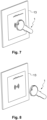
- FIGS 7 to 9 illustrate some use case examples of the mechatronic key.
- the key 1 is in close proximity of the RFID reader device 13 so that a first side of the RFID tag 11 is pointed at the RFID reader device.
- the scenario of Figure 8 differs from the scenario of Figure 7 in that in the scenario of Figure 8 , the distance between the RFID reader and the RFID tag has been increased.
- a second, different side of the RFID tag 11 is pointed at the RFID reader device 13.
- the RFID reader device 13 is able to successfully read the coding of the RFID tag without any problems irrespective of the side of the key that is pointed at the reader device.
- the key and the reader device thus form a lock system, where the reader device is configured to wirelessly read the coding of the RFID tag when the key is placed within a wireless reading distance from the reader device.
- the ring 7 could partially or entirely be made of electrically non-conductive material.
- the ring could be made of a different material than the key blade 3, or they both could alternatively be made of the same electrically non-conductive material.
- the opening 15 would not significantly improve the usability of the key 1 in terms of the tag reading performance.
Landscapes
- Engineering & Computer Science (AREA)
- Physics & Mathematics (AREA)
- General Physics & Mathematics (AREA)
- Manufacturing & Machinery (AREA)
- Computer Hardware Design (AREA)
- Microelectronics & Electronic Packaging (AREA)
- Theoretical Computer Science (AREA)
- Computer Networks & Wireless Communication (AREA)
- Lock And Its Accessories (AREA)
Claims (14)
- Mechatronischer Schlüssel (1), umfassend ein Schlüsselblatt (3) zum Einführen in einen Schlüsselkanal, und einen Schlüsselkopf (5) zum Greifen des Schlüssels (1), wobei der Schlüsselkopf (5) einen Ring (7), der einen Hohlraum (9) umgibt, und eine elektrische Schaltung (11) umfasst, die zumindest teilweise in dem Hohlraum (9) platziert ist, wobei die elektrische Schaltung (11) dazu konfiguriert ist, drahtlos mit einer Lesevorrichtung (13) zu kommunizieren, wobei der Schlüsselkopf (5) ferner eine Abdeckanordnung (21, 22) zum Schützen der elektrischen Schaltung (11) umfasst, und wobei die Abdeckanordnung (21, 22) ein Griffelement zum Greifen des Schlüsselkopfes (5) bildet, wobei der Ring (7) eine Öffnung (15) umfasst, wodurch ein unterbrochener Abschnitt entlang eines Ringumfangs des Rings (7) entsteht, wobei die Öffnung (15) entlang des Ringumfangs eine Länge zwischen 0,1 mm und 20 mm aufweist, dadurch gekennzeichnet, dass die Abdeckanordnung (21, 22) ein erstes Abdeckelement (21) und ein zweites Abdeckelement (22) umfasst, wobei mindestens eines der ersten und zweiten Abdeckelemente (21, 22) ein jeweiliges hervorstehendes Merkmal (25) auf einer Innenfläche des jeweiligen Abdeckelements (21, 22) umfasst, und wobei die hervorstehendes Merkmal (25) als geschlossener oder gebrochener Reliefring (25) ausgebildet ist und geformt und dimensioniert ist, um mit dem Ring (7) in Eingriff zu kommen.
- Schlüssel (1) nach Anspruch 1, wobei ein ununterbrochener Ringabschnitt in einem Ringmittelbereich vorhanden ist, der durch eine durch das Schlüsselblatt (3) definierte Längsachse (A1) des Schlüssels (1) definiert ist.
- Schlüssel (1) nach einem der vorhergehenden Ansprüche, wobei der Ring (7) einen Außenumfang oder einen Außenumfangsabschnitt des Schlüsselkopfes (5) bildet.
- Schlüssel (1) nach einem der vorhergehenden Ansprüche, wobei die Abdeckanordnung (21, 22) ein erstes Abdeckelement (21) und ein zweites, unterschiedliches Abdeckelement (22) umfasst, so dass das erste Abdeckelement (21) auf einer ersten Seite des Schlüsselkopfes (5) angeordnet ist, und das zweite Abdeckelement (22) ist auf einer zweiten, gegenüberliegenden Seite des Schlüsselkopfes (5) angeordnet ist.
- Schlüssel (1) nach einem der vorhergehenden Ansprüche, wobei das jeweilige hervorstehende Merkmal (25) so geformt und bemessen ist, dass es auch mit der elektrischen Schaltung (11) in Eingriff kommt, um sie innerhalb des Hohlraums (9) an Ort und Stelle zu halten.
- Schlüssel (1) nach einem der vorhergehenden Ansprüche, wobei die Abdeckanordnung (21, 22) die Öffnung (15) in Umfangsrichtung ausfüllt oder im Wesentlichen ausfüllt.
- Schlüssel (1) nach einem der vorhergehenden Ansprüche, wobei die elektrische Schaltung (11) innerhalb des Hohlraums (9) in Bezug auf den Ring (7) symmetrisch positioniert ist.
- Schlüssel (1) nach einem der vorhergehenden Ansprüche, wobei die elektrische Schaltung (11) innerhalb des Hohlraums durch die Abdeckanordnung (21, 22) an Ort und Stelle gehalten wird.
- Schlüssel (1) nach einem der vorhergehenden Ansprüche, wobei die Abdeckanordnung (21, 22) mit dem Ring (7) durch mindestens eine der folgenden Verbindungen gekoppelt ist: eine Presssitzverbindung, eine Klammeranordnung, Kleben und eine Schweissverbindung.
- Schlüssel (1) nach einem der vorhergehenden Ansprüche, wobei der Schlüsselkopf (5) einen Durchgang im Wesentlichen orthogonal zu einer Schlüssellängsachse (A1) umfasst, wobei der Durchgang zumindest teilweise durch eine Aussparung (29) in der Abdeckanordnung (21, 22) oder ein Durchgangsloch quer durch die Abdeckanordnung (21, 22) orthogonal zur Schlüssellängsachse (A1) gebildet ist, und wobei die elektrische Schaltung (11) so geformt und bemessen ist, dass sie einen Freiraum für den Durchgang lässt.
- Schlüssel (1) nach einem der vorhergehenden Ansprüche, wobei die Dicke der elektrischen Schaltung (11) orthogonal zu einer Schlüssellängsachse (A1) gleich oder kleiner ist als die Dicke des Rings (7) orthogonal zur Schlüssellängsachse (A1), oder wobei die Dicke der elektrischen Schaltung (11) orthogonal zu einer Schlüssellängsachse (A1) grösser ist als die Dicke des Rings (7) orthogonal zu der Schlüssellängsachse (A1).
- Schlüssel (1) nach einem der vorhergehenden Ansprüche, wobei der Ring (7) zumindest aus einer Kupferlegierung mit Nickel hergestellt ist.
- Schlüssel (1) nach einem der vorhergehenden Ansprüche, wobei die elektrische Schaltung (11) ein Funkfrequenzidentifikations-Tag (11) ist.
- Schlosssystem, umfassend den Schlüssel (1) nach einem der vorhergehenden Ansprüche, und ferner umfassend eine Lesevorrichtung (13), die dazu konfiguriert ist, drahtlos eine Codierung der elektrischen Schaltung (11) zu lesen, wenn der Schlüssel (1) in einem drahtlosen Leseabstand zur Lesevorrichtung (13) angeordnet ist.
Applications Claiming Priority (1)
| Application Number | Priority Date | Filing Date | Title |
|---|---|---|---|
| CH000329/2021A CH718481B1 (de) | 2021-03-29 | 2021-03-29 | Mechatronischer Schlüssel. |
Publications (3)
| Publication Number | Publication Date |
|---|---|
| EP4067608A1 EP4067608A1 (de) | 2022-10-05 |
| EP4067608C0 EP4067608C0 (de) | 2024-05-01 |
| EP4067608B1 true EP4067608B1 (de) | 2024-05-01 |
Family
ID=80787383
Family Applications (1)
| Application Number | Title | Priority Date | Filing Date |
|---|---|---|---|
| EP22161696.4A Active EP4067608B1 (de) | 2021-03-29 | 2022-03-11 | Mechatronischer schlüssel |
Country Status (2)
| Country | Link |
|---|---|
| EP (1) | EP4067608B1 (de) |
| CH (1) | CH718481B1 (de) |
Family Cites Families (8)
| Publication number | Priority date | Publication date | Assignee | Title |
|---|---|---|---|---|
| US6427504B1 (en) * | 1993-08-26 | 2002-08-06 | Strattec Security Corporation | Key assembly for vehicle ignition locks |
| JP2677769B2 (ja) * | 1994-09-29 | 1997-11-17 | 株式会社アルファ | 電子部品内蔵キー装置及びその製造方法 |
| US6308542B1 (en) * | 1996-10-11 | 2001-10-30 | Ortech Co. | Key assemblies and methods of making same |
| IT247804Y1 (it) * | 1999-12-10 | 2002-09-10 | Silcon Plastic Srl | Struttura di chiave |
| US20030209044A1 (en) * | 2002-05-07 | 2003-11-13 | Jeffrey Plate | Overmolded key assembly with insert and method of making |
| US7047777B2 (en) * | 2004-04-19 | 2006-05-23 | Hurd Corporation | Key with transponder and rotating shuttle |
| FR2899264A1 (fr) * | 2006-03-30 | 2007-10-05 | Olivier Bascoul | Cle adaptee pour pouvoir etre assemblee avec une lampe et cle lumineuse |
| DE102015205213A1 (de) * | 2015-03-23 | 2016-09-29 | Bks Gmbh | Profilzylinderschlüssel |
-
2021
- 2021-03-29 CH CH000329/2021A patent/CH718481B1/de unknown
-
2022
- 2022-03-11 EP EP22161696.4A patent/EP4067608B1/de active Active
Also Published As
| Publication number | Publication date |
|---|---|
| EP4067608A1 (de) | 2022-10-05 |
| CH718481B1 (de) | 2024-01-15 |
| EP4067608C0 (de) | 2024-05-01 |
| CH718481A1 (de) | 2022-09-30 |
Similar Documents
| Publication | Publication Date | Title |
|---|---|---|
| EP2195767B1 (de) | Rfid-transponder und verfahren | |
| US5878611A (en) | Flat key | |
| US9580932B2 (en) | Two-piece key assembly | |
| US5195341A (en) | Electronic cylinder lock with inductively coupled key | |
| KR101758444B1 (ko) | 전자 카드를 제조하는 방법 | |
| FI108309B (fi) | Sulkusylinteri ja litteä avain | |
| DK2915158T3 (en) | Safe sealing device and method | |
| US6927670B1 (en) | Conventional mechanical lock cylinders and keys with electronic access control feature | |
| US20200242868A1 (en) | Electronic lock and interchangeable shackles | |
| KR101798104B1 (ko) | 안테나를 내장한 비접촉식 금속카드 | |
| CN208073145U (zh) | 带无线通信器件的钥匙及用于带无线通信器件的钥匙的锁 | |
| EP4067608B1 (de) | Mechatronischer schlüssel | |
| US7047777B2 (en) | Key with transponder and rotating shuttle | |
| CN107430830B (zh) | 安全锁 | |
| CN101827989B (zh) | 用于开锁的带有加强的位置锁定的可枢转钥匙 | |
| US20230292889A1 (en) | Jewelry ring having a rfid transponder and a reading arrangement | |
| CN105121761A (zh) | 圆筒锁以及这种锁和钥匙的组合 | |
| EP2716843B1 (de) | Hebelartiger griff und verriegelungselement für den hebelartigen griff | |
| US20050128053A1 (en) | Portable modular wirefree identification signal transmitter and wirefree access control system | |
| KR101798103B1 (ko) | 안테나를 내장한 비접촉식 금속카드 | |
| CN210828677U (zh) | 一种电子玻璃门锁 | |
| JP5563772B2 (ja) | キーヘッドカバー | |
| EP3480736B1 (de) | Elektrische identifizierungsvorrichtung | |
| KR20090006413U (ko) | 알에프아이디 카드용 테두리보강테 | |
| JP7753137B2 (ja) | コイン型非接触情報媒体およびその製造方法 |
Legal Events
| Date | Code | Title | Description |
|---|---|---|---|
| PUAI | Public reference made under article 153(3) epc to a published international application that has entered the european phase |
Free format text: ORIGINAL CODE: 0009012 |
|
| STAA | Information on the status of an ep patent application or granted ep patent |
Free format text: STATUS: THE APPLICATION HAS BEEN PUBLISHED |
|
| AK | Designated contracting states |
Kind code of ref document: A1 Designated state(s): AL AT BE BG CH CY CZ DE DK EE ES FI FR GB GR HR HU IE IS IT LI LT LU LV MC MK MT NL NO PL PT RO RS SE SI SK SM TR |
|
| STAA | Information on the status of an ep patent application or granted ep patent |
Free format text: STATUS: REQUEST FOR EXAMINATION WAS MADE |
|
| 17P | Request for examination filed |
Effective date: 20230405 |
|
| RBV | Designated contracting states (corrected) |
Designated state(s): AL AT BE BG CH CY CZ DE DK EE ES FI FR GB GR HR HU IE IS IT LI LT LU LV MC MK MT NL NO PL PT RO RS SE SI SK SM TR |
|
| RIC1 | Information provided on ipc code assigned before grant |
Ipc: E05B 35/00 20060101ALN20230913BHEP Ipc: E05B 47/00 20060101ALN20230913BHEP Ipc: E05B 47/06 20060101ALN20230913BHEP Ipc: E05B 49/00 20060101ALN20230913BHEP Ipc: E05B 35/14 20060101ALI20230913BHEP Ipc: G07C 9/00 20200101ALI20230913BHEP Ipc: E05B 19/04 20060101AFI20230913BHEP |
|
| GRAP | Despatch of communication of intention to grant a patent |
Free format text: ORIGINAL CODE: EPIDOSNIGR1 |
|
| STAA | Information on the status of an ep patent application or granted ep patent |
Free format text: STATUS: GRANT OF PATENT IS INTENDED |
|
| INTG | Intention to grant announced |
Effective date: 20231027 |
|
| GRAS | Grant fee paid |
Free format text: ORIGINAL CODE: EPIDOSNIGR3 |
|
| GRAA | (expected) grant |
Free format text: ORIGINAL CODE: 0009210 |
|
| STAA | Information on the status of an ep patent application or granted ep patent |
Free format text: STATUS: THE PATENT HAS BEEN GRANTED |
|
| AK | Designated contracting states |
Kind code of ref document: B1 Designated state(s): AL AT BE BG CH CY CZ DE DK EE ES FI FR GB GR HR HU IE IS IT LI LT LU LV MC MK MT NL NO PL PT RO RS SE SI SK SM TR |
|
| REG | Reference to a national code |
Ref country code: GB Ref legal event code: FG4D |
|
| REG | Reference to a national code |
Ref country code: CH Ref legal event code: EP |
|
| REG | Reference to a national code |
Ref country code: DE Ref legal event code: R096 Ref document number: 602022003113 Country of ref document: DE |
|
| REG | Reference to a national code |
Ref country code: IE Ref legal event code: FG4D |
|
| U01 | Request for unitary effect filed |
Effective date: 20240528 |
|
| U07 | Unitary effect registered |
Designated state(s): AT BE BG DE DK EE FI FR IT LT LU LV MT NL PT SE SI Effective date: 20240606 |
|
| PG25 | Lapsed in a contracting state [announced via postgrant information from national office to epo] |
Ref country code: IS Free format text: LAPSE BECAUSE OF FAILURE TO SUBMIT A TRANSLATION OF THE DESCRIPTION OR TO PAY THE FEE WITHIN THE PRESCRIBED TIME-LIMIT Effective date: 20240901 |
|
| PG25 | Lapsed in a contracting state [announced via postgrant information from national office to epo] |
Ref country code: HR Free format text: LAPSE BECAUSE OF FAILURE TO SUBMIT A TRANSLATION OF THE DESCRIPTION OR TO PAY THE FEE WITHIN THE PRESCRIBED TIME-LIMIT Effective date: 20240501 |
|
| PG25 | Lapsed in a contracting state [announced via postgrant information from national office to epo] |
Ref country code: GR Free format text: LAPSE BECAUSE OF FAILURE TO SUBMIT A TRANSLATION OF THE DESCRIPTION OR TO PAY THE FEE WITHIN THE PRESCRIBED TIME-LIMIT Effective date: 20240802 |
|
| PG25 | Lapsed in a contracting state [announced via postgrant information from national office to epo] |
Ref country code: ES Free format text: LAPSE BECAUSE OF FAILURE TO SUBMIT A TRANSLATION OF THE DESCRIPTION OR TO PAY THE FEE WITHIN THE PRESCRIBED TIME-LIMIT Effective date: 20240501 |
|
| PG25 | Lapsed in a contracting state [announced via postgrant information from national office to epo] |
Ref country code: PL Free format text: LAPSE BECAUSE OF FAILURE TO SUBMIT A TRANSLATION OF THE DESCRIPTION OR TO PAY THE FEE WITHIN THE PRESCRIBED TIME-LIMIT Effective date: 20240501 |
|
| PG25 | Lapsed in a contracting state [announced via postgrant information from national office to epo] |
Ref country code: PL Free format text: LAPSE BECAUSE OF FAILURE TO SUBMIT A TRANSLATION OF THE DESCRIPTION OR TO PAY THE FEE WITHIN THE PRESCRIBED TIME-LIMIT Effective date: 20240501 Ref country code: NO Free format text: LAPSE BECAUSE OF FAILURE TO SUBMIT A TRANSLATION OF THE DESCRIPTION OR TO PAY THE FEE WITHIN THE PRESCRIBED TIME-LIMIT Effective date: 20240801 Ref country code: IS Free format text: LAPSE BECAUSE OF FAILURE TO SUBMIT A TRANSLATION OF THE DESCRIPTION OR TO PAY THE FEE WITHIN THE PRESCRIBED TIME-LIMIT Effective date: 20240901 Ref country code: HR Free format text: LAPSE BECAUSE OF FAILURE TO SUBMIT A TRANSLATION OF THE DESCRIPTION OR TO PAY THE FEE WITHIN THE PRESCRIBED TIME-LIMIT Effective date: 20240501 Ref country code: GR Free format text: LAPSE BECAUSE OF FAILURE TO SUBMIT A TRANSLATION OF THE DESCRIPTION OR TO PAY THE FEE WITHIN THE PRESCRIBED TIME-LIMIT Effective date: 20240802 Ref country code: ES Free format text: LAPSE BECAUSE OF FAILURE TO SUBMIT A TRANSLATION OF THE DESCRIPTION OR TO PAY THE FEE WITHIN THE PRESCRIBED TIME-LIMIT Effective date: 20240501 Ref country code: RS Free format text: LAPSE BECAUSE OF FAILURE TO SUBMIT A TRANSLATION OF THE DESCRIPTION OR TO PAY THE FEE WITHIN THE PRESCRIBED TIME-LIMIT Effective date: 20240801 |
|
| PG25 | Lapsed in a contracting state [announced via postgrant information from national office to epo] |
Ref country code: CZ Free format text: LAPSE BECAUSE OF FAILURE TO SUBMIT A TRANSLATION OF THE DESCRIPTION OR TO PAY THE FEE WITHIN THE PRESCRIBED TIME-LIMIT Effective date: 20240501 |
|
| PG25 | Lapsed in a contracting state [announced via postgrant information from national office to epo] |
Ref country code: RO Free format text: LAPSE BECAUSE OF FAILURE TO SUBMIT A TRANSLATION OF THE DESCRIPTION OR TO PAY THE FEE WITHIN THE PRESCRIBED TIME-LIMIT Effective date: 20240501 Ref country code: SK Free format text: LAPSE BECAUSE OF FAILURE TO SUBMIT A TRANSLATION OF THE DESCRIPTION OR TO PAY THE FEE WITHIN THE PRESCRIBED TIME-LIMIT Effective date: 20240501 |
|
| PG25 | Lapsed in a contracting state [announced via postgrant information from national office to epo] |
Ref country code: SM Free format text: LAPSE BECAUSE OF FAILURE TO SUBMIT A TRANSLATION OF THE DESCRIPTION OR TO PAY THE FEE WITHIN THE PRESCRIBED TIME-LIMIT Effective date: 20240501 |
|
| PG25 | Lapsed in a contracting state [announced via postgrant information from national office to epo] |
Ref country code: SM Free format text: LAPSE BECAUSE OF FAILURE TO SUBMIT A TRANSLATION OF THE DESCRIPTION OR TO PAY THE FEE WITHIN THE PRESCRIBED TIME-LIMIT Effective date: 20240501 Ref country code: SK Free format text: LAPSE BECAUSE OF FAILURE TO SUBMIT A TRANSLATION OF THE DESCRIPTION OR TO PAY THE FEE WITHIN THE PRESCRIBED TIME-LIMIT Effective date: 20240501 Ref country code: RO Free format text: LAPSE BECAUSE OF FAILURE TO SUBMIT A TRANSLATION OF THE DESCRIPTION OR TO PAY THE FEE WITHIN THE PRESCRIBED TIME-LIMIT Effective date: 20240501 Ref country code: CZ Free format text: LAPSE BECAUSE OF FAILURE TO SUBMIT A TRANSLATION OF THE DESCRIPTION OR TO PAY THE FEE WITHIN THE PRESCRIBED TIME-LIMIT Effective date: 20240501 |
|
| REG | Reference to a national code |
Ref country code: DE Ref legal event code: R097 Ref document number: 602022003113 Country of ref document: DE |
|
| U20 | Renewal fee for the european patent with unitary effect paid |
Year of fee payment: 4 Effective date: 20250120 |
|
| PLBE | No opposition filed within time limit |
Free format text: ORIGINAL CODE: 0009261 |
|
| STAA | Information on the status of an ep patent application or granted ep patent |
Free format text: STATUS: NO OPPOSITION FILED WITHIN TIME LIMIT |
|
| 26N | No opposition filed |
Effective date: 20250204 |
|
| PGFP | Annual fee paid to national office [announced via postgrant information from national office to epo] |
Ref country code: CH Payment date: 20250401 Year of fee payment: 4 |
|
| PG25 | Lapsed in a contracting state [announced via postgrant information from national office to epo] |
Ref country code: MC Free format text: LAPSE BECAUSE OF FAILURE TO SUBMIT A TRANSLATION OF THE DESCRIPTION OR TO PAY THE FEE WITHIN THE PRESCRIBED TIME-LIMIT Effective date: 20240501 |
|
| PG25 | Lapsed in a contracting state [announced via postgrant information from national office to epo] |
Ref country code: IE Free format text: LAPSE BECAUSE OF NON-PAYMENT OF DUE FEES Effective date: 20250311 |
|
| U20 | Renewal fee for the european patent with unitary effect paid |
Year of fee payment: 5 Effective date: 20260203 |