EP4067575B1 - Self-propelled soil working machine with combined heat exchanger cooling and engine room ventilation - Google Patents
Self-propelled soil working machine with combined heat exchanger cooling and engine room ventilation Download PDFInfo
- Publication number
- EP4067575B1 EP4067575B1 EP22164606.0A EP22164606A EP4067575B1 EP 4067575 B1 EP4067575 B1 EP 4067575B1 EP 22164606 A EP22164606 A EP 22164606A EP 4067575 B1 EP4067575 B1 EP 4067575B1
- Authority
- EP
- European Patent Office
- Prior art keywords
- heat exchanger
- air flow
- machine
- earth working
- working machine
- Prior art date
- Legal status (The legal status is an assumption and is not a legal conclusion. Google has not performed a legal analysis and makes no representation as to the accuracy of the status listed.)
- Active
Links
- 238000001816 cooling Methods 0.000 title claims description 103
- 238000009423 ventilation Methods 0.000 title claims description 69
- 239000002689 soil Substances 0.000 title description 44
- 238000003801 milling Methods 0.000 claims description 34
- 239000002826 coolant Substances 0.000 claims description 27
- 238000002156 mixing Methods 0.000 claims description 25
- 238000006073 displacement reaction Methods 0.000 claims description 6
- 238000011144 upstream manufacturing Methods 0.000 claims description 6
- 239000003381 stabilizer Substances 0.000 claims description 2
- 239000003570 air Substances 0.000 description 160
- 238000002485 combustion reaction Methods 0.000 description 29
- 238000003971 tillage Methods 0.000 description 27
- 239000010720 hydraulic oil Substances 0.000 description 10
- 238000004140 cleaning Methods 0.000 description 6
- 239000000203 mixture Substances 0.000 description 6
- 239000012080 ambient air Substances 0.000 description 5
- 230000015572 biosynthetic process Effects 0.000 description 5
- 238000005755 formation reaction Methods 0.000 description 5
- 239000007788 liquid Substances 0.000 description 5
- 238000009434 installation Methods 0.000 description 4
- 239000000463 material Substances 0.000 description 4
- 238000007789 sealing Methods 0.000 description 4
- 230000005540 biological transmission Effects 0.000 description 3
- 238000011068 loading method Methods 0.000 description 2
- 239000002184 metal Substances 0.000 description 2
- 229910052751 metal Inorganic materials 0.000 description 2
- 239000003921 oil Substances 0.000 description 2
- 230000005855 radiation Effects 0.000 description 2
- 230000000712 assembly Effects 0.000 description 1
- 238000000429 assembly Methods 0.000 description 1
- 238000007664 blowing Methods 0.000 description 1
- 238000010516 chain-walking reaction Methods 0.000 description 1
- 230000001427 coherent effect Effects 0.000 description 1
- 230000000295 complement effect Effects 0.000 description 1
- 238000010276 construction Methods 0.000 description 1
- 238000011109 contamination Methods 0.000 description 1
- 238000005553 drilling Methods 0.000 description 1
- 239000000428 dust Substances 0.000 description 1
- 238000004146 energy storage Methods 0.000 description 1
- 238000000605 extraction Methods 0.000 description 1
- 239000000446 fuel Substances 0.000 description 1
- 238000000227 grinding Methods 0.000 description 1
- 238000005192 partition Methods 0.000 description 1
- 230000000149 penetrating effect Effects 0.000 description 1
- 239000004033 plastic Substances 0.000 description 1
- 238000005381 potential energy Methods 0.000 description 1
- 238000001556 precipitation Methods 0.000 description 1
- 230000001681 protective effect Effects 0.000 description 1
- 230000001105 regulatory effect Effects 0.000 description 1
- 238000000926 separation method Methods 0.000 description 1
- 239000007787 solid Substances 0.000 description 1
- 238000003466 welding Methods 0.000 description 1
Images


Classifications
-
- E—FIXED CONSTRUCTIONS
- E01—CONSTRUCTION OF ROADS, RAILWAYS, OR BRIDGES
- E01C—CONSTRUCTION OF, OR SURFACES FOR, ROADS, SPORTS GROUNDS, OR THE LIKE; MACHINES OR AUXILIARY TOOLS FOR CONSTRUCTION OR REPAIR
- E01C23/00—Auxiliary devices or arrangements for constructing, repairing, reconditioning, or taking-up road or like surfaces
- E01C23/06—Devices or arrangements for working the finished surface; Devices for repairing or reconditioning the surface of damaged paving; Recycling in place or on the road
- E01C23/08—Devices or arrangements for working the finished surface; Devices for repairing or reconditioning the surface of damaged paving; Recycling in place or on the road for roughening or patterning; for removing the surface down to a predetermined depth high spots or material bonded to the surface, e.g. markings; for maintaining earth roads, clay courts or like surfaces by means of surface working tools, e.g. scarifiers, levelling blades
- E01C23/085—Devices or arrangements for working the finished surface; Devices for repairing or reconditioning the surface of damaged paving; Recycling in place or on the road for roughening or patterning; for removing the surface down to a predetermined depth high spots or material bonded to the surface, e.g. markings; for maintaining earth roads, clay courts or like surfaces by means of surface working tools, e.g. scarifiers, levelling blades using power-driven tools, e.g. vibratory tools
- E01C23/088—Rotary tools, e.g. milling drums
-
- F—MECHANICAL ENGINEERING; LIGHTING; HEATING; WEAPONS; BLASTING
- F01—MACHINES OR ENGINES IN GENERAL; ENGINE PLANTS IN GENERAL; STEAM ENGINES
- F01P—COOLING OF MACHINES OR ENGINES IN GENERAL; COOLING OF INTERNAL-COMBUSTION ENGINES
- F01P5/00—Pumping cooling-air or liquid coolants
- F01P5/02—Pumping cooling-air; Arrangements of cooling-air pumps, e.g. fans or blowers
-
- B—PERFORMING OPERATIONS; TRANSPORTING
- B60—VEHICLES IN GENERAL
- B60K—ARRANGEMENT OR MOUNTING OF PROPULSION UNITS OR OF TRANSMISSIONS IN VEHICLES; ARRANGEMENT OR MOUNTING OF PLURAL DIVERSE PRIME-MOVERS IN VEHICLES; AUXILIARY DRIVES FOR VEHICLES; INSTRUMENTATION OR DASHBOARDS FOR VEHICLES; ARRANGEMENTS IN CONNECTION WITH COOLING, AIR INTAKE, GAS EXHAUST OR FUEL SUPPLY OF PROPULSION UNITS IN VEHICLES
- B60K11/00—Arrangement in connection with cooling of propulsion units
- B60K11/02—Arrangement in connection with cooling of propulsion units with liquid cooling
- B60K11/04—Arrangement or mounting of radiators, radiator shutters, or radiator blinds
-
- B—PERFORMING OPERATIONS; TRANSPORTING
- B60—VEHICLES IN GENERAL
- B60K—ARRANGEMENT OR MOUNTING OF PROPULSION UNITS OR OF TRANSMISSIONS IN VEHICLES; ARRANGEMENT OR MOUNTING OF PLURAL DIVERSE PRIME-MOVERS IN VEHICLES; AUXILIARY DRIVES FOR VEHICLES; INSTRUMENTATION OR DASHBOARDS FOR VEHICLES; ARRANGEMENTS IN CONNECTION WITH COOLING, AIR INTAKE, GAS EXHAUST OR FUEL SUPPLY OF PROPULSION UNITS IN VEHICLES
- B60K11/00—Arrangement in connection with cooling of propulsion units
- B60K11/06—Arrangement in connection with cooling of propulsion units with air cooling
-
- B—PERFORMING OPERATIONS; TRANSPORTING
- B60—VEHICLES IN GENERAL
- B60K—ARRANGEMENT OR MOUNTING OF PROPULSION UNITS OR OF TRANSMISSIONS IN VEHICLES; ARRANGEMENT OR MOUNTING OF PLURAL DIVERSE PRIME-MOVERS IN VEHICLES; AUXILIARY DRIVES FOR VEHICLES; INSTRUMENTATION OR DASHBOARDS FOR VEHICLES; ARRANGEMENTS IN CONNECTION WITH COOLING, AIR INTAKE, GAS EXHAUST OR FUEL SUPPLY OF PROPULSION UNITS IN VEHICLES
- B60K11/00—Arrangement in connection with cooling of propulsion units
- B60K11/08—Air inlets for cooling; Shutters or blinds therefor
-
- E—FIXED CONSTRUCTIONS
- E01—CONSTRUCTION OF ROADS, RAILWAYS, OR BRIDGES
- E01C—CONSTRUCTION OF, OR SURFACES FOR, ROADS, SPORTS GROUNDS, OR THE LIKE; MACHINES OR AUXILIARY TOOLS FOR CONSTRUCTION OR REPAIR
- E01C23/00—Auxiliary devices or arrangements for constructing, repairing, reconditioning, or taking-up road or like surfaces
- E01C23/06—Devices or arrangements for working the finished surface; Devices for repairing or reconditioning the surface of damaged paving; Recycling in place or on the road
- E01C23/08—Devices or arrangements for working the finished surface; Devices for repairing or reconditioning the surface of damaged paving; Recycling in place or on the road for roughening or patterning; for removing the surface down to a predetermined depth high spots or material bonded to the surface, e.g. markings; for maintaining earth roads, clay courts or like surfaces by means of surface working tools, e.g. scarifiers, levelling blades
- E01C23/085—Devices or arrangements for working the finished surface; Devices for repairing or reconditioning the surface of damaged paving; Recycling in place or on the road for roughening or patterning; for removing the surface down to a predetermined depth high spots or material bonded to the surface, e.g. markings; for maintaining earth roads, clay courts or like surfaces by means of surface working tools, e.g. scarifiers, levelling blades using power-driven tools, e.g. vibratory tools
- E01C23/088—Rotary tools, e.g. milling drums
- E01C23/0885—Rotary tools, e.g. milling drums with vertical or steeply inclined rotary axis
-
- E—FIXED CONSTRUCTIONS
- E01—CONSTRUCTION OF ROADS, RAILWAYS, OR BRIDGES
- E01C—CONSTRUCTION OF, OR SURFACES FOR, ROADS, SPORTS GROUNDS, OR THE LIKE; MACHINES OR AUXILIARY TOOLS FOR CONSTRUCTION OR REPAIR
- E01C23/00—Auxiliary devices or arrangements for constructing, repairing, reconditioning, or taking-up road or like surfaces
- E01C23/06—Devices or arrangements for working the finished surface; Devices for repairing or reconditioning the surface of damaged paving; Recycling in place or on the road
- E01C23/12—Devices or arrangements for working the finished surface; Devices for repairing or reconditioning the surface of damaged paving; Recycling in place or on the road for taking-up, tearing-up, or full-depth breaking-up paving, e.g. sett extractor
- E01C23/122—Devices or arrangements for working the finished surface; Devices for repairing or reconditioning the surface of damaged paving; Recycling in place or on the road for taking-up, tearing-up, or full-depth breaking-up paving, e.g. sett extractor with power-driven tools, e.g. oscillated hammer apparatus
- E01C23/127—Devices or arrangements for working the finished surface; Devices for repairing or reconditioning the surface of damaged paving; Recycling in place or on the road for taking-up, tearing-up, or full-depth breaking-up paving, e.g. sett extractor with power-driven tools, e.g. oscillated hammer apparatus rotary, e.g. rotary hammers
-
- F—MECHANICAL ENGINEERING; LIGHTING; HEATING; WEAPONS; BLASTING
- F01—MACHINES OR ENGINES IN GENERAL; ENGINE PLANTS IN GENERAL; STEAM ENGINES
- F01P—COOLING OF MACHINES OR ENGINES IN GENERAL; COOLING OF INTERNAL-COMBUSTION ENGINES
- F01P1/00—Air cooling
-
- F—MECHANICAL ENGINEERING; LIGHTING; HEATING; WEAPONS; BLASTING
- F01—MACHINES OR ENGINES IN GENERAL; ENGINE PLANTS IN GENERAL; STEAM ENGINES
- F01P—COOLING OF MACHINES OR ENGINES IN GENERAL; COOLING OF INTERNAL-COMBUSTION ENGINES
- F01P11/00—Component parts, details, or accessories not provided for in, or of interest apart from, groups F01P1/00 - F01P9/00
- F01P11/10—Guiding or ducting cooling-air, to, or from, liquid-to-air heat exchangers
-
- F—MECHANICAL ENGINEERING; LIGHTING; HEATING; WEAPONS; BLASTING
- F01—MACHINES OR ENGINES IN GENERAL; ENGINE PLANTS IN GENERAL; STEAM ENGINES
- F01P—COOLING OF MACHINES OR ENGINES IN GENERAL; COOLING OF INTERNAL-COMBUSTION ENGINES
- F01P3/00—Liquid cooling
- F01P3/18—Arrangements or mounting of liquid-to-air heat-exchangers
-
- F—MECHANICAL ENGINEERING; LIGHTING; HEATING; WEAPONS; BLASTING
- F01—MACHINES OR ENGINES IN GENERAL; ENGINE PLANTS IN GENERAL; STEAM ENGINES
- F01P—COOLING OF MACHINES OR ENGINES IN GENERAL; COOLING OF INTERNAL-COMBUSTION ENGINES
- F01P5/00—Pumping cooling-air or liquid coolants
- F01P5/02—Pumping cooling-air; Arrangements of cooling-air pumps, e.g. fans or blowers
- F01P5/06—Guiding or ducting air to, or from, ducted fans
-
- B—PERFORMING OPERATIONS; TRANSPORTING
- B60—VEHICLES IN GENERAL
- B60Y—INDEXING SCHEME RELATING TO ASPECTS CROSS-CUTTING VEHICLE TECHNOLOGY
- B60Y2200/00—Type of vehicle
- B60Y2200/40—Special vehicles
- B60Y2200/41—Construction vehicles, e.g. graders, excavators
-
- F—MECHANICAL ENGINEERING; LIGHTING; HEATING; WEAPONS; BLASTING
- F01—MACHINES OR ENGINES IN GENERAL; ENGINE PLANTS IN GENERAL; STEAM ENGINES
- F01P—COOLING OF MACHINES OR ENGINES IN GENERAL; COOLING OF INTERNAL-COMBUSTION ENGINES
- F01P3/00—Liquid cooling
- F01P3/18—Arrangements or mounting of liquid-to-air heat-exchangers
- F01P2003/185—Arrangements or mounting of liquid-to-air heat-exchangers arranged in parallel
-
- F—MECHANICAL ENGINEERING; LIGHTING; HEATING; WEAPONS; BLASTING
- F01—MACHINES OR ENGINES IN GENERAL; ENGINE PLANTS IN GENERAL; STEAM ENGINES
- F01P—COOLING OF MACHINES OR ENGINES IN GENERAL; COOLING OF INTERNAL-COMBUSTION ENGINES
- F01P5/00—Pumping cooling-air or liquid coolants
- F01P5/02—Pumping cooling-air; Arrangements of cooling-air pumps, e.g. fans or blowers
- F01P2005/025—Pumping cooling-air; Arrangements of cooling-air pumps, e.g. fans or blowers using two or more air pumps
-
- F—MECHANICAL ENGINEERING; LIGHTING; HEATING; WEAPONS; BLASTING
- F01—MACHINES OR ENGINES IN GENERAL; ENGINE PLANTS IN GENERAL; STEAM ENGINES
- F01P—COOLING OF MACHINES OR ENGINES IN GENERAL; COOLING OF INTERNAL-COMBUSTION ENGINES
- F01P2060/00—Cooling circuits using auxiliaries
- F01P2060/02—Intercooler
Definitions
- Such a tillage machine in the form of a road milling machine is from DE 10 2014 008 749 A1 known. It is known in detail from this document to arrange both an internal combustion engine as the power source and the cooling device mentioned at the outset between a driver's cab and the rear of a road cold milling machine.
- the known heat exchanger arrangement includes two heat exchangers, which belong to different cooling circuits. In a first cooling circuit a cooling medium circulates between a heat exchanger and the internal combustion engine and emits heat from the heat exchanger again, which the cooling medium has previously absorbed from the internal combustion engine. In a second cooling circuit, hydraulic oil circulates as the heat-emitting cooling medium in the heat exchanger, which is used to operate the hydraulic motors of the travel drive.
- the cooling air streams passing through the individual heat exchangers are strictly separated from one another by partition walls, since due to the operating characteristics of the known road cold milling machine there is, to a certain extent, a complementary thermal load on the cooling medium of the internal combustion engine on the one hand and on the hydraulic oil on the other.
- the internal combustion engine and its cooling medium are thermally only slightly stressed, but the hydraulic oil of the hydraulic motors forming the travel drive is very.
- the hydraulic oil is thermally only slightly loaded, but the internal combustion engine and its cooling medium is very.
- the first-mentioned technical teaching has the disadvantage that the air moving through the heat exchanger has a higher temperature than the pure fresh air sucked in due to the added heated air that was sucked out of the area of the internal combustion engine, which in the heat exchanger causes the heat transfer from cooling medium to air and thus reduces its efficiency.
- the second-mentioned technical teaching has the one disadvantage that fans operated by pressure are less efficient than fans operated by suction with the same power, and has the further disadvantage that on the pressure side, in particular, the air that is pushed towards the internal combustion engine flows along almost uncontrollable and unpredictable flow paths and leaks into the outside environment at any, often disadvantageous, locations on the soil tillage implement.
- From the EP 3 081 421 B1 is another soil cultivating machine designed as a drilling rig, in which an internal combustion engine as a heat source and a heat exchanger arrangement are arranged on the suction side of the fan arrangement, one behind the other in the air flow generated by the fan arrangement.
- the fan arrangement conveys air heated by the internal combustion engine through the heat exchanger arrangement, which leads to the disadvantages described above.
- Due to the series arrangement the internal combustion engine is in an environment with a considerable negative pressure compared to the atmosphere during the entire fan operation.
- an above-average amount of dirt from the dust-laden construction site environment of the known soil tillage machine is conveyed almost continuously to the internal combustion engine.
- the ones from the EP 3 081 421 B1 known fan arrangement is arranged obliquely with respect to a longitudinal axis of the fan duct carrying it, in order to be able to achieve the largest possible fan surface with a given duct cross section.
- This object is achieved by the present invention on a soil cultivation machine mentioned at the outset in that the ventilation volume is arranged downstream of the heat exchanger arrangement in relation to the cooling air flow, so that the ventilation air flow generated by the fan arrangement is on the cooling air flow downstream of the heat exchanger arrangement and upstream of the fan arrangement meets.
- the fan arrangement is operated with suction, which is not only the most effective mode of operation of a fan arrangement, but also ensures a possibility of determining where the heat heated by the heat exchanger arrangement and/or by the power source goes Air can be blown away from the soil tillage implement.
- the ventilation air flow extracted from the ventilation volume of the power source and heated by the power source whose temperature inevitably increases during operation, only meets the cooling air flow after it has passed the heat exchanger arrangement. This ensures that the heat exchanger arrangement is passed by the coolest possible air flow, which, due to the higher temperature difference between the cooling medium flowing through the heat exchanger arrangement and the air flow passing through, ensures greater convective heat transport from the heat exchanger arrangement than when a heated ventilation air flow is mixed in the case would be.
- the power source is also efficiently ventilated, since the area around the power source, i.e. the ventilation volume which is at least adjacent to the power source and preferably at least partially surrounds the power source, is not flowed around by air which had previously been caused by heat transfer from the heat exchanger arrangement to the air was heated.
- the heat exchanger assembly can be operated effectively, and the power source, which is always heated during operation, can be ventilated effectively.
- Another advantage of the invention is that only part of the total amount of air conveyed by the fan arrangement is sucked in from the ventilation volume near the power source, which reduces the negative pressure in the area surrounding the power source and thus the entry of dirt into this area compared to the prior art according to EP 3 081 421 B1 is reduced.
- the starting point of both the cooling air flow and the ventilation air flow is preferably the outside environment and thus the ambient atmosphere of the soil treatment machine, without one of the air flows convectively absorbing heat from another functional device before reaching the heat exchanger arrangement or the power source. At most, air sucked in by the fan arrangement flows through a cover of the heat exchanger arrangement and/or a cover of the power source from the outside environment to the heat exchanger arrangement or to the power source.
- the power source is preferably an internal combustion engine, with a diesel internal combustion engine being preferred as the internal combustion engine. Diesel internal combustion engines can be operated stationary with good efficiency and low emissions. However, it is not intended to exclude that a spark ignition engine or other type of thermal or electric prime mover is used as the power source or that the power source includes one or more fuel cells.
- the power source can be a turbocharged internal combustion engine. The power source is, so to speak, a power plant carried along by the soil tillage machine, which provides the power required for the operation of the soil tillage machine.
- the soil treatment machine can, in a manner known per se, comprise one or more power converters, which convert the power provided by the power source in one form into power provided in another form.
- the working device for tillage of a mechanical output member of the power source such as a crankshaft, are mechanically driven with the interposition of gears.
- a hydraulic pump which converts the power provided by the power source into potential energy in the form of an increased pressure level of a hydraulic oil, can also be operated, for example via an auxiliary output shaft of such a transmission, in particular a pump transfer case.
- power from the power source can be converted from mechanical power into electrical power via a generator.
- a heat source may be disposed separate from, and preferably spaced from, the heat exchanger assembly, leading away from which the fan assembly generates a ventilation airflow in operation to ventilate the heat source.
- the heat source which can be an electrical energy storage arrangement or a transmission, for example, what was said in the present application for the power source applies.
- the working device for tilling the soil is preferably a soil-removing working device.
- a "passing" of the heat exchanger arrangement by the cooling air flow refers to any type of flow of the cooling air flow past the heat exchanger arrangement with convective removal of heat from the heat exchanger arrangement by the cooling air flow.
- the cooling air flow can flow co-currently or countercurrently along a heat transfer surface of the heat exchanger arrangement in the same or opposite direction to the flow direction of a cooling medium flowing on the other side of the heat transfer surface.
- the heat exchanger arrangement is preferably a cross-flow heat exchanger arrangement, in which the cooling air flow is transverse to the flow direction of the heat exchanger arrangement Cooling medium flows.
- the heat exchanger arrangement can have cooling ducts guiding the cooling air flow through which the cooling air flow can flow.
- the cooling airflow on the one hand and the ventilation airflow on the other hand are sucked in separately from one another by the fan arrangement and blown off into the outside environment after passing through the fan arrangement.
- a consistent separation of the two air flows requires the establishment of corresponding flow channels, which represents an increased effort and leads to a complicated flow control if the entire heat exchanger arrangement is to be able to flow through the entire heat exchanger arrangement for the cooling air flow.
- Increased effort and increased complexity increase the susceptibility to failure.
- a mixing volume is provided between the heat exchanger arrangement and the fan arrangement, in which volume the cooling air flow and the ventilation air flow mix.
- cooling airflow and ventilation airflow mix By the time the cooling airflow and ventilation airflow mix, they have already done their job of dissipating heat as convective airflows and can flow together and mix as exhaust air through the fan assembly without having to fear any impact on efficiency whose pressure side are conveyed and preferably blown off into the outside environment.
- the floor-working machine in particular its cooling device, can have a pre-assembled air flow assembly, the air flow assembly including the fan arrangement, the heat exchanger arrangement and a frame supporting the fan assembly and the heat exchanger assembly.
- the air flow subassembly can thus be easily preassembled at a separate assembly station and fastened as a preassembled subassembly to the soil tillage machine, in particular to its machine frame.
- the frame may be a truss frame having a plurality of rods to which the fan assembly and the heat exchanger assembly are supported.
- a skeletal truss frame is relatively light in weight.
- the frame can have a housing section that at least partially encloses the mixing volume.
- the frame can have a frame skin and for this purpose, for example, be built and/or formed at least in sections from sheet metal and/or plastic surfaces. In this way it can be ensured that the fan arrangement actually sucks in only or predominantly the cooling air flow passing the heat exchanger arrangement and the ventilation air flow drawn off from the power source, but no false air from other areas of the soil treatment machine. It can thus be prevented that the fan arrangement sucks in air from areas of the soil treatment machine that do not require convective cooling and/or ventilation.
- the fan arrangement is arranged at a distance from the heat exchanger arrangement.
- a particularly good use of space results when the fan arrangement and the heat exchanger arrangement are rotationally displaced relative to one another about a pivot axis. Then different areas of the fan arrangement on the one hand and the heat exchanger arrangement on the other hand have different distances from each other. For the flow paths from the heat exchanger assembly to the fan assembly are short.
- the fan arrangement and the heat exchanger arrangement can be arranged translationally displaced along a displacement axis. However, the translatory displacement of the heat exchanger arrangement and the fan arrangement generally requires more installation space than a rotary displacement.
- the fan arrangement is preferably a substantially planar fan arrangement.
- "Even” is not to be understood strictly mathematically, but in such a way that the fan arrangement has significantly larger dimensions in two mutually orthogonal spatial directions than in a third spatial direction orthogonal to the named spatial directions, which is particularly preferably the flow direction of the fan arrangement along which the exhaust air flows through the fan assembly.
- An axis of rotation of at least one fan of the fan arrangement preferably runs along the third spatial direction, preferably, if the fan arrangement comprises a plurality of fans, all axes of rotation of the plurality of fans.
- the heat exchanger arrangement is also an essentially planar heat exchanger arrangement.
- the heat exchanger arrangement has a significantly larger dimension along two mutually orthogonal spatial directions than in a third spatial direction orthogonal to the two spatial directions, which is preferably a flow direction along which the cooling air flow flows through the heat exchanger arrangement, which is preferably designed as a cross-flow heat exchanger arrangement .
- the pivot axis about which the two arrangements are rotationally displaced relative to one another preferably runs parallel to each design plane of the two arrangements.
- the area of the heat exchanger arrangement through which flow can take place is preferably larger than the area of the fan arrangement through which flow can take place, so that the largest possible heat transfer area can be provided on the heat exchanger arrangement.
- the surface of a fan of the fan arrangement through which air can flow is preferably circular or ring-shaped, so that it can approach a rotating fan wheel as closely as possible. If the fan arrangement has a plurality of fans, each surface of a fan through which air can flow is preferably circular or ring-shaped.
- the flow-through surface of the heat exchanger arrangement is preferably rectangular.
- the rotational displacement angle is preferably between 65° and 115°, particularly preferably between 80° and 100°. This angling of the two arrangements relative to one another by a displacement angle in an angular range around a right angle allows a heat exchanger arrangement and a fan arrangement, each with relatively large flow-through surfaces, to be arranged over a relatively small base area.
- the above-mentioned air flow assembly can then have a roughly prismatic shape, for example with a mixing volume with a substantially triangular basic shape, the mixing volume being formed along one side by the fan arrangement, along a second side by the heat exchanger arrangement and along a third side by a wall of the the frame forming the housing portion may be formed.
- the fan arrangement and the heat exchanger arrangement can then be arranged spatially in a very compact manner, in particular as a very compact air flow assembly, on the soil tillage machine if the ventilation air flow is transverse to the direction of flow of the cooling air flow passing through the heat exchanger arrangement and/or transverse to an exhaust air flow flowing through the fan arrangement flows towards the mixing volume.
- the roughly prismatic airflow assembly mentioned above as an example, two airflows, preferably the cooling airflow and the exhaust airflow, can flow through the lateral surface of the roughly prismatic airflow assembly and one airflow, preferably the ventilation airflow, can flow through an end face of the flow roughly prismatic airflow assembly.
- the housing section of the frame at least partially enclosing the mixing volume can have a passage opening located at a distance from both the heat exchanger arrangement and the fan arrangement, through which the ventilation air flow can flow.
- the housing section having the passage opening is part of an end wall of a prismatic air flow assembly.
- this passage opening can have a constant cross-section, the shape and/or size and/or position of which can be optimized by appropriate tests.
- a cross-sectional area of the through-opening through which the ventilation air flow can flow can be configured to change the amount of ventilation air flowing in the ventilation air flow per unit of time under given operating conditions.
- the through-opening can have a screen device with which, by shifting a screen component relative to a component forming the through-opening, a covering of the through-opening by the screen component can be altered by actuators.
- the panel device in particular the panel component movable relative to the through-opening, is preferably also accommodated on the frame, in particular on the housing section of the frame, of the airflow assembly.
- the amount of cooling air required per unit of time is generally greater, often even significantly greater than the amount of ventilation air required in the same unit of time.
- a large part of the quantity of air conveyed by the fan arrangement therefore flows through the heat exchanger arrangement.
- the ventilation air flow mostly only serves to ventilate the power source in order to avoid heat build-up in its surroundings.
- the cooling air flow is generally used for the targeted dissipation of a quantity of heat in order to maintain thermal equilibrium during operation of the soil treatment machine in the at least one functional device cooled by the heat exchanger arrangement.
- the heat exchanger arrangement can have a plurality of heat exchangers, which are preferably components of different cooling circuits and/or cooling passages for cooling functional devices on the soil treatment machine.
- the respective cooling medium can then advantageously be used in different cooling circuits or/and cooling passes are convectively cooled at one and the same place.
- a cooling circuit can run between a heat exchanger and the power source
- a cooling circuit can run between a heat exchanger and a hydraulic oil tank, or hydraulic oil as the heat-emitting cooling medium can flow through a heat exchanger as an oil cooler.
- a heat exchanger can serve as a gas-to-gas charge air cooler of a turbocharger.
- a heat exchanger may be part of a gas-to-liquid charge air cooler of a turbocharger.
- a heat exchanger in a cooling circuit can also be a transmission oil cooler. Different cooling media can therefore flow through different heat exchangers.
- Two or more heat exchangers can also have the same cooling medium flowing through them, which, however, circulates in cooling circuits that are separate from one another and/or runs through cooling passages that are separate from one another.
- the fan arrangement can also have a plurality of fans in order to generate air flows of different strengths in different areas of the fan arrangement and in particular in the mixing volume. This can be advantageous when one heat exchanger from a plurality of heat exchangers requires a higher convective cooling capacity than other heat exchangers in the heat exchanger arrangement.
- the fans of the fan arrangement can preferably be controlled separately from one another, so that the individual fans can simultaneously generate air flows that differ in terms of quantity.
- the soil cultivating machine preferably has a control station from which the operation of the soil cultivating machine can be controlled, regardless of whether it is predominantly driving without soil tillage or predominantly tilling with only low mileage.
- the heat exchanger arrangement and the fan arrangement can then be arranged between the control station and the front longitudinal end of the soil tillage machine, so that the advantageous cooling device described above can also be used on compact milling machines whose working device designed as a milling drum is in the area of the rear of the soil tillage machine, in particular below and/or behind is arranged at the driver's station.
- a ventilation line that carries the ventilation air flow from the power source to the cooling device.
- a ventilation line then defines part of the ventilation volume.
- the heat exchanger arrangement and the fan arrangement are therefore preferably arranged directly adjacent to the power source.
- the ventilation volume can border on the power source and even at least partially surround it without forming a channel-shaped line, and the ventilation volume can also border on the passage opening to the mixing volume.
- the heat exchanger arrangement is located closer to one side of the soil tillage implement in the cross-machine direction and that the fan arrangement is located closer to the opposite side in the cross-machine direction.
- the operator's station is preferably arranged laterally, i.e. in the transverse direction of the machine, offset to the central longitudinal axis of the machine so that the tillage can be better observed.
- its discharge point is preferably closer to, particularly preferably on, that of the two sides of the soil treatment machine from which the operator's stand is arranged offset away.
- the blow-off location is preferably closer to, in particular to that of the two sides of the soil treatment machine from which the operator's stand is further away.
- fan arrangement and heat exchanger arrangement can form a ridge, with the ridge line also preferably running parallel to the longitudinal axis of the machine.
- the cooling air flow passing through the heat exchanger arrangement has a flow component in the cross-machine direction and a flow component in the machine up-down direction and/or that an exhaust air flow flowing through the fan arrangement has a flow component in the cross-machine direction and a machine height direction flow component.
- the flow components of the cooling airflow on the one hand and the exhaust airflow on the other hand running in the machine height direction are preferably directed in opposite directions.
- the flow components in the cross-machine direction, on the other hand, are preferably in the same direction.
- the ventilation air flow then preferably flows along the longitudinal axis of the machine into the mixing volume of the cooling device.
- the heat exchanger arrangement and/or the fan arrangement and/or the power source can be covered by a cover.
- the cover preferably has openings in order to ensure the accessibility of the cooling device and/or the power source for ambient air.
- a separating device can rest against a side of the heat exchanger arrangement pointing towards the cover of the heat exchanger arrangement, which separates a flow path from openings through which flow can take place in the cover to the heat exchanger arrangement in at least one direction transverse to the flow path from the surroundings of the flow path.
- the separating device preferably extends from the cover to the heat exchanger arrangement.
- the separating device is preferably a closed one around the flow path Circumferential shaft wall, which delimits a shaft surrounded by it as a flow path or flow channel from the environment outside the shaft wall. This can essentially ensure that upstream of the heat exchanger arrangement only ambient air from the outside of the floor treatment machine is sucked in as a cooling air flow.
- the separating device is preferably connected to the cover so that it can be moved together, so that the separating device is also removed from the cooling device with the cover and the cooling device, in particular the heat exchanger arrangement that is shielded from infiltrated air by the separating device during operation, can be made accessible in a few simple steps.
- the separator may abut the cover-facing side of the heat exchanger assembly with the interposition of a sealing assembly, such as an elastomeric seal surrounding the flow path.
- a sealing assembly such as an elastomeric seal surrounding the flow path.
- the sealing arrangement can be foamed, open or closed cell, or solid.
- the side of the heat exchanger arrangement pointing towards the cover can have a contact surface, preferably a contact frame surrounding a surface through which the cooling air stream can flow.
- the separating device can then bear against the contact surface when the floor working machine is in the ready-to-operate state, preferably with the sealing arrangement being arranged in between.
- the sealing arrangement can be firmly connected to the heat exchanger arrangement or to the separating device.
- the seal assembly may include sub-seal assemblies, each of which is fixedly connected to a different heat exchanger assembly/separator structure.
- the mixing volume is preferably larger than the volume occupied by the heat exchanger arrangement so that the cooling air flow and the ventilation air flow can be mixed well and the fan arrangement is thermally homogeneously loaded by the exhaust air flowing through it. Due to the often complex structure of a heat exchanger assembly to determine its volume of a circumscribed volume of an enveloping surface snugly enveloping the heat exchanger arrangement.
- the mixing volume is preferably at least twice, particularly preferably at least three times, the volume of the heat exchanger arrangement that can be flowed through, so that the cooling air flow is sufficiently mixed with the ventilation air flow after it has passed through the heat exchanger arrangement can mix.
- the fan arrangement can be designed to briefly reverse the direction of rotation of at least one fan, preferably all fans, for an interim cleaning operation compared to conventional cooling operation.
- the fan arrangement conveys air through the fan arrangement into the mixing volume.
- the fan arrangement can thus remove dust and other dirt from the heat exchanger arrangement and/or a cover of the heat exchanger arrangement during cleaning operation, which can deposit primarily on the side of the heat exchanger arrangement facing the outside of the floor cultivation machine.
- a cleaning air flow generated during cleaning operation which flows through the fan arrangement in the opposite direction to the exhaust air flow, can be used particularly efficiently if, as shown above, a closable passage opening is provided between the mixing volume and the ventilation volume. When the passage opening is closed, the entire cleaning air flow can then be passed through the heat exchanger arrangement and clean it.
- the fan arrangement generates a cooling air flow and a ventilation air flow, which flow towards the fan arrangement, and blows the cooling air flow and the ventilation air flow as exhaust air -Air flow through the fan assembly.
- the heat exchanger arrangement is preferably the only heat transfer device passed by the cooling air flow and the power source, possibly with additional units arranged on it, such as a turbocharger, is the only heat source of the ventilation air flow sucked from its surroundings, it should not be ruled out in principle that the cooling Air flow after it has passed the heat exchanger arrangement or/and the ventilation air flow, after it has sufficiently moved away from the line source, passes another heat transfer device and absorbs heat from it. It is crucial that the further heat transfer device does not heat any air that still has to pass through the heat exchanger arrangement and/or that flows into the area surrounding the power source and there gives off heat to the power source or prevents heat transfer from the power source to the air surrounding the power source .
- the aim of the present invention is that ambient air that is not additionally heated can be passed through the heat exchanger arrangement and that the power source can be ventilated by ambient air that is not additionally heated.
- Unavoidable sources of heat such as the passage of ambient air through a heated cover or shell of the soil tillage implement, are not taken into account.
- a further heat transfer device passed by the cooling air flow and/or the ventilation air flow can be arranged downstream of the heat exchanger arrangement, for example in the mixing volume.
- a further heat transfer device passed by the cooling air flow and/or the ventilation air flow can be arranged downstream of the power source, for example in the mixing volume, in the through-opening or directly in front of or behind the through-opening.
- the passage opening can be an inlet or outlet screen for the further heat transfer device.
- the arrangement of a further heat transfer device in the ventilation air flow does not change the fact that the ventilation air flow, as stated, meets the cooling air flow downstream of the heat exchanger arrangement and upstream of the fan arrangement.
- a heat-emitting medium can flow through the further heat transfer device or it can be a thermally conductive heat sink which is thermally conductively connected to a component to be cooled.
- a road cold milling machine is shown in perspective from the rear at an angle and is generally denoted by 10 in the form of a compact milling machine, which is merely an example.
- the working device 12 is located in a milling drum box 14 in the rear area of the road cold milling machine 10, for example under a control station 16 which is asymmetrically offset to the right side of the machine in the forward direction of travel and which can be reached via a ladder 17 at the rear of the machine and from which the operation of the Road cold milling machine 10 can be controlled by a machine operator.
- a piston-cylinder actuator 15 can be raised and lowered scraper plate 14a, which forms the rear wall of the milling drum box 14.
- the machine operator can sit on a driver's seat 20 to operate a control panel 18 and is protected from precipitation and solar radiation by a protective roof 22 that can be displaced along the machine height axis H of the road cold milling machine 10 .
- the road cold milling machine 10 with a chassis 24, which in the example shown comprises four crawler tracks 26, is only symbolically in one for the sake of clarity 1 shown underground U.
- the underground U can through the working device 12 can be machined.
- wheel drives can also be provided.
- the chassis 24 with the steerable crawler tracks 26, each individually driven via hydraulic motors 25 in the illustrated embodiment, provides for the propulsion of the road cold milling machine 10 and thus for the advance of the working device 12, in particular during soil tillage.
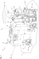
- the chassis 24 carries a machine frame 30 via lifting columns 28 that is variable in height, i.e. displaceable along the machine height axis H (see figure 2 ), which carries functional devices of the cold milling machine 10.
- the functional devices include the already mentioned working device 12 together with the milling drum box 14, the control panel 18, the hydraulic motors 25, a diesel engine 32 (see figure 2 ) as a power source within the meaning of the introduction to the description, a cooling device 34 (see figure 2 ), a cover 36, to name just a few examples of functional devices.
- the engine 32 is surrounded by an air-filled ventilation volume 32a, the air of which is heated by the engine 32 during its operation due to convection and radiation.
- the cover 36 is formed with a suction port portion 38 and a blowout port portion 40 in which the cover 36 is pierced with ports to allow passage of air between an outer side of the cover 36 and an opposite inner side.
- the cooling device 34 air from the External environment of the road cold milling machine 10 suck, which they after passage through the cooling device 34 through the openings of the blow-out opening area 40 promotes back into the external environment of the road cold milling machine 10 back.
- the suction takes place or the suction opening area 38 is located predominantly on the upper side of the cover 36 and on its right side of the machine in the forward travel direction V.
- the blowing out takes place or the blowout opening area 40 is located predominantly or even completely on the opposite side of the machine in the transverse direction Q and on the left side of the machine in the forward travel direction V.
- a bearing formation 42 carried by machine frame 30 for storing a material transport device, not shown, but present during tillage, for loading the milled material, in particular a conveyor belt .
- the cooling device 34 embodied as a preassembled air flow assembly 44 comprises a heat exchanger arrangement 46 and a fan arrangement 48 with two fans 48a and 48b arranged next to one another by way of example.
- the fan arrangement 48 can deviate from the illustrated example only have one fan or more than two fans and the plurality of fans can be arranged in other spatial relationships to one another, for example one above the other or offset diagonally to one another.
- the heat exchanger arrangement 46 has a first heat exchanger 46a, through which a cooling medium of the internal combustion engine 32 flows, in order to give off heat in the heat exchanger 46a, which it has previously absorbed in the internal combustion engine 32, to the air passing through the heat exchanger 46a.
- the heat exchanger arrangement 46 has a second heat exchanger 46b, which serves as a charge air cooler for a turbocharger 50 that cooperates with the internal combustion engine 32 .
- the cooling medium flowing through the heat exchanger 46a is liquid
- the cooling medium flowing through the heat exchanger 46b is gaseous.
- the heat exchanger assembly 46 can be more or less than those shown have two heat exchangers 46a and 46b.
- a further heat exchanger in the heat exchanger arrangement 46 can serve as a hydraulic oil cooler and the hydraulic oil flowing through the hydraulic motors 25 can flow through it as a cooling medium.
- the hydraulic motors 25 can also be cooled with the hydraulic oil.
- the two heat exchangers 46a and 46b can be arranged in a spatial relationship to one another that differs from that illustrated, ie, for example, alongside one another along the machine's longitudinal axis L instead of behind one another as illustrated.
- the heat exchanger assembly 46 may include a gas-to-liquid heat exchanger as part of a charge air cooling system, in which case the charge air transfers heat to a liquid cooling medium, which transfers the heat to the air passing through the heat exchanger assembly 46.
- first coolant line 52a conveying the liquid coolant of the internal combustion engine 32 to the heat exchanger 46a and the second coolant line 52b conveying the gaseous coolant to the heat exchanger 46b.
- the airflow assembly 44 is mounted directly on the machine frame 30 via a plurality of bearing formations 54 fixed to the machine frame, in the example shown a total of four.
- the air flow assembly 44 is supported by a total of four counter bearing formations 56, of which figure 3 only three can be seen, fixed to the bearing formations 54 of the machine frame 30.
- the abutment formations 56 are fixed to a frame 58 made of a flat material, such as sheet metal, for example by welding.
- the frame 58 supports the heat exchanger assembly 46 and also the fan assembly 48.
- the housing-like frame 58 encloses a mixing volume 60 between the heat exchanger arrangement 46 and the fan arrangement 48 with a housing section 59.
- the preassembled air flow assembly 44 has a roughly prismatic shape with an essentially triangular base area. Two lateral surfaces of the triangular prism are formed by the heat exchanger arrangement 46 on the one hand and by the fan arrangement 48 on the one hand. A third lateral surface forms an underside of the housing section 59 and thus a boundary wall of the mixing volume 60.
- a through opening 62 is formed, through which the mixing volume 60 from the outside, namely, as figure 2 shows, is accessible from the environment of the internal combustion engine 32, more precisely from the ventilation volume 32a.
- the through opening 62 is formed in a plate 64 which is mounted on the remaining end face of the housing section 59 and which covers a passage which passes through the end face of the housing section 59 which carries the plate 64 .
- a passage can be provided as a kind of original passage opening with a maximum passage cross section, which can be adapted to the respective application of the specific soil cultivation machine by arranging the plate 64 with the passage opening 62 optimized for the respective application in terms of shape, position and passage cross section.
- the through opening 62 is formed by a large number of smaller elementary openings, for example designed as the plate 64 penetrating bores, which form the through opening 62 in their entirety. Also, the through hole 62 is formed in the plate 64 closer to one corner than the other three corners in order to suck a ventilation airflow from a most optimum portion of the ventilation volume 32a around the engine 32 for this purpose.
- the through-opening 62 can be formed by a single opening or by a smaller number of openings, in deviation from the representation. It may also be formed in plate 64 at a different location.
- the two fans 48a and 48b are substantially identical and are arranged with axes of rotation Ra and Rb parallel to each other.
- the fan wheels of the fans 48a and 48b are preferably driven hydraulically or else by an electric motor, with each fan 48a and 48b preferably being able to be controlled or regulated separately from the other.
- the heat exchanger assembly 46 as a flat heat exchanger assembly substantially in a to the plane of the figure 4 orthogonal heat exchanger plane WE is arranged and that the fan assembly 48 as a flat fan assembly substantially in a plane to the drawing figure 4 also orthogonal fan level LE is arranged.
- the heat exchanger level WE and the fan level LE enclose an angle of between 100° and 110°.
- You are with respect to a plane orthogonal to the drawing figure 4 running pivot axis SA pivoted relative to each other and form a ridge F with the pivot axis SA and the machine longitudinal axis L parallel ridge line.
- the ridge F is formed by an uppermost edge of a contact frame 74 in the machine height direction H.
- the contact frame 74 surrounds a surface of the heat exchanger arrangement 46 through which the cooling air flow KL can flow for heat transfer.
- the heat exchanger level WE and the fan level LE are not infinitely thin levels in the mathematical sense but are component levels which have a significantly smaller dimension in their respective thickness direction than in their two directions of extension orthogonal to the thickness direction and to each other.
- the through hole 62' formed in the plate 64 is in figure 4 designed as a single coherent passage opening 62 ′, which, however, is covered by a panel 68 that can be displaced along two rails 66 .
- the panel 68 itself in turn has a panel opening 70 passing through it, which can be brought into an overlap with the through-opening 62' by displacing the panel 68 along the rails 66.
- the cross-section of the through-opening 62' that can be flowed through can be changed.
- the aperture 68 can be displaced by an actuator 72 between the in figure 4 shown closed position, in which the diaphragm 68 completely closes the through-opening 62' and an open position, in which the diaphragm opening 70 and the through-opening 62' completely overlap. Approaching intermediate positions is preferably possible. However, it can also be provided that the passage opening 62 ′ is only either completely opened or completely closed by moving the diaphragm 68 .
- the fan arrangement 48 is provided on the cooling device 34 or on the air flow assembly 44 in such a way that the heat exchanger arrangement 46 and the passage opening 62 or 62 ′ are located on the suction side of the fan arrangement 48 . Operation of the fan arrangement 48 therefore generates a negative pressure with respect to the ambient atmosphere on the suction side of the fan arrangement 48 , which generates a cooling air flow KL from the outside through the heat exchanger arrangement 46 into the mixing volume 60 . Likewise, when the passage opening 62 or 62' is open, the negative pressure generates a 4 orthogonal ventilation airflow LL from the outside through the passage opening 62 or 62' into the mixing volume 60, where the cooling airflow KL and the ventilation airflow LL coming from the area of the internal combustion engine 32 can mix. The one from the fan assembly 48 generated pressure difference between its suction side and its pressure side also causes an exhaust air flow AL from the mixing volume 60 out through the fan assembly 48 therethrough.
- the directions of flow of cooling air flow KL and exhaust air flow AL indicated by the associated arrows, which correspond to the respective thickness direction of the arrangement through which flow occurs, preferably lie in one plane. This is in turn preferably inclined between 75° and 105° to the machine longitudinal direction L, in particular orthogonally to it.
- the direction of flow of the ventilation air flow LL through the passage opening 62 or 62′ runs transversely to the plane spanned by the flow directions of the cooling air flow KL and the exhaust air flow AL, in particular orthogonally to this.
- a shaft wall 76 is shown in dashed lines as a separating device, which extends from the cover 36 to the heat exchanger arrangement 46 when the soil tillage machine 10 is in the operational state.
- the arrow KL in figure 4 also symbolizes a flow path along which the cooling air flow KL flows from the openings 38 in the cover 36 to the heat exchanger arrangement 46 and further through it. This flow path is located within the shaft wall 76 in a flow channel defined by the shaft wall 76 and delimited from its external environment.
- the shaft wall 76 At its longitudinal end facing the heat exchanger arrangement 46, the shaft wall 76 preferably has a counter-bearing frame 78 which, when the soil tillage implement 10 is in the operational state, can bear against the bearing frame 74 with the interposition of a gasket 80 opposite.
- the preferably elastomeric seal 80 can be firmly connected to the contact frame 76 or to the shaft wall 76, in particular to the counter-contact frame 78.
Description
Die vorliegende Erfindung betrifft eine selbstfahrende Bodenbearbeitungsmaschine, wie etwa eine Straßenfräse, insbesondere Straßenkaltfräse, einen Surface-Miner oder einen Stabilisierer. Die Bodenbearbeitungsmaschine umfasst:
- ein Fahrwerk, vermittels welchem die Bodenbearbeitungsmaschine abrollbar auf einem Untergrund aufsteht, und
- einen vom Fahrwerk getragenen Maschinenrahmen,
- eine am Maschinenrahmen aufgenommene Leistungsquelle zur Bereitstellung von Leistung, welche für einen Fahrbetrieb oder/und für einen Bodenbearbeitungsbetrieb der Bodenbearbeitungsmaschine nutzbar ist,
- eine an dem Maschinenrahmen aufgenommene Arbeitsvorrichtung zur Bodenbearbeitung,
- eine Kühlvorrichtung zur Kühlung einer Funktionsvorrichtung der Bodenbearbeitungsmaschine, wobei die Kühlvorrichtung umfasst:
- wenigstens eine Wärmetauscheranordnung, umfassend wenigstens einen Wärmetauscher, welcher zur Übertragung von Wärme von einem Kühlmedium an Luft ausgebildet ist, und
- eine Lüfteranordnung, welche einerseits dazu ausgebildet und angeordnet ist, einen die Wärmetauscheranordnung passierenden Kühl-Luftstrom zu erzeugen und welche andererseits dazu ausgebildet und angeordnet ist, im Bereich der Leistungsquelle einen von der Leistungsquelle weg strömenden
- a chassis, by means of which the soil tillage machine stands up on a subsurface so that it can be rolled, and
- a machine frame supported by the chassis,
- a power source mounted on the machine frame for providing power which can be used for driving and/or for soil tillage operation of the soil tillage machine,
- a working device for tillage mounted on the machine frame,
- a cooling device for cooling a functional device of the soil treatment machine, the cooling device comprising:
- at least one heat exchanger arrangement, comprising at least one heat exchanger, which is designed to transfer heat from a cooling medium to air, and
- a fan arrangement which is designed and arranged on the one hand to generate a cooling air flow passing through the heat exchanger arrangement and which is designed and arranged on the other hand to generate a flow of air away from the power source in the region of the power source
Lüftungs-Luftstrom zu erzeugen, wobei die Wärmetauscheranordnung und ein Lüftungsvolumen, in welchem der Lüftungs-Luftstrom von der Leistungsquelle weg strömt, auf der Saugseite der Lüfteranordnung angeordnet sind.To generate ventilation airflow, wherein the heat exchanger assembly and a ventilation volume in which the ventilation airflow flows away from the power source are arranged on the suction side of the fan assembly.
Eine solche Bodenbearbeitungsmaschine in Gestalt einer Straßenfräse ist aus der
Dabei lehrt die
Im Einzelnen lehrt die
Die erstgenannte technische Lehre hat den Nachteil, dass die durch den Wärmetauscher hindurch bewegte Luft aufgrund der beigemischten erwärmten Luft, die aus dem Bereich der Brennkraftmaschine abgesaugt wurde, eine höhere Temperatur aufweist als die angesaugte reine Frischluft, was am Wärmetauscher die Wärmeabgabe von Kühlmedium an Luft und damit dessen Effizienz reduziert.The first-mentioned technical teaching has the disadvantage that the air moving through the heat exchanger has a higher temperature than the pure fresh air sucked in due to the added heated air that was sucked out of the area of the internal combustion engine, which in the heat exchanger causes the heat transfer from cooling medium to air and thus reduces its efficiency.
Die zweitgenannte technische Lehre hat den einen Nachteil, dass drückend betriebene Lüfter weniger effizient sind als mit gleicher Leistung saugend betriebene Lüfter, und hat den weiteren Nachteil, dass auf der Druckseite insbesondere die drückend zur Brennkraftmaschine hin bewegte Luft entlang von nahezu unkontrollierbaren und unvorhersagbaren Strömungswegen strömt und an beliebigen, häufig auch nachteiligen Orten an der Bodenbearbeitungsmaschine in die Außenumgebung austritt.The second-mentioned technical teaching has the one disadvantage that fans operated by pressure are less efficient than fans operated by suction with the same power, and has the further disadvantage that on the pressure side, in particular, the air that is pushed towards the internal combustion engine flows along almost uncontrollable and unpredictable flow paths and leaks into the outside environment at any, often disadvantageous, locations on the soil tillage implement.
Aus der
Es ist daher Aufgabe der vorliegenden Erfindung, die eingangs genannte Bodenbearbeitungsmaschine unter Ausräumung der zuvor genannten Nachteile zu verbessern.It is therefore the object of the present invention to improve the soil cultivating machine mentioned at the outset while eliminating the disadvantages mentioned above.
Diese Aufgabe löst die vorliegende Erfindung an einer eingangs genannten Bodenbearbeitungsmaschine dadurch, dass das Lüftungsvolumen bezogen auf den Kühl-Luftstrom stromabwärts der Wärmetauscheranordnung angeordnet ist, so dass der durch die Lüfteranordnung erzeugte Lüftungs-Luftstrom stromabwärts der Wärmetauscheranordnung und stromaufwärts der Lüfteranordnung auf den Kühl-Luftstrom trifft.This object is achieved by the present invention on a soil cultivation machine mentioned at the outset in that the ventilation volume is arranged downstream of the heat exchanger arrangement in relation to the cooling air flow, so that the ventilation air flow generated by the fan arrangement is on the cooling air flow downstream of the heat exchanger arrangement and upstream of the fan arrangement meets.
Unter Verwendung der erfindungsgemäßen Anordnung von Wärmetauscheranordnung, Lüfteranordnung und Lüftungsvolumen wird zum einen die Lüfteranordnung saugend betrieben, was nicht nur die effektivste Betriebsart einer Lüfteranordnung ist, sondern was auch eine Möglichkeit sicherstellt, festzulegen, wohin die durch die Wärmetauscheranordnung oder/und durch die Leistungsquelle erwärmte Luft von der Bodenbearbeitungsmaschine weg abgeblasen werden kann.Using the arrangement of heat exchanger arrangement, fan arrangement and ventilation volume according to the invention, on the one hand, the fan arrangement is operated with suction, which is not only the most effective mode of operation of a fan arrangement, but also ensures a possibility of determining where the heat heated by the heat exchanger arrangement and/or by the power source goes Air can be blown away from the soil tillage implement.
Zum anderen trifft der aus dem Lüftungsvolumen der Leistungsquelle abgesaugte und von der Leistungsquelle, deren Temperatur sich im Betrieb unvermeidlich erhöht, erwärmte Lüftungs-Luftstrom erst auf den Kühl-Luftstrom, nachdem dieser die Wärmetauscheranordnung passiert hat. Dadurch wird erreicht, dass die Wärmetauscheranordnung von einem möglichst kühlen Luftstrom passiert wird, welcher aufgrund der somit höheren Temperaturdifferenz zwischen dem die Wärmetauscheranordnung durchströmenden Kühlmedium und dem passierenden Luftstrom für einen höheren konvektiven Wärmeabtransport von der Wärmetauscheranordnung sorgt als dies bei einer Beimischung eines erwärmten Lüftungs-Luftstroms der Fall wäre.On the other hand, the ventilation air flow extracted from the ventilation volume of the power source and heated by the power source, whose temperature inevitably increases during operation, only meets the cooling air flow after it has passed the heat exchanger arrangement. This ensures that the heat exchanger arrangement is passed by the coolest possible air flow, which, due to the higher temperature difference between the cooling medium flowing through the heat exchanger arrangement and the air flow passing through, ensures greater convective heat transport from the heat exchanger arrangement than when a heated ventilation air flow is mixed in the case would be.
Ebenso wird die Leistungsquelle effizient belüftet, da auch der Bereich um die Leistungsquelle herum, also das Lüftungsvolumen, welches an die Leistungsquelle wenigstens angrenzt und die Leistungsquelle bevorzugt wenigstens teilweise umgibt, nicht von Luft umströmt wird, welche zuvor durch eine Wärmeübertragung von der Wärmetauscheranordnung auf die Luft erwärmt wurde.The power source is also efficiently ventilated, since the area around the power source, i.e. the ventilation volume which is at least adjacent to the power source and preferably at least partially surrounds the power source, is not flowed around by air which had previously been caused by heat transfer from the heat exchanger arrangement to the air was heated.
Folglich kann die Wärmetauscheranordnung effektiv betrieben und kann die sich im Betrieb stets erwärmende Leistungsquelle effektiv belüftet werden.Consequently, the heat exchanger assembly can be operated effectively, and the power source, which is always heated during operation, can be ventilated effectively.
Ein weiterer Vorteil der Erfindung liegt darin, dass nur ein Teil der gesamten von der Lüfteranordnung geförderten Luftmenge aus dem Lüftungsvolumen nahe der Leistungsquelle angesaugt wird, wodurch der Unterdruck in der Umgebung der Leistungsquelle und damit der Eintrag von Schmutz in diese Umgebung gegenüber dem Stand der Technik gemäß
Bevorzugt ist der Ausgangspunkt sowohl des Kühl-Luftstroms als auch des Lüftungs-Luftstroms die Außenumgebung und damit die Umgebungsatmosphäre der Bodenbearbeitungsmaschine, ohne dass einer der Luftströme vor dem Erreichen der Wärmetauscheranordnung oder der Leistungsquelle konvektiv Wärme von einer anderen Funktionsvorrichtung aufnimmt. Allenfalls strömt durch die Lüfteranordnung angesaugte Luft durch eine Abdeckung der Wärmetauscheranordnung oder/und eine Abdeckung der Leistungsquelle von der Außenumgebung zur Wärmetauscheranordnung bzw. zur Leistungsquelle hin.The starting point of both the cooling air flow and the ventilation air flow is preferably the outside environment and thus the ambient atmosphere of the soil treatment machine, without one of the air flows convectively absorbing heat from another functional device before reaching the heat exchanger arrangement or the power source. At most, air sucked in by the fan arrangement flows through a cover of the heat exchanger arrangement and/or a cover of the power source from the outside environment to the heat exchanger arrangement or to the power source.
Die Leistungsquelle ist bevorzugt eine Brennkraftmaschine, wobei als Brennkraftmaschine wiederum eine Diesel-Brennkraftmaschine bevorzugt ist. Diesel-Brennkraftmaschinen können stationär mit gutem Wirkungsgrad und niedrigen Emissionen betrieben werden. Es soll jedoch nicht ausgeschlossen sein, dass ein Ottomotor oder eine andere Art von thermischer oder elektrischer Kraftmaschine als Leistungsquelle verwendet wird oder dass die Leistungsquelle eine oder mehrere Brennstoffzellen umfasst. Die Leistungsquelle kann insbesondere eine Brennkraftmaschine mit Turbolader sein. Die Leistungsquelle ist gleichsam ein von der Bodenbearbeitungsmaschine mitgeführtes Kraftwerk, welches für den Betrieb der Bodenbearbeitungsmaschine erforderliche Leistung bereitstellt. Im Falle einer thermischen Kraftmaschine als Leistungsquelle kann die Bodenbearbeitungsmaschine in an sich bekannter Weise einen oder mehrere Leistungswandler umfassen, welche die von der Leistungsquelle in einer Form bereitgestellte Leistung in eine in anderer Form bereitgestellte Leistung umwandeln. So kann beispielsweise die Arbeitsvorrichtung zur Bodenbearbeitung von einem mechanischen Ausgabeglied der Leistungsquelle, wie einer Kurbelwelle, unter Zwischenschaltung von Getrieben mechanisch angetrieben werden. Ebenso kann, beispielsweise über eine Nebenabtriebswelle eines solchen Getriebes, insbesondere eines Pumpenverteilergetriebes, eine Hydraulikpumpe betrieben werden, welche die von der Leistungsquelle bereitgestellte Leistung in potentielle Energie in Form eines erhöhten Druckniveaus eines Hydrauliköls wandelt. Weiterhin kann Leistung der Leistungsquelle über einen Generator von mechanischer Leistung in elektrische Leistung umgewandelt werden.The power source is preferably an internal combustion engine, with a diesel internal combustion engine being preferred as the internal combustion engine. Diesel internal combustion engines can be operated stationary with good efficiency and low emissions. However, it is not intended to exclude that a spark ignition engine or other type of thermal or electric prime mover is used as the power source or that the power source includes one or more fuel cells. In particular, the power source can be a turbocharged internal combustion engine. The power source is, so to speak, a power plant carried along by the soil tillage machine, which provides the power required for the operation of the soil tillage machine. In the case of a thermal engine as the power source, the soil treatment machine can, in a manner known per se, comprise one or more power converters, which convert the power provided by the power source in one form into power provided in another form. For example, the working device for tillage of a mechanical output member of the power source, such as a crankshaft, are mechanically driven with the interposition of gears. A hydraulic pump, which converts the power provided by the power source into potential energy in the form of an increased pressure level of a hydraulic oil, can also be operated, for example via an auxiliary output shaft of such a transmission, in particular a pump transfer case. Furthermore, power from the power source can be converted from mechanical power into electrical power via a generator.
Gemäß einer stärker verallgemeinerten Lehre der vorliegenden Erfindung kann anstelle der Leistungsquelle eine gesondert von der Wärmetauscheranordnung, und bevorzugt mit Abstand von dieser, eine Wärmequelle angeordnet sein, von welcher wegführend die Lüfteranordnung im Betrieb einen Lüftungs-Luftstrom erzeugt, um die Wärmequelle zu belüften. Es gilt für die Wärmequelle, die beispielsweise eine elektrische Energiespeicheranordnung oder ein Getriebe sein kann, das in vorliegender Anmeldung zur Leistungsquelle Gesagte.In accordance with a more general teaching of the present invention, instead of the power source, a heat source may be disposed separate from, and preferably spaced from, the heat exchanger assembly, leading away from which the fan assembly generates a ventilation airflow in operation to ventilate the heat source. For the heat source, which can be an electrical energy storage arrangement or a transmission, for example, what was said in the present application for the power source applies.
Die Arbeitsvorrichtung zur Bodenbearbeitung ist bevorzugt eine bodenabtragende Arbeitsvorrichtung. Dabei ist bevorzugt an eine rotierende Arbeitsvorrichtung mit geometrisch bestimmten Schneiden, wie etwa an eine Fräswalze, oder/und mit geometrisch unbestimmte Schneiden, wie beispielsweise an eine sogenannte "Grinding-Walze" zur gezielten Texturierung von Bodenoberflächen gedacht.The working device for tilling the soil is preferably a soil-removing working device. A rotating working device with geometrically defined cutting edges, such as a milling drum, and/or with geometrically undefined cutting edges, such as a so-called "grinding roller" for targeted texturing of soil surfaces, is preferred.
Ein "Passieren" der Wärmetauscheranordnung durch den Kühl-Luftstrom bezeichnet vorliegend jede Art von Strömung des Kühl-Luftstroms an der Wärmetauscheranordnung vorbei unter konvektiver Abführung von Wärme von der Wärmetauscheranordnung durch den Kühl-Luftstrom. Beim Passieren der Wärmetauscheranordnung kann der Kühl-Luftstrom im Gleich- oder Gegenstrom entlang einer Wärmeübertragungsfläche der Wärmetauscheranordnung bezogen auf die Strömungsrichtung eines auf der anderen Seite der Wärmeübertragungsfläche strömenden Kühlmediums gleichgerichtet bzw. entgegengesetzt gerichtet strömen. Bevorzugt ist die Wärmetauscheranordnung eine Kreuzstrom-Wärmetauscheranordnung, bei welcher der Kühl-Luftstrom quer zur Strömungsrichtung des die Wärmetauscheranordnung durchströmenden Kühlmediums strömt. Die Wärmetauscheranordnung kann den Kühl-Luftstrom führende Kühlkanäle zur Durchströmung mit dem Kühl-Luftstrom aufweisen.A "passing" of the heat exchanger arrangement by the cooling air flow refers to any type of flow of the cooling air flow past the heat exchanger arrangement with convective removal of heat from the heat exchanger arrangement by the cooling air flow. When passing through the heat exchanger arrangement, the cooling air flow can flow co-currently or countercurrently along a heat transfer surface of the heat exchanger arrangement in the same or opposite direction to the flow direction of a cooling medium flowing on the other side of the heat transfer surface. The heat exchanger arrangement is preferably a cross-flow heat exchanger arrangement, in which the cooling air flow is transverse to the flow direction of the heat exchanger arrangement Cooling medium flows. The heat exchanger arrangement can have cooling ducts guiding the cooling air flow through which the cooling air flow can flow.
Grundsätzlich kann daran gedacht sein, dass der Kühl-Luftstrom einerseits und der Lüftungs-Luftstrom andererseits getrennt voneinander durch die Lüfteranordnung angesaugt und nach Durchgang durch die Lüfteranordnung in die Außenumgebung abgeblasen werden. Allerdings erfordert eine konsequente Trennung der beiden Luftströme die Einrichtung entsprechender Strömungskanäle, was einen erhöhten Aufwand darstellt und was zu einer komplizierten Strömungsführung führt, wenn stets die gesamte Wärmetauscheranordnung für den Kühl-Luftstrom durchströmbar sein soll. Erhöhter Aufwand und erhöhte Komplexität erhöhen die Störungsanfälligkeit. Bevorzugt ist daher, dass zwischen der Wärmetauscheranordnung und der Lüfteranordnung ein Mischvolumen vorgesehen ist, in welchem sich der Kühl-Luftstrom und der Lüftungs-Luftstrom vermischen. Zu dem Zeitpunkt, zu dem sich der Kühl-Luftstrom und der Lüftungs-Luftstrom vermischen, haben Sie als konvektive Luftströme ihre Aufgabe der Wärmeabführung bereits erfüllt und können, ohne Beeinträchtigungen von Wirkungsgraden befürchten zu müssen, gemeinsam und vermischt als Abluft durch die Lüfteranordnung hindurch auf deren Druckseite gefördert und bevorzugt in die Außenumgebung abgeblasen werden.In principle, it can be considered that the cooling airflow on the one hand and the ventilation airflow on the other hand are sucked in separately from one another by the fan arrangement and blown off into the outside environment after passing through the fan arrangement. However, a consistent separation of the two air flows requires the establishment of corresponding flow channels, which represents an increased effort and leads to a complicated flow control if the entire heat exchanger arrangement is to be able to flow through the entire heat exchanger arrangement for the cooling air flow. Increased effort and increased complexity increase the susceptibility to failure. It is therefore preferred that a mixing volume is provided between the heat exchanger arrangement and the fan arrangement, in which volume the cooling air flow and the ventilation air flow mix. By the time the cooling airflow and ventilation airflow mix, they have already done their job of dissipating heat as convective airflows and can flow together and mix as exhaust air through the fan assembly without having to fear any impact on efficiency whose pressure side are conveyed and preferably blown off into the outside environment.
Es kann daran gedacht sein, die Abluft stromaufwärts oder stromabwärts der Lüfteranordnung zu filtern, also im Strömungsweg der Abluft einen von der Abluft durchströmten Luftfilter anzuordnen. Da in der Regel nur Luft aus der Außenumgebung angesaugt und als Kühl-Luftstrom den Wärmetauscher passierend gefördert wird bzw. nur Luft aus dem Bereich der Leistungsquelle abgesaugt wird, für welche in der Regel Luft aus der Außenumgebung nachströmt, hält sich der Verschmutzungsgrad der beiden Luftströme in Grenzen, sodass weder zum Schutz der ohnehin robusten Lüfteranordnung noch zur Reinigung der Abluft eine Filterung der Luftströme nötig ist.It can be considered to filter the exhaust air upstream or downstream of the fan arrangement, ie to arrange an air filter through which the exhaust air flows in the flow path of the exhaust air. Since, as a rule, only air is sucked in from the outside environment and conveyed as a cooling air flow passing the heat exchanger or only air is sucked out of the area of the power source, for which air from the outside environment usually flows, the degree of contamination of the two air flows is maintained within limits, so that there is no need to filter the air flows either to protect the already robust fan arrangement or to clean the exhaust air.
Zu Erleichterung der Montage der Bodenbearbeitungsmaschine kann die Bodenbearbeitungsmaschine, insbesondere deren Kühlvorrichtung, eine vormontierte Luftstrom-Baugruppe aufweisen, wobei die Luftstrom-Baugruppe die Lüfteranordnung, die Wärmetauscheranordnung und einen die Lüfteranordnung und die Wärmetauscheranordnung tragenden Rahmen aufweist. Die Luftstrom-Baugruppe kann so einfach an einem gesonderten Montageplatz vormontiert und als vormontierte Baugruppe an der Bodenbearbeitungsmaschine, insbesondere an deren Maschinenrahmen, befestigt werden.To facilitate the assembly of the floor-working machine, the floor-working machine, in particular its cooling device, can have a pre-assembled air flow assembly, the air flow assembly including the fan arrangement, the heat exchanger arrangement and a frame supporting the fan assembly and the heat exchanger assembly. The air flow subassembly can thus be easily preassembled at a separate assembly station and fastened as a preassembled subassembly to the soil tillage machine, in particular to its machine frame.
Der Rahmen kann ein Fachwerkrahmen mit einer Mehrzahl von Stäben sein, an welchen die Lüfteranordnung und die Wärmetauscheranordnung gehaltert sind. Ein skelettartiger Fachwerkrahmen weist ein verhältnismäßig geringes Gewicht auf. Um definierte Strömungsbedingungen zu erzwingen, kann der Rahmen einen das Mischvolumen wenigstens teilweise einfassenden Gehäuseabschnitt aufweisen. Der Rahmen kann hierzu eine Rahmenhaut aufweisen und zu diesem Zweck beispielsweise wenigstens abschnittsweise aus Blech oder/und Kunststoffflächen gebaut oder/und geformt sein. So kann sichergestellt sein, dass von der Lüfteranordnung tatsächlich nur oder weitaus überwiegend der die Wärmetauscheranordnung passierende Kühl-Luftstrom und der von der Leistungsquelle abgezogene Lüftungs-Luftstrom, jedoch keine Falschluft aus anderen Bereichen der Bodenbearbeitungsmaschine angesaugt wird. So kann verhindert werden, dass die Lüfteranordnung Luft aus Bereichen der Bodenbearbeitungsmaschine ansaugt, die keine konvektive Kühlung oder/und keine Entlüftung benötigen.The frame may be a truss frame having a plurality of rods to which the fan assembly and the heat exchanger assembly are supported. A skeletal truss frame is relatively light in weight. In order to enforce defined flow conditions, the frame can have a housing section that at least partially encloses the mixing volume. For this purpose, the frame can have a frame skin and for this purpose, for example, be built and/or formed at least in sections from sheet metal and/or plastic surfaces. In this way it can be ensured that the fan arrangement actually sucks in only or predominantly the cooling air flow passing the heat exchanger arrangement and the ventilation air flow drawn off from the power source, but no false air from other areas of the soil treatment machine. It can thus be prevented that the fan arrangement sucks in air from areas of the soil treatment machine that do not require convective cooling and/or ventilation.
Damit der Kühl-Luftstrom und der Lüftungs-Luftstrom stromaufwärts der Lüfteranordnung, aber stromabwärts der Wärmetauscheranordnung aufeinandertreffen und sich bevorzugt vermischen können, ist es vorteilhaft, wenn die Lüfteranordnung mit Abstand von der Wärmetauscheranordnung angeordnet ist. Eine besonders gute Raumausnutzung ergibt sich dann, wenn die Lüfteranordnung und die Wärmetauscheranordnung relativ zueinander um eine Schwenkachse rotatorisch verlagert sind. Dann haben unterschiedliche Bereiche der Lüfteranordnung einerseits und der Wärmetauscheranordnung andererseits unterschiedliche Abstände voneinander. Dafür sind die Strömungswege von der Wärmetauscheranordnung zur Lüfteranordnung kurz. Zusätzlich oder alternativ können die Lüfteranordnung und die Wärmetauscheranordnung längs einer Verlagerungsachse translatorisch verlagert angeordnet sein. Die translatorische Verlagerung von Wärmetauscheranordnung und Lüfteranordnung erfordert jedoch in der Regel mehr Einbauraum als eine rotatorische Verlagerung.So that the cooling air flow and the ventilation air flow can meet and preferably mix upstream of the fan arrangement but downstream of the heat exchanger arrangement, it is advantageous if the fan arrangement is arranged at a distance from the heat exchanger arrangement. A particularly good use of space results when the fan arrangement and the heat exchanger arrangement are rotationally displaced relative to one another about a pivot axis. Then different areas of the fan arrangement on the one hand and the heat exchanger arrangement on the other hand have different distances from each other. For the flow paths from the heat exchanger assembly to the fan assembly are short. Additionally or alternatively, the fan arrangement and the heat exchanger arrangement can be arranged translationally displaced along a displacement axis. However, the translatory displacement of the heat exchanger arrangement and the fan arrangement generally requires more installation space than a rotary displacement.
Zur vorteilhaften Verringerung des Bedarfs an Einbauraum ist die Lüfteranordnung bevorzugt eine im Wesentlichen ebene Lüfteranordnung. Dabei ist "eben" nicht streng mathematisch zu verstehen, sondern derart, dass die Lüfteranordnung in zwei zueinander orthogonalen Raumrichtungen erheblich größere Abmessungen aufweist als in einer zu den genannten Raumrichtungen orthogonalen dritten Raumrichtung, welche besonders bevorzugt die Durchströmungsrichtung der Lüfteranordnung ist, längs welcher die Abluft die Lüfteranordnung durchströmt. Längs der dritten Raumrichtung verläuft bevorzugt eine Rotationsachse wenigstens eines Lüfters der Lüfteranordnung, vorzugsweise, falls die Lüfteranordnung mehrere Lüfter umfasst, alle Rotationsachsen der mehreren Lüfter. Alternativ oder bevorzugt zusätzlich ist auch die Wärmetauscheranordnung eine im Wesentlichen ebene Wärmetauscheranordnung. Auch dies bedeutet, dass die Wärmetauscheranordnung längs zweier zueinander orthogonalen Raumrichtungen jeweils eine wesentlich größere Abmessung aufweist als in einer zu den beiden Raumrichtungen orthogonalen dritten Raumrichtung, welche bevorzugt eine Durchströmungsrichtung ist, längs welcher der Kühl-Luftstrom die bevorzugt als Kreuzstrom-Wärmetauscheranordnung ausgebildete Wärmetauscheranordnung durchströmt.In order to advantageously reduce the need for installation space, the fan arrangement is preferably a substantially planar fan arrangement. "Even" is not to be understood strictly mathematically, but in such a way that the fan arrangement has significantly larger dimensions in two mutually orthogonal spatial directions than in a third spatial direction orthogonal to the named spatial directions, which is particularly preferably the flow direction of the fan arrangement along which the exhaust air flows through the fan assembly. An axis of rotation of at least one fan of the fan arrangement preferably runs along the third spatial direction, preferably, if the fan arrangement comprises a plurality of fans, all axes of rotation of the plurality of fans. Alternatively or preferably additionally, the heat exchanger arrangement is also an essentially planar heat exchanger arrangement. This also means that the heat exchanger arrangement has a significantly larger dimension along two mutually orthogonal spatial directions than in a third spatial direction orthogonal to the two spatial directions, which is preferably a flow direction along which the cooling air flow flows through the heat exchanger arrangement, which is preferably designed as a cross-flow heat exchanger arrangement .
Dann, wenn sowohl die Wärmetauscheranordnung als auch die Lüfteranordnung jeweils als ebene Anordnungen ausgebildet sind, verläuft bevorzugt die Schwenkachse, um welche die beiden Anordnungen relativ zueinander rotatorisch verlagert sind, parallel zu jeder Ausbildungsebene der beiden Anordnungen.When both the heat exchanger arrangement and the fan arrangement are each designed as planar arrangements, the pivot axis about which the two arrangements are rotationally displaced relative to one another preferably runs parallel to each design plane of the two arrangements.
Die durchströmbare Fläche der Wärmetauscheranordnung ist vorzugsweise größer als die durchströmbare Fläche der Lüfteranordnung, sodass an der Wärmetauscheranordnung eine möglichst große Wärmeübertragungsfläche bereitgestellt sein kann. Die durchströmbare Fläche eines Lüfters der Lüfteranordnung ist bevorzugt kreisförmig oder ringförmig, damit sich diese möglichst eng an ein rotierendes Lüfterrad an nähern kann. Falls die Lüfteranordnung mehrere Lüfter aufweist, ist bevorzugt jede durchströmbare Fläche eines Lüfters kreisförmig oder ringförmig.The area of the heat exchanger arrangement through which flow can take place is preferably larger than the area of the fan arrangement through which flow can take place, so that the largest possible heat transfer area can be provided on the heat exchanger arrangement. The surface of a fan of the fan arrangement through which air can flow is preferably circular or ring-shaped, so that it can approach a rotating fan wheel as closely as possible. If the fan arrangement has a plurality of fans, each surface of a fan through which air can flow is preferably circular or ring-shaped.
Zur möglichst guten Ausnutzung des zur Anbringung der Wärmetauscheranordnung bereitgestellten Einbauraums ist die durchströmbare Fläche der Wärmetauscheranordnung bevorzugt rechteckig.For the best possible utilization of the installation space provided for attaching the heat exchanger arrangement, the flow-through surface of the heat exchanger arrangement is preferably rectangular.
Dann, wenn die Lüfteranordnung und die Wärmetauscheranordnung um die Schwenkachse relativ zueinander rotatorisch verlagert sind, beträgt bevorzugt der rotatorische Verlagerungswinkel zwischen 65° und 115°, besonders bevorzugt zwischen 80° und 100°. Durch diese Abwinkelung der beiden Anordnungen relativ zueinander um einen Verlagerungswinkel in einem Winkelbereich um einen rechten Winkel herum können über einer verhältnismäßig geringen Grundfläche dennoch eine Wärmetauscheranordnung und eine Lüfteranordnung mit jeweils verhältnismäßig großen durchströmbaren Flächen angeordnet werden. Die oben genannte Luftstrom-Baugruppe kann dann eine grob prismatische Form aufweisen, beispielsweise mit einem Mischvolumen mit im Wesentlichen dreieckiger Grundform, wobei das Mischvolumen längs einer Seite durch die Lüfteranordnung, längs einer zweiten Seite durch die Wärmetauscheranordnung und längs einer dritten Seite durch eine Wand des den Gehäuseabschnitt ausbildenden Rahmens gebildet sein kann.When the fan arrangement and the heat exchanger arrangement are rotationally displaced relative to each other about the pivot axis, the rotational displacement angle is preferably between 65° and 115°, particularly preferably between 80° and 100°. This angling of the two arrangements relative to one another by a displacement angle in an angular range around a right angle allows a heat exchanger arrangement and a fan arrangement, each with relatively large flow-through surfaces, to be arranged over a relatively small base area. The above-mentioned air flow assembly can then have a roughly prismatic shape, for example with a mixing volume with a substantially triangular basic shape, the mixing volume being formed along one side by the fan arrangement, along a second side by the heat exchanger arrangement and along a third side by a wall of the the frame forming the housing portion may be formed.
Die Lüfteranordnung und die Wärmetauscheranordnung können dann räumlich sehr kompakt, insbesondere als sehr kompakte Luftstrom-Baugruppe, an der Bodenbearbeitungsmaschine angeordnet werden, wenn der Lüftungs-Luftstrom quer zur Strömungsrichtung des die Wärmetauscheranordnung passierenden Kühl-Luftstroms oder/und quer zu einem die Lüfteranordnung durchströmenden Abluftstrom zum Mischvolumen hin strömt. Im Falle der oben beispielhaft genannten grob prismatischen Luftstrom-Baugruppe können somit zwei Luftströme, bevorzugt der Kühl-Luftstrom und der Abluftstrom, durch die Mantelfläche der grob prismatischen Luftstrom-Baugruppe strömen und kann ein Luftstrom, bevorzugt der Lüftungs-Luftstrom, durch eine Stirnfläche der grob prismatischen Luftstrom-Baugruppe strömen.The fan arrangement and the heat exchanger arrangement can then be arranged spatially in a very compact manner, in particular as a very compact air flow assembly, on the soil tillage machine if the ventilation air flow is transverse to the direction of flow of the cooling air flow passing through the heat exchanger arrangement and/or transverse to an exhaust air flow flowing through the fan arrangement flows towards the mixing volume. In the case of the roughly prismatic airflow assembly mentioned above as an example, two airflows, preferably the cooling airflow and the exhaust airflow, can flow through the lateral surface of the roughly prismatic airflow assembly and one airflow, preferably the ventilation airflow, can flow through an end face of the flow roughly prismatic airflow assembly.
Beispielsweise kann der das Mischvolumen wenigstens teilweise einfassende Gehäuseabschnitt des Rahmens eine mit Abstand sowohl von der Wärmetauscheranordnung als auch von der Lüfteranordnung gelegene Durchgangsöffnung aufweisen, welche vom Lüftungs-Luftstrom durchströmbar ist. Wie zuvor dargelegt wurde, ist bevorzugt der die Durchgangsöffnung aufweisende Gehäuseabschnitt Teil einer Stirnwand einer prismatischen Luftstrom-Baugruppe.For example, the housing section of the frame at least partially enclosing the mixing volume can have a passage opening located at a distance from both the heat exchanger arrangement and the fan arrangement, through which the ventilation air flow can flow. As previously stated, is preferred the housing section having the passage opening is part of an end wall of a prismatic air flow assembly.
Grundsätzlich kann diese Durchgangsöffnung einen unveränderlichen Querschnitt aufweisen, dessen Gestalt oder/und Größe oder/und Lage durch entsprechende Versuche optimiert werden kann bzw. können. Es kann jedoch auch daran gedacht sein, zur Anpassung der Belüftung der Leistungsquelle, beispielsweise abhängig von ihrem Betriebszustand, eine vom Lüftungs-Luftstrom durchströmbare Querschnittsfläche der Durchgangsöffnung zur Veränderung der unter gegebenen Betriebsbedingungen pro Zeiteinheit im Lüftungs-Luftstrom strömenden Lüftungs-Luftmenge veränderbar auszugestalten. Hierzu kann beispielsweise die Durchgangsöffnung eine Blendenvorrichtung aufweisen, mit welcher durch Verlagerung eines Blendenbauteils relativ zu einem die Durchgangsöffnung ausbildenden Bauteil eine Überdeckung der Durchgangsöffnung durch das Blendenbauteils aktuatorisch veränderbar ist. Wenn die Durchgangsöffnung an einem Gehäuseabschnitt des Rahmens der Luftstrom-Baugruppe ausgebildet ist, ist bevorzugt auch die Blendenvorrichtung, insbesondere das relativ zur Durchgangsöffnung bewegliche Blendenbauteil, an dem Rahmen, insbesondere an dem Gehäuseabschnitt des Rahmens, der Luftstrom-Baugruppe aufgenommen.In principle, this passage opening can have a constant cross-section, the shape and/or size and/or position of which can be optimized by appropriate tests. However, in order to adapt the ventilation of the power source, for example depending on its operating state, it can also be considered that a cross-sectional area of the through-opening through which the ventilation air flow can flow can be configured to change the amount of ventilation air flowing in the ventilation air flow per unit of time under given operating conditions. For this purpose, for example, the through-opening can have a screen device with which, by shifting a screen component relative to a component forming the through-opening, a covering of the through-opening by the screen component can be altered by actuators. If the through-opening is formed on a housing section of the frame of the airflow assembly, the panel device, in particular the panel component movable relative to the through-opening, is preferably also accommodated on the frame, in particular on the housing section of the frame, of the airflow assembly.
Im Betrieb der Bodenbearbeitungsmaschine ist in der Regel die pro Zeiteinheit benötigte Kühl-Luftmenge größer, sogar häufig deutlich größer, als die in derselben Zeiteinheit benötigte Lüftungs-Luftmenge. Ein Großteil der von der Lüfteranordnung geförderten Luftmenge strömt also durch die Wärmetauscheranordnung. Der Lüftungs-Luftstrom dient zumeist nur der Belüftung der Leistungsquelle, um in deren Umgebung einen Wärmestau zu vermeiden. Der Kühl-Luftstrom dient dagegen in der Regel der gezielten Abführung einer Wärmemenge, um während des Betriebs der Bodenbearbeitungsmaschine in der durch die Wärmetauscheranordnung gekühlten wenigstens einen Funktionsvorrichtung ein thermisches Gleichgewicht aufrecht zu erhalten.During operation of the soil treatment machine, the amount of cooling air required per unit of time is generally greater, often even significantly greater than the amount of ventilation air required in the same unit of time. A large part of the quantity of air conveyed by the fan arrangement therefore flows through the heat exchanger arrangement. The ventilation air flow mostly only serves to ventilate the power source in order to avoid heat build-up in its surroundings. The cooling air flow, on the other hand, is generally used for the targeted dissipation of a quantity of heat in order to maintain thermal equilibrium during operation of the soil treatment machine in the at least one functional device cooled by the heat exchanger arrangement.
Die Wärmetauscheranordnung kann eine Mehrzahl von Wärmetauschern aufweisen, welche bevorzugt Bestandteile unterschiedlicher Kühlkreisläufe oder/und Kühldurchläufe zur Kühlung von Funktionsvorrichtungen an der Bodenbearbeitungsmaschine sind. Dann kann vorteilhaft das jeweilige Kühlmedium unterschiedlicher Kühlkreisläufe oder/und Kühldurchläufe an ein und demselben Ort konvektiv gekühlt werden. Beispielsweise kann ein Kühlkreislauf zwischen einem Wärmetauscher und der Leistungsquelle verlaufen, ein Kühlkreislauf kann zwischen einem Wärmetauscher und einem Hydrauliköltank verlaufen oder ein Wärmetauscher kann als Ölkühler von Hydrauliköl als dem Wärme abgebenden Kühlmedium durchströmt werden. In einem Kühldurchlauf kann ein Wärmetauscher als Gas-Gas-Ladeluftkühler eines Turboladers dienen. In einem Kühlkreislauf kann ein Wärmetauscher Teil eines Gas-Flüssigkeit-Ladeluftkühlers eines Turboladers sein. Ebenso kann ein Wärmetauscher in einem Kühlkreislauf ein Getriebeölkühler sein. Unterschiedliche Wärmetauscher können also durch unterschiedliche Kühlmedien durchströmt sein. Zwei oder mehr Wärmetauscher können auch vom gleichen Kühlmedium durchströmt sein, welches jedoch in voneinander gesonderten Kühlkreisläufen umläuft oder/und in voneinander gesonderten Kühldurchläufen durchläuft.The heat exchanger arrangement can have a plurality of heat exchangers, which are preferably components of different cooling circuits and/or cooling passages for cooling functional devices on the soil treatment machine. The respective cooling medium can then advantageously be used in different cooling circuits or/and cooling passes are convectively cooled at one and the same place. For example, a cooling circuit can run between a heat exchanger and the power source, a cooling circuit can run between a heat exchanger and a hydraulic oil tank, or hydraulic oil as the heat-emitting cooling medium can flow through a heat exchanger as an oil cooler. In a cooling cycle, a heat exchanger can serve as a gas-to-gas charge air cooler of a turbocharger. In a cooling circuit, a heat exchanger may be part of a gas-to-liquid charge air cooler of a turbocharger. A heat exchanger in a cooling circuit can also be a transmission oil cooler. Different cooling media can therefore flow through different heat exchangers. Two or more heat exchangers can also have the same cooling medium flowing through them, which, however, circulates in cooling circuits that are separate from one another and/or runs through cooling passages that are separate from one another.
Ebenso kann die Lüfteranordnung eine Mehrzahl von Lüftern aufweisen, um gegebenenfalls unterschiedlich starke Luftströme in unterschiedlichen Bereichen der Lüfteranordnung und insbesondere des Mischvolumens zu erzeugen. Dies kann dann von Vorteil sein, wenn ein Wärmetauscher aus einer Mehrzahl von Wärmetauschern eine höhere konvektive Kühlleistung benötigt als andere Wärmetauscher der Wärmetauscheranordnung. Bevorzugt sind die Lüfter der Lüfteranordnung gesondert voneinander steuerbar, sodass gleichzeitig mengenmäßig unterschiedliche Luftströme durch die einzelnen Lüfter erzeugt werden können.The fan arrangement can also have a plurality of fans in order to generate air flows of different strengths in different areas of the fan arrangement and in particular in the mixing volume. This can be advantageous when one heat exchanger from a plurality of heat exchangers requires a higher convective cooling capacity than other heat exchangers in the heat exchanger arrangement. The fans of the fan arrangement can preferably be controlled separately from one another, so that the individual fans can simultaneously generate air flows that differ in terms of quantity.
Die Bodenbearbeitungsmaschine weist bevorzugt einen Fahrstand auf, von welchem aus der Betrieb der Bodenbearbeitungsmaschine gesteuert werden kann, und zwar unabhängig davon, ob es sich um einen überwiegenden Fahrbetrieb ohne Bodenbearbeitung oder um einen überwiegenden Bearbeitungsbetrieb mit nur geringer Fahrleistung handelt. Die Wärmetauscheranordnung und die Lüfteranordnung können dann zwischen dem Fahrstand und dem vorderen Längsende der Bodenbearbeitungsmaschine angeordnet sein, sodass die vorstehend beschriebene vorteilhafte Kühlvorrichtung auch an Kompaktfräsen eingesetzt werden kann, deren als Fräswalze ausgebildete Arbeitsvorrichtung im Bereich des Hecks der Bodenbearbeitungsmaschine, insbesondere unter oder/und hinter dem Fahrstand angeordnet ist.The soil cultivating machine preferably has a control station from which the operation of the soil cultivating machine can be controlled, regardless of whether it is predominantly driving without soil tillage or predominantly tilling with only low mileage. The heat exchanger arrangement and the fan arrangement can then be arranged between the control station and the front longitudinal end of the soil tillage machine, so that the advantageous cooling device described above can also be used on compact milling machines whose working device designed as a milling drum is in the area of the rear of the soil tillage machine, in particular below and/or behind is arranged at the driver's station.
Grundsätzlich kann daran gedacht sein, eine den Lüftungs-Luftstrom führende Lüftungsleitung von der Leistungsquelle zur Kühlvorrichtung zu verlegen. Eine solche Lüftungsleitung definiert dann einen Teil des Lüftungsvolumens. Dies bedeutet jedoch in der Regel eine Erhöhung des Strömungswiderstands für den Lüftungs-Luftstrom und einen zusätzlichen Montageaufwand. Bevorzugt sind daher die Wärmetauscheranordnung und die Lüfteranordnung der Leistungsquelle unmittelbar benachbart angeordnet. Besonders bevorzugt befindet sich zwischen der Leistungsquelle und der Kühlvorrichtung, insbesondere der Luftstrom-Baugruppe, keine weitere Funktionsvorrichtung, sodass die Lüfteranordnung Luft unmittelbar dem Lüftungsvolumen als Lüftungs-Luftstrom ansaugen kann. Gemäß dieser bevorzugten Ausgestaltung kann das Lüftungsvolumen ohne Ausbildung einer kanalförmigen Leitung einerseits an die Leistungsquelle angrenzen und diese sogar wenigstens teilweise umgeben, und kann das Lüftungsvolumen anderseits an die Durchgangsöffnung zum Mischvolumen angrenzen.In principle, it can be considered to lay a ventilation line that carries the ventilation air flow from the power source to the cooling device. Such a ventilation line then defines part of the ventilation volume. However, this usually means an increase in the flow resistance for the ventilation air flow and additional installation work. The heat exchanger arrangement and the fan arrangement are therefore preferably arranged directly adjacent to the power source. Particularly preferably, there is no further functional device between the power source and the cooling device, in particular the air flow assembly, so that the fan arrangement can suck in air directly from the ventilation volume as a ventilation air flow. According to this preferred embodiment, the ventilation volume can border on the power source and even at least partially surround it without forming a channel-shaped line, and the ventilation volume can also border on the passage opening to the mixing volume.
Zur Vermeidung von Beeinträchtigungen des Maschinenführers auf einem in Vorwärtsfahrtrichtung der Leistungsquelle nacheilenden Fahrstand ist bevorzugt, dass die Wärmetauscheranordnung in Maschinenquerrichtung näher bei einer Seite der Bodenbearbeitungsmaschine gelegen ist und dass die Lüfteranordnung näher bei der in Maschinenquerrichtung entgegengesetzten anderen Seite gelegen. Dadurch kann insbesondere ein Abluft-Luftstrom mit einer Strömungskomponente in Maschinenquerrichtung seitlich von der Bodenbearbeitungsmaschine abgeblasen werden. Der Fahrstand durchfährt dann bei Vorwärtsfahrt den Abluft-Luftstrom nicht.In order to avoid inconvenience to the machine operator on a control station that lags behind the power source in the forward direction of travel, it is preferred that the heat exchanger arrangement is located closer to one side of the soil tillage implement in the cross-machine direction and that the fan arrangement is located closer to the opposite side in the cross-machine direction. As a result, in particular, an exhaust air flow with a flow component in the transverse machine direction can be blown off the side of the floor working machine. When driving forward, the operator's stand does not pass through the exhaust air flow.
Der Fahrstand ist zur besseren Beobachtbarkeit der Bodenbearbeitung bevorzugt seitlich, also in Maschinenquerrichtung, zur Mittellängsachse der Maschine versetzt angeordnet. Zur Vermeidung einer Belastung des Fahrstands mit dem Abluft-Strom befindet sich dessen Abblasort bevorzugt näher bei, besonders bevorzugt an jener der beiden Seiten der Bodenbearbeitungsmaschine, von welcher der Fahrstand weg versetzt angeordnet ist. Mit anderen Worten: bevorzugt befindet sich der Abblasort näher bei, insbesondere an jener der beiden Seiten der Bodenbearbeitungsmaschine, von welcher der Fahrstand weiter entfernt ist.The operator's station is preferably arranged laterally, i.e. in the transverse direction of the machine, offset to the central longitudinal axis of the machine so that the tillage can be better observed. In order to avoid loading the operator's stand with the exhaust air flow, its discharge point is preferably closer to, particularly preferably on, that of the two sides of the soil treatment machine from which the operator's stand is arranged offset away. In other words: the blow-off location is preferably closer to, in particular to that of the two sides of the soil treatment machine from which the operator's stand is further away.
Die bevorzugt rotatorisch relativ zueinander verlagerten Anordnungen: Lüfteranordnung und Wärmetauscheranordnung, können einen First bilden, wobei die Firstlinie ebenfalls bevorzugt parallel zur Maschinenlängsachse verläuft.The arrangements, which are preferably rotationally displaced relative to one another: fan arrangement and heat exchanger arrangement, can form a ridge, with the ridge line also preferably running parallel to the longitudinal axis of the machine.
Mit anderen Worten kann eine Belastung des Fahrstands durch den Betrieb der Kühlvorrichtung dadurch vermieden werden, dass der die Wärmetauscheranordnung passierende Kühl-Luftstrom eine Strömungskomponente in Maschinenquerrichtung und einer Strömungskomponente in Maschinenhöhenrichtung aufweist oder/und dass ein die Lüfteranordnung durchströmender Abluft-Luftstrom eine Strömungskomponente in Maschinenquerrichtung und einer Strömungskomponente in Maschinenhöhenrichtung aufweist. Aufgrund der oben beschriebenen bevorzugten firstbildenden Anordnung von Wärmetauscheranordnung und Lüfteranordnung, was insbesondere durch die oben beschriebene grob prismatische Gestalt der Luftstrom-Baugruppe erreicht werden kann, sind bevorzugt die in Maschinenhöhenrichtung verlaufenden Strömungskomponenten des Kühl-Luftstroms einerseits und des Abluft-Luftstroms andererseits entgegengesetzt gerichtet. Die Strömungskomponenten in Maschinenquerrichtung sind dagegen bevorzugt gleichgerichtet. Der Lüftungs-Luftstrom strömt dann bevorzugt längs der Maschinenlängsachse in das Mischvolumen der Kühlvorrichtung ein.In other words, a load on the driver's cab from the operation of the cooling device can be avoided in that the cooling air flow passing through the heat exchanger arrangement has a flow component in the cross-machine direction and a flow component in the machine up-down direction and/or that an exhaust air flow flowing through the fan arrangement has a flow component in the cross-machine direction and a machine height direction flow component. Due to the above-described preferred ridge-forming arrangement of heat exchanger arrangement and fan arrangement, which can be achieved in particular by the above-described roughly prismatic shape of the airflow assembly, the flow components of the cooling airflow on the one hand and the exhaust airflow on the other hand running in the machine height direction are preferably directed in opposite directions. The flow components in the cross-machine direction, on the other hand, are preferably in the same direction. The ventilation air flow then preferably flows along the longitudinal axis of the machine into the mixing volume of the cooling device.
Zum Schutz vor äußeren Einflüssen kann die Wärmetauscheranordnung oder/und die Lüfteranordnung oder/und die Leistungsquelle durch eine Abdeckung abgedeckt sein. Die Abdeckung weist bevorzugt Öffnungen auf, um die Zugänglichkeit der Kühlvorrichtung oder/und der Leistungsquelle für Umgebungsluft zu gewährleisten.To protect against external influences, the heat exchanger arrangement and/or the fan arrangement and/or the power source can be covered by a cover. The cover preferably has openings in order to ensure the accessibility of the cooling device and/or the power source for ambient air.
An eine zur Abdeckung der Wärmetauscheranordnung hinweisende Seite der Wärmetauscheranordnung kann im betriebsbereiten Zustand der Bodenbearbeitungsmaschine eine Trennvorrichtung anliegen, welche einen Strömungsweg von durchströmbaren Öffnungen in der Abdeckung zur Wärmetauscheranordnung in wenigstens einer Richtung quer zum Strömungsweg von der Umgebung des Strömungswegs abgrenzt. Die Trennvorrichtung reicht bevorzugt von der Abdeckung bis zur Wärmetauscheranordnung. Bevorzugt ist die Trennvorrichtung eine geschlossen um den Strömungsweg umlaufende Schachtwandung, welche einen von ihr umgebenen Schacht als Strömungsweg oder Strömungskanal von der außerhalb der Schachtwandung gelegenen Umgebung abgrenzt. Hierdurch kann im Wesentlichen sichergestellt sein, dass stromaufwärts der Wärmetauscheranordnung nur Umgebungsluft aus der Außenumgebung der Bodenbearbeitungsmaschine als Kühl-Luftstrom angesaugt wird.When the soil tillage machine is in the operational state, a separating device can rest against a side of the heat exchanger arrangement pointing towards the cover of the heat exchanger arrangement, which separates a flow path from openings through which flow can take place in the cover to the heat exchanger arrangement in at least one direction transverse to the flow path from the surroundings of the flow path. The separating device preferably extends from the cover to the heat exchanger arrangement. The separating device is preferably a closed one around the flow path Circumferential shaft wall, which delimits a shaft surrounded by it as a flow path or flow channel from the environment outside the shaft wall. This can essentially ensure that upstream of the heat exchanger arrangement only ambient air from the outside of the floor treatment machine is sucked in as a cooling air flow.
Die Trennvorrichtung ist bevorzugt zur gemeinsamen Bewegung mit der Abdeckung verbunden, so dass mit der Abdeckung auch die Trennvorrichtung von der Kühlvorrichtung entfernt wird und die Kühlvorrichtung, insbesondere die im Betrieb durch die Trennvorrichtung gegen Falschluft abgeschirmte Wärmetauscheranordnung, mit wenigen Handgriffen zugänglich gemacht werden kann.The separating device is preferably connected to the cover so that it can be moved together, so that the separating device is also removed from the cooling device with the cover and the cooling device, in particular the heat exchanger arrangement that is shielded from infiltrated air by the separating device during operation, can be made accessible in a few simple steps.
Die Trennvorrichtung kann unter Zwischenanordnung einer Dichtungsanordnung, etwa einer um den Strömungsweg umlaufenden elastomeren Dichtung, an der zur Abdeckung hinweisenden Seite der Wärmetauscheranordnung anliegen. Die Dichtungsanordnung kann geschäumt, offen- oder geschlossenzellig, oder massiv sein.The separator may abut the cover-facing side of the heat exchanger assembly with the interposition of a sealing assembly, such as an elastomeric seal surrounding the flow path. The sealing arrangement can be foamed, open or closed cell, or solid.
Die zur Abdeckung hinweisende Seite der Wärmetauscheranordnung kann eine Anlagefläche, vorzugsweise einen eine vom Kühl-Luftstrom durchströmbare Fläche umgebenden Anlagerahmen aufweisen. Die Trennvorrichtung kann dann im betriebsbereiten Zustand der Bodenbearbeitungsmaschine, vorzugsweise unter Zwischenanordnung der Dichtungsanordnung, an der Anlagefläche anliegen.The side of the heat exchanger arrangement pointing towards the cover can have a contact surface, preferably a contact frame surrounding a surface through which the cooling air stream can flow. The separating device can then bear against the contact surface when the floor working machine is in the ready-to-operate state, preferably with the sealing arrangement being arranged in between.
Die Dichtungsanordnung kann fest mit der Wärmetauscheranordnung oder mit der Trennvorrichtung verbunden sein. Die Dichtungsanordnung kann Teil-Dichtungsanordnungen umfassen, von welchen jede mit einer anderen Struktur aus Wärmetauscheranordnung und Trennvorrichtung fest verbunden ist.The sealing arrangement can be firmly connected to the heat exchanger arrangement or to the separating device. The seal assembly may include sub-seal assemblies, each of which is fixedly connected to a different heat exchanger assembly/separator structure.
Damit eine gute Durchmischung des Kühl-Luftstroms und des Lüftungs-Luftstroms möglich ist und somit die Lüfteranordnung durch die sie durchströmende Abluft thermisch homogen belastet wird, ist das Mischvolumen bevorzugt größer als das von der Wärmetauscheranordnung eingenommene Volumen. Aufgrund der häufig komplexen Struktur einer Wärmetauscheranordnung soll zur Ermittlung ihres Volumens das von einer die Wärmetauscheranordnung anschmiegend einhüllenden Hüllfläche umschriebene Volumen ausreichen.The mixing volume is preferably larger than the volume occupied by the heat exchanger arrangement so that the cooling air flow and the ventilation air flow can be mixed well and the fan arrangement is thermally homogeneously loaded by the exhaust air flowing through it. Due to the often complex structure of a heat exchanger assembly to determine its volume of a circumscribed volume of an enveloping surface snugly enveloping the heat exchanger arrangement.
Bezogen auf das tatsächlich vom Kühl-Luftstrom durchströmbare Volumen der Wärmetauscheranordnung weist das Mischvolumen bevorzugt wenigstens das Doppelte, besonders bevorzugt wenigstens das Dreifache des durchströmbaren Volumens der Wärmetauscheranordnung auf, so dass sich der Kühl-Luftstrom nach Durchgang durch die Wärmetauscheranordnung ausreichend mit dem Lüftungs-Luftstrom vermischen kann.Based on the volume of the heat exchanger arrangement that can actually be flowed through by the cooling air flow, the mixing volume is preferably at least twice, particularly preferably at least three times, the volume of the heat exchanger arrangement that can be flowed through, so that the cooling air flow is sufficiently mixed with the ventilation air flow after it has passed through the heat exchanger arrangement can mix.
Zur Reinigung der Kühlvorrichtung kann die Lüfteranordnung dazu ausgebildet sein, die Drehrichtung wenigstens eines Lüfters, vorzugsweise aller Lüfter, für einen zwischenzeitlichen Reinigungsbetrieb gegenüber dem herkömmlichen Kühlbetrieb kurzzeitig umzukehren. In dem Reinigungsbetrieb fördert die Lüfteranordnung Luft durch die Lüfteranordnung hindurch in das Mischvolumen hinein. So kann die Lüfteranordnung im Reinigungsbetrieb die Wärmetauscheranordnung und/oder eine Abdeckung der Wärmetauscheranordnung von Staub und sonstigen Verunreinigungen befreien, die sich vor allem auf der der Außenumgebung der Bodenbearbeitungsmaschine zugewandten Seite der Wärmetauscheranordnung ablagern können.To clean the cooling device, the fan arrangement can be designed to briefly reverse the direction of rotation of at least one fan, preferably all fans, for an interim cleaning operation compared to conventional cooling operation. In the cleaning mode, the fan arrangement conveys air through the fan arrangement into the mixing volume. The fan arrangement can thus remove dust and other dirt from the heat exchanger arrangement and/or a cover of the heat exchanger arrangement during cleaning operation, which can deposit primarily on the side of the heat exchanger arrangement facing the outside of the floor cultivation machine.
Ein im Reinigungsbetrieb erzeugter Reinigungs-Luftstrom, welcher die Lüfteranordnung in entgegengesetzter Richtung wie der Abluft-Luftstrom durchströmt, kann besonders effizient genutzt werden, wenn wie oben dargestellt, eine verschließbare Durchgangsöffnung zwischen Mischvolumen und Lüftungsvolumen vorgesehen ist. Bei verschlossener Durchgangsöffnung kann dann der gesamte Reinigungs-Luftstrom durch die Wärmetauscheranordnung geleitet werden und diese reinigen.A cleaning air flow generated during cleaning operation, which flows through the fan arrangement in the opposite direction to the exhaust air flow, can be used particularly efficiently if, as shown above, a closable passage opening is provided between the mixing volume and the ventilation volume. When the passage opening is closed, the entire cleaning air flow can then be passed through the heat exchanger arrangement and clean it.
Für den während eines Bodenbearbeitungsbetriebs oder eines Fahrbetriebs ausgeführten bestimmungsgemäßen Kühlbetrieb der Kühlvorrichtung gilt das oben Gesagte: die Lüfteranordnung erzeugt einen Kühl-Luftstrom und einen Lüftungs-Luftstrom, welche zur Lüfteranordnung hin strömen, und bläst den Kühl-Luftstrom und den Lüftungs-Luftstrom als Abluft-Luftstrom durch die Lüfteranordnung ab.The above applies to the intended cooling operation of the cooling device carried out during soil tillage operation or driving operation: the fan arrangement generates a cooling air flow and a ventilation air flow, which flow towards the fan arrangement, and blows the cooling air flow and the ventilation air flow as exhaust air -Air flow through the fan assembly.
Wenngleich bevorzugt die Wärmetauscheranordnung die einzige vom Kühl-Luftstrom passierte Wärmeübertragungsvorrichtung ist und die Leistungsquelle, gegebenenfalls mit daran angeordneten Zusatzaggregaten, wie einem Turbolader, die einzige Wärmequelle des aus ihrer Umgebung abgesaugten Lüftungs-Luftstroms ist, soll grundsätzlich nicht ausgeschlossen sein, dass der Kühl-Luftstrom, nachdem er die Wärmetauscheranordnung passiert hat oder/und der Lüftungs-Luftstrom, nachdem er sich ausreichend von der Leitungsquelle entfernt hat, eine weitere Wärmeübertragungsvorrichtung passiert bzw. passieren und von dieser Wärme aufnimmt bzw. aufnehmen. Entscheidend ist, dass durch die weitere Wärmeübertragungsvorrichtung keine Luft erwärmt wird, die noch die Wärmetauscheranordnung passieren muss oder/und die in die Umgebung der Leistungsquelle strömt und dort Wärme an die Leistungsquelle abgibt oder eine Wärmeübertragung von der Leistungsquelle weg zu der die Leistungsquelle umgebenden Luft behindert. Ziel der vorliegenden Erfindung ist nämlich, dass die Wärmetauscheranordnung von nicht zusätzlich erwärmter Umgebungsluft passiert werden kann und dass die Leistungsquelle durch nicht zusätzlich erwärmte Umgebungsluft belüftet werden kann. Unvermeidliche Wärmequellen, wie der Durchgang von Umgebungsluft durch eine aufgeheizte Abdeckung oder Hülle der Bodenbearbeitungsmaschine, bleiben dabei außer Betracht. Somit kann beispielsweise bezogen auf den Kühl-Luftstrom stromabwärts der Wärmetauscheranordnung eine weitere vom Kühl-Luftstrom oder/und vom Lüftungs-Luftstrom passierte Wärmeübertragungsvorrichtung angeordnet sein, etwa im Mischvolumen. Zusätzlich oder alternativ kann bezogen auf den Lüftungs-Luftstrom stromabwärts der Leistungsquelle eine weitere vom Kühl-Luftstrom oder/und vom Lüftungs-Luftstrom passierte Wärmeübertragungsvorrichtung angeordnet sein, etwa im Mischvolumen, in der Durchgangsöffnung oder unmittelbar vor oder hinter der Durchgangsöffnung. Die Durchgangsöffnung kann eine Einlass- oder eine Auslassblende für die weitere Wärmeübertragungsvorrichtung sein. Die Anordnung einer weiteren Wärmeübertragungsvorrichtung im Lüftungs-Luftstrom ändert nichts daran, dass der Lüftungs-Luftstrom, wie angegeben, stromabwärts der Wärmetauscheranordnung und stromaufwärts der Lüfteranordnung auf den Kühl-Luftstrom trifft. Die weitere Wärmeübertragungsvorrichtung kann als aktive Wärmeübertragungsvorrichtung von einem wärmeabgebenden Medium durchströmt sein oder kann ein wärmeleitender Kühlkörper sein, welcher mit einem zu kühlenden Bauteil wärmeleitend verbunden ist.Although the heat exchanger arrangement is preferably the only heat transfer device passed by the cooling air flow and the power source, possibly with additional units arranged on it, such as a turbocharger, is the only heat source of the ventilation air flow sucked from its surroundings, it should not be ruled out in principle that the cooling Air flow after it has passed the heat exchanger arrangement or/and the ventilation air flow, after it has sufficiently moved away from the line source, passes another heat transfer device and absorbs heat from it. It is crucial that the further heat transfer device does not heat any air that still has to pass through the heat exchanger arrangement and/or that flows into the area surrounding the power source and there gives off heat to the power source or prevents heat transfer from the power source to the air surrounding the power source . The aim of the present invention is that ambient air that is not additionally heated can be passed through the heat exchanger arrangement and that the power source can be ventilated by ambient air that is not additionally heated. Unavoidable sources of heat, such as the passage of ambient air through a heated cover or shell of the soil tillage implement, are not taken into account. Thus, for example, in relation to the cooling air flow, a further heat transfer device passed by the cooling air flow and/or the ventilation air flow can be arranged downstream of the heat exchanger arrangement, for example in the mixing volume. Additionally or alternatively, in relation to the ventilation air flow, a further heat transfer device passed by the cooling air flow and/or the ventilation air flow can be arranged downstream of the power source, for example in the mixing volume, in the through-opening or directly in front of or behind the through-opening. The passage opening can be an inlet or outlet screen for the further heat transfer device. The arrangement of a further heat transfer device in the ventilation air flow does not change the fact that the ventilation air flow, as stated, meets the cooling air flow downstream of the heat exchanger arrangement and upstream of the fan arrangement. As an active heat transfer device, a heat-emitting medium can flow through the further heat transfer device or it can be a thermally conductive heat sink which is thermally conductively connected to a component to be cooled.
Die vorliegende Erfindung wird nachfolgend anhand der beiliegenden Zeichnungen näher erläutert werden. Es stellt dar:
- Fig. 1
- eine perspektivische Ansicht einer Kompaktfräse von schräg hinten,
- Fig. 2
- die perspektivische Ansicht der Kompaktfräse von
Figur 1 ohne Abdeckung, - Fig. 3
- eine perspektivische Ansicht der Luftstrom-Baugruppe der Kühlvorrichtung der Kompaktfräse der
Figuren 1 und2 , und - Fig. 4
- eine seitliche Ansicht der Luftstrom-Baugruppe von
Figur 3 .
- 1
- a perspective view of a compact milling machine from behind,
- 2
- the perspective view of the compact milling machine from
figure 1 without cover, - 3
- FIG. 14 is a perspective view of the airflow assembly of the compact planer cooling assembly of FIG
figures 1 and2 , and - 4
- a side view of the airflow assembly of FIG
figure 3 .
In den
Der Maschinenführer kann zur Bedienung eines Bedienpults 18 auf einem Fahrersitz 20 sitzen und ist dabei durch ein längs der Maschinenhöhenachse H der Straßenkaltfräse 10 verlagerbares Schutzdach 22 vor Niederschlag und Sonneneinstrahlung geschützt.The machine operator can sit on a driver's
Die Straßenkaltfräse 10 steht mit einem Fahrwerk 24, welches im dargestellten Beispiel vier Kettenlaufwerke 26 umfasst, auf einem der besseren Übersichtlichkeit wegen nur symbolhaft in
Mit der im dargestellten Anwendungsbeispiel im Fräswalzenkasten 14 aufgenommenen Fräswalze als der Arbeitsvorrichtung 12, welche um eine zur Maschinenquerrichtung Q parallele Drehachse rotiert, kann Material von dem zu bearbeitenden Boden abgetragen werden. Das Fahrwerk 24 mit den im dargestellten Ausführungsbeispiel jeweils individuell über Hydraulikmotoren 25 angetriebenen lenkbaren Kettenlaufwerken 26 sorgt für den Vortrieb der Straßenkaltfräse 10 und somit insbesondere während einer abtragenden Bodenbearbeitung für den Vorschub der Arbeitsvorrichtung 12.With the milling drum accommodated in the milling drum box 14 in the illustrated application example as the working device 12, which rotates about an axis of rotation parallel to the machine transverse direction Q, material can be removed from the soil to be worked. The
Das Fahrwerk 24 trägt über Hubsäulen 28 höhenveränderlich, also längs der Maschinenhöhenachse H verlagerbar, einen Maschinenrahmen 30 (siehe
Die Brennkraftmaschine 32 ist von einem luftgefüllten Lüftungsvolumen 32a umgeben, deren Luft durch die Brennkraftmaschine 32 während ihres Betriebs aufgrund von Konvektion und Strahlung erwärmt wird.The
In
Lediglich der Vollständigkeit halber sei angemerkt, dass sich an der in Maschinenlängsrichtung L dem Maschinenheck entgegengesetzten Vorderseite der Straßenkaltfräse 10 eine vom Maschinenrahmen 30 getragene Lagerformation 42 zur Lagerung einer nicht dargestellten, während einer Bodenbearbeitung jedoch vorhandenen Materialtransportvorrichtung zur Verladung des Fräsgutes, insbesondere eines Transportbandes, befindet.Merely for the sake of completeness, it should be noted that on the front side of road
Wie in
Ebenso weist die Wärmetauscheranordnung 46 einen ersten Wärmetauscher 46a auf, welcher von einem Kühlmedium der Brennkraftmaschine 32 durchströmt wird, um im Wärmetauscher 46a Wärme, welche es zuvor in der Brennkraftmaschine 32 aufgenommen hat, an die den Wärmetauscher 46a passierende Luft abzugeben. Weiter weist die Wärmetauscheranordnung 46 einen zweiten Wärmetauscher 46b auf, welcher als Ladeluftkühler für einen mit der Brennkraftmaschine 32 kooperierenden Turbolader 50 dient. Während also das den Wärmetauscher 46a durchströmende Kühlmedium flüssig ist, ist das den Wärmetauscher 46b durchströmende Kühlmedium gasförmig. Die Wärmetauscheranordnung 46 kann mehr oder weniger als die gezeigten zwei Wärmetauscher 46a und 46b aufweisen. Beispielsweise kann ein weiterer Wärmetauscher in der Wärmetauscheranordnung 46 als Hydraulikölkühler dienen und von dem durch die Hydraulikmotoren 25 strömenden Hydrauliköl als Kühlmedium durchströmt werden. Mit dem Hydrauliköl können so auch die Hydraulikmotoren 25 gekühlt werden.Likewise, the
Die zwei Wärmetauscher 46a und 46b können in einer anderen als der dargestellten räumlichen Beziehung zueinander angeordnet sein, also beispielsweise längs der Maschinenlängsachse L nebeneinander, anstelle, wie dargestellt, hintereinander. Anstelle eines Gas-Gas-Ladeluftkühlers kann die Wärmetauscheranordnung 46 einen Gas-Flüssigkeit-Wärmetauscher als Teil eines Ladeluft-Kühlungssystems aufweisen, wobei dann die Ladeluft Wärme an ein flüssiges Kühlmedium überträgt, welches die Wärme an die die Wärmetauscheranordnung 46 passierende Luft gibt.The two
Zu erkennen ist in
Die Luftstrom-Baugruppe 44 ist über eine Mehrzahl, im dargestellten Beispiel insgesamt vier, von maschinenrahmenfesten Lagerformationen 54 unmittelbar am Maschinenrahmen 30 gelagert.The airflow assembly 44 is mounted directly on the
Nachfolgend wird unter Bezugnahme auf
Die Luftstrom-Baugruppe 44 ist über insgesamt vier Gegenlagerformationen 56, von welchen in
Zu erkennen ist in
Ebenso sind in
Der gehäuseartige Rahmen 58 umschließt mit einem Gehäuseabschnitt 59 ein Mischvolumen 60 zwischen der Wärmetauscheranordnung 46 und der Lüfteranordnung 48. Die vormontierte Luftstrom-Baugruppe 44 hat eine grob prismatische Gestalt mit im Wesentlichen dreieckiger Grundfläche. Zwei Mantelflächen des Dreiecksprismas sind durch die Wärmetauscheranordnung 46 einerseits und durch die Lüfteranordnung 48 gebildet. Eine dritte Mantelfläche bildet eine Unterseite des Gehäuseabschnitts 59 und somit eine Begrenzungswand des Mischvolumens 60. In der auf den Betrachter von
Die Durchgangsöffnung 62 ist in einer an die übrige Stirnfläche des Gehäuseabschnitts 59 anmontierte Platte 64 ausgebildet, welche einen Durchlass bedeckt, der die die Platte 64 tragende Stirnseite des Gehäuseabschnitt 59 durchsetzt. Auf diese Weise kann ein Durchlass gleichsam als Ur-Durchgangsöffnung mit maximalem Durchgangsquerschnitt bereitgestellt werden, welcher durch Anordnung der Platte 64 mit für den jeweiligen Anwendungsfall hinsichtlich Gestalt, Lage und Durchlassquerschnitt optimierter Durchgangsöffnung 62 an den jeweiligen Anwendungsfall der konkreten Bodenbearbeitungsmaschine angepasst werden kann.The through
Im dargestellten Ausführungsbeispiel ist die Durchgangsöffnung 62 durch eine Vielzahl kleinerer Elementaröffnungen gebildet, beispielsweise ausgeführt als die Platte 64 durchsetzende Bohrungen, welche in ihrer Gesamtheit die Durchgangsöffnung 62 bilden. Die Durchgangsöffnung 62 ist außerdem in der Platte 64 näher bei einer Ecke als bei den übrigen drei Ecken ausgebildet, um einen Lüftungs-Luftstrom aus einem hierfür möglichst optimalen Bereich des Lüftungsvolumens 32a um die Brennkraftmaschine 32 abzusaugen. Die Durchgangsöffnung 62 kann abweichend von der Darstellung durch eine einzige Öffnung oder durch eine geringere Mehrzahl von Öffnungen gebildet sein. Sie kann außerdem an einem anderen Ort in der Platte 64 ausgebildet sein.In the exemplary embodiment shown, the through
Wie in
In der Draufsicht auf die Stirnfläche des Gehäuseabschnitts 59 des Rahmens 58, welche in
Die Wärmetauscherebene WE und die Lüfterebene LE sind dabei keine unendlich dünnen Ebenen im mathematischen Sinne sondern sind Bauteilebenen, welche in ihrer jeweiligen Dickenrichtung eine wesentlich kleinere Abmessung aufweisen als in ihren beiden sowohl zur Dickenrichtung als auch zueinander orthogonalen Erstreckungsrichtungen.The heat exchanger level WE and the fan level LE are not infinitely thin levels in the mathematical sense but are component levels which have a significantly smaller dimension in their respective thickness direction than in their two directions of extension orthogonal to the thickness direction and to each other.
Im Unterschied zu
Die Lüfteranordnung 48 ist derart an der Kühlvorrichtung 34 bzw. an der Luftstrom-Baugruppe 44 vorgesehen, dass die Wärmetauscheranordnung 46 und die Durchgangsöffnung 62 bzw. 62' auf der Saugseite der Lüfteranordnung 48 gelegen sind. Durch Betrieb der Lüfteranordnung 48 wird daher auf der Saugseite der Lüfteranordnung 48 ein Unterdruck bezüglich der Umgebungsatmosphäre erzeugt, was einen Kühl-Luftstrom KL von außen durch die Wärmetauscheranordnung 46 hindurch in das Mischvolumen 60 hinein erzeugt. Ebenso erzeugt der Unterdruck bei geöffneter Durchgangsöffnung 62 bzw. 62' einen zur Zeichenebene von
Die durch die zugeordneten Pfeile angegebenen Strömungsrichtungen von Kühl-Luftstrom KL und Abluft-Luftstrom AL, welche der jeweiligen Dickenrichtung der durchströmten Anordnung entspricht, liegen bevorzugt in einer Ebene. Diese ist wiederum bevorzugt zwischen 75° und 105° zur Maschinenlängsrichtung L geneigt, insbesondere orthogonal zu dieser. Die Strömungsrichtung des Lüftungs-Luftstroms LL durch die Durchgangsöffnung 62 bzw. 62' hindurch verläuft quer zu der von den Strömungsrichtungen des Kühl-Luftstroms KL und des Abluft-Luftstroms AL aufgespannten Ebene, insbesondere orthogonal zu dieser.The directions of flow of cooling air flow KL and exhaust air flow AL indicated by the associated arrows, which correspond to the respective thickness direction of the arrangement through which flow occurs, preferably lie in one plane. This is in turn preferably inclined between 75° and 105° to the machine longitudinal direction L, in particular orthogonally to it. The direction of flow of the ventilation air flow LL through the
Dadurch wird sichergestellt, dass keine zuvor durch die Aufnahme von Wärme an der Wärmetauscheranordnung 46 erwärmte Luft in den Bereich der Brennkraftmaschine 32 gelangt und die Umgebung um die Brennkraftmaschine 32 herum weiter erwärmt oder ihre Kühlung verhindert. Ebenso wird sichergestellt, dass keine durch die Brennkraftmaschine 32 erwärmte Luft durch die Wärmetauscheranordnung 46 strömt und dort die Effizienz der konvektiven Kühlung des die Wärmetauscheranordnung 46 durchströmenden Kühlmediums verringert.This ensures that no air previously heated by absorbing heat at the
In den
An seinem der Wärmetauscheranordnung 46 zugewandten Längsende weist die Schachtwandung 76 bevorzugt einen Gegenanlagerahmen 78 auf, welcher im betriebsbereiten Zustand der Bodenbearbeitungsmaschine 10 dem Anlagerahmen 74 unter Zwischenanordnung einer Dichtung 80 gegenüberliegt. Die, vorzugsweise elastomere, Dichtung 80 kann fest mit dem Anlagerahmen 76 oder mit der Schachtwandung 76, insbesondere mit dem Gegenanlagerahmen 78, fest verbunden sein.At its longitudinal end facing the
Claims (15)
- A self-propelled earth working machine (10), such as for example a road milling machine (10), surface miner or stabilizer, comprising:- a traveling gear (24), by which the earth working machine (10) stands on a subsurface (U) in rollable fashion, and- a machine frame (24) supported by the traveling gear (30),- a power source (32) accommodated on the machine frame (30) for providing power, which is usable for a travel operation and/or for an earth working operation of the earth working machine (10),- a working apparatus (12) for earth working accommodated on the machine frame (30),- a cooling device (34) for cooling at least one functional device (25, 32) of the earth working machine (10), the cooling device (34) comprising:- at least one heat exchanger system (46), comprising at least one heat exchanger (46a, 46b), which is designed to transfer heat from a cooling medium to air, and- a ventilator system (48), which is on the one hand designed and situated to produce a cooling air flow (KL) passing the heat exchanger system (46) and which is on the other hand designed and situated to produce in the area of the power source (32) a ventilation air flow (LL) flowing away from the power source (32),wherein the heat exchanger system (46) and a ventilation volume (32a), in which the ventilation air flow (LL) flows away from the power source (32), are situated on the suction side of the ventilator system (48),characterized in that the ventilation volume (32a) is situated downstream of the heat exchanger system (46) relative to the cooling air flow (KL), so that the ventilation air flow (LL) generated by the ventilator system (48) meets the cooling air flow (KL) downstream of the heat exchanger system (46) and upstream of the ventilator system (48).
- The self-propelled earth working machine (10) as recited in Claim 1,
characterized in that between the heat exchanger system (46) and the ventilator system (48) a mixing volume (60) is provided, in which the cooling air flow (KL) and the ventilation air flow (LL) mix. - The self-propelled earth working machine (10) as recited in Claim 1 or 2,
characterized in that the earth working machine (10) includes a preassembled air flow assembly (44), the air flow assembly (44) including at least the ventilator system (48), the heat exchanger system (46) and a frame (58) supporting the at least one ventilator (48a, 48b) and the heat exchanger system (46). - The self-propelled earth working machine (10) as recited in Claims 2 and 3,
characterized in that the frame (58) includes a housing section (59) enclosing the mixing volume (60) at least partially. - The self-propelled earth working machine (10) as recited in one of Claims 3 or 4,
characterized in that the ventilator system (48) and the heat exchanger system (46) are rotationally displaced relative to each other about a pivot axis (SA) and/or are displaced in translatory fashion along a displacement axis. - The self-propelled earth working machine (10) as recited in one of Claims 3 through 5,
characterized in that the ventilator system (48) is an essentially plane ventilator system (48) and/or the heat exchanger system (46) is an essentially plane heat exchanger system (46). - The self-propelled earth working machine (10) as recited in one of the preceding claims, with the inclusion of Claim 2,
characterized in that the ventilation air flow (LL) flows transversely to the direction of flow of the cooling air flow (KL) passing the heat exchanger system (46) and/or flows transversely to an exhaust air flow (AL) flowing through the ventilator system (48) to the mixing volume (60). - The self-propelled earth working machine (10) as recited in one of Claims 4 through 7, with the inclusion of Claim 4,
characterized in that the housing section (59) of the frame (58) enclosing the mixing volume (60) at least partially has a through-hole (62; 62') situated at a distance both from the heat exchanger system (46) as well as from the ventilator system (48), through which the ventilation air flow (LL) is able to flow. - The self-propelled earth working machine (10) as recited in Claim 8,
characterized in that a cross sectional area of the through-hole (62; 62'), through which the ventilation air flow (LL) is able to flow, is variable for varying the ventilation air quantity flowing under given operating conditions per unit of time in the ventilation air flow (LL). - The self-propelled earth working machine (10) as recited in one of the preceding claims,
characterized in that the heat exchanger system (46) includes a plurality of heat exchangers (46a, 46b), which are components of different cooling circuits (52a) and/or cooling cycles (52b), and/or the ventilator system (48) includes a plurality of ventilators (48a, 48b). - The self-propelled earth working machine (10) as recited in one of the preceding claims,
characterized in that the earth working machine (10) includes an operator's platform, the heat exchanger system (46) and the ventilator system (48) being situated between the operator's platform and the front longitudinal end of the earth working machine (10). - The self-propelled earth working machine (10) as recited in one of the preceding claims,
characterized in that the heat exchanger system (46) and the ventilator system (48) are situated directly adjacent to the power source (32). - The self-propelled earth working machine (10) as recited in one of the preceding claims,
characterized in that the heat exchanger system (46) in the transverse direction is situated closer to one side of the machine and the ventilator system (48) is situated closer to the opposite other side of the machine in the transverse direction (Q) of the machine. - The self-propelled earth working machine (10) as recited in one of the preceding claims,
characterized in that the cooling air flow (KL) passing the heat exchanger system (46) has a flow component in the transverse direction (Q) of the machine and a flow component in the vertical direction (H) of the machine and/or an exhaust air flow (AL) flowing through the ventilator system (48) has a flow component in the transverse direction (Q) of the machine and a flow component in the vertical direction (H) of the machine. - The self-propelled earth working machine (10) as recited in one of the preceding claims,
characterized in that the heat exchanger system (46) and/or the ventilator system (48) and/or the power source (32) are covered by a cover (36).
Applications Claiming Priority (1)
| Application Number | Priority Date | Filing Date | Title |
|---|---|---|---|
| DE102021108113.0A DE102021108113A1 (en) | 2021-03-30 | 2021-03-30 | Self-propelled tillage machine with combined heat exchanger cooling and engine compartment ventilation |
Publications (2)
| Publication Number | Publication Date |
|---|---|
| EP4067575A1 EP4067575A1 (en) | 2022-10-05 |
| EP4067575B1 true EP4067575B1 (en) | 2023-05-31 |
Family
ID=80953462
Family Applications (1)
| Application Number | Title | Priority Date | Filing Date |
|---|---|---|---|
| EP22164606.0A Active EP4067575B1 (en) | 2021-03-30 | 2022-03-28 | Self-propelled soil working machine with combined heat exchanger cooling and engine room ventilation |
Country Status (4)
| Country | Link |
|---|---|
| US (1) | US20220314785A1 (en) |
| EP (1) | EP4067575B1 (en) |
| CN (2) | CN217055364U (en) |
| DE (1) | DE102021108113A1 (en) |
Family Cites Families (8)
| Publication number | Priority date | Publication date | Assignee | Title |
|---|---|---|---|---|
| DE7438494U (en) | 1975-10-09 | Kuemmerle B | Device for cooling or heating | |
| DE102005024444A1 (en) | 2004-05-26 | 2005-12-29 | Behr Gmbh & Co. Kg | Cooling system for motor vehicle engine, has air-conduction unit and heat exchanger arranged so parallel projection of conduction air penetration surface in longitudinal direction of vehicle protrudes partly beyond heat exchanger |
| DE102005031474A1 (en) | 2004-07-28 | 2006-03-23 | Behr Gmbh & Co. Kg | Cooling system for motor vehicle has at least one air passage aperture closable by closing device |
| DE102010045795A1 (en) * | 2010-09-17 | 2012-03-22 | Hydac Ag | Fluid Cooler |
| DE102014008749A1 (en) | 2014-06-12 | 2015-12-17 | Bomag Gmbh | BOTTOM MILLING MACHINE WITH COOLING SYSTEM, COOLING SYSTEM AND METHOD FOR COOLING A FLOOR MILLING MACHINE |
| EP3081421B1 (en) | 2015-04-17 | 2019-07-31 | Vermeer Manufacturing Company | An engine cooling system having a low speed cooling package fan |
| US10688845B2 (en) * | 2018-08-13 | 2020-06-23 | Caterpillar Paving Products Inc. | Cooling package for a machine |
| DE102019205431A1 (en) | 2019-04-15 | 2020-10-15 | Brose Fahrzeugteile SE & Co. Kommanditgesellschaft, Würzburg | Cooling device for a motor vehicle |
-
2021
- 2021-03-30 DE DE102021108113.0A patent/DE102021108113A1/en active Pending
-
2022
- 2022-03-09 CN CN202220515200.0U patent/CN217055364U/en not_active Expired - Fee Related
- 2022-03-09 CN CN202210234616.XA patent/CN115142941A/en active Pending
- 2022-03-21 US US17/699,819 patent/US20220314785A1/en active Pending
- 2022-03-28 EP EP22164606.0A patent/EP4067575B1/en active Active
Also Published As
| Publication number | Publication date |
|---|---|
| CN115142941A (en) | 2022-10-04 |
| CN217055364U (en) | 2022-07-26 |
| DE102021108113A1 (en) | 2022-10-06 |
| EP4067575A1 (en) | 2022-10-05 |
| US20220314785A1 (en) | 2022-10-06 |
Similar Documents
| Publication | Publication Date | Title |
|---|---|---|
| DE112014004618B4 (en) | Means of transportation with fuel cells | |
| DE102010014649B4 (en) | Self-propelled surface milling cutter with electric milling drum drive | |
| EP2683873B2 (en) | Soil compactor | |
| DE102014004303A1 (en) | Vehicle battery pack device | |
| DE7801352U1 (en) | TRACTOR WITH A MULTI-DIVIDED COMBUSTION ENGINE ROOM | |
| DE112012000071B4 (en) | hydraulic excavators | |
| DE102005047034A1 (en) | Device for cooling batteries of a vehicle with electric and / or hybrid drive | |
| DE102010014650A1 (en) | Electric tracked chassis and its use for a self-propelled machine | |
| DE102014008749A1 (en) | BOTTOM MILLING MACHINE WITH COOLING SYSTEM, COOLING SYSTEM AND METHOD FOR COOLING A FLOOR MILLING MACHINE | |
| DE112013000389T5 (en) | Battery operated work machine and battery operated forklift | |
| DE112006000139T5 (en) | Vehicle equipped with a LPG tank | |
| DE4122512A1 (en) | COMPACT HEAT EXCHANGER FAN UNIT | |
| DE102017011994B3 (en) | Energy storage unit for a motor vehicle, mounting arrangement of such an energy storage unit on a structure of a motor vehicle, and motor vehicle with such an energy storage unit | |
| DE102016004271C5 (en) | Method for cooling and/or heating lubricant in an interchangeable milling drum box of a ground milling machine, interchangeable milling drum box and ground milling machine | |
| DE19724728A1 (en) | Air-cooled radiator arrangement for construction vehicles | |
| DE112007002046T5 (en) | Engine noise reduction device | |
| DE60111211T2 (en) | GONDEL UNIT | |
| EP4067575B1 (en) | Self-propelled soil working machine with combined heat exchanger cooling and engine room ventilation | |
| EP3744898B1 (en) | Soil working machine milling unit which can be changed as intended with cooling fan for cooling a closed operating medium circuit | |
| DE102006062116A1 (en) | Radiator system for a motor vehicle has two or more air-cooled radiators fitted directly alongside each other with an angle between 60degrees and 80degrees, at most 90degrees, between airflow surface and direction | |
| DE102011006350A1 (en) | Ventilation device for cooling system of e.g. passenger car, has two fans for moving cool air into two different respective air paths through cooling module and arranged in through-holes of shroud, where electromotor drives one of fans | |
| DE102008050778B4 (en) | Cooling arrangement for a housing with air-to-air heat exchanger cassettes and a housing with such a cooling arrangement | |
| EP2728066A1 (en) | Construction machine with machine component | |
| AT511972A2 (en) | Baffle or duct for a cooling assembly | |
| DE112013000377T5 (en) | working vehicle |
Legal Events
| Date | Code | Title | Description |
|---|---|---|---|
| PUAI | Public reference made under article 153(3) epc to a published international application that has entered the european phase |
Free format text: ORIGINAL CODE: 0009012 |
|
| STAA | Information on the status of an ep patent application or granted ep patent |
Free format text: STATUS: THE APPLICATION HAS BEEN PUBLISHED |
|
| AK | Designated contracting states |
Kind code of ref document: A1 Designated state(s): AL AT BE BG CH CY CZ DE DK EE ES FI FR GB GR HR HU IE IS IT LI LT LU LV MC MK MT NL NO PL PT RO RS SE SI SK SM TR |
|
| STAA | Information on the status of an ep patent application or granted ep patent |
Free format text: STATUS: REQUEST FOR EXAMINATION WAS MADE |
|
| 17P | Request for examination filed |
Effective date: 20221026 |
|
| RBV | Designated contracting states (corrected) |
Designated state(s): AL AT BE BG CH CY CZ DE DK EE ES FI FR GB GR HR HU IE IS IT LI LT LU LV MC MK MT NL NO PL PT RO RS SE SI SK SM TR |
|
| GRAP | Despatch of communication of intention to grant a patent |
Free format text: ORIGINAL CODE: EPIDOSNIGR1 |
|
| STAA | Information on the status of an ep patent application or granted ep patent |
Free format text: STATUS: GRANT OF PATENT IS INTENDED |
|
| RIC1 | Information provided on ipc code assigned before grant |
Ipc: B60K 11/04 19680901ALI20230111BHEP Ipc: B60K 11/02 19680901ALI20230111BHEP Ipc: F01P 11/10 19680901ALI20230111BHEP Ipc: F01P 5/06 19680901ALI20230111BHEP Ipc: F01P 5/02 19680901ALI20230111BHEP Ipc: F01P 3/18 19680901ALI20230111BHEP Ipc: E01C 23/12 19680901ALI20230111BHEP Ipc: E01C 23/088 19950101AFI20230111BHEP |
|
| INTG | Intention to grant announced |
Effective date: 20230201 |
|
| GRAS | Grant fee paid |
Free format text: ORIGINAL CODE: EPIDOSNIGR3 |
|
| GRAA | (expected) grant |
Free format text: ORIGINAL CODE: 0009210 |
|
| STAA | Information on the status of an ep patent application or granted ep patent |
Free format text: STATUS: THE PATENT HAS BEEN GRANTED |
|
| AK | Designated contracting states |
Kind code of ref document: B1 Designated state(s): AL AT BE BG CH CY CZ DE DK EE ES FI FR GB GR HR HU IE IS IT LI LT LU LV MC MK MT NL NO PL PT RO RS SE SI SK SM TR |
|
| REG | Reference to a national code |
Ref country code: GB Ref legal event code: FG4D Free format text: NOT ENGLISH Ref country code: CH Ref legal event code: EP |
|
| REG | Reference to a national code |
Ref country code: DE Ref legal event code: R096 Ref document number: 502022000019 Country of ref document: DE |
|
| REG | Reference to a national code |
Ref country code: AT Ref legal event code: REF Ref document number: 1570980 Country of ref document: AT Kind code of ref document: T Effective date: 20230615 |
|
| REG | Reference to a national code |
Ref country code: IE Ref legal event code: FG4D Free format text: LANGUAGE OF EP DOCUMENT: GERMAN |
|
| REG | Reference to a national code |
Ref country code: SE Ref legal event code: TRGR |
|
| REG | Reference to a national code |
Ref country code: LT Ref legal event code: MG9D |
|
| P01 | Opt-out of the competence of the unified patent court (upc) registered |
Effective date: 20230822 |
|
| REG | Reference to a national code |
Ref country code: NL Ref legal event code: MP Effective date: 20230531 |
|
| PG25 | Lapsed in a contracting state [announced via postgrant information from national office to epo] |
Ref country code: NO Free format text: LAPSE BECAUSE OF FAILURE TO SUBMIT A TRANSLATION OF THE DESCRIPTION OR TO PAY THE FEE WITHIN THE PRESCRIBED TIME-LIMIT Effective date: 20230831 Ref country code: ES Free format text: LAPSE BECAUSE OF FAILURE TO SUBMIT A TRANSLATION OF THE DESCRIPTION OR TO PAY THE FEE WITHIN THE PRESCRIBED TIME-LIMIT Effective date: 20230531 |
|
| PG25 | Lapsed in a contracting state [announced via postgrant information from national office to epo] |
Ref country code: RS Free format text: LAPSE BECAUSE OF FAILURE TO SUBMIT A TRANSLATION OF THE DESCRIPTION OR TO PAY THE FEE WITHIN THE PRESCRIBED TIME-LIMIT Effective date: 20230531 Ref country code: PL Free format text: LAPSE BECAUSE OF FAILURE TO SUBMIT A TRANSLATION OF THE DESCRIPTION OR TO PAY THE FEE WITHIN THE PRESCRIBED TIME-LIMIT Effective date: 20230531 Ref country code: NL Free format text: LAPSE BECAUSE OF FAILURE TO SUBMIT A TRANSLATION OF THE DESCRIPTION OR TO PAY THE FEE WITHIN THE PRESCRIBED TIME-LIMIT Effective date: 20230531 Ref country code: LV Free format text: LAPSE BECAUSE OF FAILURE TO SUBMIT A TRANSLATION OF THE DESCRIPTION OR TO PAY THE FEE WITHIN THE PRESCRIBED TIME-LIMIT Effective date: 20230531 Ref country code: LT Free format text: LAPSE BECAUSE OF FAILURE TO SUBMIT A TRANSLATION OF THE DESCRIPTION OR TO PAY THE FEE WITHIN THE PRESCRIBED TIME-LIMIT Effective date: 20230531 Ref country code: IS Free format text: LAPSE BECAUSE OF FAILURE TO SUBMIT A TRANSLATION OF THE DESCRIPTION OR TO PAY THE FEE WITHIN THE PRESCRIBED TIME-LIMIT Effective date: 20230930 Ref country code: HR Free format text: LAPSE BECAUSE OF FAILURE TO SUBMIT A TRANSLATION OF THE DESCRIPTION OR TO PAY THE FEE WITHIN THE PRESCRIBED TIME-LIMIT Effective date: 20230531 Ref country code: GR Free format text: LAPSE BECAUSE OF FAILURE TO SUBMIT A TRANSLATION OF THE DESCRIPTION OR TO PAY THE FEE WITHIN THE PRESCRIBED TIME-LIMIT Effective date: 20230901 |
|
| PG25 | Lapsed in a contracting state [announced via postgrant information from national office to epo] |
Ref country code: FI Free format text: LAPSE BECAUSE OF FAILURE TO SUBMIT A TRANSLATION OF THE DESCRIPTION OR TO PAY THE FEE WITHIN THE PRESCRIBED TIME-LIMIT Effective date: 20230531 |
|
| PG25 | Lapsed in a contracting state [announced via postgrant information from national office to epo] |
Ref country code: SK Free format text: LAPSE BECAUSE OF FAILURE TO SUBMIT A TRANSLATION OF THE DESCRIPTION OR TO PAY THE FEE WITHIN THE PRESCRIBED TIME-LIMIT Effective date: 20230531 |
|
| PG25 | Lapsed in a contracting state [announced via postgrant information from national office to epo] |
Ref country code: SM Free format text: LAPSE BECAUSE OF FAILURE TO SUBMIT A TRANSLATION OF THE DESCRIPTION OR TO PAY THE FEE WITHIN THE PRESCRIBED TIME-LIMIT Effective date: 20230531 Ref country code: SK Free format text: LAPSE BECAUSE OF FAILURE TO SUBMIT A TRANSLATION OF THE DESCRIPTION OR TO PAY THE FEE WITHIN THE PRESCRIBED TIME-LIMIT Effective date: 20230531 Ref country code: RO Free format text: LAPSE BECAUSE OF FAILURE TO SUBMIT A TRANSLATION OF THE DESCRIPTION OR TO PAY THE FEE WITHIN THE PRESCRIBED TIME-LIMIT Effective date: 20230531 Ref country code: PT Free format text: LAPSE BECAUSE OF FAILURE TO SUBMIT A TRANSLATION OF THE DESCRIPTION OR TO PAY THE FEE WITHIN THE PRESCRIBED TIME-LIMIT Effective date: 20231002 Ref country code: EE Free format text: LAPSE BECAUSE OF FAILURE TO SUBMIT A TRANSLATION OF THE DESCRIPTION OR TO PAY THE FEE WITHIN THE PRESCRIBED TIME-LIMIT Effective date: 20230531 Ref country code: DK Free format text: LAPSE BECAUSE OF FAILURE TO SUBMIT A TRANSLATION OF THE DESCRIPTION OR TO PAY THE FEE WITHIN THE PRESCRIBED TIME-LIMIT Effective date: 20230531 Ref country code: CZ Free format text: LAPSE BECAUSE OF FAILURE TO SUBMIT A TRANSLATION OF THE DESCRIPTION OR TO PAY THE FEE WITHIN THE PRESCRIBED TIME-LIMIT Effective date: 20230531 |
|
| REG | Reference to a national code |
Ref country code: DE Ref legal event code: R097 Ref document number: 502022000019 Country of ref document: DE |
|
| PLBE | No opposition filed within time limit |
Free format text: ORIGINAL CODE: 0009261 |
|
| STAA | Information on the status of an ep patent application or granted ep patent |
Free format text: STATUS: NO OPPOSITION FILED WITHIN TIME LIMIT |
|
| PGFP | Annual fee paid to national office [announced via postgrant information from national office to epo] |
Ref country code: DE Payment date: 20240321 Year of fee payment: 3 |
|
| PG25 | Lapsed in a contracting state [announced via postgrant information from national office to epo] |
Ref country code: SI Free format text: LAPSE BECAUSE OF FAILURE TO SUBMIT A TRANSLATION OF THE DESCRIPTION OR TO PAY THE FEE WITHIN THE PRESCRIBED TIME-LIMIT Effective date: 20230531 |
|
| 26N | No opposition filed |
Effective date: 20240301 |