EP4067553B1 - Haushaltsgerät mit unwuchtausgleichsvorrichtung - Google Patents
Haushaltsgerät mit unwuchtausgleichsvorrichtung Download PDFInfo
- Publication number
- EP4067553B1 EP4067553B1 EP20910331.6A EP20910331A EP4067553B1 EP 4067553 B1 EP4067553 B1 EP 4067553B1 EP 20910331 A EP20910331 A EP 20910331A EP 4067553 B1 EP4067553 B1 EP 4067553B1
- Authority
- EP
- European Patent Office
- Prior art keywords
- balancer
- conductive
- conductive element
- guide rail
- household appliance
- Prior art date
- Legal status (The legal status is an assumption and is not a legal conclusion. Google has not performed a legal analysis and makes no representation as to the accuracy of the status listed.)
- Active
Links
Images






Classifications
-
- D—TEXTILES; PAPER
- D06—TREATMENT OF TEXTILES OR THE LIKE; LAUNDERING; FLEXIBLE MATERIALS NOT OTHERWISE PROVIDED FOR
- D06F—LAUNDERING, DRYING, IRONING, PRESSING OR FOLDING TEXTILE ARTICLES
- D06F37/00—Details specific to washing machines covered by groups D06F21/00 - D06F25/00
- D06F37/20—Mountings, e.g. resilient mountings, for the rotary receptacle, motor, tub or casing; Preventing or damping vibrations
- D06F37/22—Mountings, e.g. resilient mountings, for the rotary receptacle, motor, tub or casing; Preventing or damping vibrations in machines with a receptacle rotating or oscillating about a horizontal axis
- D06F37/225—Damping vibrations by displacing, supplying or ejecting a material, e.g. liquid, into or from counterbalancing pockets
-
- D—TEXTILES; PAPER
- D06—TREATMENT OF TEXTILES OR THE LIKE; LAUNDERING; FLEXIBLE MATERIALS NOT OTHERWISE PROVIDED FOR
- D06F—LAUNDERING, DRYING, IRONING, PRESSING OR FOLDING TEXTILE ARTICLES
- D06F34/00—Details of control systems for washing machines, washer-dryers or laundry dryers
- D06F34/14—Arrangements for detecting or measuring specific parameters
- D06F34/16—Imbalance
-
- D—TEXTILES; PAPER
- D06—TREATMENT OF TEXTILES OR THE LIKE; LAUNDERING; FLEXIBLE MATERIALS NOT OTHERWISE PROVIDED FOR
- D06F—LAUNDERING, DRYING, IRONING, PRESSING OR FOLDING TEXTILE ARTICLES
- D06F34/00—Details of control systems for washing machines, washer-dryers or laundry dryers
- D06F34/10—Power supply arrangements, e.g. stand-by circuits
Definitions
- the present invention relates to the field of household appliance technologies, and more particularly, to a balance assembly in a household appliance.
- a laundry in a washing cavity is unevenly distributed, which may result in an eccentricity.
- the washing cavity will generate great vibration.
- a balancing body is mounted on the washing cavity, and the balancing body has a balance trolley movably provided therein.
- a circuit of the balancing trolley is connected to a bearing of the washing cavity by a wire, and an electric connection between the circuit of the balancing trolley and a circuit of a control system is implemented by using a brush.
- the use of the brush to realize the electrical connection has problems of insufficient service life of the brush due to fatigue, discontinuous electricity transmission of the brush and a need for a higher sealing structure.
- WO2013022164A2 relates generally to a washing machine which reduces unbalancing. It discloses a washing machine including a drum accommodating laundry and configured to be rotatable, a balancing unit moving along the circumference of the drum and changing the center of gravity of the drum, and a wireless power transmission unit provided at the drum shaft wirelessly supplying power to the balancing unit.
- EP2955263A1 relates generally to a laundry machine being equipped with a balancing unit to minimize interference.
- the invention is defined by a household appliance according to independent claim 1. Preferred embodiments of the present invention are set out in the dependent claims.
- the present invention provides a household appliance comprising a body, a cavity rotatably connected to the body, and a balance assembly.
- the balance assembly includes a balancing body having a chamber defined therein; a balancer movably located within the chamber; a first wireless charging assembly; and an energy storage device located outside the balancer and connected to the first wireless charging assembly.
- the energy storage device, the first wireless charging assembly, and the balancing body are mounted within a cavity of the household appliance.
- the first wireless charging assembly is configured to receive a charging energy wirelessly transmitted by the household appliance and charge the energy storage device with the charging energy.
- the chamber includes a first conductive structure provided on an inner wall thereof, and the first conductive structure is electrically connected to the energy storage device.
- the balancer includes a second conductive structure movably connected to the first conductive structure.
- the energy storage device is capable of supplying power to the balancer by the first conductive structure and the speed regulating structure.
- the first wireless charging assembly is capable of charging the energy storage device with the charging energy wirelessly transmitted by the household appliance, and the balancer in the balancing body is powered by the energy storage device through the first conductive structure and the speed regulating structure. In this way, the power supply to the energy storage device by a brush can be avoided, and a sealing performance of the balancing body and a reliability of the power supply can be improved.
- the balancer further includes a control board.
- the second conductive structure includes a first conductive element and a second conductive element.
- the first conductive structure includes a first guide rail and a second guide rail.
- the first conductive element is connected to the first guide rail, and the second conductive element is connected to the second guide rail.
- the first conductive element and the second conductive element are both electrically connected to the control board by wires, respectively.
- each of the first conductive element and the second conductive element includes two conductive wheels and a connection rod.
- the two conductive wheels are connected into one piece by the connection rod.
- the first guide rail is partially located within a space between the two conductive wheels of the first conductive element, and the second guide rail is partially located within a space between the two conductive wheels of the second conductive element.
- the conductive wheel of the first conductive element is elastically abutted against the first guide rail
- the conductive wheel of the second conductive element is elastically abutted against the second guide rail
- the second conductive structure also includes a base, and a connection frame elastically movably connected to the base.
- the first conductive element and the second conductive element are mounted on the connection frame.
- the base has an elastic member disposed therein.
- the elastic member is connected to the connection frame and configured to provide the connection frame with a force for elastically abutting the conductive wheel of the first conductive element against the first guide rail and for elastically abutting the conductive wheel of the second conductive element against the second guide rail.
- the chamber has a connection member provided therein.
- the rotation member includes a gear engaged with the connection member.
- the balance assembly also includes a correction member and a correction detection member.
- the correction detection member is configured to detect the correction member to eliminate a position error of the balancer.
- the balance assembly is configured to cause a relative movement between the correction member and the correction detection member during the movement of the balancer.
- the present invention provides a household appliance including a body, a cavity rotatably connected to the body, a second wireless charging assembly, and the balance assembly according to any one of the embodiments as described above.
- the energy storage device, the first wireless charging assembly, and the balancing body are mounted within the cavity, and the second wireless charging assembly is mounted within the body.
- the first wireless charging assembly is capable of charging the energy storage device with the charging energy wirelessly transmitted by the second wireless charging assembly, and the balancer in the balancing body is powered by the energy storage device through the first conductive structure and the second conductive structure. In this way, the power supply to the energy storage device by a brush can be avoided, and a sealing performance of the balancing body and a reliability of the power supply can be improved.
- first and second are only used for purpose of description, and cannot be understood as indicating or implying relative importance or implicitly indicating the number of indicated technical features. Therefore, the features defined with the terms “first” and “second” may explicitly or implicitly include at least one of the features.
- “plurality” means at least two, unless otherwise specifically defined.
- the first feature being “on” or “under” the second feature may indicate that the first feature is in direct contact with the second feature, or the first and second features, instead of being in direct contact with each other, are in contact with each other by another feature therebetween.
- the first feature being "above” the second feature may indicate that the first feature is directly above or obliquely above the second feature, or simply indicate that a level of the first feature is higher than that of the second feature.
- the first feature being “below” the second feature may indicate that the first feature is directly below or obliquely below the second feature, or merely indicate that a level of the first feature is less than that of the second feature.
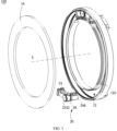
- an embodiment of the present disclosure provides a balance assembly 100 applied in a household appliance 1000.
- the balance assembly 100 includes: a balancing body 10 having a chamber 12 defined therein; a balancer 20 movably located within the chamber 12; a first wireless charging assembly 34; and an energy storage device 30 located outside the balancer 20 and connected to the first wireless charging assembly 34.
- the first wireless charging assembly 34 is configured to receive a charging energy wirelessly transmitted by the household appliance 1000 and charge the energy storage device 30 with the charging energy.
- the energy storage device 30, the first wireless charging assembly 34, and the balancing body 10 are mounted within a cavity 200 of the household appliance 1000.
- the chamber 12 has a first conductive structure 24 provided on an inner wall 122 thereof.
- the first conductive structure 24 is electrically connected to the energy storage device 30.
- the balancer 20 includes a second conductive structure 24 movably connected to the first conductive structure 11.
- the energy storage device 30 is capable of supplying power to the balancer 20 by the first conductive structure 11 and the speed regulating structure 24.
- the first wireless charging assembly 34 is capable of charging the energy storage device 30 with the charging energy wirelessly transmitted by the household appliance 1000.
- the balancer 20 in the balancing body 10 is powered by the energy storage device 30 through the first conductive structure 11 and the second conductive structure 24. In this way, the power supply to the energy storage device 30 by a brush can be avoided, and a sealing performance of the balancing body 10 and a reliability of the power supply can be improved.
- the energy storage device 30 is located outside the balancer 20, a weight of the balancer 20 itself can thus be reduced and the balancer 20 is more easily driven. Further, in a case where a plurality of balancers 20 is provided, the plurality of balancers 20 can share the energy storage device 30 and the balance assembly 100 can be supplied by a uniform power supply at a lower cost.
- the energy storage device 30 is located outside of the balancer 20. It should be understood that the energy storage device 30 is not mounted on the balancer 20. The energy storage device 30 may be fixed to some other physical locations outside the balancer 20, such as onto the cavity 200.
- the main controller 400 is in wireless communication with the controller 21.
- the main controller 400 may include a first wireless communication module and a wireless gateway.
- the controller 21 may include a second wireless communication module.
- the second wireless communication module, the first wireless communication module, and the wireless gateway are configured to form a wireless communication network.
- Each of the first wireless communication module and the second wireless communication module may be a WiFi module, a Bluetooth module, a NRF module, a ZigBee module, or a mobile communication module (e.g., a 4G module, a 5G module, etc.).
- the first wireless communication module and the second wireless communication module have a plurality of options and are highly replaceable.
- a selection of the wireless gateway is adapted to types of the first wireless communication module and the second wireless communication module.
- the balancing body 10 is in an annular shape. It will be understood that in other embodiments, the balancing body 10 may be in other shapes, such as a flat plate shape, which is not specifically limited herein.
- the balancing body 10 includes a bearing ring 15, an end cap 16, an annular connection member 14, and an annular base 17.
- the chamber 12 is formed within the annular base 17.
- the end cap 16 is connected to the annular base 17 and seals the chamber 12.
- the bearing ring 15 is mounted on an inner wall 122 of the chamber 12.
- Two connection members 14 may be provided, and mounted on both sides of the bearing ring 15, respectively. Due to the annular shape of the balancing body 10, it is possible to allow a circumferential movement of the balancer 20 within the chamber 12 of the balancing body 10.
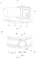
- the balancer 20 includes a bracket 22 on which the second conductive structure 24 is mounted.
- the connection between the first conductive structure 11 and the second conductive structure 24 may also serve to guide the movement of the balancer 20.
- two second conductive structures 24 may be provided, and the two second conductive structures 24 are mounted at both ends of the bracket 22, respectively.
- the second conductive structures 24 may be mounted on the bracket 22 by connection plates 25. In other embodiments, one or more second conductive structures 24 may be provided, which is not specifically limited herein.
- FIG. 5 and FIG. 6 the movement of the balancer 20 is guided by the first conductive structure 11 and the second conductive structure 24 together.
- the second conductive structure 24 is mounted at both ends of the balancer 20, and the first conductive structure 11 is mounted on the inner wall 122 of the chamber 12.
- the first conductive structure 11 and the second conductive structure 24 cooperate with each other to guide the movement of the balancer 20 together.
- the balancer 20 may generate a shake when moving within the chamber 12, and may cause the balancer 20 to deviate from its movement trajectory when moving at the high speed, thereby affecting the movement of the balancer 20.
- the first conductive structure 11 and the second conductive structure 24, on the one hand can conduct electricity, and on the one hand can guide the balancer 20 to move when attaching on the inner wall 122 of the chamber 12. Meanwhile, a stability of the balancer 20 can be increased.
- the bracket 22 may be made of a metal material such as a thick stainless-steel plate, for fixing the second conductive structure 24 and other components of the balancer 20. In this way, it is possible to avoid the components of the balancer 20 from loosening during an operation of the balancer 20, and the bracket 22 would not be deformed throughout the operation of the balancer 20.
- the balancer 20 includes a control board 26.
- the second conductive structure 24 includes a first conductive element 242 and a second conductive element 244, and a first conductive structure 11 includes a first guide rail 112 and a second guide rail 114.
- the first conductive element 242 is connected to the first guide rail 112, and the second conductive element 244 is connected to the second guide rail 114.
- the first conductive element 242 and the second conductive element 244 are electrically connected to the control board 26, respectively.
- the second conductive structure 24 can receive power from the energy storage device 30 by the first conductive structure 11 and transmit the power to the control board 26, and the control power can supply the electrical energy to the load of the balancer 20.
- the second conductive structure 24 includes a conductive shaft 240 (e.g., a copper shaft).
- the conductive shaft 240 is stationary.
- Two conductive shafts 240 may be provided, and the two conductive shafts 240 pass through the first conductive element 242 and the second conductive element 244, respectively.
- the first conductive element 242 and the second conductive element 244 may each rotate around the conductive shaft 240.
- a wire 245 may be electrically connected the conductive shaft 240 and the energy storage device 30, and the electrical energy is transmitted from the conductive shaft 240 and the wire 245 to the energy storage device 30.
- the first conductive element 242 is connected to the first guide rail 112 and the second conductive element 244 is connected to the second guide rail 114, according to a principle that metals have electrical conductivity, the first conductive element 242 can receive power via the first guide rail 112, and the second conductive element 244 can receive power via the second guide rail 114. And then, the first conductive element 242 and the second conductive element 244 transmit the electrical energy to the conductive shaft 240 and the wire 245, respectively, and then to the control board 26 of the balancer 20, which in turn may provide the electrical energy to a load of the balancer 20. In this way, the control board 26 of the balancer 20 can receive power from the battery via the first conductive structure 11 and the second conductive structure 24.
- each of the first guide rail 112 and the second guide rail 114 may be an annular guide rail provided on the inner wall 122 of the chamber 12.
- the first guide rail 112 and the second guide rail 114 are electrically conductive, for example made of copper.
- the first conductive element 242 and the second conductive element 244 may also be made of copper.
- the first guide rail 112 and the second guide rail 114 as well as the first conductive element 242 and the second conductive element 244 may also be made of other conductive materials, which will not be limited herein.
- the balancer 20 may include a control compartment 29 in which the control board 26 is placed.
- the controller 21 of the balancer 20 is disposed on the control board 26.
- each of the first conductive element 242 and the second conductive element 244 includes a conductive wheel 241.
- the conductive wheel 241 of the first conductive element 242 is movably connected to the first guide rail 112, and the conductive wheel 241 of the second conductive element 244 is movably connected to the second guide rail 114.
- the conductive wheel 241 may be a roller and may be circular in shape, and the conductive wheel 241 may be rolled and moved on the guide rails. In this way, during the movement of the balancer 20, less friction force would be generated between the first conductive structure 11 and the second conductive structure 24, which reduces a resistance during the movement of the balancer 20. Thus, it is beneficial to reduce the power of the balancer 20 and provide the energy storage device 30 with a longer power supply time.
- the conductive wheels 241 may roll on the rails.
- the two conductive wheels 241 of the first conductive element 242 may clamp the first guide rail 112.
- the two conductive wheels 241 of the second conductive element 244 may clamp the second guide rail 114.
- the first conductive structure 11 and the second conductive structure 24 may be connected to each other by embedding or engagement, and can also provide guiding and electricity conduction, which will not be limited herein.
- the elastic member 2462 includes a first elastic member 2462a and a second elastic member 2462b.
- the first elastic member 2462a is connected to the base 246 and the first connection frame 248a.
- the second elastic member 2462b is connected to the base 246 and the second connection frame 248b.
- the first connection frame 248a and the second connection frame 248b tightly connect the first conductive element 242 to the first guide rail 112 by the first elastic member 2462a and tightly connect the second conductive element 244 to the second guide rail 114 by the second elastic member 2462b.
- risks of a poor contact between the first conductive element 242 and the first guide rail 112 and a poor contact between the second conductive element 244 and the second guide rail 114 due to assembly errors and manufacturing errors can be avoided.
- the base 246 has a blind hole defined therein.
- the blind hole is configured to receive an elastic member 2462.
- a connection post 247 is located below the connection frame 248.
- the elastic member 2462 is connected to the connection post 247 at one end thereof and is abutted against a bottom wall of the blind hole at the other end thereof.
- the elastic member 2462 may be connected to the connection frame 248 by the connection post 247.
- the connection post 247 may include a first connection post 247a by which the first connection frame 248a is connected to the first elastic member 2462a connected and a second connection post 247b by which the second connection frame 248a is connected to the second elastic member 2462b.
- each of the second conductive structures 24 may include two elastic members 2462 such that the base 246 may be subjected to a greater force. In other embodiments, each of the second conductive structures 24 may include one, or three, or other numbers of elastic members 2462, which is not specifically limited herein.
- the elastic member 2462 may be a spring such as a coil spring, a leaf spring, a torsion bar spring, a gas spring, a rubber spring or the like, which is not specifically limited herein.
- the balancer 20 includes a driving assembly 23.
- the driving assembly 23 includes a driving member 232 and a rotation member 234.
- the driving member 232 is connected to the rotation member 234 and the control board 26.
- the control board 26 is configured to control the driving member 232 to drive the rotation member 234 to rotate so as to drive the balancer 20 to move in the chamber 12.
- the driving member 232 can receive power from the battery by the control board 26.
- the balancer 20 is driven by the driving assembly 23 to move, so that a position of the balancer 20 within the chamber 12 can be changed, thereby reducing the vibration of the household appliance 1000.
- the control board 26 of the balancer 20 is connected to the energy storage device 30 by the first conductive structure 11 and the second conductive structure 24.
- the driving member 232 is connected to the control board 26.
- the control board 26 is capable of controlling a voltage of the driving member 232 to change a state of the driving member 232.
- the driving member 232 may include a motor to drive the rotation member 234 to rotate, which in turn drives the balancer 20 to move within the chamber 12. In this way, a rapid reduction or an offset of the eccentric mass of the cavity 200 can be realized by the balancer 20, thereby reducing the vibration of the household appliance 1000.
- the balancer 20 can be controlled to move or stop the movement in a clockwise or counterclockwise direction by controlling the motor to perform a forward or reverse rotation or stop the rotation.
- the chamber 12 includes the inner wall 122.
- the inner wall 122 has a bearing ring 15.
- the bearing ring 15 has a connection member 14 provided on an inner side thereof.
- a modulus of the tooth portion is 1 or 1.25.
- the gear 2342 of the rotation member 234 is engaged with the tooth portion to rotate.
- the balancer 20 can be driven to move relative to the tooth portion while the gear 2342 is rotating.
- the bearing ring 15 may be omitted, and the connection member 14 may be disposed directly on the inner wall 122 of the chamber 12.
- the driving assembly 23 includes a speed regulating structure 236 be connected to the driving member 232 and the rotation member 234.
- a movement speed of the balancer 20 on the one hand and a movement direction of the balancer 20 on the other hand can be controlled by the speed regulating structure 236.
- the bracket 22 includes a first side surface 222 and a second side surface 224 opposite to each other.
- the first side surface 222 faces towards the rotation axis X of the cavity 200.
- the speed regulating structure 236 is mounted on the second side surface 224 of the bracket 22.
- the speed regulating structure 236 may include a housing 238 and an adjustment assembly disposed within the housing 238.
- the housing 238 may be made of a solid thick steel plate which is not easily deformed, and the whole housing 238 has a cuboid shape. In other embodiments, the housing 238 may also be of other shapes such as a cube, a prism, or a cylinder.
- the inner wall 122 has two connection members 14 provided thereon, and the rotation member 234 includes two gears 2342 located on both sides of the housing 238 and engaged with the two connection members 14, respectively.
- the speed regulating structure 236 can adjust a speed at which the driving member 232 drives the rotation member 234 to rotate, thereby adjusting the movement speed of the balancer 20.
- the speed regulating structure 236 includes a first-stage transmission structure 2362 and a second-stage transmission structure 2364.
- the first-stage transmission structure 2362 is connected to an output shaft 2322 of the driving member 232
- the second-stage transmission structure 2364 is connected the first-stage transmission structure 2362 and the rotation member 234. In this way, a speed reduction ratio of the balancer 20 can be achieved by the two-stage transmission structure.
- the first-stage transmission structure 2362 includes a worm 23622 and a worm wheel 23624.
- the second-stage transmission structure 2364 includes a first gear 23642 and a second gear 23644.
- the worm 23622 is connected to the output shaft 2322 of the driving member 232 and the worm wheel 23624, and the worm wheel 23624 is fixedly connected to the first gear 23642.
- the first gear 23642 is engaged with the second gear 23644.
- Each of the first gear 23642 and the second gear 23644 has a modulus of 0.5 and a gear ratio of 1:3.
- the second gear 23644 is connected to the rotation member 234. In this way, the two-stage transmission can be realized.
- the worm wheel 23624 and worm 23622 also serve as a limiting function.
- the balancer 20 can be stably maintained in the balancing body 10 when the driving member 232 is not operated.
- the speed reduction ratio of the balancer 20 may have a speed reduction ratio more than 75 by the two-stage transmission.
- first gear 23642 is fixedly connected to the worm wheel 23624, and the second gear 23644 is engaged with the first gear 23642.
- the second gear 23644 are connected to a rotation shaft 231 at opposite sides thereof, and the rotation shaft 231 is connected to the rotation member 234 to realize a synchronous rotation.
- the driving member 232 drives the worm 23622 to rotate by the output shaft 2322, and then the worm 23622 drives the worm wheel 23624 engaged with the worm 23622 to rotate, so as to realize a first-stage transmission.
- the worm wheel 23624 further drives the first gear 23642, and then the first gear 23642 drives the second gear 23644, so as to realize a second-stage transmission.
- the second gear 23644 drives the rotation member 234 to rotate synchronously by the rotation shaft 231, thus driving the balancer 20 to move within the chamber 12.
- the rotation shaft 231 may be a cylindrical shaft or a non-cylindrical shaft. In the illustrated embodiment, the rotation shaft 231 is a D-shaped shaft.
- the balancer 20 includes a bearing structure 27.
- the driving assembly 23 is disposed on the bearing structure 27.
- the bearing structure 27 is in contact with the inner wall 122 of the chamber 12 and is configured to move along the inner wall 122 of the chamber 12 during the movement of the balancer 20 to bear a centrifugal force generated when the balancer 20 moves within the chamber 12. In this way, the bearing structure 27 can bear the centrifugal force of the balancer 20 in a circumferential movement of the cavity 200, thereby ensuring that the balancer 20 moves properly.
- the bearing structure 27 is entirely made of a metal material, which is solid and not easily deformed, and can carry the whole driving assembly 23 stably to ensure a normal operation of the driving assembly 23.
- the bearing structure 27 moves along the inner wall 122 of the chamber 12, and bears the centrifugal force of the balancer 20 in the circumferential movement of the cavity 200 through the contact with the inner wall 122 of the chamber 12.
- the bearing structure 27 is able to ensure that the balancer 20 can move normally even when a rotating speed of the cavity 200 is greater than or equal to 800 rpm.
- the bearing plate 272 may be made of a thick stainless-steel plate, and the bearing plate 272 has two rolling members 274 provided at both ends thereof, respectively.
- the rolling member 274 include a bearing 2742 and a spindle 2744 passed through the bearing 2742.
- the spindle 2744 is fixedly connected to the bearing plate 272 by means of metal welding, adhesive bonding, screw connection, or snap connection, which is not limited herein.
- the bearing plate 272 also has a plurality of mounting holes 2722 defined thereon.
- the plurality of mounting holes 2722 is configured to mount the bearing structure 27 to the balancer 20.
- fasteners may pass through the plurality of mounting holes 2722 to be connected to the housing so as to mount the bearing structure 27 to the housing.
- the mounting holes 2722 may have a circular, rectangular, oval shape or the like.
- the bearing structure 27 may be an arc-shaped block with a predetermined curvature, such as a bearing structure 27 made of a smooth material such as POM, etc.
- the arc-shaped block may slide within the chamber 12 as the driving member 232 drives the rotation member 234 to drive the balancer 20 to move.
- the balance assembly 100 includes an identification member 40 and a displacement detection member 50.
- the balance assembly 100 is configured to cause a relative movement between the identification member 40 and the displacement detection member 50 in response to the driving assembly 23 driving the balancer 20 to move within the chamber 12.
- the displacement detection member 50 is configured to detect the number of times of the identification member 40 passing by the displacement detection member 50.
- the number of times of the identification member 40 passing by the displacement detection member 50 is related to the position of the balancer 20. In this way, the displacement detection member 50 can detect the number of times of the identification member 40 passing by the displacement detection member 50, and thus can obtain a movement distance of the balancer 20, so that the position of the balancer 20 can be determined.
- the identification member 40 moves relative to the displacement detection member 50 and passes by the displacement detection member 50, and the number of times of the identification member 40 passing by the displacement detection member 50 is correlated with the position of the balancer 20. Therefore, the movement distance of the balancer 20 can be determined by detecting the number of times of the identification member 40 passing by the displacement detection member 50, and the position of the balancer 20 can be then determined in combination with an initial position 121 of the balancer 20.
- the initial position 121 may refer to a position of the balancer 20 before it begins to move within the chamber 12, or to a certain position that can be determined during the movement of the balancer 20.
- the identification member 40 may be disposed on the rotation member 234 or the inner wall 122 of the chamber 12. In this way, the identification member 40 can be determined in several manners, thereby improving a flexibility of the identification member 40 during its installation.
- the identification member 40 is disposed on the rotation member 234.
- the rotation member 234 includes the gear 2342.
- the chamber 12 includes the inner wall 122.
- the inner wall 122 has the connection member 14 provided thereon.
- the gear 2342 is engaged with the tooth portion of the connection member 14.
- the identification member 40 is a tooth 23422 of the gear 2342 or a tooth of the tooth portion of the connection member 14.
- the tooth 23422 of the gear 2342 may be used as the identification member 40, and thus no additional identification member 40 is required.
- the identification member 40 may also be a tooth of the tooth portion of the connection member 14.
- a groove 23424 is formed between the teeth of the gear 2342 or the teeth portion of the connection member 14, and the tooth 23422 and the groove 23424 are evenly arrange in an alternating manner.
- the gear 2342 is engaged with and rotated relative to the tooth portion of the connection member 14.
- the balancer 20 can be driven to move relative to the connection member 14.
- the tooth 23422 of the gear 2342 or the tooth of the tooth portion of the connection member 14 may be used as the identification member 40, and correspondingly, the displacement detection member 50 can be mounted on the balancer 20.
- the displacement detection member 50 includes a detection surface facing towards the identification member 40.
Landscapes
- Engineering & Computer Science (AREA)
- Textile Engineering (AREA)
- Charge And Discharge Circuits For Batteries Or The Like (AREA)
Claims (13)
- Haushaltsgerät (1000), umfassend einen Körper (300), einen Hohlraum (200), der drehbar mit dem Körper (300) verbunden ist, und eine Auswuchtungsanordnung (100), wobei die Auswuchtungsanordnung (100) Folgendes umfasst: einen Auswuchtungskörper (10), in dem eine Kammer (12) definiert ist, eine Auswuchtvorrichtung (20), die beweglich in der Kammer (12) angeordnet ist, eine erste drahtlose Ladeanordnung (34) und eine Energiespeichervorrichtung (30), die außerhalb der Auswuchtvorrichtung (20) angeordnet und mit der ersten drahtlosen Ladeanordnung (34) verbunden ist, wobei die Energiespeichervorrichtung (30), die erste drahtlose Ladeanordnung (34) und der Auswuchtungskörper (10) in dem Hohlraum (200) montiert sind, wobei die erste drahtlose Ladeanordnung (34) dafür konfiguriert ist, eine Ladeenergie zu empfangen, die drahtlos durch das Haushaltsgerät (1000) übertragen wird, und die Energiespeichervorrichtung (30) mit der Ladeenergie zu laden, wobei die Kammer (12) eine erste leitende Struktur (11), die an einer ihrer Innenwände bereitgestellt ist, und einen Draht (245) umfasst, wobei die erste leitende Struktur (11) eine erste Führungsschiene (112) und eine zweite Führungsschiene (114) umfasst, wobei die erste Führungsschiene (112) und die zweite Führungsschiene (114) über den Draht (245) elektrisch mit der Energiespeichervorrichtung (30) verbunden sind, wobei die Auswuchtvorrichtung (20) eine zweite leitende Struktur (24) umfasst, die beweglich mit der ersten leitenden Struktur (11) verbunden ist, und wobei die Energiespeichervorrichtung (30) in der Lage ist, durch die erste leitende Struktur (11) und die zweite leitende Struktur (24) Leistung an die Auswuchtvorrichtung (20) zu liefern,wobei das Haushaltsgerät (1000) ferner eine zweite drahtlose Ladeanordnung (36) umfasst,wobei zweite drahtlose Ladeanordnung (36) in dem Körper (300) montiert ist undwobei die erste drahtlose Ladeanordnung (34) eine Empfangsspule (342) umfasst und die zweite drahtlose Anordnung (36) eine Übertragungsspule (362) umfasst, wobei die Empfangsspule (342) und die Übertragungsspule (362) voneinander beabstandet und einander gegenüber angeordnet sind, die Übertragungsspule (362) in der Lage ist, die Ladeenergie an die Empfangsspule (342) zu übertragen, und die Empfangsspule (342) in der Lage ist, die Energiespeichervorrichtung (30) mit der empfangenen Ladeenergie zu laden, wobei die Empfangsspule (342) und die Übertragungsspule (362) koaxial entlang einer Drehachse X des Hohlraums (200) angeordnet sind.
- Haushaltsgerät (1000) nach Anspruch 1, wobei die Auswuchtvorrichtung (20) eine Steuertafel (26) umfasst, wobei die zweite leitende Struktur (24) ein erstes leitendes Element (242) und ein zweites leitendes Element (244) umfasst, wobei das erste leitende Element (242) mit der ersten Führungsschiene (112) verbunden ist, das zweite leitende Element (244) mit der zweiten Führungsschiene (114) verbunden ist und sowohl das erste leitende Element (242) als auch das zweite leitende Element (244) jeweils elektrisch mit der Steuertafel (26) verbunden sind.
- Haushaltsgerät (1000) nach Anspruch 2, wobei das erste leitende Element (242) und das zweite leitende Element (244) jeweils ein leitendes Rad (241) umfassen, wobei das leitende Rad (241) des ersten leitenden Elements (242) beweglich mit der ersten Führungsschiene (112) verbunden ist und das leitende Rad (241) des zweiten leitenden Elements (244) beweglich mit der zweiten Führungsschiene (114) verbunden ist.
- Haushaltsgerät (1000) nach Anspruch 3, wobei das erste leitende Element (242) und das zweite leitende Element (244) jeweils zwei leitende Räder (241) und eine Verbindungsstange (243) umfassen, wobei die zwei leitenden Räder (241) durch die Verbindungsstange (243) miteinander verbunden sind, wobei die erste Führungsschiene (112) teilweise in einem Zwischenraum zwischen den zwei leitenden Rädern (241) des ersten leitenden Elements (242) angeordnet ist und wobei die zweite Führungsschiene (114) teilweise in einem Zwischenraum zwischen den zwei leitenden Rädern (241) des zweiten leitenden Elements (244) angeordnet ist.
- Haushaltsgerät (1000) nach Anspruch 3, wobei das leitende Rad (241) des ersten leitenden Elements (242) elastisch an der ersten Führungsschiene (112) anliegt und wobei das leitende Rad (241) des zweiten leitenden Elements (242) elastisch an der zweiten Führungsschiene (114) anliegt.
- Haushaltsgerät (1000) nach Anspruch 5, wobei die zweite leitende Struktur (24) ferner eine Basis (246) und einen Verbindungsrahmen (248), der beweglich mit der Basis (246) verbunden ist, umfasst, wobei das erste leitende Element (242) und das zweite leitende Element (244) an dem Verbindungsrahmen (248) montiert sind.
- Haushaltsgerät (1000) nach Anspruch 6, wobei an der Basis (246) ein elastisches Element (2462) bereitgestellt ist, wobei das elastische Element (2462) mit dem Verbindungsrahmen (248) verbunden und dafür konfiguriert ist, den Verbindungsrahmen (248) mit einer Kraft zum elastischen Anlegen des leitenden Rades (241) des ersten leitenden Elements (242) an die erste Führungsschiene (112) und zum elastischen Anlegen des leitenden Rades (241) des zweiten leitenden Elements (244) an die zweite Führungsschiene (114) zu versorgen.
- Haushaltsgerät (1000) nach Anspruch 2, wobei die Auswuchtvorrichtung (20) ferner eine Antriebsanordnung (23) umfasst, wobei die Antriebsanordnung (23) ein Drehelement (234) und ein Antriebselement (232) umfasst, das mit dem Drehelement (234) und der Steuertafel (26) verbunden ist, und wobei die Steuertafel (26) dafür konfiguriert ist, das Antriebselement (232) zu steuern, um eine Drehung des Drehelements (234) anzutreiben, wobei die Auswuchtvorrichtung (20) durch die Drehung des Drehelements (234) angetrieben wird, um die Auswuchtvorrichtung (20) zur Bewegung in der Kammer (12) anzutreiben.
- Haushaltsgerät (1000) nach Anspruch 8, wobei: in der Kammer (12) ein ringförmiges Verbindungselement (14) bereitgestellt ist, wobei das ringförmige Verbindungselement (14) einen Zahnabschnitt aufweist, der an seiner Innenseite bereitgestellt ist, und wobei das Drehelement (234) ein Zahnrad (2342) umfasst, das mit dem Zahnabschnitt in Eingriff steht, oder die Antriebsanordnung (23) ferner eine Geschwindigkeit regelnde Struktur (236) umfasst und wobei das Antriebselement (232) und das Drehelement (234) durch die Geschwindigkeit regelnde Struktur (236) verbunden sind oder die Auswuchtvorrichtung (20) ferner eine Lagerstruktur (27) umfasst und wobei die Antriebsanordnung (23) an der Lagerstruktur (27) angeordnet ist, wobei die Lagerstruktur (27) in Kontakt mit der Innenwand der Kammer steht und dafür konfiguriert ist, während einer Bewegung der Auswuchtvorrichtung in der Kammer durch Bewegen entlang der Innenwand der Kammer während der Bewegung der Auswuchtvorrichtung (20) eine Fliehkraft zu tragen.
- Haushaltsgerät (1000) nach Anspruch 8, ferner umfassend: ein Identifizierungselement (40) und ein Verlagerungserkennungselement (50), das dafür konfiguriert ist, die Anzahl der Male zu erkennen, mit der das Identifizierungselement (40) am Verlagerungserkennungselement (50) vorbeiläuft, wobei sich die Anzahl der Male, mit der das Identifizierungselement (40) am Verlagerungserkennungselement (50) vorbeiläuft, auf eine Position der Auswuchtvorrichtung (20) bezieht und wobei die Auswuchtungsanordnung (100) dafür konfiguriert ist, in Reaktion darauf, dass die Antriebsanordnung (23) die Auswuchtvorrichtung (20) zur Bewegung in der Kammer (12) antreibt, eine relative Bewegung zwischen dem Identifizierungselement (40) und dem Verlagerungserkennungselement (50) zu bewirken.
- Haushaltsgerät (1000) nach Anspruch 8, ferner umfassend: ein Korrekturelement (14) und ein Korrekturerkennungselement (70), das dafür konfiguriert ist, das Korrekturelement (60) zu erkennen, um einen Positionsfehler der Auswuchtvorrichtung (20) zu beseitigen, wobei die Auswuchtungsanordnung (100) dafür konfiguriert ist, während der Bewegung der Auswuchtvorrichtung (20) eine relative Bewegung zwischen dem Korrekturelement (14) und dem Korrekturerkennungselement (70) zu bewirken.
- Haushaltsgerät (1000) nach einem der Ansprüche 1 bis 11, ferner umfassend eine Hauptsteuerung (400), wobei die Auswuchtvorrichtung (20) ferner eine Steuerung (21) in Verbindung mit der Hauptsteuerung (400) umfasst.
- Haushaltsgerät (1000) nach einem der Ansprüche 1 bis 11, wobei der Hohlraum (200) ein Waschhohlraum (200) ist, wobei der Körper (300) ein Gehäuse und einen Wasser aufnehmenden Hohlraum (201) umfasst, wobei der Waschhohlraum (200) drehbar in dem Wasser aufnehmenden Hohlraum (201) angeordnet ist und der Wasser aufnehmende Hohlraum (201) und der Waschhohlraum (200) in dem Gehäuse angeordnet sind, wobei der Auswuchtungskörper (10) vorzugsweise eine Mittelachse aufweist, die parallel zu einer Drehachse des Waschhohlraums (200) liegt oder mit dieser deckungsgleich ist.
Applications Claiming Priority (3)
| Application Number | Priority Date | Filing Date | Title |
|---|---|---|---|
| CN201922501445.9U CN211395025U (zh) | 2019-12-31 | 2019-12-31 | 平衡组件和家用电器 |
| CN201911422166.1A CN113123082B (zh) | 2019-12-31 | 2019-12-31 | 平衡组件和家用电器 |
| PCT/CN2020/135819 WO2021135895A1 (zh) | 2019-12-31 | 2020-12-11 | 平衡组件和家用电器 |
Publications (3)
| Publication Number | Publication Date |
|---|---|
| EP4067553A1 EP4067553A1 (de) | 2022-10-05 |
| EP4067553A4 EP4067553A4 (de) | 2023-01-25 |
| EP4067553B1 true EP4067553B1 (de) | 2025-07-02 |
Family
ID=76687019
Family Applications (1)
| Application Number | Title | Priority Date | Filing Date |
|---|---|---|---|
| EP20910331.6A Active EP4067553B1 (de) | 2019-12-31 | 2020-12-11 | Haushaltsgerät mit unwuchtausgleichsvorrichtung |
Country Status (3)
| Country | Link |
|---|---|
| US (1) | US11821130B2 (de) |
| EP (1) | EP4067553B1 (de) |
| WO (1) | WO2021135895A1 (de) |
Families Citing this family (2)
| Publication number | Priority date | Publication date | Assignee | Title |
|---|---|---|---|---|
| CN115679630A (zh) * | 2021-07-27 | 2023-02-03 | 无锡小天鹅电器有限公司 | 一种平衡组件、平衡装置及洗涤设备 |
| CN115679633A (zh) * | 2021-07-27 | 2023-02-03 | 无锡小天鹅电器有限公司 | 一种平衡环、平衡组件及衣物处理设备 |
Family Cites Families (14)
| Publication number | Priority date | Publication date | Assignee | Title |
|---|---|---|---|---|
| JPH03251294A (ja) * | 1990-02-28 | 1991-11-08 | Matsushita Electric Ind Co Ltd | ドラム式洗濯機 |
| CN102101251B (zh) | 2009-12-17 | 2013-01-23 | 武汉重型机床集团有限公司 | 位置检测控制装置 |
| WO2011115384A2 (ko) | 2010-03-15 | 2011-09-22 | 엘지전자 주식회사 | 세탁장치 및 그 제어방법 |
| KR101806836B1 (ko) | 2011-05-04 | 2017-12-11 | 삼성전자주식회사 | 세탁기 및 그 제어방법 |
| KR101847931B1 (ko) | 2011-08-10 | 2018-05-28 | 엘지전자 주식회사 | 세탁기 |
| WO2013154313A1 (ko) | 2012-04-09 | 2013-10-17 | 엘지전자 주식회사 | 세탁기 |
| US9708740B2 (en) | 2012-06-07 | 2017-07-18 | Samsung Electronics Co., Ltd. | Balancer, balancer housing, washing machine having the same and control method thereof |
| US9441697B2 (en) | 2012-06-07 | 2016-09-13 | Samsung Electronics Co., Ltd. | Balancing module and washing machine having the same |
| KR102091549B1 (ko) * | 2013-06-13 | 2020-03-20 | 삼성전자주식회사 | 세탁기 및 그 밸런서의 제조 방법 |
| EP3153620B1 (de) * | 2014-06-09 | 2020-02-05 | LG Electronics Inc. | Waschmaschine |
| KR102314533B1 (ko) | 2017-03-20 | 2021-10-18 | 엘지전자 주식회사 | 세탁기 및 그 제어방법 |
| CN211395035U (zh) * | 2019-12-31 | 2020-09-01 | 广东美的白色家电技术创新中心有限公司 | 家用电器 |
| CN211395025U (zh) * | 2019-12-31 | 2020-09-01 | 广东美的白色家电技术创新中心有限公司 | 平衡组件和家用电器 |
| CN211395022U (zh) * | 2019-12-31 | 2020-09-01 | 广东美的白色家电技术创新中心有限公司 | 平衡组件及家用电器 |
-
2020
- 2020-12-11 WO PCT/CN2020/135819 patent/WO2021135895A1/zh not_active Ceased
- 2020-12-11 EP EP20910331.6A patent/EP4067553B1/de active Active
- 2020-12-11 US US17/787,331 patent/US11821130B2/en active Active
Also Published As
| Publication number | Publication date |
|---|---|
| EP4067553A4 (de) | 2023-01-25 |
| EP4067553A1 (de) | 2022-10-05 |
| WO2021135895A1 (zh) | 2021-07-08 |
| US11821130B2 (en) | 2023-11-21 |
| US20230038271A1 (en) | 2023-02-09 |
Similar Documents
| Publication | Publication Date | Title |
|---|---|---|
| CN211395022U (zh) | 平衡组件及家用电器 | |
| CN211395025U (zh) | 平衡组件和家用电器 | |
| CN212388219U (zh) | 平衡组件及家用电器 | |
| US11821130B2 (en) | Balance assembly and household appliance | |
| EP2671995B1 (de) | Ausgleichssystem, Gehäuse für Ausgleichssystem, Waschmaschine damit und Steuerungsverfahren dafür | |
| US9708740B2 (en) | Balancer, balancer housing, washing machine having the same and control method thereof | |
| CN211395024U (zh) | 平衡组件及家用电器 | |
| JP6883442B2 (ja) | 電動工具 | |
| CA2875648A1 (en) | Balancer, balancer housing, washing machine having the same and control method thereof | |
| CN211395023U (zh) | 平衡组件和家用电器 | |
| CN113123083B (zh) | 平衡组件及家用电器 | |
| CN113123081B (zh) | 平衡组件和家用电器 | |
| CN113123082B (zh) | 平衡组件和家用电器 | |
| CN108622229B (zh) | 一种agv用翻转机构、底盘、agv | |
| WO2022021729A1 (zh) | 平衡组件及家用电器 | |
| CN212388221U (zh) | 平衡组件及家用电器 | |
| CN212582228U (zh) | 平衡组件及家用电器 | |
| CN113123076B (zh) | 平衡组件和家用电器 | |
| CN211395010U (zh) | 平衡组件和家用电器 | |
| WO2021135861A1 (zh) | 平衡组件及家用电器 | |
| KR102221293B1 (ko) | 세탁장치 | |
| CN114059293A (zh) | 平衡组件及家用电器 | |
| EP4067554B1 (de) | Balanceanordnung und haushaltsgerät | |
| CN114059296B (zh) | 平衡组件及家用电器 | |
| CN114059295A (zh) | 平衡组件及家用电器 |
Legal Events
| Date | Code | Title | Description |
|---|---|---|---|
| STAA | Information on the status of an ep patent application or granted ep patent |
Free format text: STATUS: THE INTERNATIONAL PUBLICATION HAS BEEN MADE |
|
| PUAI | Public reference made under article 153(3) epc to a published international application that has entered the european phase |
Free format text: ORIGINAL CODE: 0009012 |
|
| STAA | Information on the status of an ep patent application or granted ep patent |
Free format text: STATUS: REQUEST FOR EXAMINATION WAS MADE |
|
| 17P | Request for examination filed |
Effective date: 20220630 |
|
| AK | Designated contracting states |
Kind code of ref document: A1 Designated state(s): AL AT BE BG CH CY CZ DE DK EE ES FI FR GB GR HR HU IE IS IT LI LT LU LV MC MK MT NL NO PL PT RO RS SE SI SK SM TR |
|
| A4 | Supplementary search report drawn up and despatched |
Effective date: 20230104 |
|
| RIC1 | Information provided on ipc code assigned before grant |
Ipc: D06F 34/10 20200101ALN20221222BHEP Ipc: D06F 37/22 20060101AFI20221222BHEP |
|
| DAV | Request for validation of the european patent (deleted) | ||
| DAX | Request for extension of the european patent (deleted) | ||
| GRAP | Despatch of communication of intention to grant a patent |
Free format text: ORIGINAL CODE: EPIDOSNIGR1 |
|
| STAA | Information on the status of an ep patent application or granted ep patent |
Free format text: STATUS: GRANT OF PATENT IS INTENDED |
|
| INTG | Intention to grant announced |
Effective date: 20250424 |
|
| GRAS | Grant fee paid |
Free format text: ORIGINAL CODE: EPIDOSNIGR3 |
|
| GRAA | (expected) grant |
Free format text: ORIGINAL CODE: 0009210 |
|
| STAA | Information on the status of an ep patent application or granted ep patent |
Free format text: STATUS: THE PATENT HAS BEEN GRANTED |
|
| AK | Designated contracting states |
Kind code of ref document: B1 Designated state(s): AL AT BE BG CH CY CZ DE DK EE ES FI FR GB GR HR HU IE IS IT LI LT LU LV MC MK MT NL NO PL PT RO RS SE SI SK SM TR |
|
| REG | Reference to a national code |
Ref country code: GB Ref legal event code: FG4D |
|
| REG | Reference to a national code |
Ref country code: CH Ref legal event code: EP |
|
| REG | Reference to a national code |
Ref country code: DE Ref legal event code: R096 Ref document number: 602020054015 Country of ref document: DE |
|
| REG | Reference to a national code |
Ref country code: IE Ref legal event code: FG4D |
|
| REG | Reference to a national code |
Ref country code: NL Ref legal event code: MP Effective date: 20250702 |
|
| PG25 | Lapsed in a contracting state [announced via postgrant information from national office to epo] |
Ref country code: PT Free format text: LAPSE BECAUSE OF FAILURE TO SUBMIT A TRANSLATION OF THE DESCRIPTION OR TO PAY THE FEE WITHIN THE PRESCRIBED TIME-LIMIT Effective date: 20251103 |
|
| PG25 | Lapsed in a contracting state [announced via postgrant information from national office to epo] |
Ref country code: NL Free format text: LAPSE BECAUSE OF FAILURE TO SUBMIT A TRANSLATION OF THE DESCRIPTION OR TO PAY THE FEE WITHIN THE PRESCRIBED TIME-LIMIT Effective date: 20250702 |
|
| REG | Reference to a national code |
Ref country code: AT Ref legal event code: MK05 Ref document number: 1809359 Country of ref document: AT Kind code of ref document: T Effective date: 20250702 |
|
| PG25 | Lapsed in a contracting state [announced via postgrant information from national office to epo] |
Ref country code: IS Free format text: LAPSE BECAUSE OF FAILURE TO SUBMIT A TRANSLATION OF THE DESCRIPTION OR TO PAY THE FEE WITHIN THE PRESCRIBED TIME-LIMIT Effective date: 20251102 |
|
| PGFP | Annual fee paid to national office [announced via postgrant information from national office to epo] |
Ref country code: DE Payment date: 20251212 Year of fee payment: 6 |
|
| PG25 | Lapsed in a contracting state [announced via postgrant information from national office to epo] |
Ref country code: NO Free format text: LAPSE BECAUSE OF FAILURE TO SUBMIT A TRANSLATION OF THE DESCRIPTION OR TO PAY THE FEE WITHIN THE PRESCRIBED TIME-LIMIT Effective date: 20251002 |
|
| REG | Reference to a national code |
Ref country code: LT Ref legal event code: MG9D |
|
| PG25 | Lapsed in a contracting state [announced via postgrant information from national office to epo] |
Ref country code: AT Free format text: LAPSE BECAUSE OF FAILURE TO SUBMIT A TRANSLATION OF THE DESCRIPTION OR TO PAY THE FEE WITHIN THE PRESCRIBED TIME-LIMIT Effective date: 20250702 |
|
| PG25 | Lapsed in a contracting state [announced via postgrant information from national office to epo] |
Ref country code: FI Free format text: LAPSE BECAUSE OF FAILURE TO SUBMIT A TRANSLATION OF THE DESCRIPTION OR TO PAY THE FEE WITHIN THE PRESCRIBED TIME-LIMIT Effective date: 20250702 |
|
| PG25 | Lapsed in a contracting state [announced via postgrant information from national office to epo] |
Ref country code: HR Free format text: LAPSE BECAUSE OF FAILURE TO SUBMIT A TRANSLATION OF THE DESCRIPTION OR TO PAY THE FEE WITHIN THE PRESCRIBED TIME-LIMIT Effective date: 20250702 |
|
| PGFP | Annual fee paid to national office [announced via postgrant information from national office to epo] |
Ref country code: FR Payment date: 20251212 Year of fee payment: 6 |
|
| PG25 | Lapsed in a contracting state [announced via postgrant information from national office to epo] |
Ref country code: GR Free format text: LAPSE BECAUSE OF FAILURE TO SUBMIT A TRANSLATION OF THE DESCRIPTION OR TO PAY THE FEE WITHIN THE PRESCRIBED TIME-LIMIT Effective date: 20251003 |
|
| PG25 | Lapsed in a contracting state [announced via postgrant information from national office to epo] |
Ref country code: SE Free format text: LAPSE BECAUSE OF FAILURE TO SUBMIT A TRANSLATION OF THE DESCRIPTION OR TO PAY THE FEE WITHIN THE PRESCRIBED TIME-LIMIT Effective date: 20250702 Ref country code: CZ Free format text: LAPSE BECAUSE OF FAILURE TO SUBMIT A TRANSLATION OF THE DESCRIPTION OR TO PAY THE FEE WITHIN THE PRESCRIBED TIME-LIMIT Effective date: 20250702 |
|
| PG25 | Lapsed in a contracting state [announced via postgrant information from national office to epo] |
Ref country code: LV Free format text: LAPSE BECAUSE OF FAILURE TO SUBMIT A TRANSLATION OF THE DESCRIPTION OR TO PAY THE FEE WITHIN THE PRESCRIBED TIME-LIMIT Effective date: 20250702 |
|
| PG25 | Lapsed in a contracting state [announced via postgrant information from national office to epo] |
Ref country code: PL Free format text: LAPSE BECAUSE OF FAILURE TO SUBMIT A TRANSLATION OF THE DESCRIPTION OR TO PAY THE FEE WITHIN THE PRESCRIBED TIME-LIMIT Effective date: 20250702 Ref country code: BG Free format text: LAPSE BECAUSE OF FAILURE TO SUBMIT A TRANSLATION OF THE DESCRIPTION OR TO PAY THE FEE WITHIN THE PRESCRIBED TIME-LIMIT Effective date: 20250702 |
|
| PG25 | Lapsed in a contracting state [announced via postgrant information from national office to epo] |
Ref country code: RS Free format text: LAPSE BECAUSE OF FAILURE TO SUBMIT A TRANSLATION OF THE DESCRIPTION OR TO PAY THE FEE WITHIN THE PRESCRIBED TIME-LIMIT Effective date: 20251002 |
|
| PG25 | Lapsed in a contracting state [announced via postgrant information from national office to epo] |
Ref country code: ES Free format text: LAPSE BECAUSE OF FAILURE TO SUBMIT A TRANSLATION OF THE DESCRIPTION OR TO PAY THE FEE WITHIN THE PRESCRIBED TIME-LIMIT Effective date: 20250702 |
|
| PG25 | Lapsed in a contracting state [announced via postgrant information from national office to epo] |
Ref country code: RO Free format text: LAPSE BECAUSE OF FAILURE TO SUBMIT A TRANSLATION OF THE DESCRIPTION OR TO PAY THE FEE WITHIN THE PRESCRIBED TIME-LIMIT Effective date: 20250702 |
|
| PG25 | Lapsed in a contracting state [announced via postgrant information from national office to epo] |
Ref country code: SM Free format text: LAPSE BECAUSE OF FAILURE TO SUBMIT A TRANSLATION OF THE DESCRIPTION OR TO PAY THE FEE WITHIN THE PRESCRIBED TIME-LIMIT Effective date: 20250702 |
|
| PG25 | Lapsed in a contracting state [announced via postgrant information from national office to epo] |
Ref country code: DK Free format text: LAPSE BECAUSE OF FAILURE TO SUBMIT A TRANSLATION OF THE DESCRIPTION OR TO PAY THE FEE WITHIN THE PRESCRIBED TIME-LIMIT Effective date: 20250702 |
|
| PG25 | Lapsed in a contracting state [announced via postgrant information from national office to epo] |
Ref country code: IT Free format text: LAPSE BECAUSE OF FAILURE TO SUBMIT A TRANSLATION OF THE DESCRIPTION OR TO PAY THE FEE WITHIN THE PRESCRIBED TIME-LIMIT Effective date: 20250702 |
|
| PG25 | Lapsed in a contracting state [announced via postgrant information from national office to epo] |
Ref country code: SK Free format text: LAPSE BECAUSE OF FAILURE TO SUBMIT A TRANSLATION OF THE DESCRIPTION OR TO PAY THE FEE WITHIN THE PRESCRIBED TIME-LIMIT Effective date: 20250702 Ref country code: EE Free format text: LAPSE BECAUSE OF FAILURE TO SUBMIT A TRANSLATION OF THE DESCRIPTION OR TO PAY THE FEE WITHIN THE PRESCRIBED TIME-LIMIT Effective date: 20250702 |
|
| PLBE | No opposition filed within time limit |
Free format text: ORIGINAL CODE: 0009261 |
|
| STAA | Information on the status of an ep patent application or granted ep patent |
Free format text: STATUS: NO OPPOSITION FILED WITHIN TIME LIMIT |