EP4067239B1 - Systèmes de guidage pour installer des structures d'aéronef comme des inverseurs de poussée - Google Patents
Systèmes de guidage pour installer des structures d'aéronef comme des inverseurs de poussée Download PDFInfo
- Publication number
- EP4067239B1 EP4067239B1 EP22157732.3A EP22157732A EP4067239B1 EP 4067239 B1 EP4067239 B1 EP 4067239B1 EP 22157732 A EP22157732 A EP 22157732A EP 4067239 B1 EP4067239 B1 EP 4067239B1
- Authority
- EP
- European Patent Office
- Prior art keywords
- leg
- guide system
- arm
- thrust reverser
- pylon
- Prior art date
- Legal status (The legal status is an assumption and is not a legal conclusion. Google has not performed a legal analysis and makes no representation as to the accuracy of the status listed.)
- Active
Links
Images


Classifications
-
- B—PERFORMING OPERATIONS; TRANSPORTING
- B64—AIRCRAFT; AVIATION; COSMONAUTICS
- B64D—EQUIPMENT FOR FITTING IN OR TO AIRCRAFT; FLIGHT SUITS; PARACHUTES; ARRANGEMENT OR MOUNTING OF POWER PLANTS OR PROPULSION TRANSMISSIONS IN AIRCRAFT
- B64D27/00—Arrangement or mounting of power plants in aircraft; Aircraft characterised by the type or position of power plants
- B64D27/40—Arrangements for mounting power plants in aircraft
-
- B—PERFORMING OPERATIONS; TRANSPORTING
- B64—AIRCRAFT; AVIATION; COSMONAUTICS
- B64D—EQUIPMENT FOR FITTING IN OR TO AIRCRAFT; FLIGHT SUITS; PARACHUTES; ARRANGEMENT OR MOUNTING OF POWER PLANTS OR PROPULSION TRANSMISSIONS IN AIRCRAFT
- B64D29/00—Power-plant nacelles, fairings or cowlings
- B64D29/06—Attaching of nacelles, fairings or cowlings
-
- B—PERFORMING OPERATIONS; TRANSPORTING
- B64—AIRCRAFT; AVIATION; COSMONAUTICS
- B64D—EQUIPMENT FOR FITTING IN OR TO AIRCRAFT; FLIGHT SUITS; PARACHUTES; ARRANGEMENT OR MOUNTING OF POWER PLANTS OR PROPULSION TRANSMISSIONS IN AIRCRAFT
- B64D45/00—Aircraft indicators or protectors not otherwise provided for
- B64D45/04—Landing aids; Safety measures to prevent collision with earth's surface
-
- B—PERFORMING OPERATIONS; TRANSPORTING
- B60—VEHICLES IN GENERAL
- B60T—VEHICLE BRAKE CONTROL SYSTEMS OR PARTS THEREOF; BRAKE CONTROL SYSTEMS OR PARTS THEREOF, IN GENERAL; ARRANGEMENT OF BRAKING ELEMENTS ON VEHICLES IN GENERAL; PORTABLE DEVICES FOR PREVENTING UNWANTED MOVEMENT OF VEHICLES; VEHICLE MODIFICATIONS TO FACILITATE COOLING OF BRAKES
- B60T8/00—Arrangements for adjusting wheel-braking force to meet varying vehicular or ground-surface conditions, e.g. limiting or varying distribution of braking force
- B60T8/17—Using electrical or electronic regulation means to control braking
- B60T8/1701—Braking or traction control means specially adapted for particular types of vehicles
- B60T8/1703—Braking or traction control means specially adapted for particular types of vehicles for aircrafts
-
- B—PERFORMING OPERATIONS; TRANSPORTING
- B64—AIRCRAFT; AVIATION; COSMONAUTICS
- B64C—AEROPLANES; HELICOPTERS
- B64C25/00—Alighting gear
- B64C25/32—Alighting gear characterised by elements which contact the ground or similar surface
- B64C25/42—Arrangement or adaptation of brakes
- B64C25/426—Braking devices providing an automatic sequence of braking
-
- B—PERFORMING OPERATIONS; TRANSPORTING
- B64—AIRCRAFT; AVIATION; COSMONAUTICS
- B64D—EQUIPMENT FOR FITTING IN OR TO AIRCRAFT; FLIGHT SUITS; PARACHUTES; ARRANGEMENT OR MOUNTING OF POWER PLANTS OR PROPULSION TRANSMISSIONS IN AIRCRAFT
- B64D27/00—Arrangement or mounting of power plants in aircraft; Aircraft characterised by the type or position of power plants
- B64D27/02—Aircraft characterised by the type or position of power plants
-
- B—PERFORMING OPERATIONS; TRANSPORTING
- B64—AIRCRAFT; AVIATION; COSMONAUTICS
- B64D—EQUIPMENT FOR FITTING IN OR TO AIRCRAFT; FLIGHT SUITS; PARACHUTES; ARRANGEMENT OR MOUNTING OF POWER PLANTS OR PROPULSION TRANSMISSIONS IN AIRCRAFT
- B64D47/00—Equipment not otherwise provided for
-
- B—PERFORMING OPERATIONS; TRANSPORTING
- B64—AIRCRAFT; AVIATION; COSMONAUTICS
- B64F—GROUND OR AIRCRAFT-CARRIER-DECK INSTALLATIONS SPECIALLY ADAPTED FOR USE IN CONNECTION WITH AIRCRAFT; DESIGNING, MANUFACTURING, ASSEMBLING, CLEANING, MAINTAINING OR REPAIRING AIRCRAFT, NOT OTHERWISE PROVIDED FOR; HANDLING, TRANSPORTING, TESTING OR INSPECTING AIRCRAFT COMPONENTS, NOT OTHERWISE PROVIDED FOR
- B64F5/00—Designing, manufacturing, assembling, cleaning, maintaining or repairing aircraft, not otherwise provided for; Handling, transporting, testing or inspecting aircraft components, not otherwise provided for
- B64F5/10—Manufacturing or assembling aircraft, e.g. jigs therefor
-
- F—MECHANICAL ENGINEERING; LIGHTING; HEATING; WEAPONS; BLASTING
- F02—COMBUSTION ENGINES; HOT-GAS OR COMBUSTION-PRODUCT ENGINE PLANTS
- F02C—GAS-TURBINE PLANTS; AIR INTAKES FOR JET-PROPULSION PLANTS; CONTROLLING FUEL SUPPLY IN AIR-BREATHING JET-PROPULSION PLANTS
- F02C7/00—Features, components parts, details or accessories, not provided for in, or of interest apart form groups F02C1/00 - F02C6/00; Air intakes for jet-propulsion plants
- F02C7/20—Mounting or supporting of plant; Accommodating heat expansion or creep
-
- F—MECHANICAL ENGINEERING; LIGHTING; HEATING; WEAPONS; BLASTING
- F02—COMBUSTION ENGINES; HOT-GAS OR COMBUSTION-PRODUCT ENGINE PLANTS
- F02K—JET-PROPULSION PLANTS
- F02K1/00—Plants characterised by the form or arrangement of the jet pipe or nozzle; Jet pipes or nozzles peculiar thereto
- F02K1/54—Nozzles having means for reversing jet thrust
- F02K1/64—Reversing fan flow
-
- B—PERFORMING OPERATIONS; TRANSPORTING
- B60—VEHICLES IN GENERAL
- B60T—VEHICLE BRAKE CONTROL SYSTEMS OR PARTS THEREOF; BRAKE CONTROL SYSTEMS OR PARTS THEREOF, IN GENERAL; ARRANGEMENT OF BRAKING ELEMENTS ON VEHICLES IN GENERAL; PORTABLE DEVICES FOR PREVENTING UNWANTED MOVEMENT OF VEHICLES; VEHICLE MODIFICATIONS TO FACILITATE COOLING OF BRAKES
- B60T2210/00—Detection or estimation of road or environment conditions; Detection or estimation of road shapes
- B60T2210/10—Detection or estimation of road conditions
- B60T2210/12—Friction
-
- B—PERFORMING OPERATIONS; TRANSPORTING
- B64—AIRCRAFT; AVIATION; COSMONAUTICS
- B64F—GROUND OR AIRCRAFT-CARRIER-DECK INSTALLATIONS SPECIALLY ADAPTED FOR USE IN CONNECTION WITH AIRCRAFT; DESIGNING, MANUFACTURING, ASSEMBLING, CLEANING, MAINTAINING OR REPAIRING AIRCRAFT, NOT OTHERWISE PROVIDED FOR; HANDLING, TRANSPORTING, TESTING OR INSPECTING AIRCRAFT COMPONENTS, NOT OTHERWISE PROVIDED FOR
- B64F5/00—Designing, manufacturing, assembling, cleaning, maintaining or repairing aircraft, not otherwise provided for; Handling, transporting, testing or inspecting aircraft components, not otherwise provided for
- B64F5/50—Handling or transporting aircraft components
Definitions
- the present disclosure relates generally to aircraft and, more particularly, to guides for installing an aircraft thrust reverser section to a pylon.
- Aircraft engines often employ reverse thruster systems to produce a reverse thrust to help decelerate the aircraft upon landing (e.g., after touchdown), thereby reducing brake wear and enabling shorter landing distances.
- document US 2020/325797 A1 in accordance with its abstract, states positioning system and method for positioning engine components on an aircraft, the system including a moveable support for the engine component, a laser assembly, and a system controller.
- First and second lasers of the laser assembly align their respective beams with an engine target position on the aircraft and provide an indication of a first angle of the first laser beam to a reference line, and an indication of a second angle of the second laser beam to the reference line; and the system controller is configured to rotate the moveable support to rotationally position the engine component, determine the vertical distance between the engine component and the target position based at least in part on the first and second angles, and to control a lift mechanism to reduce the vertical distance between the engine component and the engine.
- Document WO 2015/015262 A1 in accordance with its abstract, states a method for installing a pre-assembled powerplant and pylon assembly on an aircraft, the method comprising determining a first length of a first link, determining a second length of a second link, determining a first distance occupyable by the first link between the pylon and the aircraft, determining a second distance occupyable by the second link between the pylon and the aircraft, determining a first result by subtracting the first distance from the first length, determining a second result by subtracting the second distance from the second length, and determining a third result by adding the first result and the second result. If the third result is less than or equal to zero, the first link is installed between the pylon and the aircraft before the second link. If the third result is greater than zero, the second link is installed between the pylon and the aircraft before the first link.
- Document EP 2399827 A2 in accordance with its abstract, states a guide system for translating components of an aircraft engine nacelle, the system including a track assembly and a slider assembly.
- the track assembly includes a track guide member having a track channel.
- the slider assembly translatably engages the track assembly.
- the slider assembly includes a slider body configured to be received within the track channel.
- the slider assembly further includes a slider arm member pivotably coupled to the slider body with a hinge joint disposed within the track channel. The slider arm member extends from the body portion and outwardly of the track assembly.
- An example apparatus includes a first guide system structured to removably couple to a first aircraft structure which is a pylon having a first hinge component.
- a second guide system is structured to removably couple to a second aircraft structure which is a thrust reverser section having a second hinge component.
- the first guide system is to engage the second guide system to enable alignment between the first hinge component and the second hinge component during assembly of the first aircraft structure and the second aircraft structure.
- An example method for installing a thrust reverser section to a pylon includes: removably coupling a first guide to a first structure; removably coupling a second guide to a second structure; coupling the first guide and the second guide; moving the second structure toward the first structure; attaching a hinge pin to couple the first structure and the second structure; and removing the first guide from the first structure and the second guide from the second structure.
- any part e.g., a layer, film, area, or plate
- positioned on e.g., positioned on, located on, disposed on, or formed on, etc.
- the referenced part is either in contact with the other part, or that the referenced part is above the other part with one or more intermediate part(s) located therebetween.
- Stating that any part is in contact with another part means that there is no intermediate part between the two parts.
- Some turbofan engines employ reverse thrust mechanisms to decelerate an aircraft upon landing.
- the reverse thrust produced reduces the forward thrust produced by the turbofan engine and, thus, reduces the speed of the aircraft.
- reverse thrust is produced by redirecting airflow within the engine that would otherwise produce forward thrust.
- Thrust reversers typically include a clam-shell profile.
- the thrust reversers include a first thrust reverser portion or section (e.g., a right-side wall) and a second thrust reverser portion or section (e.g., a left-side wall) that surround an engine core when an aircraft engine is assembled.
- the thrust reverser portions attach to a pylon structure of an aircraft via a hinge pin connection.
- Thrust reverser installation can be ergonomically challenging and require safety protocols.
- the thrust reverser sections are positioned relative to the pylon via a lift system (e.g., a crane, a ground lift, etc.).
- the thrust reverser sections are maneuvered and/or guided relative to the pylon to align hinge apertures of the pylon and thrust reverser sections via a crane (e.g., an overhead crane).
- a crane e.g., an overhead crane
- This assembly technique is not ergonomic. For example, a technician typically lays across a top of the aircraft engine and extend their hand in an area that has limited access to install the pins.
- the thrust reverser load is supported by the crane, which can shift or sway during assembly and increase manufacturing complexity.
- Example guide systems disclosed herein facilitate installation of thrust reversers.
- the guide systems disclosed herein are ergonomic.
- the guide systems disclosed herein enable a first structure or thrust reverser to be securely attached to a second structure or pylon without the need for a technician to climb on and/or lay across the aircraft engine.
- the guide systems disclosed herein remove dependency of a crane to support a load of the thrust reverser when installing hinge pins. The load of the thrust reverser is supported by the pylon via the guide system, thereby eliminating potential for shifting or swaying during installation of the hinge pins.
- the guide systems disclosed herein employ a brace system on an interfacing pylon hinge that can safely support the weight of the thrust reverser and orient the thrust reverser in a manner that enables installation of the thrust reverser/pylon hinge pins after the crane is removed.
- the guide systems disclosed herein greatly improve manufacturability.
- the example guides disclosed herein reduce manufacturing complexity and/or improve manufacturing efficiency.
- Example guide systems disclosed herein can be employed to couple or attached a first aircraft structure and a second aircraft structure.
- a first aircraft structure can include a pylon, an aircraft frame structure, a wingbox and/or any other aircraft structure.
- a second aircraft structure can include a thrust reverser portion, a fan cowl, and/or any other portions of a nacelle and/or any other aircraft structure.
- examples described below are directed to a first aircraft structure as a pylon and a second aircraft structure as a thrust reverser portion, the example guide systems disclosed herein can be employed to attach a fan cowl to a pylon.
- example guide systems disclosed herein can be employed to any other first aircraft structure and a second aircraft structure of an aircraft forming a hinged connection.
- the guide systems disclosed herein can be employed with other vehicles, marine vehicles, frame structures, machines, equipment, buildings, etc.,
- the guide systems disclosed herein can be employed to facilitate and/or enable coupling of two or more structures that couple together via a hinged connection.
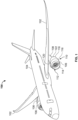
- FIG. 1 illustrates an example aircraft 100 including wings 102 (e.g., a right wing and a left wing) extending laterally outward from a fuselage 104.
- wings 102 e.g., a right wing and a left wing
- Each of the wings 102 of the illustrated example supports an aircraft engine 106 via a pylon 108.
- Each aircraft engine 106 of the illustrated example is a turbofan engine that may embody aspects of the teachings of this disclosure.
- the aircraft engine 106 of FIG. 1 includes a nacelle 110 that houses an engine core 112 and provides an aerodynamic outer surface to reduce drag.
- the nacelle 110 includes an inlet cowl 114 (e.g., an outer panel), a fan cowl 116 (e.g., a clam-shell cowl), and a thrust reverser 118.
- the fan cowl 116 and the thrust reverser 118 encompass or surround the engine core 112.
- the thrust reverser 118 of the illustrated example forms or defines a portion of an outer surface of the nacelle 110.
- the thrust reverser 118 of the illustrated example includes a first thrust reverser portion 120 (e.g., a right-hand thrust reverser wall or first half) and a second thrust reverser portion 122 (e.g., a left-hand thrust reverser wall or second half).
- the thrust reverser 118 is coupled to the pylon 108 in accordance with the teachings disclosed herein. Additionally, the thrust reverser 118 is movably coupled (e.g. pivotally coupled) to the pylon 108 to allow access to the engine core 112 during maintenance.
- the aircraft 100 of FIG. 1 is a commercial aircraft (e.g., a commercial airliner), the examples disclosed herein can be employed with military aircraft, marine vehicles, all-terrain vehicles, etc.
- FIG. 2 is a partial, perspective view of the aircraft 100 of FIG. 1 .
- the aircraft engine 106 of FIG. 2 is shown with exterior components removed such as, for example, the second thrust reverser portion 122 ( FIG. 1 ), the fan cowl 116 ( FIG. 1 ), and other portions of the nacelle 110 ( FIG. 1 ), to show substructure of the aircraft engine 106.
- the aircraft engine 106 e.g., the engine core 112, the nacelle 110, the thrust reverser 118, the fan cowl 116, etc.
- the first thrust reverser portion 120 is shown coupled to the pylon 108 in FIG. 2 .
- the second thrust reverser portion 122 is removed for clarity.
- the second thrust reverser portion 122 is similar to (e.g., is a mirror image of) the first thrust reverser portion 120.
- the hinge 200 of the illustrated example includes a plurality of hinge joints 202 (e.g., lug-and-clevis joints).
- the pylon 108 includes a plurality of first hinge components 204 and the thrust reverser portion 120 includes a plurality of second hinge components 206.
- the first hinge components 204 receive or couple to respective ones of the second hinge components 206 to form the hinge joints 202.
- Each of the first hinge components 204 includes a hinge opening 208 and each of the second hinge components 206 includes a hinge opening 210.
- Each of the hinge j oints 202 receives a hinge pin 212. Only a first hinge joint 202a of FIG. 2 is shown with the hinge pin 212. The hinge pins of the other hinge joints 202 are omitted for clarity.
- the hinge joint 202 is a lug-and-clevis joint.
- the first hinge components 204 of the pylon 108 of the illustrated example are lugs and the second hinge components 206 of the thrust reverser portion 120 of the illustrated example are clevises.
- the thrust reverser portion 120 can include the lugs and the pylon 108 can include the clevises.
- other structures can be employed to define the hinge joints 202 and/or the hinge 200.
- FIG. 3 is a perspective view of an example guide system 300 constructed in accordance with the teachings of this disclosure.
- the guide system 300 of FIG. 3 is shown in a first position 302 (e.g., an installation position or angle).
- the guide system 300 facilitates alignment between the thrust reverser 118 and the pylon 108.
- the guide system 300 facilitates alignment between the hinge openings 208 of the first hinge components 204 and the hinge openings 210 of the second hinge components 206 when the thrust reverser portion 120 couples to the pylon 108.
- the guide system 300 of the illustrated example includes a first guide system 304 (e.g., a first installation tool) and a second guide system 306 (e.g., a second installation tool).
- the first guide system 304 is removably coupled to the pylon 108 (e.g., a first aircraft structure), which includes or supports the first hinge components 204.
- the first guide system 304 includes a body 308, a first leg 310 and a second leg 312.
- the body 308 is a beam having a first end 308a and a second end 308b.
- the body 308 has a length that spans across a first one 314 of the first hinge components 204 and a second one 316 of the first hinge components 204 of the pylon 108.
- first end 308a of the body 308 is removably coupled to the first one 314 of the first hinge components 204 and the second end 308b of the body 308 is coupled to the second one 316 of the first hinge components 204.
- the body 308 can be removably coupled to the pylon 108 via bolts, clamps, and/or another fastener(s).
- the first leg 310 of the illustrated example is spaced from the second leg 312 by a distance that is approximately equal to the length of the body 308.
- the first leg 310 has a first leg end 310a and a second leg end 310b.
- the first leg end 310a is attached to the body 308 and the second leg end 310b projects in a direction away from the body 308.
- the first leg 310 projects from the body 308 at a first leg angle 310c.
- the second leg 312 has a third leg end 312a and a fourth leg end 312b.
- the third leg end 312a is attached to the body 308 and the fourth leg end 312b projects in a direction away from the body 308.
- the second leg 312 projects from the body 308 at a second leg angle 312c.
- the first leg angle 310c of the illustrated example is different from the second leg angle 312c.
- the first leg angle 310c is substantially equal or identical to the second leg angle 312c.
- the first leg 310 includes a first leg connector 318 at the second leg end 310b and the second leg 312 includes a second leg connector 320 at the fourth leg end 312b.
- the first guide system 304 also includes a first brace 322 to support the first leg 310 and a second brace 324 to support the second leg 312.
- the first brace 322 is coupled to the first leg 310 and projects in a direction away from the first leg 310.
- the first brace 322 has a first brace end 322a and a second brace end 322b opposite the first brace end 322a.
- the first brace end 322a is attached to the second leg end 310b of the first leg 310 and the second brace end 322b is removably coupled to the pylon 108 (e.g., the first one 314 of the first hinge components 204).
- the first brace end 322a projects from the second leg end 310b towards the pylon 108.
- the second brace 324 is coupled to the second leg 312 and projects in a direction away from the second leg 312.
- the second brace 324 has a third brace end 324a attached to the fourth leg end 312b and a fourth brace end 324b that removably couples to the pylon 108 (e.g., the second one 316 of the second hinge components 206).
- the first leg 310 and the second leg 312 are fixed to the body 308. Additionally, the first brace 322 and the second brace 324 are fixed to the first leg 310 and the second leg 312, respectively.
- the first leg end 310a is rigidly coupled (e.g., fixed) to the body 308 and the second leg end 310b is rigidly coupled (e.g., fixed) to the first brace end 322a.
- the third leg end 312a is rigidly coupled (e.g., fixed) to the body 308 and the fourth leg end 312b is rigidly coupled (e.g., fixed) to the third brace end 324a.
- first leg 310 is welded to the body 308 and the first brace 322, and the second leg 312 is welded to the body 308 and the second brace 324.
- first leg 310 and/or the second leg 312 attaches to the body 308 and the respective ones of the first brace 322 and the second brace 324 via removable fasteners (e.g., bolts, clamps, fasteners, etc.) to enable disassembly of the first guide system 304 after installation of the thrust reverser portion 120 and the pylon 108.
- the first brace 322 and the second brace 324 are removably coupled to (e.g., supported by) the pylon 108. In other words, the first leg 310, the second leg 312, the first brace 322, and the second brace 324 cannot move relative to the pylon 108 and/or the body 308.
- the second guide system 306 is removably coupled to the thrust reverser portion 120 (e.g., a second aircraft structure), which includes or supports the second hinge components 206.
- the second guide system 306 includes a first guide 330 and a second guide 332.
- the first guide 330 includes a first base 334 and a first arm 336.
- the first base 334 includes a flange 334a that form a recess (e.g., a U-shaped opening).
- the first arm 336 projects from or extends in a direction away from the first base 334.
- the first arm 336 is cantilevered from the first base 334.
- the first arm 336 and the first base 334 form a first arm angle 336c.
- the first arm 336 includes a first arm end 336a that couples (e.g., is fixed) to the first base 334 and a second arm end 336b spaced from the from the first arm end 336a.
- the second arm end 336b is configured to engage the second leg end 310b of the first leg 310.
- the second arm end 336b includes a first arm connector 340 that interfaces (e.g., engages or couples) with the first leg connector 318.
- the first arm connector 340 and the first leg connector 318 of the illustrated example provides a connection that enables the first arm 336 to pivot about the first leg 310.
- the first arm 336 can pivot about to the first leg 310, the first arm 336 is a rigid beam that is fixed to the first base 334.
- the first arm connector 340 has a hook shape and the first leg connector 318 is a protrusion or structure configured to receive the hook.
- the first leg connector 318 and the first arm connector 340 can form a ball-and-socket connection and/or any other connection that enables the first arm 336 to pivot about the first leg connector 318 at an interface provided by the second leg connector 320 and the second arm connector 346.
- the second guide 332 includes a second base 342 and a second arm 344.
- the second base 342 includes a second flange 342a that forms a recess (e.g., a U-shaped opening).
- the second arm 344 projects from or extends in a direction away from the second base 342.
- the second arm 344 is cantilevered from the second base 342.
- the second arm 344 and the second base 342 form a second arm angle 344c.
- the second arm 344 includes a third arm end 344a that couples (e.g., is fixed) to the second base 342 and a fourth arm end 344b spaced from the third arm end 344a.
- the fourth arm end 344b includes a second arm connector 346 that interfaces (e.g., engages or couples) with the second leg connector 320.
- the second arm connector 346 and the second leg connector 320 of the illustrated example provides a connection that enables the second arm 344 to pivot about to the second leg 312.
- the second arm 344 can pivot about to the second leg 312, the second arm 344 is a rigid beam that is fixed to the second base 342.
- the second arm connector 346 has a hook shape and the second leg connector 320 is a protrusion or structure configured to receive the hook.
- the second leg connector 320 and the second arm connector 346 can form a ball-and-socket connection and/or any other connection that enables the second arm 344 to pivot about to the second leg 312 at an interface provided by the second leg connector 320 and the second arm connector 346.
- the first guide system 304 and/or the second guide system 306 can be configured to accommodate thrust reversers and/or pylons having different sizes or configurations.
- the first arm 336 has a substantially planar shape (e.g. a straight) between the first arm end 336a and the second arm end 336b.
- the second arm 344 of the illustrated example includes a first arm portion 344d and a second arm portion 344e that is angled relative to the first arm portion 344d between the third arm end 344a and the fourth arm end 344b.
- the first arm angle 336c is different than the second arm angle 344c.
- the first arm 336 and the second arm 344 can be identical.
- the first guide system 304 and/or the second guide system 306 can be configured or structured in any other manner.
- the first guide system 304 is removably attached to the pylon 108 and the second guide system 306 is removably attached to the thrust reverser portion 120.
- the body 308 is attached the pylon 108
- the first brace 322 is removably attached to the first one 314 of the first hinge components 204
- the second brace 324 is removably attached to the second one 316 of the first hinge components 204 (e.g., via, for example, fasteners).
- first arm 336 is removably attached to the thrust reverser portion 120 adjacent a first one 350 (e.g., a first portion) of the second hinge components 206 and the second arm 344 is removably attached to a second one 352 (e.g., a second portion) of the second hinge components 206.
- first base 334 removably attaches to a first beam 354 of the first thrust reverser portion 120 adjacent the first one 350 of the second hinge components 206 and the second base 342 removably attaches to a second beam 356 of the first thrust reverser portion 120 adjacent the second one 352 of the second hinge components 206.
- first thrust reverser portion 120 is positioned adjacent the first guide system 304 (e.g., via a crane).
- the first thrust reverser portion 120 is positioned to couple the first arm connector 340 and the first leg connector 318 and the second arm connector 346 and the second leg connector 320.
- Engagement between first guide system 304 and the second guide system 306 enables alignment between the first hinge components 204 and the second hinge components 206.
- FIG. 4 is a perspective view of the example guide system 300 of FIG. 3 shown in a second position 400 (e.g., an installed position or angle).
- the guide system 300 aligns the hinge openings 208 ( FIG. 3 ) of the first hinge components 204 with respective ones of the hinge openings 210 of the second hinge components 206.
- the guide system 300 aligns the first hinge components 204 and the second hinge components 206 when the thrust reverser portion 120 is rotated (e.g., counter-clockwise in the orientation of FIGS. 3 and 4 ) to an installation angle relative to the pylon 108.
- engagement between the first leg connector 318 and the first arm connector 340, and engagement between the second leg connector 320 and the second arm connector 346 guide pivotal movement of the thrust reverser portion 120 between the first position 302 and the second position 400.
- the hinge openings 208 align with the hinge openings 210 to receive the hinge pins 212.
- the first guide system 304 supports a load of the thrust reverser portion 120 to prevent the thrust reverser portion 120 from swaying or shifting when the hinge pins 212 are coupled through the hinge openings 208, 210.
- FIGS. 5-8 are schematic illustrations depicting coupling of the thrust reverser portion 120 and the pylon 108 using the guide system 300 of FIGS. 3 and 4 .
- FIG. 5 is a partial, front schematic illustration of the aircraft 100 of FIG. 1 .
- the first guide system 304 is attached to the pylon 108 as shown, for example in FIG. 3 .
- FIG. 3 For example, referring to FIG.
- the body 308 is attached to the pylon 108 (e.g., via fasteners), the first brace 322 is attached to the first one 314 of the first hinge components 204 (e.g., via fasteners), and the second brace 324 is attached to the second one 316 of the first hinge components 204 (e.g., via fasteners).
- the second guide system 306 is attached to the thrust reverser portion 120 as shown, for example, in FIG. 3 .
- the first arm 336 is attached to the second beam 356 of the thrust reverser portion 120 (e.g., via fasteners) and the second arm 344 is attached to the second beam 356 (e.g., via fasteners).
- the first arm 336 and the second arm 344 are fixed to the thrust reverser portion 120.
- the thrust reverser portion 120 is moved toward the pylon 108 via a crane 500 (e.g., an overhead crane).
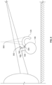
- FIG. 6 is a schematic illustration of the aircraft 100 of FIG. 5 showing the guide system 300 in the first position 302 of FIG. 3 .
- the crane 500 moves the thrust reverser portion 120 adjacent the pylon 108 to couple the thrust reverser portion 120 to the aircraft engine 106.
- the crane 500 moves (e.g., lowers) the thrust reverser portion 120 to couple the first guide system 304 and the second guide system 306.
- the crane 500 can be used to maneuver the thrust reverser portion 120 to enable the first arm connector 340 ( FIG. 3 ) to couple to the first leg connector 318 and the second arm connector 346 to couple to the second leg connector 320.
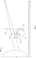
- FIG. 7 is a schematic illustration of the aircraft 100 of FIG. 5 showing the guide system 300 in the second position 400 of FIG. 4 .
- the thrust reverser portion 120 is moved via the crane 500 from the position of FIGS. 3 and 6 to the second position 400 of FIGS. 4 and 7 .
- the first arm 336 pivots relative to the first leg 310 via the first arm connector 340 and the first leg connector 318
- the second arm 344 pivots relative to the second leg 312 via the second arm connector 346 and the second leg connector 320.
- the guide system 300 guides the second hinge components 206 of the thrust reverser portion 120 into engagement and/or alignment with to the first hinge components 204 of the pylon 108. In other words, the guide system 300 aligns the hinge openings 210 and the hinge openings 208. Additionally, the guide system 300 maintains a position of the thrust reverser portion 120 fixed relative to the pylon 108 when the thrust reverser portion 120 is coupled to the crane 500. For example, when the second guide system 306 is coupled to the first guide system 304, the first guide system 304 stabilizes the thrust reverser portion 120 to prevent or restrict swaying or shifting (e.g.
- the guide system 300 prevents or restricts the thrust reverser portion 120 from swinging, moving, or shifting (e.g., swaying or rocking) relative to the pylon 108 when the guide system 300 in the second position 400.
- the hinge pins 212 can be coupled to the hinge openings 208 and the hinge openings 210 with the thrust reverser portion 120 fixed (e.g., in the fore-aft direction or side-to-side movement) relative to the pylon 108.
- the guide system 300 reduces or prevents the thrust reverser portion 120 from swaying or rocking (e.g., sideways, back-and-forth, etc.) when the hinge pins 212 are inserted into the hinge openings 208 and 210. After the hinge pins 212 have been installed, the guide system 300 is removed from the thrust reverser portion 120 and the pylon 108.
- swaying or rocking e.g., sideways, back-and-forth, etc.
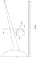
- FIG. 8 is a schematic illustration of the aircraft 100 of FIGS. 5-7 showing the thrust reverser portion 120 in an installed position 800.
- the thrust reverser portion 120 is rotated about the hinge pins 212 via the crane 500 to the installed position 800.
- the installed position 800 is representative of an installation angle or position of the thrust reverser portion 120 relative to the aircraft engine 106.
- the crane 500 is then decoupled from the thrust reverser portion 120.
- the guide system 300 was removed from the thrust reverser portion 120 and the pylon 108 prior to the moving the thrust reverser portion 120 to the installed position 800, in some examples, the guide system 300 can be removed from the thrust reverser portion 120 and/or the pylon 108 after the thrust reverser portion 120 is moved to the installed position 800.
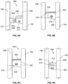
- FIGS. 9A-9D are partial, sectional views of the thrust reverser portion 120 relative to the pylon 108 as the guide system 300 moves between the first position 302 and the second position 400.
- FIG. 9A illustrates the thrust reverser portion 120 relative to the pylon 108 when the guide system 300 is in the first position 302 of FIG. 3 .
- the first one 350 of the second hinge components 206 of the thrust reverser portion 120 is aligned, but spaced apart from, the first one 314 of the first hinge components 204 of the pylon 108.
- the guide system 300 facilitates alignment between a first one 902 of the hinge openings 208 and a second one 904 of the hinge openings 210.
- FIG. 9A illustrates the thrust reverser portion 120 relative to the pylon 108 when the guide system 300 is in the first position 302 of FIG. 3 .
- the first one 350 of the second hinge components 206 of the thrust reverser portion 120 is aligned, but spaced apart from, the first one 314 of the first
- FIG. 9B illustrates the thrust reverser portion 120 relative to the pylon 108 when the guide system 300 is between the first position 302 and the second position 400.
- FIG. 9C illustrates the guide system 300 in the second position 400.
- the first one 314 of the first hinge components 204 is aligned with the first one 350 of the second hinge components 206 such that the first one 902 of the hinge openings 208 is aligned with the second one 904 of the hinge openings 210.
- the guide system 300 prevents swaying or movement (e.g., side-to-side movement) of the first one 350 of the second hinge components 206 relative to the first one 314 of the first hinge components 204 when the first arm 336 and the second arm 344 are in engagement with the first leg 310 and the second leg 312.
- FIG. 9D illustrates the hinge pin 212 coupled to the first one 902 of the hinge opening 208 and the second one 904 of the hinge opening 210 to pivotally couple the thrust reverser portion 120 and the pylon 108.
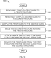
- FIG. 10 depicts an example flowchart representative of an example method 1000 to assemble structures of an aircraft using the example guide system 300 of FIG. 3 .
- the blocks can be re-arranged or removed, or additional blocks can be added.
- the method begins by removably coupling a first guide system 304 to a first structure (block 1002).
- the first guide system 304 can be removably coupled (e.g., removably fastened via fasteners) to the pylon 108.
- a second guide system 306 is removably coupled to a second structure (block 1004).
- the second guide system 306 is removably coupled (e.g., removably fastened via fasteners) to the thrust reverser portion 120.
- the second guide system 306 is coupled to the first guide system 304 (block 1006).
- the first arm 336 of the second guide system 306 aligns (e.g., couples to or attaches) with the first leg 310 of the first guide system 304 and the second arm 344 of the second guide system 306 aligns (e.g., couples to or attaches) with the second leg 312 of the first guide system 304.
- the first arm 336 is pivotally attached to the first leg 310 via the first arm connector 340 and the first leg connector 318
- the second arm 344 is pivotally attached to the second leg 312 via the second arm connector 346 and the second leg connector 320.
- the second structure is then moved relative to the first structure to align hinge openings of the respective first and second structures (block 1008).
- the thrust reverser portion 120 is pivoted relative to the pylon 108 such that the first arm 336 pivots relative to the first leg 310 and the second arm 344 pivots about the second leg 312 to align the hinge openings 208 of the pylon 108 with the hinge openings 210 of the thrust reverser portion 120.
- a hinge pin is attached to the respective hinge openings of the first structure and the second structure (block 1010).
- respective pairs of the hinge openings 208 and 210 in alignment receives the hinge pin 212 to couple the thrust reverser portion 120 and the pylon 108.
- the first guide system 304 is removed from the first structure and the second guide system 306 is removed from the second structure (block 1012).
- the thrust reverser portion 120 can be moved to the installed position 800.
- A, B, and/or C refers to any combination or subset of A, B, C such as (1) A alone, (2) B alone, (3) C alone, (4) A with B, (5) A with C, (6) B with C, and (7) A with B and with C.
- the phrase "at least one of A and B" is intended to refer to implementations including any of (1) at least one A, (2) at least one B, and (3) at least one A and at least one B.
- the phrase "at least one of A or B" is intended to refer to implementations including any of (1) at least one A, (2) at least one B, and (3) at least one A and at least one B.
Landscapes
- Engineering & Computer Science (AREA)
- Aviation & Aerospace Engineering (AREA)
- Mechanical Engineering (AREA)
- Chemical & Material Sciences (AREA)
- Combustion & Propulsion (AREA)
- Transportation (AREA)
- General Engineering & Computer Science (AREA)
- Manufacturing & Machinery (AREA)
- Pivots And Pivotal Connections (AREA)
Claims (13)
- Appareil (300) pour permettre l'alignement entre une section d'inverseur de poussée et un pylône d'un avion, l'appareil (300) comprenant:un premier système de guidage (304) structuré pour être couplé de manière amovible à une première structure d'avion (108) ayant un premier composant de charnière (204); etun deuxième système de guidage (306) structuré pour être couplé de manière amovible à une deuxième structure d'avion (120) ayant un deuxième composant de charnière (206), dans lequel le premier système de guidage (304) est configuré pour coopérer avec le deuxième système de guidage (306) de sorte que pendant l'utilisation, il permet l'alignement entre le premier composant de charnière (204) et le deuxième composant de charnière (206) pendant l'assemblage de la première structure d'avion (108) et de la deuxième structure d'avion (120), et dans lequel la première structure d'avion est un pylône (108) et la deuxième structure d'avion (120) est une section d'inverseur de poussée.
- Appareil selon la revendication 1, dans lequel le premier système de guidage inclut un corps (308), une première jambe (310) et une deuxième jambe (312), la première jambe (310) étant espacée de la deuxième jambe (312).
- Appareil selon la revendication 2, dans lequel la première jambe (310) et la deuxième jambe (312) sont fixées au corps (308).
- Appareil selon les revendications 2 ou 3, dans lequel le premier système de guidage (304) inclut un premier renfort (322) pour soutenir la première jambe (310) et un deuxième renfort (324) pour soutenir la deuxième jambe (312).
- Appareil selon la revendication 4, dans lequel le premier renfort (322) est couplé à la première jambe (310) et fait saillie dans une direction s'écartant de la première jambe (310), et dans lequel le deuxième renfort (324) est couplé à la deuxième jambe (312) et fait saillie dans une direction s'écartant de la deuxième jambe (312).
- Appareil selon l'une quelconque des revendications 2 à 5, dans lequel le deuxième système de guidage (306) inclut une première base (334) et un premier bras (336), le premier bras (336) faisant saillie depuis la première base (334).
- Appareil selon la revendication 6, dans lequel le deuxième système de guidage (306) inclut une deuxième base (342) et un deuxième bras (344), le deuxième bras (344) faisant saillie depuis la deuxième base (342).
- Appareil selon la revendication 7, dans lequel le premier bras (336) inclut un connecteur de premier bras (340) et la première jambe (310) inclut un connecteur de première jambe (318), le connecteur de premier bras (340) destiné à coopérer avec le connecteur de première jambe (318).
- Appareil selon l'invention 8, dans lequel le deuxième bras (344) inclut un connecteur de deuxième bras (346) et la deuxième jambe (312) inclut un connecteur de deuxième jambe (320), le connecteur de deuxième bras (346) destiné à coopérer avec le connecteur de deuxième jambe (320).
- Appareil selon la revendication 9, dans lequel le connecteur de premier bras (340) et le connecteur de première jambe (318) permettent au premier bras (336) de pivoter autour de la première jambe (310) lorsque le deuxième système de guidage (306) se déplace par rapport au premier système de guidage (304).
- Appareil selon la revendication 10, dans lequel le connecteur de deuxième bras (346) et le connecteur de deuxième jambe (320) permettent au deuxième bras (344) de pivoter autour de la deuxième jambe (312) lorsque le deuxième système de guidage (306) se déplace par rapport au premier système de guidage (304).
- Procédé pour installer une section d'inverseur de poussée sur un pylône (108) d'une structure d'avion, comprenant:le couplage de manière amovible d'un premier système de guidage (304) à une première structure (108) qui est le pylône;le couplage de manière amovible d'un deuxième système de guidage (306) à une deuxième structure (120) qui est la section d'inverseur de poussée;le couplage du premier système de guidage (304) et du deuxième système de guidage (306);le déplacement de la deuxième structure (120) vers la première structure (108);la fixation d'un axe de charnière (212) pour coupler la première structure (108) et la deuxième structure (120); etle retrait du premier système de guidage (304) de la première structure (108) et du deuxième système de guidage (306) de la deuxième structure (120).
- Procédé selon la revendication 12, dans lequel le déplacement de la deuxième structure (120) vers la première structure (108) inclut le pivotement du deuxième système de guidage (306) autour du premier système de guidage (304) d'une première position (302) à une deuxième position (400).
Applications Claiming Priority (1)
| Application Number | Priority Date | Filing Date | Title |
|---|---|---|---|
| US202163168806P | 2021-03-31 | 2021-03-31 |
Publications (2)
| Publication Number | Publication Date |
|---|---|
| EP4067239A1 EP4067239A1 (fr) | 2022-10-05 |
| EP4067239B1 true EP4067239B1 (fr) | 2024-07-24 |
Family
ID=80446090
Family Applications (1)
| Application Number | Title | Priority Date | Filing Date |
|---|---|---|---|
| EP22157732.3A Active EP4067239B1 (fr) | 2021-03-31 | 2022-02-21 | Systèmes de guidage pour installer des structures d'aéronef comme des inverseurs de poussée |
Country Status (3)
| Country | Link |
|---|---|
| US (1) | US12145742B2 (fr) |
| EP (1) | EP4067239B1 (fr) |
| CN (1) | CN115140312A (fr) |
Family Cites Families (38)
| Publication number | Priority date | Publication date | Assignee | Title |
|---|---|---|---|---|
| US2564530A (en) | 1946-11-14 | 1951-08-14 | Construction De Moteurs D Avia | Motor installation for aircraft |
| US5203525A (en) | 1991-10-23 | 1993-04-20 | Rohr, Inc. | Hinge with offset pivot line |
| US6189832B1 (en) | 1998-04-03 | 2001-02-20 | Hartwell Corporation | Permanently connected remote latch mechanism |
| US6604355B1 (en) | 2001-08-31 | 2003-08-12 | The Boeing Company | Thrust reverser hook latch system |
| US6860450B2 (en) * | 2002-12-23 | 2005-03-01 | The Boeing Company | Apparatus and method for folding helicopter rotor blades for storage and transport of helicopter |
| US8087145B2 (en) * | 2006-03-17 | 2012-01-03 | The Boeing Company | Alignment tool apparatus and method |
| US8511973B2 (en) | 2010-06-23 | 2013-08-20 | Rohr, Inc. | Guide system for nacelle assembly |
| FR2966555B1 (fr) | 2010-10-25 | 2013-08-16 | Lisi Aerospace Sas | Verrou a crochet muni d'un dispositif de positionnement et procede de montage d'un tel verrou |
| US9783315B2 (en) * | 2012-02-24 | 2017-10-10 | Rohr, Inc. | Nacelle with longitudinal translating cowling and rotatable sleeves |
| CN105579344B (zh) * | 2013-07-29 | 2017-10-13 | 庞巴迪公司 | 将预装配的动力装置和挂架总成附接到飞机的方法 |
| US9429138B2 (en) | 2013-08-09 | 2016-08-30 | Gamesa Innovation & Technology, S.L. | Apparatus, system and method for wind turbine component replacement |
| GB201506396D0 (en) * | 2014-12-11 | 2015-05-27 | Rolls Royce Plc | Cabin blower system |
| US10088167B2 (en) | 2015-06-15 | 2018-10-02 | General Electric Company | Combustion flow sleeve lifting tool |
| US9783313B2 (en) * | 2015-06-23 | 2017-10-10 | Rohr, Inc. | Installing or removing aircraft engines |
| JP6735217B2 (ja) * | 2016-12-05 | 2020-08-05 | 三菱航空機株式会社 | 航空機用のファイアシール構造および航空機 |
| FR3064980B1 (fr) * | 2017-04-05 | 2022-05-13 | Airbus Operations Sas | Systeme de propulsion d'un aeronef comportant une nacelle avec un systeme d'ouverture ameliore |
| FR3067004B1 (fr) * | 2017-05-30 | 2021-04-16 | Airbus Operations Sas | Systeme de propulsion d'un aeronef comportant une nacelle avec un systeme d'ouverture ameliore |
| US10822102B2 (en) * | 2017-06-16 | 2020-11-03 | Rohr, Inc. | Adjustable length beam between cowl hinges |
| US11267578B2 (en) * | 2017-06-19 | 2022-03-08 | Rohr, Inc. | Hinge assembly |
| FR3076323B1 (fr) * | 2017-12-28 | 2020-01-10 | Safran Nacelles | Inverseur de poussee a grilles pour turboreacteur |
| FR3079000A1 (fr) * | 2018-03-13 | 2019-09-20 | Airbus Operations | Turboreacteur double flux pour un aeronef avec une ouverture equipee d'une charniere avec ferrure en col de cygne |
| GB201808514D0 (en) * | 2018-05-24 | 2018-07-11 | Rolls Royce Plc | Mounting System and Mounting Method for Gas Turbine Aero Engine |
| FR3085702B1 (fr) | 2018-09-12 | 2022-05-20 | Airbus Operations Sas | Systeme de verrouillage d'un capot |
| US11077956B2 (en) * | 2018-11-07 | 2021-08-03 | Rohr, Inc | Pressure relief assembly |
| FR3089207A1 (fr) * | 2018-11-30 | 2020-06-05 | Airbus Operations | système de propulsion d’un aeronef comportant un capot mobile et articule |
| FR3090588B1 (fr) | 2018-12-21 | 2021-01-22 | Safran Aircraft Engines | Outillage pour placer un ensemble propulsif d’une position horizontale a une position verticale |
| FR3091520A1 (fr) * | 2019-01-09 | 2020-07-10 | Airbus Operations (S.A.S.) | Attache-moteur d’aéronef comprenant au moins un système d’immobilisation en translation d’un pion de cisaillement comportant une plaque d’obturation, procédé de montage de ladite attache-moteur et aéronef comprenant ladite attache-moteur |
| FR3094347A1 (fr) * | 2019-03-25 | 2020-10-02 | Airbus Operations (S.A.S.) | Attache moteur arrière d’un aéronef présentant des manilles en deux parties et aéronef comprenant au moins une telle attache moteur arrière |
| US11530623B2 (en) * | 2019-04-11 | 2022-12-20 | The Boeing Company | Systems and methods for positioning aircraft engine components |
| GB201909171D0 (en) * | 2019-06-26 | 2019-08-07 | Rolls Royce Plc | Gas turbine engine cowl doors |
| EP3798133B1 (fr) * | 2019-09-30 | 2023-06-21 | Rohr, Inc. | Liaison supportant une porte d'un système de propulsion d'aéronef |
| US20230255803A1 (en) * | 2019-10-05 | 2023-08-17 | Stumpworx Llc | Prosthetic devices, systems including the same, and related methods |
| US11548653B2 (en) * | 2019-10-08 | 2023-01-10 | Rohr, Inc. | Support structure for inner cowls of an aircraft propulsion system |
| FR3101675B1 (fr) * | 2019-10-08 | 2024-04-26 | Airbus Operations Sas | Ensemble de motorisation pour un aeronef comportant un inverseur de poussee manoeuvrable |
| EP3943737B1 (fr) * | 2020-04-07 | 2025-08-20 | Rohr, Inc. | Système inverseur de poussée à volet caché pour système de propulsion d'aéronef |
| DE102021201629A1 (de) | 2020-08-05 | 2022-02-10 | MTU Aero Engines AG | Abgasbehandlungsvorrichtung für ein flugtriebwerk |
| US12187445B2 (en) * | 2021-03-31 | 2025-01-07 | The Boeing Company | Guide systems for installing aircraft structures |
| CN217331619U (zh) * | 2022-02-15 | 2022-08-30 | 九江职业技术学院 | 一种航空发动机地面试车测试台 |
-
2022
- 2022-02-21 EP EP22157732.3A patent/EP4067239B1/fr active Active
- 2022-03-28 CN CN202210308884.1A patent/CN115140312A/zh active Pending
- 2022-03-30 US US17/709,050 patent/US12145742B2/en active Active
Also Published As
| Publication number | Publication date |
|---|---|
| EP4067239A1 (fr) | 2022-10-05 |
| US20220315241A1 (en) | 2022-10-06 |
| CN115140312A (zh) | 2022-10-04 |
| US12145742B2 (en) | 2024-11-19 |
Similar Documents
| Publication | Publication Date | Title |
|---|---|---|
| EP2060767B1 (fr) | Inverseur de poussée à porte pivotante pour un moteur à turbine à gaz de réacteur à double flux | |
| US5864922A (en) | Self centering hinge | |
| US4549708A (en) | Cowling latch system | |
| EP2330036B1 (fr) | Support de capot de ventilateur pour moteur de réacteur à double flux | |
| US12187445B2 (en) | Guide systems for installing aircraft structures | |
| US9505499B2 (en) | Methods and apparatus for supporting engines and nacelles relative to aircraft wings | |
| RU2323361C2 (ru) | Реверсор тяги турбореактивного двигателя | |
| US20180290694A1 (en) | Drag Reduction System | |
| EP4067239B1 (fr) | Systèmes de guidage pour installer des structures d'aéronef comme des inverseurs de poussée | |
| US20230286663A1 (en) | Propulsion assembly for an aircraft, comprising a load bearer | |
| US20250313348A1 (en) | Aircraft gantry system | |
| US8272595B2 (en) | Fan cowl support for a turbofan engine | |
| JPH07197851A (ja) | ターボジェットエンジンの推進力反転装置 | |
| US11697488B2 (en) | Radome cover shell and opening kinematic | |
| CN114728701B (zh) | 飞行器发动机机舱整流罩机构 | |
| US11022071B2 (en) | Load distribution panel assembly, system and method | |
| US9260193B2 (en) | Composite beam for turbojet engine nacelle support structure | |
| US20200164994A1 (en) | Aircraft nacelle comprising a cowl with two articulated doors | |
| EP4269232B1 (fr) | Système de fixation de carénage pour une aile d'un aéronef, aile d'aéronef et procédé de montage d'un dispositif de carénage | |
| EP4155214B1 (fr) | Kit de pièces pour former un ensemble de profil aérodynamique | |
| CN107074342B (zh) | 用于方向舵和升降舵应用的转折的翼梁 | |
| EP3878753B1 (fr) | Dispositif de verrouillage | |
| US20250389235A1 (en) | Thrust Reverser Mounting Assembly | |
| CN223116619U (zh) | 一种机翼运输装置、设备 | |
| US12448824B2 (en) | Panel assembly for a vehicle |
Legal Events
| Date | Code | Title | Description |
|---|---|---|---|
| PUAI | Public reference made under article 153(3) epc to a published international application that has entered the european phase |
Free format text: ORIGINAL CODE: 0009012 |
|
| STAA | Information on the status of an ep patent application or granted ep patent |
Free format text: STATUS: THE APPLICATION HAS BEEN PUBLISHED |
|
| AK | Designated contracting states |
Kind code of ref document: A1 Designated state(s): AL AT BE BG CH CY CZ DE DK EE ES FI FR GB GR HR HU IE IS IT LI LT LU LV MC MK MT NL NO PL PT RO RS SE SI SK SM TR |
|
| STAA | Information on the status of an ep patent application or granted ep patent |
Free format text: STATUS: REQUEST FOR EXAMINATION WAS MADE |
|
| 17P | Request for examination filed |
Effective date: 20230201 |
|
| RBV | Designated contracting states (corrected) |
Designated state(s): AL AT BE BG CH CY CZ DE DK EE ES FI FR GB GR HR HU IE IS IT LI LT LU LV MC MK MT NL NO PL PT RO RS SE SI SK SM TR |
|
| RAP3 | Party data changed (applicant data changed or rights of an application transferred) |
Owner name: THE BOEING COMPANY |
|
| GRAP | Despatch of communication of intention to grant a patent |
Free format text: ORIGINAL CODE: EPIDOSNIGR1 |
|
| STAA | Information on the status of an ep patent application or granted ep patent |
Free format text: STATUS: GRANT OF PATENT IS INTENDED |
|
| RIC1 | Information provided on ipc code assigned before grant |
Ipc: F02K 1/64 20060101ALI20240212BHEP Ipc: F02C 7/20 20060101ALI20240212BHEP Ipc: B64D 29/06 20060101ALI20240212BHEP Ipc: B64F 5/50 20170101ALI20240212BHEP Ipc: B64F 5/10 20170101AFI20240212BHEP |
|
| INTG | Intention to grant announced |
Effective date: 20240320 |
|
| GRAS | Grant fee paid |
Free format text: ORIGINAL CODE: EPIDOSNIGR3 |
|
| GRAA | (expected) grant |
Free format text: ORIGINAL CODE: 0009210 |
|
| STAA | Information on the status of an ep patent application or granted ep patent |
Free format text: STATUS: THE PATENT HAS BEEN GRANTED |
|
| P01 | Opt-out of the competence of the unified patent court (upc) registered |
Effective date: 20240528 |
|
| AK | Designated contracting states |
Kind code of ref document: B1 Designated state(s): AL AT BE BG CH CY CZ DE DK EE ES FI FR GB GR HR HU IE IS IT LI LT LU LV MC MK MT NL NO PL PT RO RS SE SI SK SM TR |
|
| REG | Reference to a national code |
Ref country code: GB Ref legal event code: FG4D |
|
| REG | Reference to a national code |
Ref country code: CH Ref legal event code: EP |
|
| REG | Reference to a national code |
Ref country code: IE Ref legal event code: FG4D Ref country code: DE Ref legal event code: R096 Ref document number: 602022004694 Country of ref document: DE |
|
| REG | Reference to a national code |
Ref country code: LT Ref legal event code: MG9D |
|
| REG | Reference to a national code |
Ref country code: NL Ref legal event code: MP Effective date: 20240724 |
|
| PG25 | Lapsed in a contracting state [announced via postgrant information from national office to epo] |
Ref country code: PT Free format text: LAPSE BECAUSE OF FAILURE TO SUBMIT A TRANSLATION OF THE DESCRIPTION OR TO PAY THE FEE WITHIN THE PRESCRIBED TIME-LIMIT Effective date: 20241125 |
|
| REG | Reference to a national code |
Ref country code: AT Ref legal event code: MK05 Ref document number: 1706107 Country of ref document: AT Kind code of ref document: T Effective date: 20240724 |
|
| PG25 | Lapsed in a contracting state [announced via postgrant information from national office to epo] |
Ref country code: NL Free format text: LAPSE BECAUSE OF FAILURE TO SUBMIT A TRANSLATION OF THE DESCRIPTION OR TO PAY THE FEE WITHIN THE PRESCRIBED TIME-LIMIT Effective date: 20240724 |
|
| PG25 | Lapsed in a contracting state [announced via postgrant information from national office to epo] |
Ref country code: PT Free format text: LAPSE BECAUSE OF FAILURE TO SUBMIT A TRANSLATION OF THE DESCRIPTION OR TO PAY THE FEE WITHIN THE PRESCRIBED TIME-LIMIT Effective date: 20241125 Ref country code: NL Free format text: LAPSE BECAUSE OF FAILURE TO SUBMIT A TRANSLATION OF THE DESCRIPTION OR TO PAY THE FEE WITHIN THE PRESCRIBED TIME-LIMIT Effective date: 20240724 |
|
| PG25 | Lapsed in a contracting state [announced via postgrant information from national office to epo] |
Ref country code: NO Free format text: LAPSE BECAUSE OF FAILURE TO SUBMIT A TRANSLATION OF THE DESCRIPTION OR TO PAY THE FEE WITHIN THE PRESCRIBED TIME-LIMIT Effective date: 20241024 |
|
| PG25 | Lapsed in a contracting state [announced via postgrant information from national office to epo] |
Ref country code: PL Free format text: LAPSE BECAUSE OF FAILURE TO SUBMIT A TRANSLATION OF THE DESCRIPTION OR TO PAY THE FEE WITHIN THE PRESCRIBED TIME-LIMIT Effective date: 20240724 Ref country code: GR Free format text: LAPSE BECAUSE OF FAILURE TO SUBMIT A TRANSLATION OF THE DESCRIPTION OR TO PAY THE FEE WITHIN THE PRESCRIBED TIME-LIMIT Effective date: 20241025 Ref country code: FI Free format text: LAPSE BECAUSE OF FAILURE TO SUBMIT A TRANSLATION OF THE DESCRIPTION OR TO PAY THE FEE WITHIN THE PRESCRIBED TIME-LIMIT Effective date: 20240724 |
|
| PG25 | Lapsed in a contracting state [announced via postgrant information from national office to epo] |
Ref country code: BG Free format text: LAPSE BECAUSE OF FAILURE TO SUBMIT A TRANSLATION OF THE DESCRIPTION OR TO PAY THE FEE WITHIN THE PRESCRIBED TIME-LIMIT Effective date: 20240724 |
|
| PG25 | Lapsed in a contracting state [announced via postgrant information from national office to epo] |
Ref country code: LV Free format text: LAPSE BECAUSE OF FAILURE TO SUBMIT A TRANSLATION OF THE DESCRIPTION OR TO PAY THE FEE WITHIN THE PRESCRIBED TIME-LIMIT Effective date: 20240724 |
|
| PG25 | Lapsed in a contracting state [announced via postgrant information from national office to epo] |
Ref country code: AT Free format text: LAPSE BECAUSE OF FAILURE TO SUBMIT A TRANSLATION OF THE DESCRIPTION OR TO PAY THE FEE WITHIN THE PRESCRIBED TIME-LIMIT Effective date: 20240724 Ref country code: IS Free format text: LAPSE BECAUSE OF FAILURE TO SUBMIT A TRANSLATION OF THE DESCRIPTION OR TO PAY THE FEE WITHIN THE PRESCRIBED TIME-LIMIT Effective date: 20241124 |
|
| PG25 | Lapsed in a contracting state [announced via postgrant information from national office to epo] |
Ref country code: HR Free format text: LAPSE BECAUSE OF FAILURE TO SUBMIT A TRANSLATION OF THE DESCRIPTION OR TO PAY THE FEE WITHIN THE PRESCRIBED TIME-LIMIT Effective date: 20240724 |
|
| PG25 | Lapsed in a contracting state [announced via postgrant information from national office to epo] |
Ref country code: ES Free format text: LAPSE BECAUSE OF FAILURE TO SUBMIT A TRANSLATION OF THE DESCRIPTION OR TO PAY THE FEE WITHIN THE PRESCRIBED TIME-LIMIT Effective date: 20240724 Ref country code: RS Free format text: LAPSE BECAUSE OF FAILURE TO SUBMIT A TRANSLATION OF THE DESCRIPTION OR TO PAY THE FEE WITHIN THE PRESCRIBED TIME-LIMIT Effective date: 20241024 |
|
| PG25 | Lapsed in a contracting state [announced via postgrant information from national office to epo] |
Ref country code: RS Free format text: LAPSE BECAUSE OF FAILURE TO SUBMIT A TRANSLATION OF THE DESCRIPTION OR TO PAY THE FEE WITHIN THE PRESCRIBED TIME-LIMIT Effective date: 20241024 Ref country code: PL Free format text: LAPSE BECAUSE OF FAILURE TO SUBMIT A TRANSLATION OF THE DESCRIPTION OR TO PAY THE FEE WITHIN THE PRESCRIBED TIME-LIMIT Effective date: 20240724 Ref country code: NO Free format text: LAPSE BECAUSE OF FAILURE TO SUBMIT A TRANSLATION OF THE DESCRIPTION OR TO PAY THE FEE WITHIN THE PRESCRIBED TIME-LIMIT Effective date: 20241024 Ref country code: LV Free format text: LAPSE BECAUSE OF FAILURE TO SUBMIT A TRANSLATION OF THE DESCRIPTION OR TO PAY THE FEE WITHIN THE PRESCRIBED TIME-LIMIT Effective date: 20240724 Ref country code: IS Free format text: LAPSE BECAUSE OF FAILURE TO SUBMIT A TRANSLATION OF THE DESCRIPTION OR TO PAY THE FEE WITHIN THE PRESCRIBED TIME-LIMIT Effective date: 20241124 Ref country code: HR Free format text: LAPSE BECAUSE OF FAILURE TO SUBMIT A TRANSLATION OF THE DESCRIPTION OR TO PAY THE FEE WITHIN THE PRESCRIBED TIME-LIMIT Effective date: 20240724 Ref country code: GR Free format text: LAPSE BECAUSE OF FAILURE TO SUBMIT A TRANSLATION OF THE DESCRIPTION OR TO PAY THE FEE WITHIN THE PRESCRIBED TIME-LIMIT Effective date: 20241025 Ref country code: FI Free format text: LAPSE BECAUSE OF FAILURE TO SUBMIT A TRANSLATION OF THE DESCRIPTION OR TO PAY THE FEE WITHIN THE PRESCRIBED TIME-LIMIT Effective date: 20240724 Ref country code: ES Free format text: LAPSE BECAUSE OF FAILURE TO SUBMIT A TRANSLATION OF THE DESCRIPTION OR TO PAY THE FEE WITHIN THE PRESCRIBED TIME-LIMIT Effective date: 20240724 Ref country code: BG Free format text: LAPSE BECAUSE OF FAILURE TO SUBMIT A TRANSLATION OF THE DESCRIPTION OR TO PAY THE FEE WITHIN THE PRESCRIBED TIME-LIMIT Effective date: 20240724 Ref country code: AT Free format text: LAPSE BECAUSE OF FAILURE TO SUBMIT A TRANSLATION OF THE DESCRIPTION OR TO PAY THE FEE WITHIN THE PRESCRIBED TIME-LIMIT Effective date: 20240724 |
|
| PG25 | Lapsed in a contracting state [announced via postgrant information from national office to epo] |
Ref country code: DK Free format text: LAPSE BECAUSE OF FAILURE TO SUBMIT A TRANSLATION OF THE DESCRIPTION OR TO PAY THE FEE WITHIN THE PRESCRIBED TIME-LIMIT Effective date: 20240724 Ref country code: SM Free format text: LAPSE BECAUSE OF FAILURE TO SUBMIT A TRANSLATION OF THE DESCRIPTION OR TO PAY THE FEE WITHIN THE PRESCRIBED TIME-LIMIT Effective date: 20240724 Ref country code: RO Free format text: LAPSE BECAUSE OF FAILURE TO SUBMIT A TRANSLATION OF THE DESCRIPTION OR TO PAY THE FEE WITHIN THE PRESCRIBED TIME-LIMIT Effective date: 20240724 |
|
| PG25 | Lapsed in a contracting state [announced via postgrant information from national office to epo] |
Ref country code: EE Free format text: LAPSE BECAUSE OF FAILURE TO SUBMIT A TRANSLATION OF THE DESCRIPTION OR TO PAY THE FEE WITHIN THE PRESCRIBED TIME-LIMIT Effective date: 20240724 |
|
| PG25 | Lapsed in a contracting state [announced via postgrant information from national office to epo] |
Ref country code: CZ Free format text: LAPSE BECAUSE OF FAILURE TO SUBMIT A TRANSLATION OF THE DESCRIPTION OR TO PAY THE FEE WITHIN THE PRESCRIBED TIME-LIMIT Effective date: 20240724 |
|
| REG | Reference to a national code |
Ref country code: DE Ref legal event code: R097 Ref document number: 602022004694 Country of ref document: DE |
|
| PG25 | Lapsed in a contracting state [announced via postgrant information from national office to epo] |
Ref country code: SK Free format text: LAPSE BECAUSE OF FAILURE TO SUBMIT A TRANSLATION OF THE DESCRIPTION OR TO PAY THE FEE WITHIN THE PRESCRIBED TIME-LIMIT Effective date: 20240724 Ref country code: IT Free format text: LAPSE BECAUSE OF FAILURE TO SUBMIT A TRANSLATION OF THE DESCRIPTION OR TO PAY THE FEE WITHIN THE PRESCRIBED TIME-LIMIT Effective date: 20240724 |
|
| PLBE | No opposition filed within time limit |
Free format text: ORIGINAL CODE: 0009261 |
|
| STAA | Information on the status of an ep patent application or granted ep patent |
Free format text: STATUS: NO OPPOSITION FILED WITHIN TIME LIMIT |
|
| 26N | No opposition filed |
Effective date: 20250425 |
|
| PG25 | Lapsed in a contracting state [announced via postgrant information from national office to epo] |
Ref country code: SE Free format text: LAPSE BECAUSE OF FAILURE TO SUBMIT A TRANSLATION OF THE DESCRIPTION OR TO PAY THE FEE WITHIN THE PRESCRIBED TIME-LIMIT Effective date: 20240724 |
|
| PG25 | Lapsed in a contracting state [announced via postgrant information from national office to epo] |
Ref country code: MC Free format text: LAPSE BECAUSE OF FAILURE TO SUBMIT A TRANSLATION OF THE DESCRIPTION OR TO PAY THE FEE WITHIN THE PRESCRIBED TIME-LIMIT Effective date: 20240724 |
|
| REG | Reference to a national code |
Ref country code: CH Ref legal event code: PL |
|
| PG25 | Lapsed in a contracting state [announced via postgrant information from national office to epo] |
Ref country code: LU Free format text: LAPSE BECAUSE OF NON-PAYMENT OF DUE FEES Effective date: 20250221 |
|
| PG25 | Lapsed in a contracting state [announced via postgrant information from national office to epo] |
Ref country code: CH Free format text: LAPSE BECAUSE OF NON-PAYMENT OF DUE FEES Effective date: 20250228 |
|
| REG | Reference to a national code |
Ref country code: BE Ref legal event code: MM Effective date: 20250228 |
|
| PG25 | Lapsed in a contracting state [announced via postgrant information from national office to epo] |
Ref country code: BE Free format text: LAPSE BECAUSE OF NON-PAYMENT OF DUE FEES Effective date: 20250228 |
|
| PG25 | Lapsed in a contracting state [announced via postgrant information from national office to epo] |
Ref country code: IE Free format text: LAPSE BECAUSE OF NON-PAYMENT OF DUE FEES Effective date: 20250221 |
|
| PGFP | Annual fee paid to national office [announced via postgrant information from national office to epo] |
Ref country code: GB Payment date: 20260227 Year of fee payment: 5 |
|
| PGFP | Annual fee paid to national office [announced via postgrant information from national office to epo] |
Ref country code: DE Payment date: 20260227 Year of fee payment: 5 |
|
| PGFP | Annual fee paid to national office [announced via postgrant information from national office to epo] |
Ref country code: FR Payment date: 20260225 Year of fee payment: 5 |