EP4066972A1 - Rotary cutting tool - Google Patents
Rotary cutting tool Download PDFInfo
- Publication number
- EP4066972A1 EP4066972A1 EP20941778.1A EP20941778A EP4066972A1 EP 4066972 A1 EP4066972 A1 EP 4066972A1 EP 20941778 A EP20941778 A EP 20941778A EP 4066972 A1 EP4066972 A1 EP 4066972A1
- Authority
- EP
- European Patent Office
- Prior art keywords
- straight line
- line portion
- angle
- rotary cutting
- cutting tool
- Prior art date
- Legal status (The legal status is an assumption and is not a legal conclusion. Google has not performed a legal analysis and makes no representation as to the accuracy of the status listed.)
- Granted
Links
Images



Classifications
-
- B—PERFORMING OPERATIONS; TRANSPORTING
- B23—MACHINE TOOLS; METAL-WORKING NOT OTHERWISE PROVIDED FOR
- B23C—MILLING
- B23C5/00—Milling-cutters
- B23C5/02—Milling-cutters characterised by the shape of the cutter
- B23C5/10—Shank-type cutters, i.e. with an integral shaft
-
- B—PERFORMING OPERATIONS; TRANSPORTING
- B23—MACHINE TOOLS; METAL-WORKING NOT OTHERWISE PROVIDED FOR
- B23B—TURNING; BORING
- B23B51/00—Tools for drilling machines
-
- B—PERFORMING OPERATIONS; TRANSPORTING
- B23—MACHINE TOOLS; METAL-WORKING NOT OTHERWISE PROVIDED FOR
- B23B—TURNING; BORING
- B23B2250/00—Compensating adverse effects during turning, boring or drilling
- B23B2250/12—Cooling and lubrication
-
- B—PERFORMING OPERATIONS; TRANSPORTING
- B23—MACHINE TOOLS; METAL-WORKING NOT OTHERWISE PROVIDED FOR
- B23B—TURNING; BORING
- B23B2251/00—Details of tools for drilling machines
- B23B2251/14—Configuration of the cutting part, i.e. the main cutting edges
-
- B—PERFORMING OPERATIONS; TRANSPORTING
- B23—MACHINE TOOLS; METAL-WORKING NOT OTHERWISE PROVIDED FOR
- B23C—MILLING
- B23C2210/00—Details of milling cutters
- B23C2210/32—Details of teeth
- B23C2210/321—Lands, i.e. the area on the rake face in the immediate vicinity of the cutting edge
-
- B—PERFORMING OPERATIONS; TRANSPORTING
- B23—MACHINE TOOLS; METAL-WORKING NOT OTHERWISE PROVIDED FOR
- B23C—MILLING
- B23C2210/00—Details of milling cutters
- B23C2210/40—Flutes, i.e. chip conveying grooves
-
- B—PERFORMING OPERATIONS; TRANSPORTING
- B23—MACHINE TOOLS; METAL-WORKING NOT OTHERWISE PROVIDED FOR
- B23C—MILLING
- B23C2210/00—Details of milling cutters
- B23C2210/54—Configuration of the cutting part
-
- B—PERFORMING OPERATIONS; TRANSPORTING
- B23—MACHINE TOOLS; METAL-WORKING NOT OTHERWISE PROVIDED FOR
- B23C—MILLING
- B23C2250/00—Compensating adverse effects during milling
- B23C2250/12—Cooling and lubrication
Definitions
- the present disclosure relates to a rotary cutting tool.
- Japanese Patent Laying-Open No. 2017-159380 discloses an end mill having a rake face in which a plurality of streaks (recesses) are formed.
- PTL 1 Japanese Patent Laying-Open No. 2017-159380
- a rotary cutting tool is rotatable about an axial line and includes a rake face and a flank face.
- the flank face is contiguous to the rake face.
- a ridgeline between the rake face and the flank face constitutes a cutting edge.
- the rake face is constituted of a plurality of straight line portions.
- a rotary cutting tool to suppress breakage of a cutting edge.
- the present embodiment will be described in detail with reference to figures. It should be noted that in the below-described figures, the same or corresponding portions are denoted by the same reference characters, and will not be described repeatedly.
- Fig. 1 is a schematic perspective view showing a configuration of a rotary cutting tool 100 according to the present embodiment.
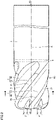
- Fig. 2 is a schematic side view showing the configuration of rotary cutting tool 100 according to the present embodiment.
- rotary cutting tool 100 according to the present embodiment is, for example, an end mill, and is constituted of a cutting edge portion 90, a joint portion 8, and a shank portion 3.
- Cutting edge portion 90 has first rake faces 10, first flank faces 31, second rake faces 15, second flank faces 33, outer peripheral cutting edges 20, bottom cutting edges 21, and a front end 58.
- Shank portion 3 has a rear end 59.
- Cutting edge portion 90 is fixed to shank portion 3 by joint portion 8.
- Joint portion 8 is a brazing material. Joint portion 8 is located between cutting edge portion 90 and shank portion 3.
- Rotary cutting tool 100 is rotatable about an axial line A. From another viewpoint, it can be said that axial line A is a rotation axis of rotary cutting tool 100.
- a material of cutting edge portion 90 includes a cubic boron nitride (cBN) sintered material, for example.
- the material of cutting edge portion 90 may include diamond.
- the diamond may be a single-crystal diamond or a polycrystalline diamond.
- Shank portion 3 includes a cemented carbide, for example.
- the cemented carbide is, for example, a tungsten carbide (WC)-based cemented carbide, a cemented carbide including Co in addition to WC, or a cemented carbide having a carbonitride of Cr, Ti, Ta, Nb, or the like added therein in addition to WC.
- WC tungsten carbide
- Front end 58 of rotary cutting tool 100 is a portion to face a workpiece.
- Rear end 59 of rotary cutting tool 100 is a portion to face a tool for rotating rotary cutting tool 100.
- Shank portion 3 is a portion to be attached to the tool for rotating rotary cutting tool 100.
- a direction along axial line A is an axial direction.
- a direction perpendicular to the axial direction is a radial direction.
- a direction from front end 58 toward rear end 59 is referred to as "rearward in the axial direction”.
- a direction from rear end 59 toward front end 58 is referred to as "forward in the axial direction”.
- each of first flank faces 31 is contiguous to a corresponding one of first rake faces 10.
- a ridgeline between first rake face 10 and first flank face 31 constitutes outer peripheral cutting edge 20.
- Each of second flank faces 33 is contiguous to a corresponding one of second rake faces 15.
- a ridgeline between second rake face 15 and second flank face 33 constitutes bottom cutting edge 21.
- First rake face 10 is contiguous to second rake face 15.
- First rake face 10 is located rearward in the axial direction with respect to second rake face 15.
- First flank face 31 is contiguous to second flank face 33.
- First flank face 31 is located rearward in the axial direction with respect to second flank face 33.
- First swarf discharging flutes 1 and second swarf discharging flutes 2 are formed in cutting edge portion 90 of rotary cutting tool 100.
- Each of first swarf discharging flutes 1 is constituted of first rake face 10 and a first swarf discharging surface 40.
- Each of second swarf discharging flutes 2 is constituted of second rake face 15 and a second swarf discharging surface 45.
- Second swarf discharging surface 45 is contiguous to first swarf discharging surface 40.
- First swarf discharging flute 1 is provided helically around axial line A.
- Second swarf discharging flute 2 is contiguous to first swarf discharging flute 1. In the direction along axial line A, the length of first swarf discharging flute 1 is longer than the length of second swarf discharging flute 2.
- Rotary cutting tool 100 is, for example, a multi-edged tool.
- the number of outer peripheral cutting edges 20 is, for example, more than or equal to 2.
- the lower limit of the number of outer peripheral cutting edges 20 is not particularly limited, and may be, for example, more than or equal to 4, or more than or equal to 8.
- the upper limit of the number of outer peripheral cutting edges 20 is not particularly limited, and may be, for example, less than or equal to 20, or less than or equal to 16.
- the number of outer peripheral cutting edges 20 is 5.
- the number of bottom cutting edges 21 may be the same as the number of outer peripheral cutting edges 20.
- Fig. 3 is a schematic cross sectional view when viewed along a line III-III of Fig. 2 .
- the cross section is a cross section perpendicular to the axial line.
- the plurality of first swarf discharging flutes 1 are disposed in a peripheral direction (rotation direction R).
- the plurality of first flank faces 31 are disposed in the peripheral direction.
- the plurality of outer peripheral cutting edges 20 are disposed in the peripheral direction. That is, when a combination of a first flank face 31, a first swarf discharging flute 1, and an outer peripheral cutting edge 20 is assumed as one cutting component, a plurality of cutting components are disposed in the peripheral direction.
- first swarf discharging flute 1 is located forward in the rotation direction with respect to first flank face 31.
- first rake face 10 is located forward in the rotation direction with respect to outer peripheral cutting edge 20.
- first swarf discharging surface 40 is located forward in the rotation direction with respect to first rake face 10.
- first flank faces 31 and first swarf discharging flutes 1 are alternately located in rotation direction R.
- One end of each first flank face 31 constitutes outer peripheral cutting edge 20.
- the other end of first flank face 31 constitutes a tail portion 5.
- First flank face 31 is contiguous to first rake face 10 at outer peripheral cutting edge 20.
- First flank face 31 is contiguous to first swarf discharging surface 40 at tail portion 5.
- a length (first length L1) from axial line A to outer peripheral cutting edge 20 is longer than a length (second length L2) from axial line A to tail portion 5.
- first rake face 10 is constituted of a plurality of straight line portions.
- the plurality of straight line portions include a first straight line portion 11, a second straight line portion 12, a third straight line portion 13, and a fourth straight line portion 14.
- First straight line portion 11 is contiguous to first flank face 31.
- First straight line portion 11 is inclined with respect to first flank face 31.
- a boundary between first straight line portion 11 and first flank face 31 is outer peripheral cutting edge 20.
- Second straight line portion 12 is inclined with respect to first straight line portion 11.
- Second straight line portion 12 is contiguous to first straight line portion 11.
- Second straight line portion 12 is located opposite to first flank face 31 with respect to first straight line portion 11. From another viewpoint, it can be said that first straight line portion 11 is located between second straight line portion 12 and first flank face 31.
- Third straight line portion 13 is inclined with respect to second straight line portion 12.
- Third straight line portion 13 is contiguous to second straight line portion 12.
- Third straight line portion 13 is located opposite to first straight line portion 11 with respect to second straight line portion 12. From another viewpoint, it can be said that second straight line portion 12 is located between third straight line portion 13 and first straight line portion 11.
- Fourth straight line portion 14 is inclined with respect to third straight line portion 13.
- Fourth straight line portion 14 is contiguous to third straight line portion 13.
- Fourth straight line portion 14 is located opposite to second straight line portion 12 with respect to third straight line portion 13. From another viewpoint, it can be said that third straight line portion 13 is located between fourth straight line portion 14 and second straight line portion 12.
- first angle ⁇ 1 formed by first straight line portion 11 and second straight line portion 12 may be more than a second angle ⁇ 2 formed by second straight line portion 12 and third straight line portion 13.
- Second angle ⁇ 2 formed by second straight line portion 12 and third straight line portion 13 may be more than a third angle ⁇ 3 formed by third straight line portion 13 and fourth straight line portion 14.
- First angle ⁇ 1 is more than or equal to 140° and less than 180°, for example.
- the lower limit of first angle ⁇ 1 is not particularly limited, and may be more than or equal to 150° or may be more than or equal to 160°, for example.
- the upper limit of first angle ⁇ 1 is not particularly limited, and may be less than or equal to 178° or may be less than or equal to 175°, for example.
- a boundary between first straight line portion 11 and second straight line portion 12 is a first position X 1 .
- a boundary between second straight line portion 12 and third straight line portion 13 is a second position X 2 .
- a boundary between third straight line portion 13 and fourth straight line portion 14 is a third position X 3 .
- the length of first straight line portion 11 (distance in a straight line between outer peripheral cutting edge 20 and first position X 1 ) may be larger than the length of second straight line portion 12 (distance in a straight line between first position X 1 and second position X 2 ).
- the length of second straight line portion 12 (distance in a straight line between first position X 1 and second position X 2 ) may be larger than the length of third straight line portion 13 (distance in a straight line between second position X 2 and third position X3).
- a distance (first distance a1) between outer peripheral cutting edge 20 and first position X 1 may be the same as a distance (second distance a2) between first position X 1 and second position X 2 .
- the distance (second distance a2) between first position X 1 and second position X 2 may be the same as a distance (third distance a3) between second position X 2 and third position X 3 .
- first swarf discharging surface 40 may be constituted of, for example, a plurality of straight line portions.
- First swarf discharging surface 40 has, for example, a fifth straight line portion 41, a sixth straight line portion 42, a seventh straight line portion 43, and an eighth straight line portion 44.
- Fifth straight line portion 41 is inclined with respect to first flank face 31.
- Fifth straight line portion 41 is contiguous to tail portion 5.
- Sixth straight line portion 42 is inclined with respect to fifth straight line portion 41.
- Sixth straight line portion 42 is contiguous to fifth straight line portion 41.
- Sixth straight line portion 42 is located opposite to tail portion 5 with respect to fifth straight line portion 41. From another viewpoint, it can be said that fifth straight line portion 41 is located between sixth straight line portion 42 and tail portion 5.
- Seventh straight line portion 43 is inclined with respect to sixth straight line portion 42.
- Seventh straight line portion 43 is contiguous to sixth straight line portion 42.
- Seventh straight line portion 43 is located opposite to fifth straight line portion 41 with respect to sixth straight line portion 42.
- sixth straight line portion 42 is located between seventh straight line portion 43 and fifth straight line portion 41.
- Eighth straight line portion 44 is inclined with respect to seventh straight line portion 43.
- Eighth straight line portion 44 is contiguous to seventh straight line portion 43.
- Eighth straight line portion 44 is located opposite to sixth straight line portion 42 with respect to seventh straight line portion 43. From another viewpoint, it can be said that seventh straight line portion 43 is located between eighth straight line portion 44 and sixth straight line portion 42.
- a fourth angle ⁇ n-1 formed by fifth straight line portion 41 and sixth straight line portion 42 may be more than a fifth angle ⁇ n-2 formed by sixth straight line portion 42 and seventh straight line portion 43.
- Fifth angle ⁇ n-2 formed by sixth straight line portion 42 and seventh straight line portion 43 may be more than a sixth angle ⁇ n-3 formed by seventh straight line portion 43 and eighth straight line portion 44.
- a boundary between fifth straight line portion 41 and sixth straight line portion 42 is a fourth position X n-1 .
- a boundary between sixth straight line portion 42 and seventh straight line portion 43 is a fifth position X n-2 .
- a boundary between seventh straight line portion 43 and eighth straight line portion 44 is a sixth position X n-3 .
- the length of fifth straight line portion 41 (distance in a straight line between tail portion 5 and fourth position X n-1 ) may be larger than the length of sixth straight line portion 42 (distance in a straight line between fourth position X n-1 and fifth position Xn-2).
- sixth straight line portion 42 (distance in a straight line between fourth position X n-1 and fifth position X n-2 ) may be larger than the length of seventh straight line portion 43 (distance in a straight line between fifth position X n-2 and sixth position Xn-3).
- a distance (fourth distance b1) between tail portion 5 and fourth position X n-1 may be the same as a distance (fifth distance b2) between fourth position X n-1 and fifth position X n-2 .
- the distance (fifth distance b2) between fourth position X n-1 and fifth position X n-2 may be the same as a distance (sixth distance b3) between fifth position X n-2 and sixth position X n-3 .
- Fig. 6 is a diagram showing a relation between the angle formed by two adjacent straight line portions and the position in the first swarf discharging flute.
- first rake face 10 the angle formed by two adjacent straight line portions may be monotonously decreased in the direction from outer peripheral cutting edge 20 toward first swarf discharging surface 40.
- rake face 10 may be constituted of, for example, more than or equal to 5 straight line portions.
- first swarf discharging surface 40 the angle formed by two adjacent straight line portions may be monotonously decreased in the direction from tail portion 5 toward first rake face 10.
- first swarf discharging surface 40 may be constituted of, for example, more than or equal to 5 straight line portions.
- the surface of first swarf discharging flute 1 may be constituted of a plurality of straight line portions.
- the lower limit of the number of the straight line portions is not particularly limited, and may be more than or equal to 10 or may be more than or equal to 20, for example.
- the upper limit of the number of the straight line portions is not particularly limited, and may be less than or equal to 50 or may be less than or equal to 40, for example.
- a difference (angle difference B) between the maximum value of the angle formed by two adjacent straight line portions and the minimum value of the angle formed by two adjacent straight line portions is, for example, more than or equal to 8°.
- the lower limit of angle difference B is not particularly limited, and may be more than or equal to 10° or may be more than or equal to 12°, for example.
- the upper limit of angle difference B is not particularly limited, and may be less than or equal to 30°, for example.
- Rotary cutting tool 100 is, for example, an end mill, but is not limited to the end mill.
- Rotary cutting tool 100 may be, for example, a reamer, a drill, or a tap.
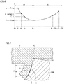
- Fig. 7 is a schematic cross sectional view showing a state in which cutting is performed using rotary cutting tool 100 according to the present embodiment.
- swarf 61 of a workpiece 60 cut by cutting edge 20 of rotary cutting tool 100 is discharged with swarf 61 being in contact with rake face 10.
- swarf 61 may be melted and adhered to rake face 10. The melting and adhesion of swarf 61 may lead to breakage of cutting edge 20.
- rake face 10 is constituted of the plurality of straight line portions. Specifically, in the cross section perpendicular to axial line A, rake face 10 has first straight line portion 11, second straight line portion 12, and third straight line portion 13, second straight line portion 12 being inclined with respect to first straight line portion 11, second straight line portion 12 being contiguous to first straight line portion 11, third straight line portion 13 being inclined with respect to second straight line portion 12, third straight line portion 13 being contiguous to second straight line portion 12.
- swarf 61 is moved on rake face 10
- swarf 61 is curled at a certain curvature.
- a space 9 is formed between curled swarf 61 and the boundary between first straight line portion 11 and second straight line portion 12.
- a space 9 is formed between curled swarf 61 and the boundary between second straight line portion 12 and third straight line portion 13.
- Rotary cutting tools 100 of samples 1 to 8 were prepared.
- Rotary cutting tools 100 of samples 1 to 6 are end mills according to examples of the present disclosure.
- Rotary cutting tool 100 of sample 8 is an end mill according to a comparative example.
- a cBN sintered material is brazed to the tip of the shank portion composed of cemented carbide.
- a plurality of straight line portions are formed in the surface of the swarf discharging flute provided helically in the cBN sintered material.
- the plurality of straight line portions are formed by performing a finishing process onto the surface (rake face) of the swarf discharging flute using a grindstone provided with straight line portions. The process is performed multiple times while changing the angle of the grindstone.
- the surface (rake face) of the swarf discharging flute is curved.
- the number of the straight line portions in first swarf discharging flute 1 was 5.
- the maximum value of the angle formed by two adjacent straight line portions was 178°.
- the minimum value of the angle formed by two adjacent straight line portions was 151°.
- a difference between the maximum value of the angle and the minimum value of the angle was 27°.
- the number of the straight line portions in first swarf discharging flute 1 was 10.
- the maximum value of the angle formed by two adjacent straight line portions was 178°.
- the minimum value of the angle formed by two adjacent straight line portions was 155°.
- a difference between the maximum value of the angle and the minimum value of the angle was 23°.
- the number of the straight line portions in first swarf discharging flute 1 was 20.
- the maximum value of the angle formed by two adjacent straight line portions was 178°.
- the minimum value of the angle formed by two adjacent straight line portions was 162°.
- a difference between the maximum value of the angle and the minimum value of the angle was 16°.
- the number of the straight line portions in first swarf discharging flute 1 was 30.
- the maximum value of the angle formed by two adjacent straight line portions was 178°.
- the minimum value of the angle formed by two adjacent straight line portions was 168°.
- a difference between the maximum value of the angle and the minimum value of the angle was 10°.
- the number of the straight line portions in first swarf discharging flute 1 was 10.
- the maximum value of the angle formed by two adjacent straight line portions was 175°.
- the minimum value of the angle formed by two adjacent straight line portions was 163°.
- a difference between the maximum value of the angle and the minimum value of the angle was 12°.
- the number of the straight line portions in first swarf discharging flute 1 was 10.
- the maximum value of the angle formed by two adjacent straight line portions was 175°.
- the minimum value of the angle formed by two adjacent straight line portions was 167°.
- a difference between the maximum value of the angle and the minimum value of the angle was 8°.
- the number of the straight line portions in first swarf discharging flute 1 was 40.
- the maximum value of the angle formed by two adjacent straight line portions was 176°.
- the minimum value of the angle formed by two adjacent straight line portions was 171°.
- a difference between the maximum value of the angle and the minimum value of the angle was 5°.
- workpieces 60 were processed using respective rotary cutting tools 100 of samples 1 to 8 (see Fig. 7 ).
- Each of workpieces 60 was Ti-6A1-4V.
- a cutting speed (Vc) was set to 300 m/min.
- a feed amount (f) was set to 0.01 mm/cutting edge.
- a cut amount (Ae) in the lateral direction was set to 0.1 mm.
- a cut amount (Ap) in the axial direction was set to 0.5 mm.
- Coolant was an emulsion diluted by 20 times.
- Table 1 shows tool lives when workpieces 60 were processed using respective rotary cutting tools 100 of samples 1 to 8. Each of the tool lives represents a period of time from the start of the processing until breakage of the cutting edge. As shown in Table 1, each of the tool lives when workpieces 60 were processed using rotary cutting tools 100 of samples 1 to 7 was more than or equal to 20 minutes and less than or equal to 50 minutes. On the other hand, the tool life when workpiece 60 was processed using rotary cutting tool 100 of sample 8 was 10 minutes. In view of the above results, it was proved that breakage of the cutting edge can be suppressed when rake face 10 is constituted of the plurality of straight line portions in the cross section perpendicular to axial line A. Also, it was proved that breakage of the cutting edge can be further suppressed when the difference between the maximum value and minimum value of the angle formed by two adjacent straight line portions is more than or equal to 8°.
- first swarf discharging flute 2: second swarf discharging flute; 3: shank portion; 5: tail portion; 8: joint portion; 9: space; 10: first rake face (rake face); 11: first straight line portion; 12: second straight line portion; 13: third straight line portion; 14: fourth straight line portion; 15: second rake face; 20: cutting edge (outer peripheral cutting edge); 21: bottom cutting edge; 31 first flank face (flank face); 33: second flank face; 40: first swarf discharging surface; 41: fifth straight line portion; 42: sixth straight line portion; 43: seventh straight line portion; 44: eighth straight line portion; 45: second swarf discharging surface; 58: front end; 59: rear end; 60: workpiece; 61: swarf; 90: cutting edge portion; 100: rotary cutting tool; A: axial line; B: angle difference; L1: first length; L2: second length; R: rotation direction; X 1 : first position; X 2
Landscapes
- Engineering & Computer Science (AREA)
- Mechanical Engineering (AREA)
- Milling Processes (AREA)
- Drilling Tools (AREA)
Abstract
Description
- The present disclosure relates to a rotary cutting tool.
-
Japanese Patent Laying-Open No. 2017-159380 - PTL 1:
Japanese Patent Laying-Open No. 2017-159380 - A rotary cutting tool according to the present disclosure is rotatable about an axial line and includes a rake face and a flank face. The flank face is contiguous to the rake face. A ridgeline between the rake face and the flank face constitutes a cutting edge. In a cross section perpendicular to the axial line, the rake face is constituted of a plurality of straight line portions.
-
-
Fig. 1 is a schematic perspective view showing a configuration of a rotary cutting tool according to the present embodiment. -
Fig. 2 is a schematic side view showing the configuration of the rotary cutting tool according to the present embodiment. -
Fig. 3 is a schematic cross sectional view when viewed along a line III-III ofFig. 2 . -
Fig. 4 is an enlarged schematic view of a region IV inFig. 3 . -
Fig. 5 is an enlarged schematic view of a region V inFig. 3 . -
Fig. 6 is a diagram showing a relation between an angle formed by two adjacent straight line portions and a position in a swarf discharging flute. -
Fig. 7 is a schematic cross sectional view showing a state in which cutting is performed using the rotary cutting tool according to the present embodiment. - When a workpiece is cut using a rotary cutting tool, centrifugal force acts on coolant, so that it is difficult to retain the coolant in the vicinity of a cutting point while effectively transporting the coolant to the vicinity of the cutting point. In the end mill described in
Japanese Patent Laying-Open No. 2017-159380 - According to the present disclosure, there can be provide a rotary cutting tool to suppress breakage of a cutting edge.
- First, an overview of embodiments of the present disclosure will be described.
- (1) A
rotary cutting tool 100 according to the present disclosure is rotatable about an axial line A and includes arake face 10 and aflank face 31.Flank face 31 is contiguous to rakeface 10. A ridgeline betweenrake face 10 andflank face 31 constitutes acutting edge 20. In a cross section perpendicular to axial line A,rake face 10 is constituted of a plurality of straight line portions. - (2) In
rotary cutting tool 100 according to (1), a difference between a maximum value of an angle formed by two adjacent straight line portions of the plurality of straight line portions and a minimum value of the angle may be more than or equal to 8°. - (3) In
rotary cutting tool 100 according to (1) or (2), the plurality of straight line portions may include a firststraight line portion 11, a second straight line portion 12, a thirdstraight line portion 13, and a fourthstraight line portion 14, firststraight line portion 11 being contiguous to flankface 31, second straight line portion 12 being inclined with respect to firststraight line portion 11, second straight line portion 12 being contiguous to firststraight line portion 11, thirdstraight line portion 13 being inclined with respect to second straight line portion 12, thirdstraight line portion 13 being contiguous to second straight line portion 12, fourthstraight line portion 14 being inclined with respect to thirdstraight line portion 13, fourthstraight line portion 14 being contiguous to thirdstraight line portion 13. A first angle θ1 formed by firststraight line portion 11 and second straight line portion 12 may be more than a second angle θ2 formed by second straight line portion 12 and thirdstraight line portion 13. Second angle θ2 may be more than a third angle θ3 formed by thirdstraight line portion 13 and fourthstraight line portion 14. - Hereinafter, the embodiments of the present disclosure (hereinafter, also referred to as "the present embodiment") will be described in detail with reference to figures. It should be noted that in the below-described figures, the same or corresponding portions are denoted by the same reference characters, and will not be described repeatedly.
-
Fig. 1 is a schematic perspective view showing a configuration of arotary cutting tool 100 according to the present embodiment.Fig. 2 is a schematic side view showing the configuration ofrotary cutting tool 100 according to the present embodiment. As shown inFigs. 1 and2 ,rotary cutting tool 100 according to the present embodiment is, for example, an end mill, and is constituted of acutting edge portion 90, ajoint portion 8, and ashank portion 3.Cutting edge portion 90 hasfirst rake faces 10,first flank faces 31, second rake faces 15,second flank faces 33, outerperipheral cutting edges 20,bottom cutting edges 21, and afront end 58. Shankportion 3 has arear end 59.Cutting edge portion 90 is fixed toshank portion 3 byjoint portion 8.Joint portion 8 is a brazing material.Joint portion 8 is located betweencutting edge portion 90 andshank portion 3. -
Rotary cutting tool 100 is rotatable about an axial line A. From another viewpoint, it can be said that axial line A is a rotation axis ofrotary cutting tool 100. A material ofcutting edge portion 90 includes a cubic boron nitride (cBN) sintered material, for example. The material ofcutting edge portion 90 may include diamond. The diamond may be a single-crystal diamond or a polycrystalline diamond. Shankportion 3 includes a cemented carbide, for example. The cemented carbide is, for example, a tungsten carbide (WC)-based cemented carbide, a cemented carbide including Co in addition to WC, or a cemented carbide having a carbonitride of Cr, Ti, Ta, Nb, or the like added therein in addition to WC. -
Front end 58 ofrotary cutting tool 100 is a portion to face a workpiece.Rear end 59 ofrotary cutting tool 100 is a portion to face a tool for rotatingrotary cutting tool 100. Shankportion 3 is a portion to be attached to the tool for rotatingrotary cutting tool 100. A direction along axial line A is an axial direction. A direction perpendicular to the axial direction is a radial direction. In the present specification, a direction fromfront end 58 towardrear end 59 is referred to as "rearward in the axial direction". On the other hand, a direction fromrear end 59 towardfront end 58 is referred to as "forward in the axial direction". - As shown in
Figs. 1 and2 , each offirst flank faces 31 is contiguous to a corresponding one of first rake faces 10. A ridgeline betweenfirst rake face 10 andfirst flank face 31 constitutes outerperipheral cutting edge 20. Each ofsecond flank faces 33 is contiguous to a corresponding one of second rake faces 15. A ridgeline betweensecond rake face 15 andsecond flank face 33 constitutesbottom cutting edge 21.First rake face 10 is contiguous tosecond rake face 15.First rake face 10 is located rearward in the axial direction with respect tosecond rake face 15.First flank face 31 is contiguous tosecond flank face 33.First flank face 31 is located rearward in the axial direction with respect tosecond flank face 33. - First
swarf discharging flutes 1 and secondswarf discharging flutes 2 are formed in cuttingedge portion 90 ofrotary cutting tool 100. Each of firstswarf discharging flutes 1 is constituted offirst rake face 10 and a firstswarf discharging surface 40. Each of secondswarf discharging flutes 2 is constituted ofsecond rake face 15 and a secondswarf discharging surface 45. Secondswarf discharging surface 45 is contiguous to firstswarf discharging surface 40. Firstswarf discharging flute 1 is provided helically around axial line A. Secondswarf discharging flute 2 is contiguous to firstswarf discharging flute 1. In the direction along axial line A, the length of firstswarf discharging flute 1 is longer than the length of secondswarf discharging flute 2. -
Rotary cutting tool 100 according to the present embodiment is, for example, a multi-edged tool. Specifically, the number of outer peripheral cutting edges 20 is, for example, more than or equal to 2. The lower limit of the number of outer peripheral cutting edges 20 is not particularly limited, and may be, for example, more than or equal to 4, or more than or equal to 8. The upper limit of the number of outer peripheral cutting edges 20 is not particularly limited, and may be, for example, less than or equal to 20, or less than or equal to 16. Inrotary cutting tool 100 shown inFig. 1 , the number of outer peripheral cutting edges 20 is 5. The number of bottom cutting edges 21 may be the same as the number of outer peripheral cutting edges 20. -
Fig. 3 is a schematic cross sectional view when viewed along a line III-III ofFig. 2 . The cross section is a cross section perpendicular to the axial line. As shown inFig. 3 , the plurality of firstswarf discharging flutes 1 are disposed in a peripheral direction (rotation direction R). Similarly, the plurality of first flank faces 31 are disposed in the peripheral direction. Similarly, the plurality of outerperipheral cutting edges 20 are disposed in the peripheral direction. That is, when a combination of afirst flank face 31, a firstswarf discharging flute 1, and an outerperipheral cutting edge 20 is assumed as one cutting component, a plurality of cutting components are disposed in the peripheral direction. In each of the cutting components, firstswarf discharging flute 1 is located forward in the rotation direction with respect tofirst flank face 31. In the cutting component,first rake face 10 is located forward in the rotation direction with respect to outerperipheral cutting edge 20. In the cutting component, firstswarf discharging surface 40 is located forward in the rotation direction with respect tofirst rake face 10. - As shown in
Fig. 3 , first flank faces 31 and firstswarf discharging flutes 1 are alternately located in rotation direction R. One end of eachfirst flank face 31 constitutes outerperipheral cutting edge 20. The other end offirst flank face 31 constitutes atail portion 5.First flank face 31 is contiguous tofirst rake face 10 at outerperipheral cutting edge 20.First flank face 31 is contiguous to firstswarf discharging surface 40 attail portion 5. In the radial direction, a length (first length L1) from axial line A to outerperipheral cutting edge 20 is longer than a length (second length L2) from axial line A totail portion 5. -
Fig. 4 is an enlarged schematic view of a region IV inFig. 3 . As shown inFig. 4 , in the cross section perpendicular to axial line A,first rake face 10 is constituted of a plurality of straight line portions. For example, the plurality of straight line portions include a firststraight line portion 11, a second straight line portion 12, a thirdstraight line portion 13, and a fourthstraight line portion 14. Firststraight line portion 11 is contiguous tofirst flank face 31. Firststraight line portion 11 is inclined with respect tofirst flank face 31. A boundary between firststraight line portion 11 andfirst flank face 31 is outerperipheral cutting edge 20. Second straight line portion 12 is inclined with respect to firststraight line portion 11. Second straight line portion 12 is contiguous to firststraight line portion 11. Second straight line portion 12 is located opposite tofirst flank face 31 with respect to firststraight line portion 11. From another viewpoint, it can be said that firststraight line portion 11 is located between second straight line portion 12 andfirst flank face 31. - Third
straight line portion 13 is inclined with respect to second straight line portion 12. Thirdstraight line portion 13 is contiguous to second straight line portion 12. Thirdstraight line portion 13 is located opposite to firststraight line portion 11 with respect to second straight line portion 12. From another viewpoint, it can be said that second straight line portion 12 is located between thirdstraight line portion 13 and firststraight line portion 11. Fourthstraight line portion 14 is inclined with respect to thirdstraight line portion 13. Fourthstraight line portion 14 is contiguous to thirdstraight line portion 13. Fourthstraight line portion 14 is located opposite to second straight line portion 12 with respect to thirdstraight line portion 13. From another viewpoint, it can be said that thirdstraight line portion 13 is located between fourthstraight line portion 14 and second straight line portion 12. - An angle formed by two adjacent straight line portions of the plurality of straight line portions may become smaller in a direction further away from
first flank face 31. Specifically, a first angle θ1 formed by firststraight line portion 11 and second straight line portion 12 may be more than a second angle θ2 formed by second straight line portion 12 and thirdstraight line portion 13. Second angle θ2 formed by second straight line portion 12 and thirdstraight line portion 13 may be more than a third angle θ3 formed by thirdstraight line portion 13 and fourthstraight line portion 14. First angle θ1 is more than or equal to 140° and less than 180°, for example. The lower limit of first angle θ1 is not particularly limited, and may be more than or equal to 150° or may be more than or equal to 160°, for example. The upper limit of first angle θ1 is not particularly limited, and may be less than or equal to 178° or may be less than or equal to 175°, for example. - A boundary between first
straight line portion 11 and second straight line portion 12 is a first position X1. A boundary between second straight line portion 12 and thirdstraight line portion 13 is a second position X2. A boundary between thirdstraight line portion 13 and fourthstraight line portion 14 is a third position X3. The length of first straight line portion 11 (distance in a straight line between outerperipheral cutting edge 20 and first position X1) may be larger than the length of second straight line portion 12 (distance in a straight line between first position X1 and second position X2). The length of second straight line portion 12 (distance in a straight line between first position X1 and second position X2) may be larger than the length of third straight line portion 13 (distance in a straight line between second position X2 and third position X3). - In the rotation direction, a distance (first distance a1) between outer
peripheral cutting edge 20 and first position X1 may be the same as a distance (second distance a2) between first position X1 and second position X2. In the radial direction, the distance (second distance a2) between first position X1 and second position X2 may be the same as a distance (third distance a3) between second position X2 and third position X3. -
Fig. 5 is an enlarged schematic view of a region V inFig. 3 . In the cross section perpendicular to axial line A, firstswarf discharging surface 40 may be constituted of, for example, a plurality of straight line portions. Firstswarf discharging surface 40 has, for example, a fifthstraight line portion 41, a sixthstraight line portion 42, a seventhstraight line portion 43, and an eighthstraight line portion 44. Fifthstraight line portion 41 is inclined with respect tofirst flank face 31. Fifthstraight line portion 41 is contiguous totail portion 5. Sixthstraight line portion 42 is inclined with respect to fifthstraight line portion 41. Sixthstraight line portion 42 is contiguous to fifthstraight line portion 41. Sixthstraight line portion 42 is located opposite totail portion 5 with respect to fifthstraight line portion 41. From another viewpoint, it can be said that fifthstraight line portion 41 is located between sixthstraight line portion 42 andtail portion 5. - Seventh
straight line portion 43 is inclined with respect to sixthstraight line portion 42. Seventhstraight line portion 43 is contiguous to sixthstraight line portion 42. Seventhstraight line portion 43 is located opposite to fifthstraight line portion 41 with respect to sixthstraight line portion 42. From another viewpoint, it can be said that sixthstraight line portion 42 is located between seventhstraight line portion 43 and fifthstraight line portion 41. Eighthstraight line portion 44 is inclined with respect to seventhstraight line portion 43. Eighthstraight line portion 44 is contiguous to seventhstraight line portion 43. Eighthstraight line portion 44 is located opposite to sixthstraight line portion 42 with respect to seventhstraight line portion 43. From another viewpoint, it can be said that seventhstraight line portion 43 is located between eighthstraight line portion 44 and sixthstraight line portion 42. - A fourth angle θn-1 formed by fifth
straight line portion 41 and sixthstraight line portion 42 may be more than a fifth angle θn-2 formed by sixthstraight line portion 42 and seventhstraight line portion 43. Fifth angle θn-2 formed by sixthstraight line portion 42 and seventhstraight line portion 43 may be more than a sixth angle θn-3 formed by seventhstraight line portion 43 and eighthstraight line portion 44. - A boundary between fifth
straight line portion 41 and sixthstraight line portion 42 is a fourth position Xn-1. A boundary between sixthstraight line portion 42 and seventhstraight line portion 43 is a fifth position Xn-2. A boundary between seventhstraight line portion 43 and eighthstraight line portion 44 is a sixth position Xn-3. The length of fifth straight line portion 41 (distance in a straight line betweentail portion 5 and fourth position Xn-1) may be larger than the length of sixth straight line portion 42 (distance in a straight line between fourth position Xn-1 and fifth position Xn-2). The length of sixth straight line portion 42 (distance in a straight line between fourth position Xn-1 and fifth position Xn-2) may be larger than the length of seventh straight line portion 43 (distance in a straight line between fifth position Xn-2 and sixth position Xn-3). - In the rotation direction, a distance (fourth distance b1) between
tail portion 5 and fourth position Xn-1 may be the same as a distance (fifth distance b2) between fourth position Xn-1 and fifth position Xn-2. In the radial direction, the distance (fifth distance b2) between fourth position Xn-1 and fifth position Xn-2 may be the same as a distance (sixth distance b3) between fifth position Xn-2 and sixth position Xn-3. -
Fig. 6 is a diagram showing a relation between the angle formed by two adjacent straight line portions and the position in the first swarf discharging flute. As shown inFig. 6 , infirst rake face 10, the angle formed by two adjacent straight line portions may be monotonously decreased in the direction from outerperipheral cutting edge 20 toward firstswarf discharging surface 40. In the cross section perpendicular to axial line A, rake face 10 may be constituted of, for example, more than or equal to 5 straight line portions. Similarly, in firstswarf discharging surface 40, the angle formed by two adjacent straight line portions may be monotonously decreased in the direction fromtail portion 5 towardfirst rake face 10. In the cross section perpendicular to axial line A, firstswarf discharging surface 40 may be constituted of, for example, more than or equal to 5 straight line portions. In the cross section perpendicular to axial line A, the surface of firstswarf discharging flute 1 may be constituted of a plurality of straight line portions. - The lower limit of the number of the straight line portions is not particularly limited, and may be more than or equal to 10 or may be more than or equal to 20, for example. The upper limit of the number of the straight line portions is not particularly limited, and may be less than or equal to 50 or may be less than or equal to 40, for example.
- As shown in
Fig. 6 , inrake face 10, a difference (angle difference B) between the maximum value of the angle formed by two adjacent straight line portions and the minimum value of the angle formed by two adjacent straight line portions is, for example, more than or equal to 8°. The lower limit of angle difference B is not particularly limited, and may be more than or equal to 10° or may be more than or equal to 12°, for example. The upper limit of angle difference B is not particularly limited, and may be less than or equal to 30°, for example. -
Rotary cutting tool 100 is, for example, an end mill, but is not limited to the end mill.Rotary cutting tool 100 may be, for example, a reamer, a drill, or a tap. - Next, functions and effects of
rotary cutting tool 100 according to the present embodiment will be described. -
Fig. 7 is a schematic cross sectional view showing a state in which cutting is performed usingrotary cutting tool 100 according to the present embodiment. As shown inFig. 7 ,swarf 61 of aworkpiece 60 cut by cuttingedge 20 ofrotary cutting tool 100 is discharged withswarf 61 being in contact withrake face 10. When frictional force betweenswarf 61 and rakeface 10 is high,swarf 61 may be melted and adhered to rakeface 10. The melting and adhesion ofswarf 61 may lead to breakage of cuttingedge 20. - According to
rotary cutting tool 100 of the present disclosure, in the cross section perpendicular to axial line A, rake face 10 is constituted of the plurality of straight line portions. Specifically, in the cross section perpendicular to axial line A, rake face 10 has firststraight line portion 11, second straight line portion 12, and thirdstraight line portion 13, second straight line portion 12 being inclined with respect to firststraight line portion 11, second straight line portion 12 being contiguous to firststraight line portion 11, thirdstraight line portion 13 being inclined with respect to second straight line portion 12, thirdstraight line portion 13 being contiguous to second straight line portion 12. When swarf 61 is moved onrake face 10,swarf 61 is curled at a certain curvature. Therefore, aspace 9 is formed between curledswarf 61 and the boundary between firststraight line portion 11 and second straight line portion 12. Similarly, aspace 9 is formed between curledswarf 61 and the boundary between second straight line portion 12 and thirdstraight line portion 13. When cuttingworkpiece 60, coolant is drawn intospaces 9 by capillary action. This allows the coolant to be effectively transported to and retained in the vicinity of the cutting point. As a result, frictional force betweenswarf 61 and rakeface 10 can be reduced. Therefore, breakage of cuttingedge 20 can be suppressed. - First,
rotary cutting tools 100 ofsamples 1 to 8 were prepared.Rotary cutting tools 100 ofsamples 1 to 6 are end mills according to examples of the present disclosure.Rotary cutting tool 100 ofsample 8 is an end mill according to a comparative example. A cBN sintered material is brazed to the tip of the shank portion composed of cemented carbide. In each ofrotary cutting tools 100 ofsamples 1 to 7, a plurality of straight line portions are formed in the surface of the swarf discharging flute provided helically in the cBN sintered material. The plurality of straight line portions are formed by performing a finishing process onto the surface (rake face) of the swarf discharging flute using a grindstone provided with straight line portions. The process is performed multiple times while changing the angle of the grindstone. Inrotary cutting tool 100 ofsample 8, the surface (rake face) of the swarf discharging flute is curved. - In the rotary cutting tool of
sample 1, the number of the straight line portions in firstswarf discharging flute 1 was 5. The maximum value of the angle formed by two adjacent straight line portions was 178°. The minimum value of the angle formed by two adjacent straight line portions was 151°. A difference between the maximum value of the angle and the minimum value of the angle was 27°. - In the rotary cutting tool of
sample 2, the number of the straight line portions in firstswarf discharging flute 1 was 10. The maximum value of the angle formed by two adjacent straight line portions was 178°. The minimum value of the angle formed by two adjacent straight line portions was 155°. A difference between the maximum value of the angle and the minimum value of the angle was 23°. - In the rotary cutting tool of
sample 3, the number of the straight line portions in firstswarf discharging flute 1 was 20. The maximum value of the angle formed by two adjacent straight line portions was 178°. The minimum value of the angle formed by two adjacent straight line portions was 162°. A difference between the maximum value of the angle and the minimum value of the angle was 16°. - In the rotary cutting tool of sample 4, the number of the straight line portions in first
swarf discharging flute 1 was 30. The maximum value of the angle formed by two adjacent straight line portions was 178°. The minimum value of the angle formed by two adjacent straight line portions was 168°. A difference between the maximum value of the angle and the minimum value of the angle was 10°. - In the rotary cutting tool of
sample 5, the number of the straight line portions in firstswarf discharging flute 1 was 10. The maximum value of the angle formed by two adjacent straight line portions was 175°. The minimum value of the angle formed by two adjacent straight line portions was 163°. A difference between the maximum value of the angle and the minimum value of the angle was 12°. - In the rotary cutting tool of sample 6, the number of the straight line portions in first
swarf discharging flute 1 was 10. The maximum value of the angle formed by two adjacent straight line portions was 175°. The minimum value of the angle formed by two adjacent straight line portions was 167°. A difference between the maximum value of the angle and the minimum value of the angle was 8°. - In the rotary cutting tool of sample 7, the number of the straight line portions in first
swarf discharging flute 1 was 40. The maximum value of the angle formed by two adjacent straight line portions was 176°. The minimum value of the angle formed by two adjacent straight line portions was 171°. A difference between the maximum value of the angle and the minimum value of the angle was 5°. - Next,
workpieces 60 were processed using respectiverotary cutting tools 100 ofsamples 1 to 8 (seeFig. 7 ). Each ofworkpieces 60 was Ti-6A1-4V. A cutting speed (Vc) was set to 300 m/min. A feed amount (f) was set to 0.01 mm/cutting edge. A cut amount (Ae) in the lateral direction was set to 0.1 mm. A cut amount (Ap) in the axial direction was set to 0.5 mm. Coolant was an emulsion diluted by 20 times. -
[Table 1] Specimens Number of Straight Line Portions θ max θ min θ max-θ min Tool Life Sample 1 5 178 151 27 38 Minutes Sample 2 10 178 155 23 41 Minutes Sample 3 20 178 162 16 43 Minutes Sample 4 30 178 168 10 50 Minutes Sample 5 10 175 163 12 45 Minutes Sample 6 10 175 167 8 46 Minutes Sample 7 40 176 171 5 20 Minutes Sample 8 0 - - - 10 Minutes - Table 1 shows tool lives when
workpieces 60 were processed using respectiverotary cutting tools 100 ofsamples 1 to 8. Each of the tool lives represents a period of time from the start of the processing until breakage of the cutting edge. As shown in Table 1, each of the tool lives whenworkpieces 60 were processed usingrotary cutting tools 100 ofsamples 1 to 7 was more than or equal to 20 minutes and less than or equal to 50 minutes. On the other hand, the tool life whenworkpiece 60 was processed usingrotary cutting tool 100 ofsample 8 was 10 minutes. In view of the above results, it was proved that breakage of the cutting edge can be suppressed when rake face 10 is constituted of the plurality of straight line portions in the cross section perpendicular to axial line A. Also, it was proved that breakage of the cutting edge can be further suppressed when the difference between the maximum value and minimum value of the angle formed by two adjacent straight line portions is more than or equal to 8°. - The embodiments and examples disclosed herein are illustrative and non-restrictive in any respect. The scope of the present invention is defined by the terms of the claims, rather than the embodiments described above, and is intended to include any modifications within the scope and meaning equivalent to the terms of the claims.
- 1: first swarf discharging flute; 2: second swarf discharging flute; 3: shank portion; 5: tail portion; 8: joint portion; 9: space; 10: first rake face (rake face); 11: first straight line portion; 12: second straight line portion; 13: third straight line portion; 14: fourth straight line portion; 15: second rake face; 20: cutting edge (outer peripheral cutting edge); 21: bottom cutting edge; 31 first flank face (flank face); 33: second flank face; 40: first swarf discharging surface; 41: fifth straight line portion; 42: sixth straight line portion; 43: seventh straight line portion; 44: eighth straight line portion; 45: second swarf discharging surface; 58: front end; 59: rear end; 60: workpiece; 61: swarf; 90: cutting edge portion; 100: rotary cutting tool; A: axial line; B: angle difference; L1: first length; L2: second length; R: rotation direction; X1: first position; X2: second position; X3: third position; Xn-1: fourth position; Xn-2: fifth position; Xn-3: sixth position; a1: first distance; a2: second distance; a3: third distance; b1: fourth distance; b2: fifth distance; b3: sixth distance; θ1: first angle; θ2: second angle; θ3: third angle; θn-1: fourth angle; θn-2: fifth angle; θn-3: sixth angle.
Claims (3)
- A rotary cutting tool rotatable about an axial line, the rotary cutting tool comprising:a rake face; anda flank face contiguous to the rake face, whereina ridgeline between the rake face and the flank face constitutes a cutting edge,in a cross section perpendicular to the axial line, the rake face is constituted of a plurality of straight line portions.
- The rotary cutting tool according to claim 1, wherein a difference between a maximum value of an angle formed by two adjacent straight line portions of the plurality of straight line portions and a minimum value of the angle is more than or equal to 8°.
- The rotary cutting tool according to claim 1 or 2, whereinthe plurality of straight line portions include a first straight line portion, a second straight line portion, a third straight line portion, and a fourth straight line portion, the first straight line portion being contiguous to the flank face, the second straight line portion being inclined with respect to the first straight line portion, the second straight line portion being contiguous to the first straight line portion, the third straight line portion being inclined with respect to the second straight line portion, the third straight line portion being contiguous to the second straight line portion, the fourth straight line portion being inclined with respect to the third straight line portion, the fourth straight line portion being contiguous to the third straight line portion,a first angle formed by the first straight line portion and the second straight line portion is more than a second angle formed by the second straight line portion and the third straight line portion, andthe second angle is more than a third angle formed by the third straight line portion and the fourth straight line portion.
Applications Claiming Priority (1)
| Application Number | Priority Date | Filing Date | Title |
|---|---|---|---|
| PCT/JP2020/024452 WO2021260774A1 (en) | 2020-06-22 | 2020-06-22 | Rotary cutting tool |
Publications (3)
| Publication Number | Publication Date |
|---|---|
| EP4066972A1 true EP4066972A1 (en) | 2022-10-05 |
| EP4066972A4 EP4066972A4 (en) | 2023-01-25 |
| EP4066972B1 EP4066972B1 (en) | 2024-09-25 |
Family
ID=79282229
Family Applications (1)
| Application Number | Title | Priority Date | Filing Date |
|---|---|---|---|
| EP20941778.1A Active EP4066972B1 (en) | 2020-06-22 | 2020-06-22 | Rotary cutting tool |
Country Status (6)
| Country | Link |
|---|---|
| US (1) | US11794259B2 (en) |
| EP (1) | EP4066972B1 (en) |
| JP (1) | JP7020620B1 (en) |
| KR (1) | KR102794708B1 (en) |
| CN (1) | CN115720536B (en) |
| WO (1) | WO2021260774A1 (en) |
Families Citing this family (2)
| Publication number | Priority date | Publication date | Assignee | Title |
|---|---|---|---|---|
| CN116984668B (en) * | 2023-09-13 | 2024-03-08 | 哈尔滨理工大学 | Coupling bionic end mill |
| JP7712739B2 (en) * | 2023-10-23 | 2025-07-24 | 進 中谷 | Tap |
Family Cites Families (28)
| Publication number | Priority date | Publication date | Assignee | Title |
|---|---|---|---|---|
| US2322894A (en) * | 1939-06-29 | 1943-06-29 | Rustless Iron & Steel Corp | Twist drill |
| US3003224A (en) * | 1958-02-06 | 1961-10-10 | Weldon Tool Co | Cutting tool |
| DE3730378A1 (en) * | 1987-09-10 | 1989-03-23 | Micro Crystal Ag | CUTTING TOOL, ESPECIALLY DRILLING AND / OR MILLING |
| US5049009A (en) * | 1990-08-21 | 1991-09-17 | The Weldon Tool Company | Improved cutting tool |
| US5192171A (en) | 1991-01-07 | 1993-03-09 | Gte Valenite Corporation | Chip control insert |
| JPH05228716A (en) * | 1992-02-13 | 1993-09-07 | Mitsubishi Materials Corp | Rolling tool |
| US5209612A (en) | 1992-03-27 | 1993-05-11 | The Budd Company | Cutting tool |
| JP3335401B2 (en) * | 1993-01-20 | 2002-10-15 | 日進工具株式会社 | End mill |
| JPH0871831A (en) * | 1994-09-08 | 1996-03-19 | Mitsubishi Materials Corp | End mill |
| DE29601653U1 (en) * | 1995-03-30 | 1996-08-01 | Gühring, Jörg, Dr., 72458 Albstadt | Cutting tool |
| JPH1086014A (en) * | 1996-09-11 | 1998-04-07 | Hitachi Tool Eng Ltd | Throwaway tip with breaker for milling cutter |
| JP3739591B2 (en) * | 1999-04-05 | 2006-01-25 | 三菱マテリアル株式会社 | Solid end mill |
| JP2002337017A (en) * | 2001-03-16 | 2002-11-26 | Hitachi Tool Engineering Ltd | Formed cutter device and manufacturing method for formed cutter device |
| KR100431921B1 (en) * | 2001-04-02 | 2004-05-22 | 강호연 | End mill for high speed machining |
| JP2003311524A (en) | 2002-04-18 | 2003-11-05 | Nachi Fujikoshi Corp | Carbide ball end mill |
| JP4380285B2 (en) * | 2003-10-10 | 2009-12-09 | 三菱マテリアル株式会社 | Stepped end mill and manufacturing method thereof |
| US7223053B2 (en) * | 2004-09-01 | 2007-05-29 | Berkshire Precision Tool, Llc | Helical flute end mill with multi-section cutting edge |
| US7214006B2 (en) * | 2004-09-01 | 2007-05-08 | Dauphin Precision Tool, Llc | Helical flute end mill with multi-section cutting surface |
| JP2006110667A (en) * | 2004-10-14 | 2006-04-27 | Mitsubishi Materials Corp | Cutting insert |
| CN100591447C (en) * | 2006-04-28 | 2010-02-24 | 佑能工具株式会社 | rotary cutting tool |
| JP2008006564A (en) * | 2006-06-30 | 2008-01-17 | Mitsubishi Materials Kobe Tools Corp | Formed milling cutter |
| JP4848928B2 (en) * | 2006-10-31 | 2011-12-28 | 三菱マテリアル株式会社 | End mill |
| US8858128B2 (en) * | 2012-11-14 | 2014-10-14 | Iscar, Ltd. | Corner radius end mill |
| JP5925250B2 (en) * | 2014-07-07 | 2016-05-25 | ユニオンツール株式会社 | Square end mill |
| WO2016152611A1 (en) | 2015-03-20 | 2016-09-29 | 三菱日立ツール株式会社 | Square end mill |
| JP6708668B2 (en) | 2016-01-27 | 2020-06-10 | 京セラ株式会社 | End mill and method for manufacturing cut products |
| JP2017159380A (en) | 2016-03-07 | 2017-09-14 | 三菱マテリアル株式会社 | Radial end mill |
| EP3708283B1 (en) * | 2019-03-13 | 2023-11-29 | Seco Tools Ab | A cutting tool, a method for manufacturing a cutting tool and a method for machining of a workpiece |
-
2020
- 2020-06-22 CN CN202080102220.9A patent/CN115720536B/en active Active
- 2020-06-22 WO PCT/JP2020/024452 patent/WO2021260774A1/en not_active Ceased
- 2020-06-22 JP JP2020571907A patent/JP7020620B1/en active Active
- 2020-06-22 US US17/779,565 patent/US11794259B2/en active Active
- 2020-06-22 EP EP20941778.1A patent/EP4066972B1/en active Active
- 2020-06-22 KR KR1020227042667A patent/KR102794708B1/en active Active
Also Published As
| Publication number | Publication date |
|---|---|
| WO2021260774A1 (en) | 2021-12-30 |
| EP4066972A4 (en) | 2023-01-25 |
| JP7020620B1 (en) | 2022-02-16 |
| CN115720536A (en) | 2023-02-28 |
| US20230015407A1 (en) | 2023-01-19 |
| JPWO2021260774A1 (en) | 2021-12-30 |
| US11794259B2 (en) | 2023-10-24 |
| KR102794708B1 (en) | 2025-04-10 |
| EP4066972B1 (en) | 2024-09-25 |
| KR20230007481A (en) | 2023-01-12 |
| CN115720536B (en) | 2025-03-04 |
Similar Documents
| Publication | Publication Date | Title |
|---|---|---|
| CN103764326B (en) | Multiflute end mill | |
| CN103764325B (en) | Drill bit | |
| EP2913131B1 (en) | Small-diameter drill | |
| EP4541491A1 (en) | Drill | |
| US10220451B2 (en) | End mill and method for manufacturing machined product | |
| WO2017047700A1 (en) | Cutting insert and replaceable-blade-type cutting tool | |
| US5467670A (en) | Method of manufacture for rotary cutting tool | |
| US20090252564A1 (en) | Face milling cutter | |
| CN107073597B (en) | The manufacturing method of drill bit and the machined object using the drill bit | |
| CN102581366A (en) | Integral Ceramic End Mills | |
| CN107921553A (en) | drill bit | |
| EP4066972B1 (en) | Rotary cutting tool | |
| JP6977228B1 (en) | Cutting inserts for rotary cutting tools and rotary cutting tools | |
| CN115515740A (en) | Drill bit and manufacturing method of cutting workpiece | |
| JP4783224B2 (en) | CBN ball end mill | |
| US11364556B2 (en) | Rotary tool | |
| JP2018043321A (en) | Cutting insert and cutting edge exchangeable cutting tool | |
| CN114951768B (en) | Rotary cutting tools | |
| KR102316725B1 (en) | End mill Having Cutting Tooth Made of Polycrystalline Diamond | |
| US20030053870A1 (en) | Arc-ended cutting tools | |
| JP3639227B2 (en) | Drilling tools for brittle materials | |
| WO2019189415A1 (en) | Drill and method of manufacturing machined product | |
| EP3981529A1 (en) | Drill point | |
| WO2021260775A1 (en) | Cutting tool | |
| JPS6044203A (en) | Coated cemented carbide tools |
Legal Events
| Date | Code | Title | Description |
|---|---|---|---|
| STAA | Information on the status of an ep patent application or granted ep patent |
Free format text: STATUS: THE INTERNATIONAL PUBLICATION HAS BEEN MADE |
|
| PUAI | Public reference made under article 153(3) epc to a published international application that has entered the european phase |
Free format text: ORIGINAL CODE: 0009012 |
|
| STAA | Information on the status of an ep patent application or granted ep patent |
Free format text: STATUS: REQUEST FOR EXAMINATION WAS MADE |
|
| 17P | Request for examination filed |
Effective date: 20220628 |
|
| AK | Designated contracting states |
Kind code of ref document: A1 Designated state(s): AL AT BE BG CH CY CZ DE DK EE ES FI FR GB GR HR HU IE IS IT LI LT LU LV MC MK MT NL NO PL PT RO RS SE SI SK SM TR |
|
| A4 | Supplementary search report drawn up and despatched |
Effective date: 20230102 |
|
| RIC1 | Information provided on ipc code assigned before grant |
Ipc: B23B 51/00 20060101ALI20221220BHEP Ipc: B23C 5/28 20060101ALI20221220BHEP Ipc: B23C 5/10 20060101AFI20221220BHEP |
|
| STAA | Information on the status of an ep patent application or granted ep patent |
Free format text: STATUS: EXAMINATION IS IN PROGRESS |
|
| DAV | Request for validation of the european patent (deleted) | ||
| DAX | Request for extension of the european patent (deleted) | ||
| 17Q | First examination report despatched |
Effective date: 20230913 |
|
| GRAP | Despatch of communication of intention to grant a patent |
Free format text: ORIGINAL CODE: EPIDOSNIGR1 |
|
| STAA | Information on the status of an ep patent application or granted ep patent |
Free format text: STATUS: GRANT OF PATENT IS INTENDED |
|
| INTG | Intention to grant announced |
Effective date: 20240506 |
|
| GRAS | Grant fee paid |
Free format text: ORIGINAL CODE: EPIDOSNIGR3 |
|
| GRAA | (expected) grant |
Free format text: ORIGINAL CODE: 0009210 |
|
| STAA | Information on the status of an ep patent application or granted ep patent |
Free format text: STATUS: THE PATENT HAS BEEN GRANTED |
|
| P01 | Opt-out of the competence of the unified patent court (upc) registered |
Free format text: CASE NUMBER: APP_45146/2024 Effective date: 20240805 |
|
| AK | Designated contracting states |
Kind code of ref document: B1 Designated state(s): AL AT BE BG CH CY CZ DE DK EE ES FI FR GB GR HR HU IE IS IT LI LT LU LV MC MK MT NL NO PL PT RO RS SE SI SK SM TR |
|
| REG | Reference to a national code |
Ref country code: GB Ref legal event code: FG4D |
|
| REG | Reference to a national code |
Ref country code: CH Ref legal event code: EP |
|
| REG | Reference to a national code |
Ref country code: DE Ref legal event code: R096 Ref document number: 602020038531 Country of ref document: DE |
|
| REG | Reference to a national code |
Ref country code: IE Ref legal event code: FG4D |
|
| REG | Reference to a national code |
Ref country code: LT Ref legal event code: MG9D |
|
| PG25 | Lapsed in a contracting state [announced via postgrant information from national office to epo] |
Ref country code: NO Free format text: LAPSE BECAUSE OF FAILURE TO SUBMIT A TRANSLATION OF THE DESCRIPTION OR TO PAY THE FEE WITHIN THE PRESCRIBED TIME-LIMIT Effective date: 20241225 |
|
| PG25 | Lapsed in a contracting state [announced via postgrant information from national office to epo] |
Ref country code: GR Free format text: LAPSE BECAUSE OF FAILURE TO SUBMIT A TRANSLATION OF THE DESCRIPTION OR TO PAY THE FEE WITHIN THE PRESCRIBED TIME-LIMIT Effective date: 20241226 Ref country code: FI Free format text: LAPSE BECAUSE OF FAILURE TO SUBMIT A TRANSLATION OF THE DESCRIPTION OR TO PAY THE FEE WITHIN THE PRESCRIBED TIME-LIMIT Effective date: 20240925 |
|
| PG25 | Lapsed in a contracting state [announced via postgrant information from national office to epo] |
Ref country code: BG Free format text: LAPSE BECAUSE OF FAILURE TO SUBMIT A TRANSLATION OF THE DESCRIPTION OR TO PAY THE FEE WITHIN THE PRESCRIBED TIME-LIMIT Effective date: 20240925 |
|
| PG25 | Lapsed in a contracting state [announced via postgrant information from national office to epo] |
Ref country code: LV Free format text: LAPSE BECAUSE OF FAILURE TO SUBMIT A TRANSLATION OF THE DESCRIPTION OR TO PAY THE FEE WITHIN THE PRESCRIBED TIME-LIMIT Effective date: 20240925 |
|
| PG25 | Lapsed in a contracting state [announced via postgrant information from national office to epo] |
Ref country code: RS Free format text: LAPSE BECAUSE OF FAILURE TO SUBMIT A TRANSLATION OF THE DESCRIPTION OR TO PAY THE FEE WITHIN THE PRESCRIBED TIME-LIMIT Effective date: 20241225 |
|
| REG | Reference to a national code |
Ref country code: NL Ref legal event code: MP Effective date: 20240925 |
|
| PG25 | Lapsed in a contracting state [announced via postgrant information from national office to epo] |
Ref country code: RS Free format text: LAPSE BECAUSE OF FAILURE TO SUBMIT A TRANSLATION OF THE DESCRIPTION OR TO PAY THE FEE WITHIN THE PRESCRIBED TIME-LIMIT Effective date: 20241225 Ref country code: NO Free format text: LAPSE BECAUSE OF FAILURE TO SUBMIT A TRANSLATION OF THE DESCRIPTION OR TO PAY THE FEE WITHIN THE PRESCRIBED TIME-LIMIT Effective date: 20241225 Ref country code: LV Free format text: LAPSE BECAUSE OF FAILURE TO SUBMIT A TRANSLATION OF THE DESCRIPTION OR TO PAY THE FEE WITHIN THE PRESCRIBED TIME-LIMIT Effective date: 20240925 Ref country code: GR Free format text: LAPSE BECAUSE OF FAILURE TO SUBMIT A TRANSLATION OF THE DESCRIPTION OR TO PAY THE FEE WITHIN THE PRESCRIBED TIME-LIMIT Effective date: 20241226 Ref country code: FI Free format text: LAPSE BECAUSE OF FAILURE TO SUBMIT A TRANSLATION OF THE DESCRIPTION OR TO PAY THE FEE WITHIN THE PRESCRIBED TIME-LIMIT Effective date: 20240925 Ref country code: BG Free format text: LAPSE BECAUSE OF FAILURE TO SUBMIT A TRANSLATION OF THE DESCRIPTION OR TO PAY THE FEE WITHIN THE PRESCRIBED TIME-LIMIT Effective date: 20240925 |
|
| REG | Reference to a national code |
Ref country code: AT Ref legal event code: MK05 Ref document number: 1726254 Country of ref document: AT Kind code of ref document: T Effective date: 20240925 |
|
| PG25 | Lapsed in a contracting state [announced via postgrant information from national office to epo] |
Ref country code: NL Free format text: LAPSE BECAUSE OF FAILURE TO SUBMIT A TRANSLATION OF THE DESCRIPTION OR TO PAY THE FEE WITHIN THE PRESCRIBED TIME-LIMIT Effective date: 20240925 |
|
| PG25 | Lapsed in a contracting state [announced via postgrant information from national office to epo] |
Ref country code: IS Free format text: LAPSE BECAUSE OF FAILURE TO SUBMIT A TRANSLATION OF THE DESCRIPTION OR TO PAY THE FEE WITHIN THE PRESCRIBED TIME-LIMIT Effective date: 20250125 Ref country code: PT Free format text: LAPSE BECAUSE OF FAILURE TO SUBMIT A TRANSLATION OF THE DESCRIPTION OR TO PAY THE FEE WITHIN THE PRESCRIBED TIME-LIMIT Effective date: 20250127 |
|
| PG25 | Lapsed in a contracting state [announced via postgrant information from national office to epo] |
Ref country code: RO Free format text: LAPSE BECAUSE OF FAILURE TO SUBMIT A TRANSLATION OF THE DESCRIPTION OR TO PAY THE FEE WITHIN THE PRESCRIBED TIME-LIMIT Effective date: 20240925 Ref country code: SM Free format text: LAPSE BECAUSE OF FAILURE TO SUBMIT A TRANSLATION OF THE DESCRIPTION OR TO PAY THE FEE WITHIN THE PRESCRIBED TIME-LIMIT Effective date: 20240925 |
|
| PG25 | Lapsed in a contracting state [announced via postgrant information from national office to epo] |
Ref country code: ES Free format text: LAPSE BECAUSE OF FAILURE TO SUBMIT A TRANSLATION OF THE DESCRIPTION OR TO PAY THE FEE WITHIN THE PRESCRIBED TIME-LIMIT Effective date: 20240925 |
|
| PG25 | Lapsed in a contracting state [announced via postgrant information from national office to epo] |
Ref country code: AT Free format text: LAPSE BECAUSE OF FAILURE TO SUBMIT A TRANSLATION OF THE DESCRIPTION OR TO PAY THE FEE WITHIN THE PRESCRIBED TIME-LIMIT Effective date: 20240925 Ref country code: EE Free format text: LAPSE BECAUSE OF FAILURE TO SUBMIT A TRANSLATION OF THE DESCRIPTION OR TO PAY THE FEE WITHIN THE PRESCRIBED TIME-LIMIT Effective date: 20240925 |
|
| PG25 | Lapsed in a contracting state [announced via postgrant information from national office to epo] |
Ref country code: CZ Free format text: LAPSE BECAUSE OF FAILURE TO SUBMIT A TRANSLATION OF THE DESCRIPTION OR TO PAY THE FEE WITHIN THE PRESCRIBED TIME-LIMIT Effective date: 20240925 Ref country code: PL Free format text: LAPSE BECAUSE OF FAILURE TO SUBMIT A TRANSLATION OF THE DESCRIPTION OR TO PAY THE FEE WITHIN THE PRESCRIBED TIME-LIMIT Effective date: 20240925 |
|
| PG25 | Lapsed in a contracting state [announced via postgrant information from national office to epo] |
Ref country code: SK Free format text: LAPSE BECAUSE OF FAILURE TO SUBMIT A TRANSLATION OF THE DESCRIPTION OR TO PAY THE FEE WITHIN THE PRESCRIBED TIME-LIMIT Effective date: 20240925 Ref country code: IT Free format text: LAPSE BECAUSE OF FAILURE TO SUBMIT A TRANSLATION OF THE DESCRIPTION OR TO PAY THE FEE WITHIN THE PRESCRIBED TIME-LIMIT Effective date: 20240925 |
|
| REG | Reference to a national code |
Ref country code: DE Ref legal event code: R097 Ref document number: 602020038531 Country of ref document: DE |
|
| PGFP | Annual fee paid to national office [announced via postgrant information from national office to epo] |
Ref country code: DE Payment date: 20250429 Year of fee payment: 6 |
|
| PG25 | Lapsed in a contracting state [announced via postgrant information from national office to epo] |
Ref country code: DK Free format text: LAPSE BECAUSE OF FAILURE TO SUBMIT A TRANSLATION OF THE DESCRIPTION OR TO PAY THE FEE WITHIN THE PRESCRIBED TIME-LIMIT Effective date: 20240925 |
|
| PLBE | No opposition filed within time limit |
Free format text: ORIGINAL CODE: 0009261 |
|
| STAA | Information on the status of an ep patent application or granted ep patent |
Free format text: STATUS: NO OPPOSITION FILED WITHIN TIME LIMIT |
|
| 26N | No opposition filed |
Effective date: 20250626 |
|
| PG25 | Lapsed in a contracting state [announced via postgrant information from national office to epo] |
Ref country code: SE Free format text: LAPSE BECAUSE OF FAILURE TO SUBMIT A TRANSLATION OF THE DESCRIPTION OR TO PAY THE FEE WITHIN THE PRESCRIBED TIME-LIMIT Effective date: 20240925 |
|
| PG25 | Lapsed in a contracting state [announced via postgrant information from national office to epo] |
Ref country code: HR Free format text: LAPSE BECAUSE OF FAILURE TO SUBMIT A TRANSLATION OF THE DESCRIPTION OR TO PAY THE FEE WITHIN THE PRESCRIBED TIME-LIMIT Effective date: 20240925 |
|
| REG | Reference to a national code |
Ref country code: CH Ref legal event code: H13 Free format text: ST27 STATUS EVENT CODE: U-0-0-H10-H13 (AS PROVIDED BY THE NATIONAL OFFICE) Effective date: 20260127 |
|
| PG25 | Lapsed in a contracting state [announced via postgrant information from national office to epo] |
Ref country code: MC Free format text: LAPSE BECAUSE OF FAILURE TO SUBMIT A TRANSLATION OF THE DESCRIPTION OR TO PAY THE FEE WITHIN THE PRESCRIBED TIME-LIMIT Effective date: 20240925 |
|
| PG25 | Lapsed in a contracting state [announced via postgrant information from national office to epo] |
Ref country code: LU Free format text: LAPSE BECAUSE OF NON-PAYMENT OF DUE FEES Effective date: 20250622 |
|
| GBPC | Gb: european patent ceased through non-payment of renewal fee |
Effective date: 20250622 |
|
| REG | Reference to a national code |
Ref country code: BE Ref legal event code: MM Effective date: 20250630 |
|
| PG25 | Lapsed in a contracting state [announced via postgrant information from national office to epo] |
Ref country code: GB Free format text: LAPSE BECAUSE OF NON-PAYMENT OF DUE FEES Effective date: 20250622 |
|
| PG25 | Lapsed in a contracting state [announced via postgrant information from national office to epo] |
Ref country code: IE Free format text: LAPSE BECAUSE OF NON-PAYMENT OF DUE FEES Effective date: 20250622 |
|
| PG25 | Lapsed in a contracting state [announced via postgrant information from national office to epo] |
Ref country code: BE Free format text: LAPSE BECAUSE OF NON-PAYMENT OF DUE FEES Effective date: 20250630 |
|
| PG25 | Lapsed in a contracting state [announced via postgrant information from national office to epo] |
Ref country code: FR Free format text: LAPSE BECAUSE OF NON-PAYMENT OF DUE FEES Effective date: 20250630 |
|
| PG25 | Lapsed in a contracting state [announced via postgrant information from national office to epo] |
Ref country code: CH Free format text: LAPSE BECAUSE OF NON-PAYMENT OF DUE FEES Effective date: 20250630 |