EP4066947B1 - Reinigungsstation zum reinigen der spritzpistolen in einer spritzkabine und verfahren - Google Patents
Reinigungsstation zum reinigen der spritzpistolen in einer spritzkabine und verfahren Download PDFInfo
- Publication number
- EP4066947B1 EP4066947B1 EP22164638.3A EP22164638A EP4066947B1 EP 4066947 B1 EP4066947 B1 EP 4066947B1 EP 22164638 A EP22164638 A EP 22164638A EP 4066947 B1 EP4066947 B1 EP 4066947B1
- Authority
- EP
- European Patent Office
- Prior art keywords
- spraying
- cleaning
- spray booth
- spray
- painted
- Prior art date
- Legal status (The legal status is an assumption and is not a legal conclusion. Google has not performed a legal analysis and makes no representation as to the accuracy of the status listed.)
- Active
Links
Images




Classifications
-
- B—PERFORMING OPERATIONS; TRANSPORTING
- B05—SPRAYING OR ATOMISING IN GENERAL; APPLYING FLUENT MATERIALS TO SURFACES, IN GENERAL
- B05B—SPRAYING APPARATUS; ATOMISING APPARATUS; NOZZLES
- B05B16/00—Spray booths
- B05B16/20—Arrangements for spraying in combination with other operations, e.g. drying; Arrangements enabling a combination of spraying operations
-
- B—PERFORMING OPERATIONS; TRANSPORTING
- B05—SPRAYING OR ATOMISING IN GENERAL; APPLYING FLUENT MATERIALS TO SURFACES, IN GENERAL
- B05B—SPRAYING APPARATUS; ATOMISING APPARATUS; NOZZLES
- B05B16/00—Spray booths
- B05B16/90—Spray booths comprising conveying means for moving objects or other work to be sprayed in and out of the booth, e.g. through the booth
- B05B16/95—Spray booths comprising conveying means for moving objects or other work to be sprayed in and out of the booth, e.g. through the booth the objects or other work to be sprayed lying on, or being held above the conveying means, i.e. not hanging from the conveying means
-
- B—PERFORMING OPERATIONS; TRANSPORTING
- B05—SPRAYING OR ATOMISING IN GENERAL; APPLYING FLUENT MATERIALS TO SURFACES, IN GENERAL
- B05B—SPRAYING APPARATUS; ATOMISING APPARATUS; NOZZLES
- B05B16/00—Spray booths
-
- B—PERFORMING OPERATIONS; TRANSPORTING
- B05—SPRAYING OR ATOMISING IN GENERAL; APPLYING FLUENT MATERIALS TO SURFACES, IN GENERAL
- B05B—SPRAYING APPARATUS; ATOMISING APPARATUS; NOZZLES
- B05B15/00—Details of spraying plant or spraying apparatus not otherwise provided for; Accessories
- B05B15/50—Arrangements for cleaning; Arrangements for preventing deposits, drying-out or blockage; Arrangements for detecting improper discharge caused by the presence of foreign matter
-
- B—PERFORMING OPERATIONS; TRANSPORTING
- B05—SPRAYING OR ATOMISING IN GENERAL; APPLYING FLUENT MATERIALS TO SURFACES, IN GENERAL
- B05B—SPRAYING APPARATUS; ATOMISING APPARATUS; NOZZLES
- B05B15/00—Details of spraying plant or spraying apparatus not otherwise provided for; Accessories
- B05B15/50—Arrangements for cleaning; Arrangements for preventing deposits, drying-out or blockage; Arrangements for detecting improper discharge caused by the presence of foreign matter
- B05B15/52—Arrangements for cleaning; Arrangements for preventing deposits, drying-out or blockage; Arrangements for detecting improper discharge caused by the presence of foreign matter for removal of clogging particles
-
- B—PERFORMING OPERATIONS; TRANSPORTING
- B05—SPRAYING OR ATOMISING IN GENERAL; APPLYING FLUENT MATERIALS TO SURFACES, IN GENERAL
- B05B—SPRAYING APPARATUS; ATOMISING APPARATUS; NOZZLES
- B05B15/00—Details of spraying plant or spraying apparatus not otherwise provided for; Accessories
- B05B15/50—Arrangements for cleaning; Arrangements for preventing deposits, drying-out or blockage; Arrangements for detecting improper discharge caused by the presence of foreign matter
- B05B15/55—Arrangements for cleaning; Arrangements for preventing deposits, drying-out or blockage; Arrangements for detecting improper discharge caused by the presence of foreign matter using cleaning fluids
-
- B—PERFORMING OPERATIONS; TRANSPORTING
- B05—SPRAYING OR ATOMISING IN GENERAL; APPLYING FLUENT MATERIALS TO SURFACES, IN GENERAL
- B05B—SPRAYING APPARATUS; ATOMISING APPARATUS; NOZZLES
- B05B16/00—Spray booths
- B05B16/90—Spray booths comprising conveying means for moving objects or other work to be sprayed in and out of the booth, e.g. through the booth
-
- B—PERFORMING OPERATIONS; TRANSPORTING
- B08—CLEANING
- B08B—CLEANING IN GENERAL; PREVENTION OF FOULING IN GENERAL
- B08B1/00—Cleaning by methods involving the use of tools
- B08B1/10—Cleaning by methods involving the use of tools characterised by the type of cleaning tool
- B08B1/12—Brushes
-
- B—PERFORMING OPERATIONS; TRANSPORTING
- B08—CLEANING
- B08B—CLEANING IN GENERAL; PREVENTION OF FOULING IN GENERAL
- B08B13/00—Accessories or details of general applicability for machines or apparatus for cleaning
-
- B—PERFORMING OPERATIONS; TRANSPORTING
- B08—CLEANING
- B08B—CLEANING IN GENERAL; PREVENTION OF FOULING IN GENERAL
- B08B3/00—Cleaning by methods involving the use or presence of liquid or steam
- B08B3/04—Cleaning involving contact with liquid
- B08B3/08—Cleaning involving contact with liquid the liquid having chemical or dissolving effect
-
- B—PERFORMING OPERATIONS; TRANSPORTING
- B05—SPRAYING OR ATOMISING IN GENERAL; APPLYING FLUENT MATERIALS TO SURFACES, IN GENERAL
- B05B—SPRAYING APPARATUS; ATOMISING APPARATUS; NOZZLES
- B05B13/00—Machines or plants for applying liquids or other fluent materials to surfaces of objects or other work by spraying, not covered by groups B05B1/00 - B05B11/00
- B05B13/02—Means for supporting work; Arrangement or mounting of spray heads; Adaptation or arrangement of means for feeding work
- B05B13/04—Means for supporting work; Arrangement or mounting of spray heads; Adaptation or arrangement of means for feeding work the spray heads being moved during spraying operation
- B05B13/0405—Means for supporting work; Arrangement or mounting of spray heads; Adaptation or arrangement of means for feeding work the spray heads being moved during spraying operation with reciprocating or oscillating spray heads
-
- B—PERFORMING OPERATIONS; TRANSPORTING
- B05—SPRAYING OR ATOMISING IN GENERAL; APPLYING FLUENT MATERIALS TO SURFACES, IN GENERAL
- B05B—SPRAYING APPARATUS; ATOMISING APPARATUS; NOZZLES
- B05B13/00—Machines or plants for applying liquids or other fluent materials to surfaces of objects or other work by spraying, not covered by groups B05B1/00 - B05B11/00
- B05B13/02—Means for supporting work; Arrangement or mounting of spray heads; Adaptation or arrangement of means for feeding work
- B05B13/04—Means for supporting work; Arrangement or mounting of spray heads; Adaptation or arrangement of means for feeding work the spray heads being moved during spraying operation
- B05B13/0463—Installation or apparatus for applying liquid or other fluent material to moving work of indefinite length
- B05B13/0468—Installation or apparatus for applying liquid or other fluent material to moving work of indefinite length with reciprocating or oscillating spray heads
-
- B—PERFORMING OPERATIONS; TRANSPORTING
- B05—SPRAYING OR ATOMISING IN GENERAL; APPLYING FLUENT MATERIALS TO SURFACES, IN GENERAL
- B05B—SPRAYING APPARATUS; ATOMISING APPARATUS; NOZZLES
- B05B15/00—Details of spraying plant or spraying apparatus not otherwise provided for; Accessories
- B05B15/50—Arrangements for cleaning; Arrangements for preventing deposits, drying-out or blockage; Arrangements for detecting improper discharge caused by the presence of foreign matter
- B05B15/55—Arrangements for cleaning; Arrangements for preventing deposits, drying-out or blockage; Arrangements for detecting improper discharge caused by the presence of foreign matter using cleaning fluids
- B05B15/555—Arrangements for cleaning; Arrangements for preventing deposits, drying-out or blockage; Arrangements for detecting improper discharge caused by the presence of foreign matter using cleaning fluids discharged by cleaning nozzles
Definitions
- the present invention relates to the technical field of the apparatuses for applying paint on mainly flat pieces (panels) and/or three-dimensional pieces, known on the market as spray booths.
- the present invention relates to a cleaning station for the cleaning and the colour changing of spraying tools; said station is arranged adjacent to said spray booth. See for example EP3263228 .
- Mainly flat panels are panels wherein two of the three dimensions are bigger (by an order of magnitude) with respect to the third dimension.
- measures of said panels range 100x300x18 mm a 1250x2400x30 mm.
- Three-dimensional pieces are pieces wherein the three dimensions of the piece are comparable. Indicatively, said three-dimensional pieces are provided with dimensions ranging 200x400x100 mm a 1300x3000x200 mm.
- spray booths which typically are provided with a closed space (the booth), inside which the pieces to be painted are conveyed through a conveying system.
- said conveying system comprises at least two rollers; usually one of them is motorized, while the other is an idle roller, and a closed belt on which the pieces to be painted lay.
- the conveying system can work so that the pieces are painted while passing (i.e. without stopping the closed belt) or intermittently.
- said spray booth works preferably in an intermittent way: a payload (comprising one to some tens of pieces to be painted) is conveyed inside the spray booth; the conveying of pieces is stopped; the pieces are painted, and once the painting is completed, said pieces are conveyed out of the spray booth.
- a production batch, painted with a single painting product (a single colour) ranges one payload to any number of payloads.
- the pieces to be painted are painted in production batches painted with the same colour, e.g. blue.
- the spray booth must be cleaned to change colour, e.g. to paint the successive batch with yellow.
- the pieces could be painted in continuous, without stopping the conveying of pieces.
- plenum means a ceiling able to distribute an airflow entering into the closed space of the booth while painting takes place.
- Fans force air into the booth which can be adjusted in order to vary the speed and the quantity of air input into the spray booth in a time unit.
- the distribution of air must be as uniform as possible, while the speed of air must be controlled.
- the airflow can vary, while it must be constant over time in that specific point.
- the adjustment of inlet fans is intended to compensate the pressure drop, so that the distribution of air to said plenum is maintained inside optimal pre-set limits.
- Said plenum is in fluidic connection with a suction tower arranged on one of the sides of the spray booth.
- Spray paint application entails that not all the sprayed paint hits the parts to be painted; the paint not hitting parts partly hits the conveying system, and partly hovers in the air inside the spray booth itself. This last portion of sprayed paint is called overspray, and is partially intercepted by a spray booth suction system, which can be, in a known way, of different kinds, and comprise or not a suction tower.
- said spray booth inside a production line, wherein a plurality of machines making different operation are placed in series upstream and downstream said spray booth.
- upstream said spray booth there may be provided a machine making a pre-treatment of the pieces to be painted, while downside said spray booth there may be provided a drying oven and/or a vertical storage.
- Spray booths are known that through automatic devices (reciprocators, rotating spraying systems, gantry-robots, anthropomorphic-robots) spray paint on parts to be painted.
- said spray booths with two spraying arms, each of which bears at least a spraying tool, e.g. in the form of known spraying guns.
- said spraying tools are preferably Cartesian robots or anthropomorphic robots.
- the current productive system is based on batch-and-queue production, and generates long lead times; moreover, it requires to produce panels in advance with respect to shipping. Even with the more accurate forecast, the emergency production of panels that are not in the finished goods warehouse is inevitably necessary, or alternatively obsolescence is generated when such warehouse inventories are dimensioned so as to have a greater safety margin.
- CN111822210A of Fuzhou Zhibuqu Tech CO LTD , WO2019053590A1 of Carlisle Fluid Tech INC , WO2015010018A1 of Graco Minnesota INC describe cleaning systems for the lumen of tubings and colour changes.
- CN110605208A of Jiangsu Zonghu Coating Equipment Ind Res Inst CO LTD , DE202012104930U1 of Metso Paper INC , EP300248B2 of Uni Ram CORP describe cleaning systems for nozzles and spray guns.
- CN106513217A of Shanghai Kafer Automation Equipment CO LTD CN111632785A of Hefei Haoming Intelligent Tech CO LTD , CN106362898B of Qingdao Jinguanghong Intelligent Machinery Electronics CO LTD , CN107321538A of Shenzhen Taida Robot CO LTD describe automated cleaning systems.
- the present invention aims to provide a spray booth allowing to perform colour changing, while minimizing the downtimes due to colour changes.
- the step d) with the solvent can be omitted.
- the first advantage of the present invention is due to the prevention of downtimes for colour changing: this allows to maximise the working time of the spray booth wherein painting is performed, with an apparent economical advantage.
- the second advantage of the present invention is the possibility of working on production batches as small as needed, and the possibility of using Just In Time production techniques, while minimising the quantity of finished products in storage.
- the third advantage of the present invention is that the cleaning stations are arranged adj acent to the mobile walls with which typically said spray booths are provided. This allows to use the cleaning stations according to the present invention even in spray booths already installed in production lines (retrofit).
- the fourth advantage is that the present spray booth can be used for intermittent painting or in continuous painting.
- Figure 1 shows an axonometric view of a typical spray booth 100, wherein the mainly flat or three-dimensional pieces to be painted are conveyed through a closed band conveyer 107 (visible in Figure 6 ).
- the bold arrow shows the conveying direction of the pieces to be painted.
- the spray booth according to the present invention is provided with two cleaning stations 1, 1', the first provided on the side of pieces ingress, and the second on the side of the pieces egress.
- Said cleaning stations 1 are mobile, i.e. they can be connected to and disconnected from the spray booth for maintenance.
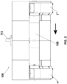
- Figure 2 shows a side view of a spray booth 100 according to the present invention, wherein two cleaning stations 1", 1′′′ are shown in their possible working position.
- the Figure shows the positions of the cleaning stations 1", 1'" when said stations are used for cleaning spraying tools: they are placed on the side opposed to the suction tower 112; said opposed side is called operator's side.
- the bold arrow shows the conveying direction of the pieces to be painted.
- the two Figures 1 and 2 show the possible positions of the cleaning stations 1.
- the cleaning stations 1 and 1' are placed on the same side of the suction tower, the footprint of the spray booth is reduced.
- placing the two cleaning stations 1", 1′′′ on the operator' side allows the human operator to more easily access a (not shown) barrel collecting the drained solvent/paint pertaining to the cleaning station.
- the possibility of placing the cleaning stations on both sides of the spray booth allows a great versatility of the spray booth, which allows to integrate it in any production line.
- said spray booths 100 are provided with at least a mobile, transparent wall 108 which allows to access the inside of the spray booth.
- Said cleaning stations 1 are placed in a position adjacent to said spray booth, with their mobile portion (see below) placed in correspondence of said mobile wall 108. This allows to provide even spray booth already installed in productive lines with at least a cleaning station according to the present invention (retrofit).
- the cleaning station 1 is tied to the spray booth 100 through suitable means (e.g. screws). Moreover, the cleaning station 1, on the perimeter that comes into contact with the spray booth 100, is provided with suitable seals, e.g. in polythene, which allow the sealing between said two components, so as to prevent the dispersion of the overspray in the environment outside the spray booth.
- the spray booth is provided with two arms, on each there being provided a spraying tool 100. Therefore, normally just two cleaning stations are provided on one of the two sides, two cleaning stations on the suction tower side, or alternatively two cleaning stations on the operator's side.
- said spray booth can be provided with four arms, on each there being provided a spraying tool; therefore four cleaning stations are needed, two on the suction tower side and two on the operator's side.
- Figures 3A, 3B show said cleaning station 1 in two axonometric views; said cleaning station 1 is shown disassembled from the spray booth 100.
- Figure 3A shows said cleaning station 1 with its external housing, with a closed cleaning drawer 5, in its rest position.
- Figure 3B shows the same cleaning station 1 deprived of its external housing, with the drawer 5 in its opened position, called cleaning position.
- said drawer 5 is in its cleaning position, the portion of the drawer 5 protruding from the cleaning station is placed inside the spray booth 100.
- Said drawer 5 is provided with a mobile protective wall 4, hinged and blocked with a magnet and a sensor, so that the spray booth 100 is stopped when the wall 4 is hit by the spraying tool.
- This is a safety mechanism: when the spraying tool 110 moves from its cleaning position toward the inside of the spray booth, generating a risk of collision, the painting is stopped.
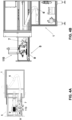
- Figures 4A, 4B show said cleaning station 1 with the opened drawer 5, during one of the cleaning steps which will be explained below.
- Figure 4A shows the cleaning station in a top view
- Figure 4B shows the same situation in a side view.
- Said cleaning station 1 comprises:
- Said devices are meant for cleaning the spraying tools 110 with which the spray booth 100 is provided.
- Figures 5A, 5B show said spraying tool 110 per se; in particular Figure 5A shows a top view while Figure 5B shows said spraying tool 110 in an axonometric view.
- Said spraying tool 110 is provided with a supporting structure on which there are provided:
- Figure 6 shows a longitudinal section of the spray booth 100; the bold arrow shows the conveying direction of pieces to be painted (not shown).
- the Figure shows an idle roller 113 and a motorized roller 114 which rotate said closed band 107 on which the pieces to be painted are conveyed.
- the Figure shows the arrangement of the two spraying tools 110, 110' in correspondence of the drawers 5, 5' of the cleaning stations 1, 1', respectively.
- the cleaning stations 1, 1' are arranged on the suction tower 112 side.
- the two shown positions are the positions taken by the two spraying tools 110, 110' during cleaning operations.
- the two spraying tools 110, 110' can take any position that is more central with respect to those shown in Figure 6 .
- the spraying tool 110 is placed in the cleaning position shown in Figure 6 , while the spraying tool 110 is free to move over the pieces to be painted, supported by the closed band 107 for painting.
- spraying tools 110, 110' are provided with four degrees of freedom in their movement:
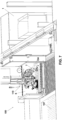
- Figure 7 shows the inside of the spray booth in a side view.
- the drawer 5 of the cleaning station is extracted from the cleaning station 1 as shown in Figure 4B , while protruding inside the spray booth 100.
- the Figure shows the draining tube 6 in a position adjacent to the spray gun 104; in particular the mouth of the tube 7 is placed so that it can collects the fluids (drained paint or solvent) which are drained from each spray gun 101-106 to be channelled into a (not shown) barrel.
- the drawer 5 In normal working, when one of the spraying tools must be cleaned e.g. 110, the drawer 5 is moved through its actuator and brought in its cleaning position wherein it protrudes in the spray booth, as shown in Figure 7 .
- the movement of the drawer can occur only if the arm 60 of the spraying tool is placed outside the opening area of the drawer 5, and moreover is in an area where interference with the arm 60' of the second spraying tool 110' is impossible.
- the arm 60 of the spraying tool to be cleaned moves in the conveying direction to approach the drawer 5; and secondly, the spraying tool 110 moves along its arm 60 to enter into the open drawer 5.
- the method according to the present invention is applied to a spray booth 100 comprising preferably two cleaning stations 1, 1' placed indifferently on the suction tower side ( Figure 1 ) or on the operator's side ( Figure 2 ). It is also possible providing just one cleaning station 1 which is manually moved toward the ingress or the egress of the pieces to be painted, according to need. As already mentioned, the cleaning of one 110 of the two spraying tools is performed by the cleaning station 1 while the spraying tool 110' is spraying the pieces to be painted, moving freely inside the spray booth 100.
- the draining spray gun 106 is optional. When provided in the spraying tool 110, the draining steps of the old painting product, of the solvent and of the new painting product are faster. As such spray gun 106 is not provided with a spraying nozzle, the diameter of the outlet hole is bigger with respect to that of the spraying guns, so as to allow a bigger flow rate than that of spray guns.
- supplying the subsequent product pushes the previous product out from the supplying circuit: e.g., supplying the solvent pushes the old painting product out of the circuit, as well as the new painting product pushes the solvent out of the circuit.
- the changes are made upstream, manually replacing the supplying reservoir from which the pump draws, or automatically by using known systems for changing colours.
- the step d) with the solvent can be omitted.
- the whole above-described method is automatic: the opening/closing of the drawer 5, the approaching of the mouth 7 of the draining tube 6 in turn to one of the spray guns 101-106, the rotation of the spraying tool 110 in order to bring each spray gun in correspondence of the mouth 7, the replacement of the painting product or solvent to supply the supplying circuit of the spraying tool 110, the actuation of the brush 9, the supply of compressed air through at least one slo6 8, are all performed by specific actuators, placed under the control of a PLC which is part of the spray booth 100.
- changing colour systems are used, i.e. systems provided with valves which allow to supply the supplying circuit of the spray booth by selecting from said plurality of reservoirs placed upstream the control valves.
- changing colour systems are well known in the art.
- the cleaning of one 110' of the two spraying tools is performed by the cleaning station 1' while the spraying tool 110 is spraying the pieces to be painted, freely moving inside the spray booth 100.
- the spraying tool 110 can start the cleaning steps according to the above-specified method, while the spraying tool 110' can start to paint the subsequent payload of pieces to be painted.
- Substantially the cleaning operation on the first of the spraying tools 110, 110' occurs at the same time of the painting operation by the second spraying tool 110', 110. Consequently, no downtime is needed to clean the spraying tools, which cleaning occurs in masked time.
Landscapes
- Chemical & Material Sciences (AREA)
- Chemical Kinetics & Catalysis (AREA)
- General Chemical & Material Sciences (AREA)
- Details Or Accessories Of Spraying Plant Or Apparatus (AREA)
- Application Of Or Painting With Fluid Materials (AREA)
- Cleaning In General (AREA)
Claims (10)
- Spritzkabine (100) zum Besprühen von zu lackierenden Teilen mit einem Lackierprodukt, umfassend:- ein System (107, 113, 114) zur Beförderung der zu lackierenden Teile innerhalb der Kabine;- einen Zufuhrkreislauf zum Zuführen eines Lackierprodukts/Lösungsmittels zu den Lackierwerkzeugen (110);- ein Plenum;- mindestens eine bewegliche Wand (108), die den Zugang zum Inneren der Spritzkabine ermöglicht;- optional ein Lesesystem für die zu lackierenden Teile;- optional ein Filtersystem;- mindestens zwei Spritzwerkzeuge (110), die zumindest eine Spritzpistole (101, 102, 103, 104, 105) umfassen, die jeweils an einem in einer Ebene und gegebenenfalls in vertikaler Richtung beweglichen, unabhängigen Arm (60, 60') angebracht sinddadurch gekennzeichnet, dass sie umfasst:
mindestens eine Reinigungsstation, vorzugsweise zwei Reinigungsstationen (1, 1'), die im Bereich der beweglichen Wand (108) angeordnet sind, wobei jede Reinigungsstation mit einer Schublade (5) versehen ist, die zwischen einer Ruheposition und einer Reinigungsposition beweglich ist, wobei die Schublade (5) umfasst:- ein Abflussrohr (6) für das Lackierprodukt/Lösungsmittel, das mit einer Öffnung (7) versehen ist;- mindestens einen Schlitz (8) für die Zufuhr von Druckluft,- mindestens eine Bürste (9) zum Bürsten der Spritzpistolen (101-105). - Spritzkabine (100) zum Besprühen von zu lackierenden Teilen mit einem Lackierprodukt, nach Anspruch 1, wobei die Spritzwerkzeuge (110, 110') ferner eine Ablasspistole (106) umfassen.
- Spritzkabine (100) zum Besprühen von zu lackierenden Teilen mit einem Lackierprodukt, nach Anspruch 1 oder 2, wobei:- die Bürste (9) zumindest teilweise in einen kleinen Behälter mit einem die Bürste benetzenden Lösungsmittel eingetaucht ist, wobei das Lösungsmittel durch denselben Zufuhrkreislauf des Lackierprodukts zugeführt wird; oder alternativ- die Bürste (9) eine Trockenbürstung der Spritzpistolen (101-105) durchführt.
- Spritzkabine (100) zum Besprühen von zu lackierenden Teilen mit einem Lackierprodukt nach einem oder mehreren der vorhergehenden Ansprüche, wobei die Reinigungsstationen (1, 1') auf derselben Seite der Spritzkabine (100) angeordnet sind, auf der auch der Absaugturm (112) angeordnet ist, oder alternativ die Reinigungsstationen (1", 1‴) auf der Bedienerseite angeordnet sind.
- Spritzkabine (100) zum Besprühen von zu lackierenden Teilen mit einem Lackierprodukt nach einem oder mehreren der vorhergehenden Ansprüche, umfassend vier Spritzwerkzeuge (110) und vier Reinigungsstationen (1 ).
- Verfahren zum Reinigen der Spritzwerkzeuge (110, 110') einer Spritzkabine (100) nach einem der Ansprüche 1-5, dadurch gekennzeichnet, dass es die folgenden Schritte umfasst:a. Einbringen der Schublade (5) der Reinigungsstation (1) in das Innere der Spritzkabine (100);b. Einbringen des mit Spritzpistolen (101-105) versehenen Spritzwerkzeugs (100) in die Schublade (5);c. Entleeren des Zufuhrkreislaufs der Spritzpistole, der ein erstes Lackierprodukt leitet, indem jede Spritzpistole vor der Mündung (7) des Ablassrohrs (6) positioniert wird;d. optionales Zuführen eines Lösungsmittels zu den Spritzpistolen (101-105 und optional 106), indem jede Spritzpistole vor der Mündung (7) des Ablassrohrs (6) positioniert wird;e. externes Bürsten der Spritzpistolen (101-105) in Form von Trockenbürsten oder Nassbürsten mittels der Bürste (9);f. externes Ausblasen des Spritzwerkzeugs (110) durch Druckluft, die durch mindestens den Schlitz (8) zugeführt wird;g. Zuführen eines neuen Lackierproduktes bis zu den Spritzpistolen (101-105 und optional 106); das Spritzwerkzeug (110) ist für die Wiederaufnahme des Lackierens bereit;h. Austreten des Spritzwerkzeugs (110) aus der Reinigungsschublade (5);i. Schließen der Reinigungsstation (1), wobei die Schublade (5) in das Innere der Reinigungsstation (1) zurückkehrt.
- Verfahren zum Reinigen der Spritzwerkzeuge (110, 110') einer Spritzkabine (100) nach Anspruch 6, bei dem die Verfahrensschritte automatisch erfolgen, wobei jede Komponente mit einem geeigneten Aktuator versehen ist, der von einer in der Spritzkabine (100) vorhandenen SPS gesteuert wird.
- Verfahren zum Reinigen der Spritzwerkzeuge (110, 110') einer Spritzkabine (100) nach Anspruch 6 oder 7, wobei, wenn das Spritzwerkzeug (110, 110') mit der Ablasspistole (106) versehen ist, die Lackierprodukte und das Lösungsmittel (106) zunächst durch die Ablasspistole (6) abgelassen werden.
- Verfahren zum Reinigen der Spritzwerkzeuge (110, 110') einer Spritzkabine (100) nach einem oder mehreren der Ansprüche 6-8, bei dem, wenn die Bürste (9) zumindest teilweise in einen kleinen, Lösungsmittel enthaltenden Tank eingetaucht ist, die Zufuhr von Lösungsmittel durch denselben Zufuhrkreislauf erfolgt, der das Innere der Spritzpistolen (101-105) versorgt, vorzugsweise mit einem Druck, der niedriger ist als der normale Druck, der zum Spritzen verwendet wird.
- Verfahren zum Reinigen der Spritzwerkzeuge (110, 110') einer Spritzkabine (100) nach einem oder mehreren der Ansprüche 6-9, wobei das Besprühen der zu lackierenden Teile intermittierend oder kontinuierlich erfolgt.
Applications Claiming Priority (1)
| Application Number | Priority Date | Filing Date | Title |
|---|---|---|---|
| IT102021000007592A IT202100007592A1 (it) | 2021-03-29 | 2021-03-29 | Stazione di pulizia delle pistole di spruzzatura in una cabina di verniciatura, e metodo di utilizzo |
Publications (2)
| Publication Number | Publication Date |
|---|---|
| EP4066947A1 EP4066947A1 (de) | 2022-10-05 |
| EP4066947B1 true EP4066947B1 (de) | 2024-08-14 |
Family
ID=76159793
Family Applications (1)
| Application Number | Title | Priority Date | Filing Date |
|---|---|---|---|
| EP22164638.3A Active EP4066947B1 (de) | 2021-03-29 | 2022-03-28 | Reinigungsstation zum reinigen der spritzpistolen in einer spritzkabine und verfahren |
Country Status (5)
| Country | Link |
|---|---|
| US (1) | US11845098B2 (de) |
| EP (1) | EP4066947B1 (de) |
| CN (1) | CN115138518A (de) |
| BR (1) | BR102022005871A2 (de) |
| IT (1) | IT202100007592A1 (de) |
Families Citing this family (4)
| Publication number | Priority date | Publication date | Assignee | Title |
|---|---|---|---|---|
| CN115970925B (zh) * | 2022-10-25 | 2025-08-29 | 舟山中远海运重工有限公司 | 一种船舶用自动喷漆装置 |
| CN115780150B (zh) * | 2022-11-28 | 2025-08-05 | 日善电脑配件(嘉善)有限公司 | 一种3c电子产品加工用表面喷涂装置 |
| US12304055B2 (en) * | 2023-02-15 | 2025-05-20 | Nathan John Tobkin | Remote spray foam system for polyurethane insulation foam |
| US12383920B2 (en) | 2023-02-15 | 2025-08-12 | Nathan John Tobkin | Remote spray foam method |
Family Cites Families (14)
| Publication number | Priority date | Publication date | Assignee | Title |
|---|---|---|---|---|
| CA1293909C (en) | 1987-07-16 | 1992-01-07 | Soichiro Yamamoto | Apparatus for automatic cleaning of paint spray gun assemblies and their component parts |
| NZ234541A (en) * | 1989-07-19 | 1992-08-26 | Balisbex Pty Ltd | Parts cleaning apparatus; removable sludge chamber while solvent remains in apparatus |
| US20030127046A1 (en) * | 2002-01-09 | 2003-07-10 | Harley-Davidson Motor Company Group, Inc. | Paint spray gun cleaner |
| CN102762310B (zh) * | 2010-02-12 | 2015-06-03 | 本田技研工业株式会社 | 喷涂枪的清洗装置及清洗方法 |
| DE202012104930U1 (de) | 2012-12-18 | 2013-01-11 | Metso Paper, Inc. | Vorrichtung zur Reinigung von Sprühdüsen einer Faserbahnbeschichtungsvorrichtung |
| CN105377445B (zh) | 2013-07-19 | 2018-03-27 | 固瑞克明尼苏达有限公司 | 多点密封件润滑系统 |
| FR3052988A1 (fr) * | 2016-06-28 | 2017-12-29 | Exel Ind | Procede de nettoyage automatique, poste de sechage et systeme de nettoyage comprenant un tel poste de sechage |
| CN106513217A (zh) | 2016-11-07 | 2017-03-22 | 上海客辉自动化设备有限公司 | 一种具有自动清洗功能的四轴喷涂机 |
| CN106362898B (zh) | 2016-11-14 | 2019-01-04 | 青岛金光鸿智能机械电子有限公司 | 自动喷涂喷头清洗及废料收集装置 |
| CN107321538A (zh) | 2017-08-16 | 2017-11-07 | 深圳市泰达机器人有限公司 | 一种喷漆设备喷嘴自动清洗装置 |
| GB2566452A (en) | 2017-09-12 | 2019-03-20 | Carlisle Fluid Tech Inc | Colour change system for powder coating |
| CN110605208A (zh) | 2019-09-24 | 2019-12-24 | 江苏纵湖涂装设备产业研究院有限公司 | 一种喷头自动清理的智能涂装加工设备 |
| CN111632785A (zh) | 2020-06-02 | 2020-09-08 | 合肥昊明智能科技有限公司 | 一种工业机械自动化清洗装置 |
| CN111822210A (zh) | 2020-08-05 | 2020-10-27 | 福州织步曲科技有限公司 | 一种可自动清洗喷漆管的喷漆装置 |
-
2021
- 2021-03-29 IT IT102021000007592A patent/IT202100007592A1/it unknown
-
2022
- 2022-03-22 US US17/701,532 patent/US11845098B2/en active Active
- 2022-03-28 EP EP22164638.3A patent/EP4066947B1/de active Active
- 2022-03-28 BR BR102022005871-7A patent/BR102022005871A2/pt unknown
- 2022-03-28 CN CN202210312516.4A patent/CN115138518A/zh active Pending
Also Published As
| Publication number | Publication date |
|---|---|
| US11845098B2 (en) | 2023-12-19 |
| IT202100007592A1 (it) | 2022-09-29 |
| US20220305514A1 (en) | 2022-09-29 |
| BR102022005871A2 (pt) | 2022-10-04 |
| CN115138518A (zh) | 2022-10-04 |
| EP4066947A1 (de) | 2022-10-05 |
Similar Documents
| Publication | Publication Date | Title |
|---|---|---|
| EP4066947A1 (de) | Reinigungsstation zum reinigen der spritzpistolen in einer spritzkabine und verfahren | |
| US4830882A (en) | Method of and apparatus for cleaning paint spray guns | |
| US20070169691A1 (en) | Automatic retouching device for a powder-coating booth | |
| CN107097205B (zh) | 涂装装置和对应的运行方法 | |
| EP3603818B1 (de) | Einrichtung zum lackieren von artikeln | |
| US20140245953A1 (en) | System for coating, in particular for painting, articles, in particular vehicle bodies | |
| ITVI20080282A1 (it) | Apparecchiatura perfezionata per la lavorazione di superfici laminari flessibili, quali, in particolare, pelli di conceria e relativo metodo di lavorazione. | |
| US6896010B2 (en) | Method and device for filling a paint reservoir in an automated painting installation | |
| HK40079426A (en) | Cleaning station and method for cleaning spray gun in spray booth | |
| EP2953726B1 (de) | System und verfahren zur äusseren behandlung von gegerbtem leder | |
| WO2017033074A1 (en) | Coating booth | |
| EP4461420B1 (de) | Spritzlackiergerät, sogenannte lackierkabine, die mit einer schnellentleerstation und einem produktwechsel ausgestattet ist, und entsprechendes verfahren | |
| CN105170379A (zh) | 内喷机 | |
| CN211385478U (zh) | 一种保温装饰板生产用自动喷漆机 | |
| CN215586927U (zh) | 用于对待涂装的物体进行涂装的喷涂柜 | |
| CN107597486A (zh) | 一种喷雾喷涂方法 | |
| JP5389532B2 (ja) | 塗装システム | |
| EP3681643B1 (de) | Farbwechselsystem für pulverbeschichtung | |
| US3386415A (en) | Coating machine | |
| CN107812645A (zh) | 新型喷涂装置 | |
| CN107716157A (zh) | 新型喷雾喷涂方法 | |
| CN109928642A (zh) | 一种酒瓶喷涂装置 | |
| CN107952610A (zh) | 一种喷雾喷涂装置 | |
| CN107626483A (zh) | 新型喷雾喷涂装置 | |
| CN107876277A (zh) | 新型喷涂方法 |
Legal Events
| Date | Code | Title | Description |
|---|---|---|---|
| PUAI | Public reference made under article 153(3) epc to a published international application that has entered the european phase |
Free format text: ORIGINAL CODE: 0009012 |
|
| STAA | Information on the status of an ep patent application or granted ep patent |
Free format text: STATUS: THE APPLICATION HAS BEEN PUBLISHED |
|
| AK | Designated contracting states |
Kind code of ref document: A1 Designated state(s): AL AT BE BG CH CY CZ DE DK EE ES FI FR GB GR HR HU IE IS IT LI LT LU LV MC MK MT NL NO PL PT RO RS SE SI SK SM TR |
|
| STAA | Information on the status of an ep patent application or granted ep patent |
Free format text: STATUS: REQUEST FOR EXAMINATION WAS MADE |
|
| 17P | Request for examination filed |
Effective date: 20221109 |
|
| RBV | Designated contracting states (corrected) |
Designated state(s): AL AT BE BG CH CY CZ DE DK EE ES FI FR GB GR HR HU IE IS IT LI LT LU LV MC MK MT NL NO PL PT RO RS SE SI SK SM TR |
|
| RIN1 | Information on inventor provided before grant (corrected) |
Inventor name: LOMBINI, MARCO Inventor name: CHIARINI, STEFANO Inventor name: PUNGETTI, CRISTIAN |
|
| RIC1 | Information provided on ipc code assigned before grant |
Ipc: B05B 16/00 20180101ALI20230301BHEP Ipc: B05B 15/00 20060101AFI20230301BHEP |
|
| STAA | Information on the status of an ep patent application or granted ep patent |
Free format text: STATUS: EXAMINATION IS IN PROGRESS |
|
| 17Q | First examination report despatched |
Effective date: 20230421 |
|
| GRAP | Despatch of communication of intention to grant a patent |
Free format text: ORIGINAL CODE: EPIDOSNIGR1 |
|
| STAA | Information on the status of an ep patent application or granted ep patent |
Free format text: STATUS: GRANT OF PATENT IS INTENDED |
|
| INTG | Intention to grant announced |
Effective date: 20240320 |
|
| GRAS | Grant fee paid |
Free format text: ORIGINAL CODE: EPIDOSNIGR3 |
|
| GRAA | (expected) grant |
Free format text: ORIGINAL CODE: 0009210 |
|
| STAA | Information on the status of an ep patent application or granted ep patent |
Free format text: STATUS: THE PATENT HAS BEEN GRANTED |
|
| AK | Designated contracting states |
Kind code of ref document: B1 Designated state(s): AL AT BE BG CH CY CZ DE DK EE ES FI FR GB GR HR HU IE IS IT LI LT LU LV MC MK MT NL NO PL PT RO RS SE SI SK SM TR |
|
| REG | Reference to a national code |
Ref country code: GB Ref legal event code: FG4D |
|
| REG | Reference to a national code |
Ref country code: CH Ref legal event code: EP |
|
| REG | Reference to a national code |
Ref country code: DE Ref legal event code: R096 Ref document number: 602022005255 Country of ref document: DE |
|
| REG | Reference to a national code |
Ref country code: IE Ref legal event code: FG4D |
|
| REG | Reference to a national code |
Ref country code: LT Ref legal event code: MG9D |
|
| REG | Reference to a national code |
Ref country code: NL Ref legal event code: MP Effective date: 20240814 |
|
| PG25 | Lapsed in a contracting state [announced via postgrant information from national office to epo] |
Ref country code: NO Free format text: LAPSE BECAUSE OF FAILURE TO SUBMIT A TRANSLATION OF THE DESCRIPTION OR TO PAY THE FEE WITHIN THE PRESCRIBED TIME-LIMIT Effective date: 20241114 |
|
| REG | Reference to a national code |
Ref country code: AT Ref legal event code: MK05 Ref document number: 1712803 Country of ref document: AT Kind code of ref document: T Effective date: 20240814 |
|
| PG25 | Lapsed in a contracting state [announced via postgrant information from national office to epo] |
Ref country code: NL Free format text: LAPSE BECAUSE OF FAILURE TO SUBMIT A TRANSLATION OF THE DESCRIPTION OR TO PAY THE FEE WITHIN THE PRESCRIBED TIME-LIMIT Effective date: 20240814 Ref country code: GR Free format text: LAPSE BECAUSE OF FAILURE TO SUBMIT A TRANSLATION OF THE DESCRIPTION OR TO PAY THE FEE WITHIN THE PRESCRIBED TIME-LIMIT Effective date: 20241115 Ref country code: FI Free format text: LAPSE BECAUSE OF FAILURE TO SUBMIT A TRANSLATION OF THE DESCRIPTION OR TO PAY THE FEE WITHIN THE PRESCRIBED TIME-LIMIT Effective date: 20240814 Ref country code: PL Free format text: LAPSE BECAUSE OF FAILURE TO SUBMIT A TRANSLATION OF THE DESCRIPTION OR TO PAY THE FEE WITHIN THE PRESCRIBED TIME-LIMIT Effective date: 20240814 Ref country code: PT Free format text: LAPSE BECAUSE OF FAILURE TO SUBMIT A TRANSLATION OF THE DESCRIPTION OR TO PAY THE FEE WITHIN THE PRESCRIBED TIME-LIMIT Effective date: 20241216 |
|
| PG25 | Lapsed in a contracting state [announced via postgrant information from national office to epo] |
Ref country code: BG Free format text: LAPSE BECAUSE OF FAILURE TO SUBMIT A TRANSLATION OF THE DESCRIPTION OR TO PAY THE FEE WITHIN THE PRESCRIBED TIME-LIMIT Effective date: 20240814 |
|
| PG25 | Lapsed in a contracting state [announced via postgrant information from national office to epo] |
Ref country code: LV Free format text: LAPSE BECAUSE OF FAILURE TO SUBMIT A TRANSLATION OF THE DESCRIPTION OR TO PAY THE FEE WITHIN THE PRESCRIBED TIME-LIMIT Effective date: 20240814 |
|
| PG25 | Lapsed in a contracting state [announced via postgrant information from national office to epo] |
Ref country code: AT Free format text: LAPSE BECAUSE OF FAILURE TO SUBMIT A TRANSLATION OF THE DESCRIPTION OR TO PAY THE FEE WITHIN THE PRESCRIBED TIME-LIMIT Effective date: 20240814 Ref country code: IS Free format text: LAPSE BECAUSE OF FAILURE TO SUBMIT A TRANSLATION OF THE DESCRIPTION OR TO PAY THE FEE WITHIN THE PRESCRIBED TIME-LIMIT Effective date: 20241214 |
|
| PG25 | Lapsed in a contracting state [announced via postgrant information from national office to epo] |
Ref country code: HR Free format text: LAPSE BECAUSE OF FAILURE TO SUBMIT A TRANSLATION OF THE DESCRIPTION OR TO PAY THE FEE WITHIN THE PRESCRIBED TIME-LIMIT Effective date: 20240814 |
|
| PG25 | Lapsed in a contracting state [announced via postgrant information from national office to epo] |
Ref country code: RS Free format text: LAPSE BECAUSE OF FAILURE TO SUBMIT A TRANSLATION OF THE DESCRIPTION OR TO PAY THE FEE WITHIN THE PRESCRIBED TIME-LIMIT Effective date: 20241114 Ref country code: ES Free format text: LAPSE BECAUSE OF FAILURE TO SUBMIT A TRANSLATION OF THE DESCRIPTION OR TO PAY THE FEE WITHIN THE PRESCRIBED TIME-LIMIT Effective date: 20240814 |
|
| PG25 | Lapsed in a contracting state [announced via postgrant information from national office to epo] |
Ref country code: RS Free format text: LAPSE BECAUSE OF FAILURE TO SUBMIT A TRANSLATION OF THE DESCRIPTION OR TO PAY THE FEE WITHIN THE PRESCRIBED TIME-LIMIT Effective date: 20241114 Ref country code: PT Free format text: LAPSE BECAUSE OF FAILURE TO SUBMIT A TRANSLATION OF THE DESCRIPTION OR TO PAY THE FEE WITHIN THE PRESCRIBED TIME-LIMIT Effective date: 20241216 Ref country code: PL Free format text: LAPSE BECAUSE OF FAILURE TO SUBMIT A TRANSLATION OF THE DESCRIPTION OR TO PAY THE FEE WITHIN THE PRESCRIBED TIME-LIMIT Effective date: 20240814 Ref country code: NO Free format text: LAPSE BECAUSE OF FAILURE TO SUBMIT A TRANSLATION OF THE DESCRIPTION OR TO PAY THE FEE WITHIN THE PRESCRIBED TIME-LIMIT Effective date: 20241114 Ref country code: NL Free format text: LAPSE BECAUSE OF FAILURE TO SUBMIT A TRANSLATION OF THE DESCRIPTION OR TO PAY THE FEE WITHIN THE PRESCRIBED TIME-LIMIT Effective date: 20240814 Ref country code: LV Free format text: LAPSE BECAUSE OF FAILURE TO SUBMIT A TRANSLATION OF THE DESCRIPTION OR TO PAY THE FEE WITHIN THE PRESCRIBED TIME-LIMIT Effective date: 20240814 Ref country code: IS Free format text: LAPSE BECAUSE OF FAILURE TO SUBMIT A TRANSLATION OF THE DESCRIPTION OR TO PAY THE FEE WITHIN THE PRESCRIBED TIME-LIMIT Effective date: 20241214 Ref country code: HR Free format text: LAPSE BECAUSE OF FAILURE TO SUBMIT A TRANSLATION OF THE DESCRIPTION OR TO PAY THE FEE WITHIN THE PRESCRIBED TIME-LIMIT Effective date: 20240814 Ref country code: GR Free format text: LAPSE BECAUSE OF FAILURE TO SUBMIT A TRANSLATION OF THE DESCRIPTION OR TO PAY THE FEE WITHIN THE PRESCRIBED TIME-LIMIT Effective date: 20241115 Ref country code: FI Free format text: LAPSE BECAUSE OF FAILURE TO SUBMIT A TRANSLATION OF THE DESCRIPTION OR TO PAY THE FEE WITHIN THE PRESCRIBED TIME-LIMIT Effective date: 20240814 Ref country code: ES Free format text: LAPSE BECAUSE OF FAILURE TO SUBMIT A TRANSLATION OF THE DESCRIPTION OR TO PAY THE FEE WITHIN THE PRESCRIBED TIME-LIMIT Effective date: 20240814 Ref country code: BG Free format text: LAPSE BECAUSE OF FAILURE TO SUBMIT A TRANSLATION OF THE DESCRIPTION OR TO PAY THE FEE WITHIN THE PRESCRIBED TIME-LIMIT Effective date: 20240814 Ref country code: AT Free format text: LAPSE BECAUSE OF FAILURE TO SUBMIT A TRANSLATION OF THE DESCRIPTION OR TO PAY THE FEE WITHIN THE PRESCRIBED TIME-LIMIT Effective date: 20240814 |
|
| PG25 | Lapsed in a contracting state [announced via postgrant information from national office to epo] |
Ref country code: RO Free format text: LAPSE BECAUSE OF FAILURE TO SUBMIT A TRANSLATION OF THE DESCRIPTION OR TO PAY THE FEE WITHIN THE PRESCRIBED TIME-LIMIT Effective date: 20240814 Ref country code: DK Free format text: LAPSE BECAUSE OF FAILURE TO SUBMIT A TRANSLATION OF THE DESCRIPTION OR TO PAY THE FEE WITHIN THE PRESCRIBED TIME-LIMIT Effective date: 20240814 Ref country code: SM Free format text: LAPSE BECAUSE OF FAILURE TO SUBMIT A TRANSLATION OF THE DESCRIPTION OR TO PAY THE FEE WITHIN THE PRESCRIBED TIME-LIMIT Effective date: 20240814 |
|
| PG25 | Lapsed in a contracting state [announced via postgrant information from national office to epo] |
Ref country code: EE Free format text: LAPSE BECAUSE OF FAILURE TO SUBMIT A TRANSLATION OF THE DESCRIPTION OR TO PAY THE FEE WITHIN THE PRESCRIBED TIME-LIMIT Effective date: 20240814 |
|
| PG25 | Lapsed in a contracting state [announced via postgrant information from national office to epo] |
Ref country code: CZ Free format text: LAPSE BECAUSE OF FAILURE TO SUBMIT A TRANSLATION OF THE DESCRIPTION OR TO PAY THE FEE WITHIN THE PRESCRIBED TIME-LIMIT Effective date: 20240814 |
|
| PG25 | Lapsed in a contracting state [announced via postgrant information from national office to epo] |
Ref country code: SK Free format text: LAPSE BECAUSE OF FAILURE TO SUBMIT A TRANSLATION OF THE DESCRIPTION OR TO PAY THE FEE WITHIN THE PRESCRIBED TIME-LIMIT Effective date: 20240814 |
|
| REG | Reference to a national code |
Ref country code: DE Ref legal event code: R097 Ref document number: 602022005255 Country of ref document: DE |
|
| PLBE | No opposition filed within time limit |
Free format text: ORIGINAL CODE: 0009261 |
|
| STAA | Information on the status of an ep patent application or granted ep patent |
Free format text: STATUS: NO OPPOSITION FILED WITHIN TIME LIMIT |
|
| 26N | No opposition filed |
Effective date: 20250515 |
|
| PG25 | Lapsed in a contracting state [announced via postgrant information from national office to epo] |
Ref country code: SE Free format text: LAPSE BECAUSE OF FAILURE TO SUBMIT A TRANSLATION OF THE DESCRIPTION OR TO PAY THE FEE WITHIN THE PRESCRIBED TIME-LIMIT Effective date: 20240814 |
|
| PG25 | Lapsed in a contracting state [announced via postgrant information from national office to epo] |
Ref country code: MC Free format text: LAPSE BECAUSE OF FAILURE TO SUBMIT A TRANSLATION OF THE DESCRIPTION OR TO PAY THE FEE WITHIN THE PRESCRIBED TIME-LIMIT Effective date: 20240814 |
|
| REG | Reference to a national code |
Ref country code: CH Ref legal event code: H13 Free format text: ST27 STATUS EVENT CODE: U-0-0-H10-H13 (AS PROVIDED BY THE NATIONAL OFFICE) Effective date: 20251023 |
|
| PG25 | Lapsed in a contracting state [announced via postgrant information from national office to epo] |
Ref country code: LU Free format text: LAPSE BECAUSE OF NON-PAYMENT OF DUE FEES Effective date: 20250328 |
|
| REG | Reference to a national code |
Ref country code: BE Ref legal event code: MM Effective date: 20250331 |
|
| PG25 | Lapsed in a contracting state [announced via postgrant information from national office to epo] |
Ref country code: FR Free format text: LAPSE BECAUSE OF NON-PAYMENT OF DUE FEES Effective date: 20250331 |
|
| PG25 | Lapsed in a contracting state [announced via postgrant information from national office to epo] |
Ref country code: BE Free format text: LAPSE BECAUSE OF NON-PAYMENT OF DUE FEES Effective date: 20250331 |
|
| PG25 | Lapsed in a contracting state [announced via postgrant information from national office to epo] |
Ref country code: CH Free format text: LAPSE BECAUSE OF NON-PAYMENT OF DUE FEES Effective date: 20250331 |
|
| PG25 | Lapsed in a contracting state [announced via postgrant information from national office to epo] |
Ref country code: IE Free format text: LAPSE BECAUSE OF NON-PAYMENT OF DUE FEES Effective date: 20250328 |
|
| PGFP | Annual fee paid to national office [announced via postgrant information from national office to epo] |
Ref country code: DE Payment date: 20260219 Year of fee payment: 5 |
|
| PGFP | Annual fee paid to national office [announced via postgrant information from national office to epo] |
Ref country code: IT Payment date: 20260219 Year of fee payment: 5 |
|
| PGFP | Annual fee paid to national office [announced via postgrant information from national office to epo] |
Ref country code: TR Payment date: 20260227 Year of fee payment: 5 |