EP4066178B1 - Verfahren und systeme zur komponentenbasierten modellierung reduzierter ordnung für strukturelle digitale zwillinge im industriellen massstab - Google Patents
Verfahren und systeme zur komponentenbasierten modellierung reduzierter ordnung für strukturelle digitale zwillinge im industriellen massstab Download PDFInfo
- Publication number
- EP4066178B1 EP4066178B1 EP20807508.5A EP20807508A EP4066178B1 EP 4066178 B1 EP4066178 B1 EP 4066178B1 EP 20807508 A EP20807508 A EP 20807508A EP 4066178 B1 EP4066178 B1 EP 4066178B1
- Authority
- EP
- European Patent Office
- Prior art keywords
- computing device
- physical asset
- model
- operational data
- physical
- Prior art date
- Legal status (The legal status is an assumption and is not a legal conclusion. Google has not performed a legal analysis and makes no representation as to the accuracy of the status listed.)
- Active
Links
Images


Classifications
-
- G—PHYSICS
- G06—COMPUTING OR CALCULATING; COUNTING
- G06Q—INFORMATION AND COMMUNICATION TECHNOLOGY [ICT] SPECIALLY ADAPTED FOR ADMINISTRATIVE, COMMERCIAL, FINANCIAL, MANAGERIAL OR SUPERVISORY PURPOSES; SYSTEMS OR METHODS SPECIALLY ADAPTED FOR ADMINISTRATIVE, COMMERCIAL, FINANCIAL, MANAGERIAL OR SUPERVISORY PURPOSES, NOT OTHERWISE PROVIDED FOR
- G06Q10/00—Administration; Management
- G06Q10/06—Resources, workflows, human or project management; Enterprise or organisation planning; Enterprise or organisation modelling
- G06Q10/063—Operations research, analysis or management
-
- B—PERFORMING OPERATIONS; TRANSPORTING
- B63—SHIPS OR OTHER WATERBORNE VESSELS; RELATED EQUIPMENT
- B63B—SHIPS OR OTHER WATERBORNE VESSELS; EQUIPMENT FOR SHIPPING
- B63B3/00—Hulls characterised by their structure or component parts
- B63B3/14—Hull parts
-
- B—PERFORMING OPERATIONS; TRANSPORTING
- B63—SHIPS OR OTHER WATERBORNE VESSELS; RELATED EQUIPMENT
- B63B—SHIPS OR OTHER WATERBORNE VESSELS; EQUIPMENT FOR SHIPPING
- B63B71/00—Designing vessels; Predicting their performance
- B63B71/10—Designing vessels; Predicting their performance using computer simulation, e.g. finite element method [FEM] or computational fluid dynamics [CFD]
-
- G—PHYSICS
- G06—COMPUTING OR CALCULATING; COUNTING
- G06F—ELECTRIC DIGITAL DATA PROCESSING
- G06F30/00—Computer-aided design [CAD]
- G06F30/10—Geometric CAD
- G06F30/15—Vehicle, aircraft or watercraft design
-
- G—PHYSICS
- G06—COMPUTING OR CALCULATING; COUNTING
- G06F—ELECTRIC DIGITAL DATA PROCESSING
- G06F30/00—Computer-aided design [CAD]
- G06F30/20—Design optimisation, verification or simulation
-
- G—PHYSICS
- G06—COMPUTING OR CALCULATING; COUNTING
- G06F—ELECTRIC DIGITAL DATA PROCESSING
- G06F30/00—Computer-aided design [CAD]
- G06F30/20—Design optimisation, verification or simulation
- G06F30/23—Design optimisation, verification or simulation using finite element methods [FEM] or finite difference methods [FDM]
-
- G—PHYSICS
- G06—COMPUTING OR CALCULATING; COUNTING
- G06Q—INFORMATION AND COMMUNICATION TECHNOLOGY [ICT] SPECIALLY ADAPTED FOR ADMINISTRATIVE, COMMERCIAL, FINANCIAL, MANAGERIAL OR SUPERVISORY PURPOSES; SYSTEMS OR METHODS SPECIALLY ADAPTED FOR ADMINISTRATIVE, COMMERCIAL, FINANCIAL, MANAGERIAL OR SUPERVISORY PURPOSES, NOT OTHERWISE PROVIDED FOR
- G06Q10/00—Administration; Management
- G06Q10/04—Forecasting or optimisation specially adapted for administrative or management purposes, e.g. linear programming or "cutting stock problem"
-
- G—PHYSICS
- G06—COMPUTING OR CALCULATING; COUNTING
- G06Q—INFORMATION AND COMMUNICATION TECHNOLOGY [ICT] SPECIALLY ADAPTED FOR ADMINISTRATIVE, COMMERCIAL, FINANCIAL, MANAGERIAL OR SUPERVISORY PURPOSES; SYSTEMS OR METHODS SPECIALLY ADAPTED FOR ADMINISTRATIVE, COMMERCIAL, FINANCIAL, MANAGERIAL OR SUPERVISORY PURPOSES, NOT OTHERWISE PROVIDED FOR
- G06Q10/00—Administration; Management
- G06Q10/08—Logistics, e.g. warehousing, loading or distribution; Inventory or stock management
- G06Q10/087—Inventory or stock management, e.g. order filling, procurement or balancing against orders
-
- G—PHYSICS
- G06—COMPUTING OR CALCULATING; COUNTING
- G06T—IMAGE DATA PROCESSING OR GENERATION, IN GENERAL
- G06T15/00—3D [Three Dimensional] image rendering
- G06T15/005—General purpose rendering architectures
Definitions
- a method for maintaining a physical asset based on recommendations generated by analyzing a model of the physical asset, the model comprising a plurality of components and forming a physics-based digital twin of the physical asset includes constructing, by a computing device, using a port-reduced static condensation reduced basis element approximation of at least a portion of a partial differential equation, a composite model of a plurality of models, each of the plurality of models representing at least one of a plurality of components, each of the plurality of components representing at least one region of a physical asset.
- the method includes analyzing, by the computing device, for at least one model in the plurality of models, an error indicator identifying a level of error associated with the at least one model, to determine that the identified level of error exceeds a tolerance level.
- the method includes increasing, by the computing device, a number of basis functions in the port-reduced static condensation reduced basis element approximation, based upon a determination that the at least one model has a level of error exceeding the tolerance level.
- the method includes repeating the error analysis and increasing of basis functions for each model in the plurality of models until the level of error for each of the plurality of models is beneath the tolerance level.
- the method includes receiving, by the computing device, from a first operational data source associated with the physical asset, first operational data associated with at least one region of the physical asset represented by at least one parameter of at least one component in die plurality of components.
- the method includes updating, by the computing device, the composite model, based upon the received first operational data.
- the method includes providing, by the computing device, a recommendation for maintaining the physical asset, based upon the updated composite model.
- the methods and systems described herein provide functionality for maintaining a physical asset based on recommendations generated by analyzing a model of the physical asset, the model comprising a plurality of components and forming a physics-based digital twin of the physical asset.
- the methods and systems described herein may provide functionality for identifying one or more aspects of the physical asset that should be inspected (e.g., subject to a physical inspection).
- the methods and systems described herein may provide functionality for determining a level of feasibility of a proposed modification to the physical asset.
- the methods and systems described herein may provide functionality for determining a level of operability of the physical asset.
- the methods and systems described herein may provide functionality for performing structural integrity monitoring and reassessment during operation, which may enable identification of extra capacity present in the asset (and hence may avoid early decommissioning) or overly onerous maintenance regimes, while also tracking the impact of extreme or unpredictable events to ensure safety and reliability.
- this goal of asset tracking and integrity monitoring during operations motivates the concept of a structural digital twin.
- the term digital twin may refer to a computational replica of a physical asset which is kept in sync with the asset during its operational lifetime, based on inspection and sensor data, for example.
- a structural digital twin may refer to the specific case in which the purpose of the digital twin is to assess structural integrity based on the "as is" state of the asset.
- Updates to a structural digital twin may capture any structurally relevant changes to the asset, and can be based on, for example, inspection data (e.g. visual inspection, ultrasound thickness measurements, laser scans) or sensor measurements (e.g. accelerometers, strain gauges, environmental monitoring).
- inspection data e.g. visual inspection, ultrasound thickness measurements, laser scans
- sensor measurements e.g. accelerometers, strain gauges, environmental monitoring.
- This inspection and instrumentation significantly reduces, if not eliminates, the uncertainty associated with operating conditions since it allows for continuous updates the digital twin to reflect the true state of the asset and its environment.
- users of the methods and systems described herein may therefore develop updated asset management plans informed by the structural digital twin (e.g. for inspection, maintenance, repair, changes to allowable operating conditions, damage or accident response, or asset life extension) instead of relying on the plans that were developed at design-time.
- structural digital twins may be provided for physical assets within industrial systems, such as fixed or floating offshore structures, aircraft, mining machinery, rotating machinery, or pressure vessels.
- the methods and systems described herein therefore, include a component-based reduced order modeling framework based on the Static Condensation Reduced Basis Element (SCREE) method that enables fast, holistic, detailed, and parametric structural analysis of large-scale industrial systems.
- SCREE Static Condensation Reduced Basis Element
- the methods and systems described herein provide functionality for generating and updating structural digital twins that satisfy four properties: holistic and detailed modeling, speed, parametric modeling, and standards compliance and certifiable accuracy.
- Structural digital twins should enable "screening" of an entire system to identify the most likely "failure locations," e.g. at stress and fatigue hotspots, so that these locations can be prioritized in inspection planning, for example.
- a holistic and detailed model is used, in order to accurately resolve the stress throughout the components of the physical asset.
- a structural digital twin should represent an entire asset as one holistic model, and should provide a sufficient level of detail such that all relevant data can be mapped in an accurate manner into the digital twin. Through this approach the digital twin may capture the local, non-local, and cumulative effects of all updates (e.g. modifications, defects, damage) that have been measured or observed.
- a status report from a structural digital twin typically involves solving thousands of different load cases, e.g., to perform a fatigue life estimation of critical parts, or to perform a strength check based on the relevant industry standards under a wide range of "what if" scenarios.
- the full battery of analysis results need to be completed quickly enough so that the status report is available in time for the decision-making process. Therefore, the methods and systems described herein provide functionality for generating and updating structural digital twins within a timeframe required for the generated or updated structural digital twin to inform decision making.
- An aspect of a structural digital twin is that it may evolve (and in some embodiments continuously evolves), either based on the updated state of the asset, or due to modifications imposed by the operator who may want to assess different proposed changes or "what if' scenarios. Therefore, the methods and systems described herein provide functionality for generating and updating structural digital twins that are readily and efficiently modifiable.
- a parametric modeling approach may facilitate such modifications, since parametric modeling enables properties to be modified via changing "dials," e.g. to vary stiffnesses, densities, loads, geometry, etc., and to be resolved automatically and efficiently.
- Parametric modeling also facilities uncertainty quantification since model parameters can be statistically sampled in order to assess uncertainty in the digital twin's predictions, such as assessment structural fatigue under a range of loading scenarios or corrosion rates. This type of statistical uncertainty analysis allows for risk-based planning of asset management based on a digital twin.
- Structural digital twins are typically deployed for safety critical and high-value assets, and there are many existing codes from regulators and standards bodies that govern the type of analysis that should be used in this context. Therefore, the methods and systems described herein provide functionality for generating and updating structural digital twins that comply with these standards in order for regulators and operators to have full confidence in the results it provides while providing analysis results that may be checked to confirm their accuracy and reliability.
- FE Finite Element
- FE certainly satisfies requirements around standards compliance and certifiable accuracy, but it has significant limitations for the other three items.
- holistic and detailed modeling and speed the computational speed and memory requirements of FE typically grow supertinearin, with the number of degrees of freedom, and hence in most practical circumstances detailed and holistic modeling is not feasible for large-scale systems with FE.
- This issue with FE has led to the development of many submodeling-based workflows (coarse global models and separate fine local models), but the submodeling approach ignores the non-local and cumulative effects we aim to capture when performing an update to a structural digital twin.
- parametric modeling FE is not inherently parametric, in the sense that any parametric change requires a new (often computationally intensive) solve to be performed from scratch.
- AI/ML Artificial intelligence and machine learning
- Qols specific quantities of interest
- AI/ML covers items speed and parametric modeling well, but it falls short on the remaining two items.
- evaluation of specific quantities of interest is not consistent with the concept of a holistic and detailed model in which all details of an asset should be fully represented, since the specific QoI outputs do not provide a picture of the entire asset.
- AI/ML models are well-known to be "black boxes" which are difficult to interpret, and which are not based on first principles of physics or compliant with physics-based asset integrity standards.
- ROM reduced order modeling
- POD Parabolic Orthogonal Decomposition
- PPD Proper Generalized Decomposition
- Certified Reduced Basis Method ROMs certainly provide speed, and - depending on the ROM type - may also provide parametric modeling and certifiable accuracy.
- the ROMs generally do not enable holistic and detailed modeling of large-scale systems; therefore, they do not typically provide a methodology that will apply to the largest industrial systems, e.g. equivalent to more than 10 8 FE degrees of freedom, as required for fully detailed models of large-scale floating structures, or aircraft, for example.
- the ROM approaches mentioned above are not well-suited to this type of large-scale model, since ROMs need to be "trained” by solving the full order model many times for different configurations, and this is prohibitively expensive when the full-order model is very large-scale.
- SCRBE Static Condensation Reduced Basis Element
- PDEs parametric partial differential equations
- SCRBE involves an Offline/Online decomposition in which the model data is "trained" during the Offline stage, and subsequently evaluated for specific parameter choices during the Online stage.
- the Offline stage is computationally intensive, but once it is complete the Online stage may be evaluated very quickly (typically orders of magnitude faster than a corresponding FE solve) for any new parameter choices within a pre-defined range.
- the key aspect of the methodology that differentiates it from the ROM methods discussed above, however, is that it is component-based, in the sense that the overall system is decomposed into smaller components and a separate ROM is trained for each component. This enables greater scalability than other approaches since with SCRBE the system does not need to solve the entire system with a full order (e.g. FE) solver during the Offline stage - it is sufficient to solve isolated components and local subsystems in order to generate the training data.
- the resulting ROM for each component consists of reduced order representations of both the component interior (via the standard Reduced Basis method) and the component interfaces via "port reduction".
- the baseline SCRBE method applies to linear PDEs since the formulation leverages static condensation, but it can be naturally extended to incorporate nonlinearities by including nonlinear FE regions in the model where needed.
- Such a SCRBE framework addresses all four of the properties of structural digital twins described above.
- the methods described herein may include receiving output from an AI/ML system and incorporating that output into the analyses; such methods may include providing output back to the AI/ML system with which the AI/ML system may automatically improve its subsequent execution.
- AI/ML may be highly effective as a "canary” in that it can generate a potential "red flag" quickly based on specific QoIs during operations, and then SCRBE may be applied for a fully-detailed analysis to assess the red flag scenario in more detail and prescribe further action if needed.
- SCRBE uses SCRBE to generate physics-based data that can be used to augment real-world measurements, and then the augmented datasets can be used to train a richer AI/ML model. This is particularly important in order to enable an AI/ML model to accurately classify rare behavior (such as failures, which are typically rare on well-managed assets) since the real-world datasets on rare events is by definition limited.
- physics-based ROMs such as SCRBE can be used to efficiently generate a wide range of failure mode data by simulating specific failure scenarios and extracting virtual sensor readings in order to augment and enrich AI/ML training sets.
- SCRBE and FE complement each other well since SCRBE enables fast and parametric modeling of large-scale systems, which can be used to identify localized regions in the system which may have structural integrity issues. Once a region is identified, it can be subjected to extensive localized FE analysis to perform further assessment - and since SCRBE is based on FE meshes, the system may run FE using any subset of the components in an SCRBE model.
- Component-based modeling has long been a standard approach to analysis of large-scale structural systems.
- the starting point of a component-based formulation is typically to define a set of n comp components, where component i corresponds to a spatial domain ⁇ i and contains a set of interface surfaces - that we refer to as ports - on which component i can be connected to neighbor components.
- n p ort denote the total number of connected ports in an overall system.
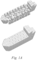
- components from a hull (top) are assembled into a fully connected system-level model (bottom).
- the SCRBE approach to developing parametric ROMs that leverage the component-based decomposition of system-level models introduced above will be described in greater detail below.
- KU F
- F an equilibrium structural analysis FE problem (after discretization based on a finite element space has been applied) posed on ⁇ , such as static or quasi-static linear elasticity.
- K ⁇ R N F E ⁇ N F E is the (symmetric) stiffness matrix
- U ⁇ R N F E is the displacement vector
- F ⁇ R N F E is the load vector
- N F E denotes the number of FE degrees of freedom (DOFs) in the FE discretization on ⁇ .
- the system of (1) may be referred to as the standard FE formulation of this problem, and in the context of ROMs this is often referred to as the "truth" formulation.
- N F E ,1 and N F E ,2 denote the number of FE DOFs associated with the interior (non-port) region of components 1 and 2, respectively, and let N F E , p denote the number of FE DOFs on p .
- DOFs on p may be standard FE Lagrange basis functions associated with individual nodes in the FE mesh, or they may be general functions that have support on the entire port - the latter case is necessary in the case of "port reduction," which will be discuss in greater detail below.
- K U p F .
- K i , i ⁇ 1 there is no explicitly computation of K i , i ⁇ 1 .
- the X vectors in (8) have no physical meaning
- the procedure described above for incorporating a change within a component is indeed modular, but it can be onerous since each change to a component requires a new component-local FE solves to be performed. In practice this may be costly, especially in the case that many updates are required (e.g. when modifications are performed to match real-time sensor measurements, or within the inner loop of an optimization), or when we use highly resolved component meshes.
- the N F E , p ⁇ N F E , p matrix is indeed smaller than (1) since the interior DOFs have been condensed out, but in general (in the case that n comp > 2) it is block-sparse with potentially large and dense blocks with sizes corresponding to the number of port DOFs on component interfaces.
- N F E p + 1 RB bases.
- Z R B i ⁇ R N F E , i ⁇ N R B , i denote an "RB basis function matrix" for component i , where N R B , i denotes the number of RB basis functions, and column j of Z i is the j th basis function.
- EIM empirical interpolation method
- Port reduction vastly increases the applicability of the substructuring framework since we may use ports of any shape or size and locate them anywhere in a model, and as long as we can generate an effective ROM for the ports we will be able to solve the overall model efficiently.
- SCRBE with port reduction for large-scale models we typically obtain orders of magnitude speedup compared to a standard FE solve, whereas with standard substructuring in many cases the solve time for the substructured system is comparable to, or even slower than, the solve time for the standard FE solve, as was noted above.
- Sparse direct solvers are reliable solvers for FE formulations for the types of problems shown below.
- One advantage of a direct solver is that it avoids any convergence issues, but one disadvantage is that it presents significant scalability issues for large-scale problems - especially associated with memory requirements.
- SCRBE with port reduction enables efficient solving of very large-scale models while avoiding convergence difficulties, since - as noted above - it does not require the performance of full order solves at the system level during the Offline stage, and in the Online stage a reduced system may be constructed consisting only of port-reduced-DOFs that is small enough to be solved quickly and efficiently with a direct solver.
- SCRBE resolves a major computational limitation that is present with conventional FE solvers for large-scale structural problems.
- the SCRBE framework presented here combines the RB method on component interiors and port reduction on component interfaces in order to resolve both the first and second issues described above. This enables fast, detailed, and parametric analysis of large-scale systems, which is a set of capabilities that are ideally suited to structural digital twins of industrial systems.
- N m odes eigenvalue/eigenmode pairs of the corresponding eigenvalue problem
- This transformation corresponds to a reduction in the number of interior DOFs on component i due to the truncation of the fixed-interface normal modes, since we typically choose l « N F E,i .
- This DOF transformation can either be applied to (17) directly, or first to the modal problem (18) and then to the dynamic system, as in (20)
- CMS Component Mode Synthesis
- a component-based parametric ROM eigensolver based on SCRBE has previously been developed.
- the next step is to develop an SCREE approximation for (22), which proceeds along the same lines as discussed for Helmholtz problems in above, since the left-hand side matrix in (22) is exactly the H matrix from Section 2.2. Note that, as above, we restrict ⁇ such that ⁇ ⁇ [0, ⁇ c omp ) in order to ensure coercivity and hence stability of the component interior solves for H , and once again this is a modest restriction in practice since typically ⁇ comp corresponds to a high frequency at the system level.
- ROMs component-based ROMs
- flexible multi-body dynamics This approach generalizes rigid multi-body dynamics, in which a system consists of multiple connected rigid components, and is widely used in industrial applications, e.g. in modeling of drive-trains, and robotics.
- components in a rigid-body system may be replaced by ROMs (typically using CMS) that represent the elastic response of the components.
- CMS typically using CMS
- the overall analysis is then geometrically nonlinear due to the finite rotations and translations of each component within the multi-body system, but each flexible component is assumed to have a linear elastic response within its frame of reference.
- nonlinear ROMs such as empirical interpolation (EIM), discrete empirical interpolation (DEIM), or "gappy POD” methods, which enable a full Offline/Online decomposition so that the Online ROM assembly and solve does not depend on N F E .
- EIM empirical interpolation
- DEIM discrete empirical interpolation
- Gappy POD "gappy POD” methods
- Another approach to nonlinear ROMs is machine learning (ML), in which we can non-invasively train ML models based on supervised learning approaches, where a full order solver provides the "truth" data.
- ML machine learning
- non-smooth nonlinearities such as contact analysis and elastoplasticity, in which a small change in applied load can lead to a discrete jump in the contact surface or "plastic front.”
- This type of non-smooth response is inherently difficult for ROMs to resolve, since ROMs rely on construction of a low-dimensional representation of the response, and if the response is non-smooth an accurate low-dimensional representation may not exist (in mathematical terms, the Kolmogorov width of the response may be large, so that efficient model reduction is not possible).
- U h ybrid ⁇ U ⁇ ⁇ U F E , nonlin ⁇ denote the global solution to the Hybrid SCRBE/FE system, where U ⁇ ⁇ R N P R , p is the solution on ⁇ l in , and U F E , nonlin ⁇ R N F E , nonlin is the solution on ⁇ n onlin .
- this defintion of U h ybrid permits discontinuity on the interface of ⁇ n onlin and ⁇ l in so to enforce continuity
- C constraint matrix
- G U h ybrid ⁇ ; ⁇ C T F ⁇ ⁇ ⁇ K ⁇ ⁇ U ⁇ ⁇ G F E , nonlin CU h ybrid ⁇
- G ⁇ ; ⁇ R N P R , p + N F E , nonlin ⁇ R N P R , p + N F E , nonlin denotes the global nonlinear/linear operator on ⁇ , and the C T prefactor ensures that we use the same test functions as trial functions in the spirit of a Galerkin formulation.
- the Hybrid Solver approach has several appealing features. First, it provides the full generality of FE for accurately representing nonlinearities. Second, a digital twin may require multiple separated nonlinear regions, e.g. due to damage or wear or failure in various separated parts of a large system. Due to the nature of the fully-coupled global nonlinear solve, the non-local and cumulative effects of all of these regions are automatically captured by the Hybrid Solver. (In contrast, conventional "submodeling" workflows ignore non-local and cumulative effects.) Third, in the case that we have linear predominance, the Hybrid Solver provides a large computational advantage compared to a full order solve, e.g.
- linear predominance refers to the case where the number of DOFs in the FE region is significantly smaller than the number of full order DOFs in the SCRBE region.
- linear predominance is common in structural digital twin applications, in which often nonlinearities are only required in regions with localized damage or failure, or localized contact regions, for example.
- a global nonlinear FE solve or, if applicable, one of the other nonlinear ROM methods cited above may be implemented.
- a posteriori error assessment is an important ingredient in the SCRBE framework, for checking the accuracy of SCRBE solutions both during the Offline and Online stages. This provides guidance on when to halt Offline training, or when further ROM enrichment is required during the Online stage.
- a posteriori error estimators for the SCRBE method (with port reduction) with respect to the "truth" FE formulation on ⁇ can be developed. Error estimators for SCRBE have also been developed using a residual-based approach, and, in order to make the approach rigorous, a number of constants are computed in order to bound the error in terms of the residual (e.g.
- ⁇ ( ⁇ ) is the SCRBE solution that is reconstructed on the entire system-level domain ⁇ based on a weighted sum of port DOFs and component interior DOFs scaled by coefficients from ⁇ p ( ⁇ ) .
- R ⁇ F ⁇ ⁇ K ⁇ U ⁇ ⁇ .
- ( ⁇ ) can be evaluated in a computationally efficient manner by treating the contribution to the residual from component interiors and ports separately.
- our error indicator ⁇ ( ⁇ ) ⁇ ( ⁇ ) ⁇ / ⁇ F ( ⁇ ) ⁇ , which is the norm of the residual normalized by the norm of the load.
- the use of the SCRBE framework in the methods and systems described herein provides a powerful approach for enabling structural digital twins of large-scale systems. These capabilities are further realized by connecting SCRBE-based models to inspection and sensor data and configuring post-processing for the purposes of automated asset integrity reporting.
- the data flow from operational asset data (e.g., sensors or inspections), to structural digital twin update and analysis, to post-processing and reporting may be referred to as a "digital thread".
- This digital thread may provide asset operators with deep structural integrity insights that leverage the asset data and the SCRBE-based digital twin.
- a method 200 for maintaining a physical asset based on recommendations generated by analyzing a model of the physical asset, the model comprising a plurality of components and forming a physics-based digital twin of the physical asset includes constructing, by a computing device, using a port-reduced static condensation reduced basis element approximation of at least a portion of a partial differential equation, a composite model of a plurality of models, each of the plurality of models representing at least one of a plurality of components, each of the plurality of components representing at least one region of a physical asset (202).
- the method 200 includes analyzing, by the computing device, for at least one model in the plurality of models, an error indicator identifying a level of error associated with the at least one model, to determine that the identified level of error exceeds a tolerance level (204).
- the method 200 includes increasing, by the computing device, a number of basis functions in the port-reduced static condensation reduced basis element approximation, based upon a determination that the at least one model has a level of error exceeding the tolerance level (206).
- the method 200 includes repeating, for each model in the plurality of models, the analyzing of the error indicator and the increasing of the nubmer of basis functions until the level of error for each of the plurality of models is beneath the tolerance level (208).
- the method 200 includes receiving, by the computing device, from a first operational data source associated with the physical asset, first operational data associated with at least one region of the physical asset represented by at least one parameter of at least one component in the plurality of components (210).
- the method 200 includes updating, by the computing device, the composite model, based upon the received first operational data (212).
- the method 200 includes providing, by the computing device, a recommendation for maintaining the physical asset, based upon the updated composite model (214).
- Method 200 therefore, provides an Offline stage that executes a number of steps.
- Method 200 includes specifying a set of training models, , a training tolerance, TOL, and a number of training iterations, .
- Method 200 includes, for each model M ⁇ , performing the following steps: (a) Solve with the current SCRBE ROM and calculate the error indicator ⁇ ( ⁇ ); and (b) If ⁇ ( ⁇ ) > T OL , perform component and port enrichment of the SCRBE ROM, as described above.
- Method 200 includes repeating steps (a) and (b) times, or until ⁇ ⁇ T OL for all M ⁇ .
- the method 200 also includes an Online stage.
- the method 200 solves the system using the SCRBE ROM that was generated in the Offline stage.
- We may optionally also evaluate ⁇ ( ⁇ ) to validate the accuracy of the SCRBE solution, and if we find that ⁇ ( ⁇ ) is larger than desired, we can run further enrichment by revisiting the procedure from the Offline stage when needed - this can be performed in a fully automated manner (driven by the error indicator), or the user may choose to guide if and/or when further enrichment is to be performed.
- the availability of the error indicator provides a robust method for ensuring accuracy of our solutions in the Online stage.
- a method 200 for maintaining a physical asset based on recommendations generated by analyzing a model of the physical asset, the model comprising a plurality of components and forming a physics-based digital twin of the physical asset includes constructing, by a computing device, using a port-reduced static condensation reduced basis element approximation of at least a portion of a partial differential equation, a composite model of a plurality of models, each of the plurality of models representing at least one of a plurality of components, each of the plurality of components representing at least one region of a physical asset (202).
- the computing device 306 may execute an offline component 308 (which may be provided as either a hardware or a software component) that uses the SCRBE framework to construct the composite model of the plurality of models, .
- an offline component 308 (which may be provided as either a hardware or a software component) that uses the SCRBE framework to construct the composite model of the plurality of models, .
- a hybrid solver is used to construct the composite model; in such embodiments, at least a first portion of the partial differential equation is approximated using the SCREE approach while FEA is applied to at least a second portion of the partial differential equation.
- the method 200 includes analyzing, by the computing device, for at least one model in the plurality of models, an error indicator identifying a level of error associated with the at least one model, to determine that the identified level of error exceeds a tolerance level (204).
- the offline component 308 may solve with the current SCRBE ROM and calculate the error indicator.
- the method 200 includes increasing, by the computing device, a number of basis functions in the port-reduced static condensation reduced basis element approximation, based upon a determination that the at least one model has a level of error exceeding the tolerance level (206). If the error indicator is greater than the tolerance level, then the offline component 308 enriches the SCRBE ROM (e.g., adds back in at least one basis function), as described above.
- Basis functions (or degrees of freedom, as they are also described herein) may be added on both interfaces and interior of components.
- Component interior basis functions may be added following the reduced basis greedy algorithm, as described above, in which residual-based a posteriori error bounds in order to guide adaptive sampling in parameter space in order generate efficient RB models that are accurate over the entire parameter domain of interest.
- Component interface basis functions may be added based on adding data that captures the dominant information transfer between adjacent components
- the method 200 includes repeating, for each model in the plurality of models, the analyzing of the error indicator and the increasing of the nubmer of basis functions until the level of error for each of the plurality of models is beneath the tolerance level (208). In one embodiment, the method 200 includes repeating, for each model in the plurality of models, the analyzing of the error indicator and the increasing of the number of basis functions until the level of error for each of the plurality of models is beneath the tolerance level or until a threshold number of iterations is reached. As an example, the method 200 may terminate (208) after determining that the tolerance level is met by each model in the plurality of models. As another example, the method 200 may terminate (208) after a predefined number of iterations; in this way, if each of the plurality of models cannot meet the tolerance level, the method 200 does not continue iterating endlessly.
- (202) - (208) may be referred to as the offline stage.
- (202) - (208) may be performed before the generation of a visual rendering of the composite model.
- (202) - (208) may be performed before the receiving, by the computing device, from the first operational data source associated with the physical asset, first operational data associated with at least one region of the physical asset represented by at least one parameter of at least one component in the plurality of components.
- the method 200 before generating an optional visual rendering of the composite model or receiving operational data, includes receiving user input (e.g., for modeling a "what if" scenario). Therefore, the method 200 may include receiving, by the computing device, first user input identifying an input value indicative of at least one physical condition under which the physical asset is to be evaluated and using, by the computing device, the composite model to generate at least one output value based at least in part on the at least one input value, wherein the at least one output value is indicative of a behavior of the physical system under the at least one physical condition, wherein the at least one output value comprises a plurality of output values over an N-dimensional domain.
- the N-dimensional domain may be a 3-dimensional domain or any other value of N.
- the user input may be any of a variety of input types.
- the user input may identify an input value extracted from an inspection report based on a physical inspection of the physical asset.
- the user input may identify an input value extracted from operational data received from a sensor associated with the physical asset.
- the user input may identify an input value for modeling a component under a particular operational condition, such as to perform fatigue life estimation of critical parts or to perform a strength check based on an industry standard under at least one operational condition.
- the method 200 may include generating, by a simulation tool executed by the computing device, a visual rendering of the composite model including a visualization of at least one result of a physics-based analysis of the physical asset.
- the simulation tool 304 generates the visual rendering of the composite model.
- the simulation tool 304 may generate a visual rendering of the entire composite model, including visualizations of all results of the physics-based analysis of the physical assset.
- the simulation tool 304 may visualization a subset of the resulting values; for example, the simulation tool 304 may visualzation a level of stress at a single weld point as opposed to a level of stress throughout the physical asset.
- the simulation tool 304 (which may be provided as a hardware component or as a software component) may generate the visual rendering.
- the simulation tool 304 may include a user interface with which a user of the system 300 may interact with the visual rendering of the composite model and provide user input.
- the user interface 314 may allow the user to construct a model for a physical system by specifying one or more aspects of the physical system, such as geometry, material, and/or any other suitable physical characteristics.
- the user may, again via the user interface 314, direct the simulation tool 304 to perform a simulation, based on the model to predict how the physical system may behave under one or more selected conditions.
- Results of the simulation may be delivered to the user via the user interface 314 in any suitable manner, such as by visually rendering one or more output values of the simulation. Therefore, an improved simulation tool is provided that allows a user to modify one or more aspects of a physical system and obtain updated simulation results in real time. For instance, user interface functions may be provided for the user to perform various modifications, including, but not limited to, modifying one or more parameters of a component, adding a component (e.g., by cloning an existing component), removing a component, disconnecting previously connected components, moving a component from one part of the physical system to another part of the physical system, and rotating a component. In response to such changes requested by the user, the simulation tool may be able to quickly deliver updated simulation results by leveraging previously computed data.
- the simulation tool may update certain computations relating to components whose parameters and/or connections are changed but may reuse previously computed data for components that are not directly affected by the changes.
- an improved simulation tool may perform one or more consistency checks to determine whether changes requested by a user are compatible with other aspects of a physical system. The simulation tool may alert the user if any incompatibility is detected. Additionally, or alternatively, the simulation tool may propose further changes to the physical system to remove one or more incompatibilities introduced by the user-requested changes.
- an improved simulation tool is provided that automatically computes an error associated with a simulation result.
- an error may be a rigorously computed error bound, such as a maximum possible difference between die simulation result and a result that would have been obtained had a full FEA solution been computed.
- a "local" error bound may be computed for each bubble function, where the local error bound indicates a difference between a reduced order model computed for the bubble function and a corresponding full FEA solution. Such local error bounds may then be combined to obtain an overall error bound for an entire physical system or a portion thereof.
- an error may be an error estimate that can be computed in less time compared to a rigorous error bound.
- a user may choose which type of error (e.g., rigorous error bound or error estimate) is to be computed by the simulation tool.
- the method 200 includes receiving, by the computing device, from a first operational data source associated with the physical asset, first operational data associated with at least one region of the physical asset represented by at least one parameter of at least one component in the plurality of components (210).
- the online component 310 executing on the computing device 306 may receive the first operational data.
- the computing device 306 may receive from the first operational data source associated with the physical asset, first operational data generated by a sensor associated with the physical asset.
- the computing device 306 may receive from the first operational data source associated with the physical asset, first operational data extracted from an inspection report associated with the physical asset; for example, the inspection data may include a result from a visual inspection of an asset (e.g., an observation that there is a crack or corrosion on a pipe and that information should be built into the digital twin).
- the computing device 306 may receive from the first operational data source associated with the physical asset, first operational data extracted from a report generated by an operator of the physical asset.
- the operational data inputs to a digital thread may include the inspection and sensor data available from operational assets. Examples include, without limitation, thickness measurements based on ultrasound thickness gauging; environmental monitoring at specific intervals in time, e.g. wind and wave states for an offshore structure; operational load monitoring, e.g. throughput rates, tank fill levels, and number of loading / unloading cycles per time interval; measurements from structural sensors such as accelerometers and strain gauges; pressure and/or temperature monitoring.
- the method 200 includes updating, by the computing device, the composite model, based upon the received first operational data (212).
- the computing device may identify, within the received first operational data, an input value indicative of at least one physical condition under which the physical asset is to be evaluated and use the composite model to generate at least one output value based at least in part on the at least one input value, wherein the at least one output value is indicative of a behavior of the physical system under the at least one physical condition, wherein the at least one output value comprises a plurality of output values over an N-dimensional domain.
- the computing device may execute an importer application that receives measurement data, formats the data, and updates the model to incorporate measurement data; for example, for thickness measurements, the computing device may receive measurement data in a document including the measurement data in a comma-separated values format (e.g., in a spreadsheet) and may update the SCREE model's thickness to match the imported measurements.
- the computing device may receive the data in an agreed-upon format and incorporate the received data into the SCRBE model.
- Sensor readings may be received in a text format and then importer software may be configured to read the agreed-upon text format and apply the data to the model.
- the computing device may receive an identification of where sensors are installed on a physical asset.
- the computing device may receive an identification of a format for inspection data specifying where in the physical asset each measurement is coming from.
- the formatting may be agreed upon between the operator or owner of the physical asset and the user generating the digital twin when the digital twin is being initially configured so that the digital twin will be configured in a manner consistent with the operational data that will be received.
- the computing device may use the received operational data as an input to the SCRBE model.
- the simulation tool 304 has generated a visual rendering of the composite model.
- the simulation tool 304 may update the visual rendering of the composite model based on updated output values generated by the composite model using the received first operational data.
- the method 200 may include updating the composite model not just once upon receipt of first operational data from a first operational data source but many times upon receipt of a plurality of pieces of operational data from a plurality of operational data sources.
- the digital twin may be constantly updated throughout the online stage in order to keep "in sync" with the physical asset.
- the method 200 may execute steps for updating the model and any optionally generated visual rendering based upon receiving different data from the same operational data source or based upon receiving different data from a different operational data source, or both.
- the method 200 may include receiving, by the computing device, from the first operational data source associated with the physical asset, second operational data associated with the at least one region of the physical asset represented by the at least one parameter of the at least one component in the plurality of components; updating, by the computing device, the composite model, based upon the received second operational data; and providing, by the computing device, a second recommendation for maintaining the physical asset, based upon the updated composite model.
- the simulation tool 304 may update the visual rendering of the composite model based on updated output values generated by the composite model using the received second operational data.
- the method 200 may include receiving, by the computing device, from a second operational data source associated with the physical asset, second operational data associated with at least a second region of the physical asset represented by at least a second parameter of at least a second component in the plurality of components; updating, by the computing device, the composite model, based upon the received second operational data; and providing, by the computing device, a second recommendation for maintaining the physical asset, based upon the updated composite model.
- the simulation tool 304 may update the visual rendering of the composite model based on updated output values generated by the composite model using the received second operational data.
- the method 200 may include updating die Offline stage periodically. Updating may include changing values within at least one model in the plurality of models. Updating may include replacing at least one model in the plurality of models to reflect new operating conditions that have been observed (e.g., by operators generating inspection reports or by sensors generating sensor data).
- the method 200 may include receiving second operational data from the first operational data source; updating at least one model in the plurality of models based upon the received second operational data; analyzing, by the computing device, for at least one model in the plurality of models, an error indicator identifying a level of error associated with the at least one model, to determine whether the identified level of error exceeds a tolerance level; increasing, by the computing device, a number of basis functions in the port-reduced static condensation reduced basis element approximation, based upon a determination that the at least one model has a level of error exceeding the tolerance level; repeating the analyzing of the error indicator and the increasing of the number of basis functions for each model in the plurality of models until the level of error each of the plurality of models is beneath the tolerance level; updating, by the computing device, the composite model, based upon the received data; and providing, by the computing device, a recommendation for maintaining the physical asset, based upon the updated composite model.
- the simulation tool 304 may update the visual rendering of the composite model based on updated output values generated by the composite model using the received second operational data.
- the method 200 may include receiving second operational data from a second operational data source; updating at least one model in the plurality of models based upon die received second operational; analyzing, by the computing device, for at least one model in the plurality of models, an error indicator identifying a level of error associated with the at least one model, to determine whether the identified level of error exceeds a tolerance level; increasing, by the computing device, a number of basis functions in the port-reduced static condensation reduced basis element approximation, based upon a determination that the at least one model has a level of error exceeding the tolerance level; repeating, for each model in die plurality of models, the analyzing of the error indicator and the increasing of the number of basis functions until the level of error each of the plurality of models is beneath the tolerance level; updating, by the computing device, the composite model
- the method 200 includes providing, by the computing device, a recommendation for maintaining the physical asset, based upon the updated composite model (214).
- the system 100 may generate the recommendation based on at least one output value computed by the updated composite model.
- Typical outputs of the digital thread are industry-specific code checks for structural integrity, such as strength, fatigue, and fitness-for-service standards from recognized standards bodies. The calculations required by these standards typically involve post-processing stress data (often based on hundreds or thousands of distinct load cases) in order to calculate quantities such as remaining fatigue estimates or buckling utilization.
- the online component 310 may generate the recommendation for maintaining the physical asset.
- the online component 310 may provide the recommendation to the simulation tool 304 for display to the user via the user interface 314.
- the computing device 306 may provide a recommendation for identifying a plurality of aspects of the physical asset to inspect the plurality of aspects ranked according to a level of priority, based upon the updated composite model.
- the computing device 306 may provide a recommendation for determining a level of feasibility of a proposed modification to the physical asset, based upon the updated composite model.
- the computing device 306 may provide a recommendation for determining at least one operating condition of the physical asset, based upon the updated composite model.
- the user interface 314 may include a dashboard interface in which users can click a button that will run the relevant standards-based checks based on the current state of the digital twin (i.e. incorporating the up-to-date operational data) and generate a report based on the check.
- the report may include one or more recommendations, such as "everything is OK", or "There is an issue with XYZ region of the asset", or "It is not OK to operate the asset in Scenario XYZ”.
- This output can be presented also as a "traffic light” for each asset, e.g. "green light” means all checks passed, "red light” means at least one check failed and indicates that there is something that needs further attention or investigation from the operator, who can then check the full report for details.
- the system 100 includes functionality for transmitting a report including the generated recommendations to another computing device.
- the system 100 includes functionality for implementing a recommendation.
- FIG. 2B a block diagram depicts a visualization of the method 200 resulting in a digital thread for a floating offshore structure.
- Inputs are sensor data and inspection data, which are used to automatically update and analyze the stuctural digital twin. Analysis typically consists of thousands of SCREE solves in order to assess strength and fatigue of the asset in its "as is" state. Once the analysis is complete, reporting based on classification society standards is automatically generated.
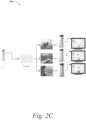
- FIG. 2C a block diagram depicts a visualization of the method 200 resulting in a digital thread for an offshore platform.
- a plurality of accelerometers on a structure e.g., the physical asset
- the method 200 executes and generates automated reporting based on industry standards.
- the SCRBE framework described above provides for the four properties for digital twin modeling that were described above.
- the SCRBE framework resolves issues of costly computing, which, enables systems equivalent to O (10 7 ) or O (10 8 ) FE DOFs to be solved efficiently. This enables holistic and detailed modeling of large-scale structural systems.
- the SCRBE framework statisfies the requirement as a consequence of both the component-local RB models and the port reduction; component-local RB enables fast modifications to a model, and port reduction enables fast system-level solves.
- SCRBE is fundamentally a physics-based method, which is formulated in terms of the same mesh-based approach as FE, except with acceleration due to projection onto a reduced set of port DOFs and component-interior RB DOFs; this means that all of the standards for structural integrity analysis that were typically designed for FE apply directly to SCRBE models.
- the SCRBE-based approach provides all of the key capabilities of digital twins in order to enable the structural digital twin workflows that are of interest for large-scale industrial systems.
- the methods and systems described herein provide functionality for implementing a SCRBE framework that provides powerful and unique capabilities for structural digital twins of large-scale assets.
- An Adaptive ROM Enrichment methodology enables efficient and reliable training of SCRBE models in the Offline stage, as well as accuracy assessment and enrichment guidance (when needed) in the Online stage.
- a range of structural analysis examples demonstrate the scalability, speed, and parametrization capabilities that are enabled by the SCRBE framework and the core concepts of a digital thread built around SCRBE-based structural digital twins were described above.
- the digital thread described herein enables an automated framework that provides operators with deeper structural integrity insights based on the "as is" state of critical assets, and hence empowers safer and more efficient operations.
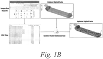
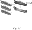
- FIGs. 1B and 1C provide non-limiting examples of the methods and systems described above.
- a block diagram depicts a hull model, updated based upon at least one value within an inspection report.
- the inspection report specifies a thickness for each entity (e.g., plate or stiffener) in the hull, so that a script can automatically update the thicknesses in the corresponding entities in the structural digital twin in order to incorporate the inspection data.
- FIG. 1C a block diagram depicts updated hull models used to generate automated buckling check reports. The figures on the left show each entity in the hull (e.g., plates and stiffened panels).
- FIGs. 4A , 4B , and 4C block diagrams depict additional detail regarding computing devices that may be modified to execution functionality for implementing the methods and systems described above.
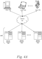
- FIG. 4A an embodiment of a network environment is depicted.
- the network environment comprises one or more clients 102a-102n (also generally referred to as local machine(s) 102, client(s) 102, client node(s) 102, client machine(s) 102, client computer(s) 102, client device(s) 102, computing device(s) 102, endpoint(s) 102, or endpoint node(s) 102) in communication with one or more remote machines 106a-106n (also generally referred to as server(s) 106 or computing device(s) 106) via one or more networks 404.
- clients 102a-102n also generally referred to as local machine(s) 102, client(s) 102, client node(s) 102, client machine(s) 102, client computer(s) 102, client device(s) 102, computing device(s) 102, endpoint(s) 102, or endpoint node(s) 102
- remote machines 106a-106n also generally referred to as server(s) 106 or computing device(s
- FIG. 4A shows a network 404 between the client(s) 102 and the remote machines 106
- the network 404 can be a local area network (LAN), such as a company Intranet, a metropolitan area network (MAN), or a wide area network (WAN), such as the Internet or the World Wide Web.
- LAN local area network
- MAN metropolitan area network
- WAN wide area network
- a network 404' (not shown) may be a private network and a network 404 may be a public network.
- a network 404 may be a private network and a network 404' a public network.
- networks 404 and 404' may both be private networks.
- networks 404 and 404' may both be public networks.
- the network 404 may be any type and/or form of network and may include any of the following: a point to point network, a broadcast network, a wide area network, a local area network, a telecommunications network, a data communication network, a computer network, an ATM (Asynchronous Transfer Mode) network, a SONET (Synchronous Optical Network) network, an SDH (Synchronous Digital Hierarchy) network, a wireless network, and a wireline network.
- the network 404 may comprise a wireless link, such as an infrared channel or satellite band.
- the topology of the network 404 may be a bus, star, or ring network topology.
- the network 404 may be of any such network topology as known to those ordinarily skilled in the art capable of supporting the operations described herein.
- the network 404 may comprise mobile telephone networks utilizing any protocol or protocols used to communicate among mobile devices (including tables and handheld devices generally), including AMPS, TDMA, CDMA, GSM, GPRS, UMTS, or LTE.
- AMPS AMPS
- TDMA Time Division Multiple Access
- CDMA Code Division Multiple Access
- GSM Global System for Mobile communications
- GPRS Global System for Mobile communications
- UMTS Universal Mobile communications
- LTE Long Term Evolution
- different types of data may be transmitted via different protocols.
- the same types of data may be transmitted via different protocols.
- a client(s) 102 and a remote machine 106 can be any workstation, desktop computer, laptop or notebook computer, server, portable computer, mobile telephone, mobile smartphone, or other portable telecommunication device, media playing device, a gaming system, mobile computing device, or any other type and/or form of computing, telecommunications or media device that is capable of communicating on any type and form of network and that has sufficient processor power and memory capacity to perform the operations described herein.
- a client(s) 102 may execute, operate or otherwise provide an application, which can be any type and/or form of software, program, or executable instructions, including, without limitation, any type and/or form of web browser, web-based client, client-server application, an ActiveX control, or a JAVA applet, or any other type and/or form of executable instructions capable of executing on client(s) 102.
- an application can be any type and/or form of software, program, or executable instructions, including, without limitation, any type and/or form of web browser, web-based client, client-server application, an ActiveX control, or a JAVA applet, or any other type and/or form of executable instructions capable of executing on client(s) 102.
- a computing device 106 provides functionality of a web server.
- a web server 106 comprises an open-source web server, such as the NGINX web servers provided by NGINX, Inc., of San Francisco, CA, or the APACHE servers maintained by the Apache Software Foundation of Delaware.
- the web server executes proprietary software, such as the INTERNET INFORMATION SERVICES products provided by Microsoft Corporation of Redmond, WA, the ORACLE IPLANET web server products provided by Oracle Corporation of Redwood Shores, CA, or the BEA WEBLOGIC products provided by BEA Systems of Santa Clara, CA.
- the system may include multiple, logically-grouped remote machines 106.
- the logical group of remote machines may be referred to as a server farm 438.
- the server farm 438 may be administered as a single entity.
- FIGs. 4B and 4C depict block diagrams of a computing device 100 useful for practicing an embodiment of the client(s) 102 or a remote machine 106.
- each computing device 100 includes a central processing unit 421, and a main memory unit 422.
- a computing device 100 may include a storage device 428, an installation device 416, a network interface 418, an I/O controller 423. display devices 424a- n , a keyboard 426, a pointing device 427, such as a mouse, and one or more other I/O devices 430a- n.
- the storage device 428 may include, without limitation, an operating system and software. As shown in FIG.
- each computing device 100 may also include additional optional elements, such as a memory port 403, a bridge 470, one or more input/output devices 430a- n (generally referred to using reference numeral 430), and a cache memory 440 in communication with the central processing unit 421.
- additional optional elements such as a memory port 403, a bridge 470, one or more input/output devices 430a- n (generally referred to using reference numeral 430), and a cache memory 440 in communication with the central processing unit 421.
- the central processing unit 421 is any logic circuitry that responds to and processes instructions fetched from the main memory unit 422.
- the central processing unit 421 is provided by a microprocessor unit, such as: those manufactured by Intel Corporation of Mountain View, CA; those manufactured by Motorola Corporation of Schaumburg, IL; those manufactured by Transmeta Corporation of Santa Clara, CA; those manufactured by International Business Machines of White Plains, NY; or those manufactured by Advanced Micro Devices of Sunnyvale, CA.
- Other examples include SPARC processors, ARM processors, processors used to build UNIX/LINUX "white” boxes, and processors for mobile devices.
- the computing device 400 may be based on any of these processors, or any other processor capable of operating as described herein.
- Main memory unit 422 may be one or more memory chips capable of storing data and allowing any storage location to be directly accessed by the microprocessor 421.
- the main memory 422 may be based on any available memory chips capable of operating as described herein.
- the processor 421 communicates with main memory 422 via a system bus 450.
- FIG. 4C depicts an embodiment of a computing device 400 in which the processor communicates directly with main memory 422 via a memory port 403.
- FIG. 4C also depicts an embodiment in which the main processor 321 communicates directly with cache memory 440 via a secondary bus, sometimes referred to as a backside bus.
- the main processor 421 communicates with cache memory 440 using the system bus 450.
- the processor 421 communicates with various I/O devices 430 via a local system bus 450.
- Various buses may be used to connect the central processing unit 421 to any of the I/O devices 430, including a VESA VL bus, an ISA bus, an EISA bus, a MicroChannel Architecture (MCA) bus, a PCI bus, a PCI-X bus, a PCI-Express bus, or a NuBus.
- MCA MicroChannel Architecture
- PCI bus PCI bus
- PCI-X bus PCI-X bus
- PCI-Express PCI-Express bus
- NuBus NuBus.
- the processor 421 may use an Advanced Graphics Port (AGP) to communicate with the display 424.
- FIG. 4C depicts an embodiment of a computer 400 in which the main processor 421 also communicates directly with an I/O device 430b via, for example, HYPERTRANSPORT, RAPIDIO, or INFINIBAND communications technology.
- I/O devices 430a- n may be present in or connected to the computing device 400, each of which may be of the same or different type and/or form.
- Input devices include keyboards, mice, trackpads, trackballs, microphones, scanners, cameras, and drawing tablets.
- Output devices include video displays, speakers, inkjet printers, laser printers, 3D printers, and dye-sublimation printers.
- the I/O devices may be controlled by an I/O controller 423 as shown in FIG. 4B .
- an I/O device may also provide storage and/or an installation medium 416 for the computing device 400.
- the computing device 400 may provide USB connections (not shown) to receive handheld USB storage devices such as the USB Flash Drive line of devices manufactured by Twintech Industry, Inc. of Los Alamitos, CA.
- the computing device 100 may support any suitable installation device 416, such as a floppy disk drive for receiving floppy disks such as 3.5-inch, 5.25-inch disks or ZIP disks; a CD-ROM drive; a CD-R/RW drive; a DVD-ROM drive; tape drives of various formats; a USB device; a hard-drive or any other device suitable for installing software and programs.
- the computing device 400 may provide functionality for installing software over a network 404.
- the computing device 400 may further comprise a storage device, such as one or more hard disk drives or redundant arrays of independent disks, for storing an operating system and other software.
- the computing device 100 may rely on memory chips for storage instead of hard disks.
- the computing device 400 may include a network interface 418 to interface to the network 404 through a variety of connections including, but not limited to, standard telephone lines, LAN or WAN links (e.g., 802.11, T1, T3, 56kb, X.25, SNA, DECNET), broadband connections (e.g., ISDN, Frame Relay, ATM, Gigabit Ethernet, Ethemet-over-SONET), wireless connections, or some combination of any or all of the above.
- standard telephone lines LAN or WAN links (e.g., 802.11, T1, T3, 56kb, X.25, SNA, DECNET), broadband connections (e.g., ISDN, Frame Relay, ATM, Gigabit Ethernet, Ethemet-over-SONET), wireless connections, or some combination of any or all of the above.
- LAN or WAN links e.g., 802.11, T1, T3, 56kb, X.25, SNA, DECNET
- broadband connections e.g., ISDN, Frame Re
- Connections can be established using a variety of communication protocols (e.g., TCP/IP, IPX, SPX, NetBIOS, Ethernet, ARCNET, SONET, SDH, Fiber Distributed Data Interface (FDDI), RS232, IEEE 802.11, IEEE 802.11a, IEEE 802.11b, IEEE 802.11g, IEEE 802.11n, 802.15.4, Bluetooth, ZIGBEE, CDMA, GSM, WiMax, and direct asynchronous connections).
- the computing device 400 communicates with other computing devices 100' via any type and/or form of gateway or tunneling protocol such as Secure Socket Layer (SSL) or Transport Layer Security (TLS).
- SSL Secure Socket Layer
- TLS Transport Layer Security
- the network interface 418 may comprise a built-in network adapter, network interface card, PCMCTA network card, card bus network adapter, wireless network adapter, USB network adapter, modem, or any other device suitable for interfacing the computing device 100 to any type of network capable of communication and performing the operations described herein.
- an I/O device 430 may be a bridge between the system bus 150 and an external communication bus, such as a USB bus, an Apple Desktop Bus, an RS-232 serial connection, a SCSI bus, a FireWire bus, a FireWire 800 bus, an Ethernet bus, an AppleTalk bus, a Gigabit Ethernet bus, an Asynchronous Transfer Mode bus, a HIPPI bus, a Super HIPPI bus, a SerialPlus bus, a SCI/LAMP bus, a FibreChannel bus, or a Serial Attached small computer system interface bus.
- an external communication bus such as a USB bus, an Apple Desktop Bus, an RS-232 serial connection, a SCSI bus, a FireWire bus, a FireWire 800 bus, an Ethernet bus, an AppleTalk bus, a Gigabit Ethernet bus, an Asynchronous Transfer Mode bus, a HIPPI bus, a Super HIPPI bus, a SerialPlus bus, a SCI/LAMP bus, a FibreChannel bus, or
- a computing device 400 of the sort depicted in FIGs. 4B and 4C typically operates under the control of operating systems, which control scheduling of tasks and access to system resources.
- the computing device 400 can be running any operating system such as any of the versions of the MICROSOFT WINDOWS operating systems, the different releases of the UNIX and LINUX operating systems, any version of the MAC OS for Macintosh computers, any embedded operating system, any real-time operating system, any open source operating system, any proprietary operating system, any operating systems for mobile computing devices, or any other operating system capable of running on the computing device and performing the operations described herein.
- Typical operating systems include, but are not limited to: WINDOWS 3.x, WINDOWS 95, WINDOWS 98, WINDOWS 2000, WINDOWS NT 3.1-4.0, WINDOWS CE, WINDOWS XP, WINDOWS 7, WINDOWS 8, WINDOWS VISTA, and WINDOWS 10, all of which are manufactured by Microsoft Corporation of Redmond, WA; any version of MAC OS manufactured by Apple Inc. of Cupertino, CA; OS/2 manufactured by International Business Machines of Armonk, NY; Red Hat Enterprise Linux, a Linus-variant operating system distributed by Red Hat, Inc., of Raleigh, NC; Ubuntu, a freely-available operating system distributed by Canonical Ltd. of London, England; or any type and/or form of a Unix operating system, among others.
- the computing device 400 can be any workstation, desktop computer, laptop or notebook computer, server, portable computer, mobile telephone or other portable telecommunication device, media playing device, a gaming system, mobile computing device, or any other type and/or form of computing, telecommunications or media device that is capable of communication and that has sufficient processor power and memory capacity to perform the operations described herein.
- the computing device 100 may have different processors, operating systems, and input devices consistent with the device.
- the computing device 400 is a mobile device, such as a JAVA-enabled cellular telephone/smartphone or personal digital assistant (PDA).
- PDA personal digital assistant
- the computing device 400 may be a mobile device such as those manufactured, by way of example and without limitation, by Apple Inc.
- the computing device 100 is a smartphone, POCKET PC, POCKET PC PHONE, or other portable mobile device supporting Microsoft Windows Mobile Software.
- the computing device 400 is a digital audio player.
- the computing device 400 is a digital audio player such as the Apple IPOD, IPOD TOUCH, IPOD NANO, and IPOD SHUFFLE lines of devices manufactured by Apple Inc.
- the digital audio player may function as both a portable media player and as a mass storage device.
- the computing device 100 is a digital audio player such as those manufactured by, for example, and without limitation, Samsung Electronics America of Ridgefield Park, NJ, or Creative Technologies Ltd. of Singapore.
- the computing device 400 is a portable media player or digital audio player supporting file formats including, but not limited to, MP3, WAV, M4A/AAC, WMA Protected AAC, AEFF, Audible audiobook, Apple Lossless audio file formats, and .mov, .m4v, and .mp4 MPEG-4 (H.264/MPEG-4 AVC) video file formats.
- file formats including, but not limited to, MP3, WAV, M4A/AAC, WMA Protected AAC, AEFF, Audible audiobook, Apple Lossless audio file formats, and .mov, .m4v, and .mp4 MPEG-4 (H.264/MPEG-4 AVC) video file formats.
- the computing device 400 includes a combination of devices, such as a mobile phone combined with a digital audio player or portable media player.
- the computing device 100 is a device in the Google/Motorola line of combination digital audio players and mobile phones.
- the computing device 400 is a device in the IPHONE smartphone line of devices manufactured by Apple Inc.
- the computing device 400 is a device executing the ANDROID open source mobile phone platform distributed by the Open Handset Alliance; for example, the device 100 may be a device such as those provided by Samsung Electronics of Seoul, Korea, or HTC Headquarters of Taiwan, R.O.C.
- the computing device 400 is a tablet device such as, for example and without limitation, the IPAD line of devices manufactured by Apple Inc.; the PLAYBOOK manufactured by Research In Motion; die CRUZ line of devices manufactured by Velocity Micro, Inc. of Richmond, VA; the FOLIO and THRIVE line of devices manufactured by Toshiba America Information Systems, Inc. of Irvine, CA; the GALAXY line of devices manufactured by Samsung; the HP SLATE line of devices manufactured by Hewlett-Packard; and the STREAK line of devices manufactured by Dell, Inc. of Round Rock, TX.
- the IPAD line of devices manufactured by Apple Inc. the PLAYBOOK manufactured by Research In Motion
- the GALAXY line of devices manufactured by Samsung the HP SLATE line of devices manufactured by Hewlett-Packard
- a computing device 400 may be a file server, application server, web server, proxy server, appliance, network appliance, gateway, application gateway, gateway server, virtualization server, deployment server, SSL VPN server, or firewall.
- a computing device 400 provides a remote authentication dial-in user service, and is referred to as a RADIUS server.
- a computing device 100 may have the capacity to function as either an application server or as a master application server.
- a computing device 400 is a blade server.
- a computing device 400 may be referred to as a client node, a client machine, an endpoint node, or an endpoint.
- a client 400 has the capacity to function as both a client node seeking access to resources provided by a server and as a server node providing access to hosted resources for other clients.
- a first, client computing device 400a communicates with a second, server computing device 400b.
- the client communicates with one of the computing devices 400 in a server farm. Over the network, the client can, for example, request execution of various applications hosted by the computing devices 400 in the server farm and receive output data of the results of the application execution for display.
Landscapes
- Engineering & Computer Science (AREA)
- Physics & Mathematics (AREA)
- Theoretical Computer Science (AREA)
- General Physics & Mathematics (AREA)
- Business, Economics & Management (AREA)
- Geometry (AREA)
- General Engineering & Computer Science (AREA)
- Economics (AREA)
- Human Resources & Organizations (AREA)
- Computer Hardware Design (AREA)
- Evolutionary Computation (AREA)
- Strategic Management (AREA)
- Entrepreneurship & Innovation (AREA)
- Chemical & Material Sciences (AREA)
- Combustion & Propulsion (AREA)
- Mechanical Engineering (AREA)
- Ocean & Marine Engineering (AREA)
- Development Economics (AREA)
- Tourism & Hospitality (AREA)
- Operations Research (AREA)
- Quality & Reliability (AREA)
- General Business, Economics & Management (AREA)
- Marketing (AREA)
- Pure & Applied Mathematics (AREA)
- Automation & Control Theory (AREA)
- Aviation & Aerospace Engineering (AREA)
- Mathematical Optimization (AREA)
- Mathematical Analysis (AREA)
- Computational Mathematics (AREA)
- Game Theory and Decision Science (AREA)
- Computer Graphics (AREA)
- Fluid Mechanics (AREA)
- Educational Administration (AREA)
- Accounting & Taxation (AREA)
- Finance (AREA)
- Management, Administration, Business Operations System, And Electronic Commerce (AREA)
- Complex Calculations (AREA)
- Image Generation (AREA)
- Stored Programmes (AREA)
Claims (15)
- Verfahren zum Erhalten einer physischen Anlage basierend auf Empfehlungen, die durch Analysieren eines Modells der physischen Anlage erzeugt werden, wobei das Modell mehrere Komponenten umfasst und einen auf Physik basierenden digitalen Zwilling der physischen Anlage bildet, wobei das Verfahren Folgendes umfasst:(a) Konstruieren, durch eine Datenverarbeitungsvorrichtung, unter Verwendung einer Annäherung eines durch portreduzierte statische Kondensation reduzierten Basiselements, zumindest eines Teils einer partiellen Differentialgleichung, eines zusammengesetzten Modells aus mehreren Modellen, wobei jedes der mehreren Modelle zumindest eine von mehreren Komponenten darstellt, wobei jede der mehreren Komponenten zumindest eine Region der physischen Anlage darstellt;(b) Analysieren, durch die Datenverarbeitungsvorrichtung, für zumindest ein Modell in den mehreren Modellen, eines Fehlerindikators, der ein Fehlerniveau in Verbindung mit dem zumindest einen Modell identifiziert, um zu bestimmen, dass das identifizierte Fehlerniveau ein Toleranzniveau überschreitet;(c) Erhöhen, durch die Datenverarbeitungsvorrichtung, einer Anzahl von Basisfunktionen in der Annäherung eines durch portreduzierte statische Kondensation reduzierten Basiselements, basierend auf einer Bestimmung, dass das zumindest eine Modell ein Fehlerniveau aufweist, das das Toleranzniveau überschreitet;(d) Wiederholen von (b) und (c) für jedes Modell in den mehreren Modellen, bis das Fehlerniveau für jedes der mehreren Modelle unter dem Toleranzniveau ist;(e) Empfangen, durch die Datenverarbeitungsvorrichtung, von einer ersten Betriebsdatenquelle in Verbindung mit der physischen Anlage, von ersten Betriebsdaten in Verbindung mit zumindest einer Region der physischen Anlage, repräsentiert durch zumindest einen Parameter zumindest einer Komponenten in den mehreren Komponenten, wobei die ersten Betriebsdaten von einem Sensor in Verbindung mit der physischen Anlage empfangen werden;(f) Aktualisieren, durch die Datenverarbeitungsvorrichtung, des zusammengesetzten Modells, basierend auf den empfangenen ersten Betriebsdaten; und(g) Bereitstellen, durch die Datenverarbeitungsvorrichtung, einer Empfehlung zum Erhalten der physischen Anlage, basierend auf dem aktualisierten zusammengesetzten Modell, wobei die Empfehlung mehrere zu inspizierende Aspekte der physischen Anlage identifiziert, wobei die mehreren Aspekte entsprechend einem Prioritätsniveau basierend auf dem aktualisierten zusammengesetzten Modell sortiert werden.
- Verfahren nach Anspruch 1, wobei (a)-(d) vor (e) durchgeführt werden.
- Verfahren nach Anspruch 1, ferner umfassend, nach (a)-(d) und vor (e), Erzeugen einer auf Physik basierenden Analyse der physischen Anlage unter Verwendung des zusammengesetzten Modells, wobei Erzeugen ferner Folgendes umfasst:Empfangen, durch die Datenverarbeitungsvorrichtung, einer ersten Benutzereingabe, die einen Eingabewert identifiziert, der indikativ für zumindest eine physikalische Bedingung ist, unter der die physische Anlage zu evaluieren ist; undVerwenden, durch die Datenverarbeitungsvorrichtung, des zusammengesetzten Modells zum Erzeugen zumindest eines Ausgabewerts zumindest teilweise basierend auf dem zumindest einen Eingabewert, wobei der zumindest eine Ausgabewert indikativ für ein Verhalten des physischen Systems unter der zumindest einen physikalischen Bedingung ist, wobei der zumindest eine Ausgabewert mehrere Ausgabewerte über einer N-dimensionalen Domäne umfasst.
- Verfahren nach Anspruch 3, wobei Empfangen ferner Empfangen, durch die Datenverarbeitungsvorrichtung, einer Benutzereingabe umfasst, die einen Eingabewert identifiziert, der aus einem Inspektionsbericht extrahiert wird, basierend auf einer physischen Inspektion der physischen Anlage.
- Verfahren nach Anspruch 3, wobei Empfangen ferner Empfangen, durch die Datenverarbeitungsvorrichtung, einer Benutzereingabe umfasst, die einen Eingabewert identifiziert, der aus Betriebsdaten extrahiert wird, die von einem Sensor in Verbindung mit der physischen Anlage empfangen wurden.
- Verfahren nach Anspruch 1, das ferner Folgendes umfasst: (h) Erzeugen, durch ein Simulationsprogramm, das durch die Datenverarbeitungsvorrichtung ausgeführt wird, einer visuellen Darstellung des zusammengesetzten Modells, umfassend eine Visualisierung von zumindest einem Ergebnis einer auf Physik basierenden Analyse der physischen Anlage.
- Verfahren nach Anspruch 6, das ferner Folgendes umfasst: (i) Aktualisieren, durch das Simulationsprogramm, der visuellen Darstellung basierend auf den empfangenen ersten Betriebsdaten.
- Verfahren nach Anspruch 1, wobei (d) Wiederholen von (b) und (c) für jedes Modell in den mehreren Modellen umfasst, bis eine Schwellenanzahl von Iterationen erreicht ist.
- Verfahren nach Anspruch 1, wobei (e) ferner Empfangen, durch die Datenverarbeitungsvorrichtung, von der ersten Betriebsdatenquelle in Verbindung mit der physischen Anlage, von ersten Betriebsdaten umfasst, die durch einen Sensor in Verbindung mit der physischen Anlage empfangen wurden.
- Verfahren nach Anspruch 1, wobei (e) ferner Empfangen, durch die Datenverarbeitungsvorrichtung, von der ersten Betriebsdatenquelle in Verbindung mit der physischen Anlage, von ersten Betriebsdaten umfasst, die aus einem Inspektionsbericht in Verbindung mit der physischen Anlage extrahiert wurden.
- Verfahren nach Anspruch 1 wobei (e) ferner Empfangen, durch die Datenverarbeitungsvorrichtung, von der ersten Betriebsdatenquelle in Verbindung mit der physischen Anlage, von ersten Betriebsdaten umfasst, die aus einem durch einen Bediener der physischen Anlage erzeugten Bericht extrahiert wurden.
- Verfahren nach Anspruch 1, das ferner Folgendes umfasst:
(h) Bereitstellen, durch die Datenverarbeitungsvorrichtung, einer Empfehlung zum Bestimmen eines Umsetzbarkeitsniveaus einer vorgeschlagenen Modifikation der physischen Anlage und/oder einer Empfehlung zum Bestimmen eines Betreibbarkeitsniveaus der physischen Anlage basierend auf dem aktualisierten zusammengesetzten Modell. - Verfahren nach Anspruch 1, das ferner Folgendes umfasst:(h) Empfangen, durch die Datenverarbeitungsvorrichtung, von der ersten Betriebsdatenquelle in Verbindung mit der physischen Anlage, von zweiten Betriebsdaten in Verbindung mit der zumindest einen Region der physischen Anlage, repräsentiert durch den zumindest einen Parameter der zumindest einen Komponente in den mehreren Komponenten;(i) Aktualisieren, durch die Datenverarbeitungsvorrichtung, des zusammengesetzten Modells, basierend auf den zweiten Betriebsdaten; und(j) Bereitstellen, durch die Datenverarbeitungsvorrichtung, einer zweiten Empfehlung zum Erhalten der physischen Anlage basierend auf dem aktualisierten zusammengesetzten Modell.
- Verfahren nach Anspruch 1, das ferner Folgendes umfasst:(h) Empfangen, durch die Datenverarbeitungsvorrichtung, von einer zweiten Betriebsdatenquelle in Verbindung mit der physischen Anlage, von zweiten Betriebsdaten in Verbindung mit zumindest einer zweiten Region der physischen Anlage, repräsentiert durch zumindest einen zweiten Parameter zumindest einer zweiten Komponente in den mehreren Komponenten;(i) Aktualisieren, durch die Datenverarbeitungsvorrichtung, des zusammengesetzten Modells, basierend auf den zweiten Betriebsdaten; und(j) Bereitstellen, durch die Datenverarbeitungsvorrichtung, einer zweiten Empfehlung zum Erhalten der physischen Anlage basierend auf dem aktualisierten zusammengesetzten Modell.
- Nicht-flüchtiges, computerlesbares Medium, codiert mit computerausführbaren Anweisungen, die, wenn auf einer Datenverarbeitungsvorrichtung ausgeführt, die Datenverarbeitungsvorrichtung veranlassen, das Verfahren nach einem der vorhergehenden Ansprüche auszuführen.
Applications Claiming Priority (2)
| Application Number | Priority Date | Filing Date | Title |
|---|---|---|---|
| US16/694,080 US11433977B2 (en) | 2019-11-25 | 2019-11-25 | Methods and systems for component-based reduced order modeling for industrial-scale structural digital twins |
| PCT/IB2020/060441 WO2021105803A1 (en) | 2019-11-25 | 2020-11-06 | Methods and systems for component-based reduced order modeling for industrial-scale structural digital twins |
Publications (3)
| Publication Number | Publication Date |
|---|---|
| EP4066178A1 EP4066178A1 (de) | 2022-10-05 |
| EP4066178C0 EP4066178C0 (de) | 2024-09-11 |
| EP4066178B1 true EP4066178B1 (de) | 2024-09-11 |
Family
ID=73449127
Family Applications (1)
| Application Number | Title | Priority Date | Filing Date |
|---|---|---|---|
| EP20807508.5A Active EP4066178B1 (de) | 2019-11-25 | 2020-11-06 | Verfahren und systeme zur komponentenbasierten modellierung reduzierter ordnung für strukturelle digitale zwillinge im industriellen massstab |
Country Status (10)
| Country | Link |
|---|---|
| US (1) | US11433977B2 (de) |
| EP (1) | EP4066178B1 (de) |
| JP (1) | JP7564204B2 (de) |
| KR (1) | KR20220101192A (de) |
| CN (1) | CN114830152A (de) |
| AU (1) | AU2020392984A1 (de) |
| BR (1) | BR112022009044A2 (de) |
| CA (1) | CA3157791A1 (de) |
| ES (1) | ES2988866T3 (de) |
| WO (1) | WO2021105803A1 (de) |
Families Citing this family (31)
| Publication number | Priority date | Publication date | Assignee | Title |
|---|---|---|---|---|
| US12326717B2 (en) | 2019-11-25 | 2025-06-10 | Akselos S.A. | Methods and systems for component-based reduced order modeling for industrial-scale structural digital twins |
| US11727162B2 (en) | 2019-11-25 | 2023-08-15 | Akselos S.A. | Methods and systems for component-based reduced order modeling for industrial-scale structural digital twins |
| US11433977B2 (en) | 2019-11-25 | 2022-09-06 | Akselos S.A. | Methods and systems for component-based reduced order modeling for industrial-scale structural digital twins |
| US11874200B2 (en) * | 2020-09-08 | 2024-01-16 | International Business Machines Corporation | Digital twin enabled equipment diagnostics based on acoustic modeling |
| CN112528533B (zh) * | 2020-11-19 | 2022-02-25 | 中国矿业大学 | 一种千米深井提升机制动器可靠性智能评估与寿命预测方法 |
| US20220382922A1 (en) * | 2021-05-25 | 2022-12-01 | International Business Machines Corporation | Digital twin objects for product packaging compatibility |
| CN113283017A (zh) * | 2021-06-25 | 2021-08-20 | 宝能(广州)汽车研究院有限公司 | 一种零件分离方法、装置、设备及存储介质 |
| CN113283000B (zh) * | 2021-06-29 | 2022-11-11 | 四川农业大学 | 一种基于有限元和检监测数据融合的全桥响应重构方法 |
| CN113569475B (zh) * | 2021-07-21 | 2023-09-01 | 上海工程技术大学 | 一种基于数字孪生技术的地铁轴箱轴承故障诊断系统 |
| CN113792376A (zh) * | 2021-08-20 | 2021-12-14 | 合众新能源汽车有限公司 | 电池包振动疲劳的分析方法及装置 |
| CN113792422B (zh) * | 2021-09-04 | 2023-12-05 | 苏州特比姆智能科技有限公司 | 一种基于数字孪生的tpm设备管理虚拟验证方法及系统 |
| US20240411279A1 (en) * | 2021-09-17 | 2024-12-12 | Trustees Of Tufts College | Systems and methods for managing complex systems |
| CN113788122B (zh) * | 2021-10-28 | 2022-08-16 | 江南造船(集团)有限责任公司 | 集装箱船船体有限元分析前处理方法 |
| CN113971360B (zh) * | 2021-11-08 | 2025-04-11 | 重庆邮电大学 | 一种基于数字孪生模型的组件状态估计方法 |
| US12131134B1 (en) | 2021-12-17 | 2024-10-29 | Auburn University | Physical components using data element mapping and analysis |
| CN114326492B (zh) * | 2021-12-20 | 2023-09-01 | 中国科学院上海高等研究院 | 一种流程工业设备的数字孪生虚实联动系统 |
| KR102733941B1 (ko) * | 2021-12-22 | 2024-11-25 | 포항공과대학교 산학협력단 | 선형 투영 및 비선형 투영 방식을 혼합한 차수 감축 모델 구축 방법 |
| JP7194295B1 (ja) | 2022-02-15 | 2022-12-21 | 上銀科技股▲分▼有限公司 | デジタルツインモデルを構築する方法 |
| EP4254085A1 (de) * | 2022-03-30 | 2023-10-04 | Siemens Aktiengesellschaft | Verfahren zur modellierung eines industriellen systems und vorrichtung zur steuerung und/oder überwachung eines industriellen systems |
| CN114626278B (zh) * | 2022-05-16 | 2022-08-05 | 湖南大学 | 一种用于动力电池托架结构性能评估和健康监测的方法 |
| EP4290074A1 (de) * | 2022-06-09 | 2023-12-13 | Akselos S.A. | Verfahren und system zur modellierung einer windenergieerzeugungsstruktur |
| CN115292814B (zh) * | 2022-07-28 | 2025-03-25 | 东风汽车集团股份有限公司 | 扭力梁优化设计方法及车辆 |
| CN115423165B (zh) * | 2022-08-24 | 2025-12-12 | 国网江苏省电力有限公司南京供电分公司 | 一种数字孪生引擎中资产价值模型的构建方法及系统 |
| KR102916348B1 (ko) | 2022-09-05 | 2026-01-22 | 한국전자통신연구원 | 다종의 데이터 및 디지털 트윈 동작의 유효성 검증 장치 및 그 방법 |
| CN115758615B (zh) * | 2022-11-26 | 2024-03-12 | 宝钢工程技术集团有限公司 | 一种基于连铸设备有限元仿真模型的数字孪生实现方法 |
| CN116050257A (zh) * | 2022-12-28 | 2023-05-02 | 厦门大学 | 面向自我意识增强的无人机数字孪生体模块化仿真方法 |
| CN116029178B (zh) * | 2023-03-29 | 2023-08-18 | 长安新能源南京研究院有限公司 | 一种模型建立方法、装置、电子设备及存储介质 |
| CN116588347B (zh) * | 2023-04-21 | 2025-12-12 | 清华大学 | 航空复合材料修复数字孪生体与智能抢修方法、系统 |
| CN117592310B (zh) * | 2024-01-17 | 2024-04-02 | 苏州数算软云科技有限公司 | 支撑结构数字孪生模型的更新方法、装置、设备以及介质 |
| CN119167551B (zh) * | 2024-09-02 | 2025-08-15 | 深圳市玉井精密五金有限公司 | 一种非标准精密零部件生产的方法及系统 |
| CN119047376B (zh) * | 2024-10-24 | 2025-05-30 | 菏泽市产品检验检测研究院 | 一种基于数字孪生的压力容器安全评价预警方法 |
Family Cites Families (27)
| Publication number | Priority date | Publication date | Assignee | Title |
|---|---|---|---|---|
| US4858146A (en) | 1986-08-13 | 1989-08-15 | The Babcock & Wilcox Company | Automated design of structures using a finite element database |
| US5442569A (en) | 1993-06-23 | 1995-08-15 | Oceanautes Inc. | Method and apparatus for system characterization and analysis using finite element methods |
| WO2000060540A1 (en) | 1999-04-07 | 2000-10-12 | Cadence Design Systems, Inc. | Method and system for modeling time-varying systems and non-linear systems |
| US9208270B2 (en) | 2000-08-02 | 2015-12-08 | Comsol Ab | System and method for establishing bidirectional links between multiphysics modeling and design systems |
| US7596474B2 (en) | 2000-08-02 | 2009-09-29 | Comsol Ab | Method for assembling the finite element discretization of arbitrary weak equations involving local or non-local multiphysics couplings |
| US20040236450A1 (en) | 2000-09-25 | 2004-11-25 | Motorwiz, Inc. | Model-based machine diagnostics and prognostics using theory of noise and communications |
| DE10237310B4 (de) | 2002-08-14 | 2006-11-30 | Wismüller, Axel, Dipl.-Phys. Dr.med. | Verfahren, Datenverarbeitungseinrichtung und Computerprogrammprodukt zur Datenverarbeitung |
| US9818136B1 (en) | 2003-02-05 | 2017-11-14 | Steven M. Hoffberg | System and method for determining contingent relevance |
| US7328128B2 (en) | 2006-02-22 | 2008-02-05 | General Electric Company | Method, system, and computer program product for performing prognosis and asset management services |
| US8046200B2 (en) * | 2006-09-05 | 2011-10-25 | Colorado State University Research Foundation | Nonlinear function approximation over high-dimensional domains |
| US8375343B1 (en) | 2008-04-11 | 2013-02-12 | Cadence Design Systems, Inc. | Methods and apparatus for waveform based variational static timing analysis |
| US8036759B2 (en) * | 2008-04-30 | 2011-10-11 | Exxonmobil Chemical Patents Inc. | Online modular parameterization and successive linear programming for improving manufacturing plant operations |
| US20090322739A1 (en) | 2008-06-27 | 2009-12-31 | Microsoft Corporation | Visual Interactions with Analytics |
| US8531451B2 (en) | 2009-06-19 | 2013-09-10 | Microsoft Corporation | Data-driven visualization transformation |
| US8352397B2 (en) | 2009-09-10 | 2013-01-08 | Microsoft Corporation | Dependency graph in data-driven model |
| US9213788B2 (en) | 2011-10-25 | 2015-12-15 | Massachusetts Institute Of Technology | Methods and apparatus for constructing and analyzing component-based models of engineering systems |
| US9703902B2 (en) * | 2013-05-09 | 2017-07-11 | Rockwell Automation Technologies, Inc. | Using cloud-based data for industrial simulation |
| CN103984813B (zh) * | 2014-05-09 | 2017-06-06 | 西安交通大学 | 一种离心压缩机裂纹叶轮结构的振动建模与分析方法 |
| WO2017091339A1 (en) | 2015-11-25 | 2017-06-01 | International Business Machines Corporation | Tool to provide integrated circuit masks with accurate dimensional compensation of patterns |
| US20170286572A1 (en) * | 2016-03-31 | 2017-10-05 | General Electric Company | Digital twin of twinned physical system |
| US20180137219A1 (en) * | 2016-11-14 | 2018-05-17 | General Electric Company | Feature selection and feature synthesis methods for predictive modeling in a twinned physical system |
| US20180373820A1 (en) | 2017-06-26 | 2018-12-27 | Akselos S.A. | Methods and Systems for Constructing and Analyzing Component-Based Models of Engineering Systems Having Linear and Nonlinear Regions |
| US11694094B2 (en) * | 2018-03-21 | 2023-07-04 | Swim.IT Inc | Inferring digital twins from captured data |
| CN109445305A (zh) * | 2018-10-26 | 2019-03-08 | 中国电子科技集团公司第三十八研究所 | 一种基于数字孪生的装配精度仿真分析方法与系统 |
| CN109933923B (zh) * | 2019-03-19 | 2022-12-02 | 山东大学 | 一种基于数字孪生的机电装备精益设计方法 |
| US11727162B2 (en) | 2019-11-25 | 2023-08-15 | Akselos S.A. | Methods and systems for component-based reduced order modeling for industrial-scale structural digital twins |
| US11433977B2 (en) | 2019-11-25 | 2022-09-06 | Akselos S.A. | Methods and systems for component-based reduced order modeling for industrial-scale structural digital twins |
-
2019
- 2019-11-25 US US16/694,080 patent/US11433977B2/en active Active
-
2020
- 2020-11-06 ES ES20807508T patent/ES2988866T3/es active Active
- 2020-11-06 AU AU2020392984A patent/AU2020392984A1/en active Pending
- 2020-11-06 EP EP20807508.5A patent/EP4066178B1/de active Active
- 2020-11-06 CA CA3157791A patent/CA3157791A1/en active Pending
- 2020-11-06 WO PCT/IB2020/060441 patent/WO2021105803A1/en not_active Ceased
- 2020-11-06 KR KR1020227021412A patent/KR20220101192A/ko active Pending
- 2020-11-06 BR BR112022009044A patent/BR112022009044A2/pt unknown
- 2020-11-06 JP JP2022524941A patent/JP7564204B2/ja active Active
- 2020-11-06 CN CN202080081731.7A patent/CN114830152A/zh active Pending
Also Published As
| Publication number | Publication date |
|---|---|
| WO2021105803A1 (en) | 2021-06-03 |
| BR112022009044A2 (pt) | 2022-08-09 |
| JP7564204B2 (ja) | 2024-10-08 |
| AU2020392984A1 (en) | 2022-05-19 |
| US11433977B2 (en) | 2022-09-06 |
| JP2023502325A (ja) | 2023-01-24 |
| CA3157791A1 (en) | 2021-06-03 |
| US20210155325A1 (en) | 2021-05-27 |
| EP4066178C0 (de) | 2024-09-11 |
| CN114830152A (zh) | 2022-07-29 |
| EP4066178A1 (de) | 2022-10-05 |
| ES2988866T3 (es) | 2024-11-22 |
| KR20220101192A (ko) | 2022-07-19 |
Similar Documents
| Publication | Publication Date | Title |
|---|---|---|
| EP4066178B1 (de) | Verfahren und systeme zur komponentenbasierten modellierung reduzierter ordnung für strukturelle digitale zwillinge im industriellen massstab | |
| US11727162B2 (en) | Methods and systems for component-based reduced order modeling for industrial-scale structural digital twins | |
| Dang et al. | Cloud-based digital twinning for structural health monitoring using deep learning | |
| US12326717B2 (en) | Methods and systems for component-based reduced order modeling for industrial-scale structural digital twins | |
| Sadhu et al. | A review of data management and visualization techniques for structural health monitoring using BIM and virtual or augmented reality | |
| Kang et al. | Multimedia knowledge‐based bridge health monitoring using digital twin | |
| Sharma et al. | RB-FEA based digital twin for structural integrity assessment of offshore structures | |
| US20240135064A1 (en) | Methods and systems for component-based reduced order modeling for industrial-scale structural digital twins | |
| Podskarbi et al. | Digital twin for operations-present applications and future digital thread | |
| Chacón et al. | Digital twinning during load tests of railway bridges-case study: the high-speed railway network, Extremadura, Spain | |
| Rios et al. | Synthetic data generation for the creation of bridge digital twins what-if scenarios | |
| Wimmer et al. | Digital twins for engineering structures—An Industry 4.0 perspective | |
| Reza et al. | Digital twins for electric propulsion technologies | |
| Wang et al. | Quantum‐Classical Hybrid Genetic Evolutionary Algorithm for Topology Optimization of Continuum Structures | |
| Giri et al. | Bayesian-based multi-class damage identification on prestressed reinforced concrete bridges | |
| Ma et al. | Bridging the Reality Gap in Digital Twins with Context-Aware: Physics-Guided Deep Learning | |
| Cheng et al. | Modeling and simulation of sheet-metal part deformation in virtual assembly | |
| Liu et al. | Reliability analysis of structures by iterative improved ensemble of surrogate method | |
| Kobayashi et al. | When network architecture meets physics: Deep operator learning for coupled multiphysics | |
| Talasila et al. | Structural health monitoring of engineering structures using digital twins: A digital twin platform approach | |
| Sapkota | Adaptive simulation modelling using the Digital Twin paradigm | |
| Liu et al. | A New Formulation on Seismic Risk Assessment for Reinforced Concrete Structures with Both Random and Bounded Uncertainties | |
| Rothblatt | Level of Fidelity Adaptation of Structural Models to Support In-Space Servicing, Assembly, and Manufacturing (ISAM) | |
| Thakur et al. | Real-Time Multi-Modal SHM Framework For Complex Infrastructure | |
| Tian et al. | Exact Dirichlet boundary multi‐resolution hash encoding solver for structures |
Legal Events
| Date | Code | Title | Description |
|---|---|---|---|
| STAA | Information on the status of an ep patent application or granted ep patent |
Free format text: STATUS: UNKNOWN |
|
| STAA | Information on the status of an ep patent application or granted ep patent |
Free format text: STATUS: THE INTERNATIONAL PUBLICATION HAS BEEN MADE |
|
| PUAI | Public reference made under article 153(3) epc to a published international application that has entered the european phase |
Free format text: ORIGINAL CODE: 0009012 |
|
| STAA | Information on the status of an ep patent application or granted ep patent |
Free format text: STATUS: REQUEST FOR EXAMINATION WAS MADE |
|
| 17P | Request for examination filed |
Effective date: 20220429 |
|
| AK | Designated contracting states |
Kind code of ref document: A1 Designated state(s): AL AT BE BG CH CY CZ DE DK EE ES FI FR GB GR HR HU IE IS IT LI LT LU LV MC MK MT NL NO PL PT RO RS SE SI SK SM TR |
|
| DAV | Request for validation of the european patent (deleted) | ||
| DAX | Request for extension of the european patent (deleted) | ||
| GRAP | Despatch of communication of intention to grant a patent |
Free format text: ORIGINAL CODE: EPIDOSNIGR1 |
|
| STAA | Information on the status of an ep patent application or granted ep patent |
Free format text: STATUS: GRANT OF PATENT IS INTENDED |
|
| INTG | Intention to grant announced |
Effective date: 20240404 |
|
| GRAS | Grant fee paid |
Free format text: ORIGINAL CODE: EPIDOSNIGR3 |
|
| GRAA | (expected) grant |
Free format text: ORIGINAL CODE: 0009210 |
|
| STAA | Information on the status of an ep patent application or granted ep patent |
Free format text: STATUS: THE PATENT HAS BEEN GRANTED |
|
| AK | Designated contracting states |
Kind code of ref document: B1 Designated state(s): AL AT BE BG CH CY CZ DE DK EE ES FI FR GB GR HR HU IE IS IT LI LT LU LV MC MK MT NL NO PL PT RO RS SE SI SK SM TR |
|
| REG | Reference to a national code |
Ref country code: GB Ref legal event code: FG4D |
|
| REG | Reference to a national code |
Ref country code: CH Ref legal event code: EP |
|
| REG | Reference to a national code |
Ref country code: DE Ref legal event code: R096 Ref document number: 602020037643 Country of ref document: DE |
|
| REG | Reference to a national code |
Ref country code: IE Ref legal event code: FG4D |
|
| U01 | Request for unitary effect filed |
Effective date: 20240915 |
|
| U07 | Unitary effect registered |
Designated state(s): AT BE BG DE DK EE FI FR IT LT LU LV MT NL PT RO SE SI Effective date: 20241007 |
|
| REG | Reference to a national code |
Ref country code: ES Ref legal event code: FG2A Ref document number: 2988866 Country of ref document: ES Kind code of ref document: T3 Effective date: 20241122 |
|
| U20 | Renewal fee for the european patent with unitary effect paid |
Year of fee payment: 5 Effective date: 20241105 |
|
| PG25 | Lapsed in a contracting state [announced via postgrant information from national office to epo] |
Ref country code: GR Free format text: LAPSE BECAUSE OF FAILURE TO SUBMIT A TRANSLATION OF THE DESCRIPTION OR TO PAY THE FEE WITHIN THE PRESCRIBED TIME-LIMIT Effective date: 20241212 |
|
| PG25 | Lapsed in a contracting state [announced via postgrant information from national office to epo] |
Ref country code: HR Free format text: LAPSE BECAUSE OF FAILURE TO SUBMIT A TRANSLATION OF THE DESCRIPTION OR TO PAY THE FEE WITHIN THE PRESCRIBED TIME-LIMIT Effective date: 20240911 |
|
| PG25 | Lapsed in a contracting state [announced via postgrant information from national office to epo] |
Ref country code: RS Free format text: LAPSE BECAUSE OF FAILURE TO SUBMIT A TRANSLATION OF THE DESCRIPTION OR TO PAY THE FEE WITHIN THE PRESCRIBED TIME-LIMIT Effective date: 20241211 |
|
| PG25 | Lapsed in a contracting state [announced via postgrant information from national office to epo] |
Ref country code: RS Free format text: LAPSE BECAUSE OF FAILURE TO SUBMIT A TRANSLATION OF THE DESCRIPTION OR TO PAY THE FEE WITHIN THE PRESCRIBED TIME-LIMIT Effective date: 20241211 Ref country code: HR Free format text: LAPSE BECAUSE OF FAILURE TO SUBMIT A TRANSLATION OF THE DESCRIPTION OR TO PAY THE FEE WITHIN THE PRESCRIBED TIME-LIMIT Effective date: 20240911 Ref country code: GR Free format text: LAPSE BECAUSE OF FAILURE TO SUBMIT A TRANSLATION OF THE DESCRIPTION OR TO PAY THE FEE WITHIN THE PRESCRIBED TIME-LIMIT Effective date: 20241212 |
|
| PG25 | Lapsed in a contracting state [announced via postgrant information from national office to epo] |
Ref country code: IS Free format text: LAPSE BECAUSE OF FAILURE TO SUBMIT A TRANSLATION OF THE DESCRIPTION OR TO PAY THE FEE WITHIN THE PRESCRIBED TIME-LIMIT Effective date: 20250111 |
|
| PG25 | Lapsed in a contracting state [announced via postgrant information from national office to epo] |
Ref country code: SM Free format text: LAPSE BECAUSE OF FAILURE TO SUBMIT A TRANSLATION OF THE DESCRIPTION OR TO PAY THE FEE WITHIN THE PRESCRIBED TIME-LIMIT Effective date: 20240911 |
|
| PG25 | Lapsed in a contracting state [announced via postgrant information from national office to epo] |
Ref country code: PL Free format text: LAPSE BECAUSE OF FAILURE TO SUBMIT A TRANSLATION OF THE DESCRIPTION OR TO PAY THE FEE WITHIN THE PRESCRIBED TIME-LIMIT Effective date: 20240911 Ref country code: CZ Free format text: LAPSE BECAUSE OF FAILURE TO SUBMIT A TRANSLATION OF THE DESCRIPTION OR TO PAY THE FEE WITHIN THE PRESCRIBED TIME-LIMIT Effective date: 20240911 |
|
| PG25 | Lapsed in a contracting state [announced via postgrant information from national office to epo] |
Ref country code: SK Free format text: LAPSE BECAUSE OF FAILURE TO SUBMIT A TRANSLATION OF THE DESCRIPTION OR TO PAY THE FEE WITHIN THE PRESCRIBED TIME-LIMIT Effective date: 20240911 |
|
| REG | Reference to a national code |
Ref country code: CH Ref legal event code: PL |
|
| PG25 | Lapsed in a contracting state [announced via postgrant information from national office to epo] |
Ref country code: MC Free format text: LAPSE BECAUSE OF FAILURE TO SUBMIT A TRANSLATION OF THE DESCRIPTION OR TO PAY THE FEE WITHIN THE PRESCRIBED TIME-LIMIT Effective date: 20240911 |
|
| REG | Reference to a national code |
Ref country code: CH Ref legal event code: PL |
|
| PLBE | No opposition filed within time limit |
Free format text: ORIGINAL CODE: 0009261 |
|
| STAA | Information on the status of an ep patent application or granted ep patent |
Free format text: STATUS: NO OPPOSITION FILED WITHIN TIME LIMIT |
|
| PG25 | Lapsed in a contracting state [announced via postgrant information from national office to epo] |
Ref country code: CH Free format text: LAPSE BECAUSE OF NON-PAYMENT OF DUE FEES Effective date: 20241130 |
|
| 26N | No opposition filed |
Effective date: 20250612 |
|
| PG25 | Lapsed in a contracting state [announced via postgrant information from national office to epo] |
Ref country code: IE Free format text: LAPSE BECAUSE OF NON-PAYMENT OF DUE FEES Effective date: 20241106 |
|
| U20 | Renewal fee for the european patent with unitary effect paid |
Year of fee payment: 6 Effective date: 20251113 |
|
| PGFP | Annual fee paid to national office [announced via postgrant information from national office to epo] |
Ref country code: GB Payment date: 20251114 Year of fee payment: 6 |
|
| PGFP | Annual fee paid to national office [announced via postgrant information from national office to epo] |
Ref country code: NO Payment date: 20251029 Year of fee payment: 6 |
|
| PGFP | Annual fee paid to national office [announced via postgrant information from national office to epo] |
Ref country code: ES Payment date: 20251212 Year of fee payment: 6 |