EP4065776B1 - Method for forming a pile wall in ground and a corresponding pile wall - Google Patents
Method for forming a pile wall in ground and a corresponding pile wall Download PDFInfo
- Publication number
- EP4065776B1 EP4065776B1 EP20838588.0A EP20838588A EP4065776B1 EP 4065776 B1 EP4065776 B1 EP 4065776B1 EP 20838588 A EP20838588 A EP 20838588A EP 4065776 B1 EP4065776 B1 EP 4065776B1
- Authority
- EP
- European Patent Office
- Prior art keywords
- concrete
- pile
- pipe
- piles
- pile wall
- Prior art date
- Legal status (The legal status is an assumption and is not a legal conclusion. Google has not performed a legal analysis and makes no representation as to the accuracy of the status listed.)
- Active
Links
Images


Classifications
-
- E—FIXED CONSTRUCTIONS
- E02—HYDRAULIC ENGINEERING; FOUNDATIONS; SOIL SHIFTING
- E02D—FOUNDATIONS; EXCAVATIONS; EMBANKMENTS; UNDERGROUND OR UNDERWATER STRUCTURES
- E02D5/00—Bulkheads, piles, or other structural elements specially adapted to foundation engineering
- E02D5/22—Piles
- E02D5/34—Concrete or concrete-like piles cast in position ; Apparatus for making same
- E02D5/38—Concrete or concrete-like piles cast in position ; Apparatus for making same making by use of mould-pipes or other moulds
- E02D5/385—Concrete or concrete-like piles cast in position ; Apparatus for making same making by use of mould-pipes or other moulds with removal of the outer mould-pipes
-
- E—FIXED CONSTRUCTIONS
- E02—HYDRAULIC ENGINEERING; FOUNDATIONS; SOIL SHIFTING
- E02D—FOUNDATIONS; EXCAVATIONS; EMBANKMENTS; UNDERGROUND OR UNDERWATER STRUCTURES
- E02D17/00—Excavations; Bordering of excavations; Making embankments
- E02D17/02—Foundation pits
- E02D17/04—Bordering surfacing or stiffening the sides of foundation pits
-
- E—FIXED CONSTRUCTIONS
- E02—HYDRAULIC ENGINEERING; FOUNDATIONS; SOIL SHIFTING
- E02D—FOUNDATIONS; EXCAVATIONS; EMBANKMENTS; UNDERGROUND OR UNDERWATER STRUCTURES
- E02D5/00—Bulkheads, piles, or other structural elements specially adapted to foundation engineering
- E02D5/18—Bulkheads or similar walls made solely of concrete in situ
- E02D5/187—Bulkheads or similar walls made solely of concrete in situ the bulkheads or walls being made continuously, e.g. excavating and constructing bulkheads or walls in the same process, without joints
-
- E—FIXED CONSTRUCTIONS
- E02—HYDRAULIC ENGINEERING; FOUNDATIONS; SOIL SHIFTING
- E02D—FOUNDATIONS; EXCAVATIONS; EMBANKMENTS; UNDERGROUND OR UNDERWATER STRUCTURES
- E02D11/00—Methods or apparatus specially adapted for both placing and removing sheet pile bulkheads, piles, or mould-pipes
-
- E—FIXED CONSTRUCTIONS
- E02—HYDRAULIC ENGINEERING; FOUNDATIONS; SOIL SHIFTING
- E02D—FOUNDATIONS; EXCAVATIONS; EMBANKMENTS; UNDERGROUND OR UNDERWATER STRUCTURES
- E02D9/00—Removing sheet piles bulkheads, piles, mould-pipes or other moulds or parts thereof
- E02D9/02—Removing sheet piles bulkheads, piles, mould-pipes or other moulds or parts thereof by withdrawing
Definitions
- the invention relates to a method for forming a pile wall in ground, in which
- a pipe pile wall is a watertight retaining-wall structure used generally in soft subsoil or often also in non-cohesive soil.
- Pipe pile walls are often built from pipe piles drilled or driven into the ground, which include steel interlocks to join them together to form an abutment-wall structure. The lower ends of the individual pipe piles are usually supported by drilling them into rock. Interlocking pipe pile walls and/or Combiwalls are made, for example, by SSAB, whose pipe piles, known under the product names RD RM/RF or with an E21 interlock, are suitable for building pipe pile walls.
- the structure according to the invention is intended to create a cheaper method than those of the prior art for forming a pipe pile wall in ground.
- the characteristic features of the present invention are stated in the accompanying Claim 1.
- the invention is also intended to create a cheaper and more easily made pile wall than those of the prior art.
- the characteristic features of the present invention are stated in the accompanying Claim 11.
- the intention of the method according to the invention can be achieved by means of the method for forming a pile wall in ground, in which several parallel essentially vertical drill holes are drilled using a drill device, moving a non-rotating pipe pile, equipped with longitudinal interlocking, into each hole after the drill device, which parallel pipe piles are joined together with the aid of the interlocking, and are smaller in diameter than the drill hole, and the drill hole is flushed with a medium to remove drilling waste from the drill hole.
- reinforcements are installed to reinforce the wall structure, concrete being cast in each pipe pile and at least some of the parallel pipe piles are lifted at least partly out of the drill holes after the concrete has been cast but before it has hardened to bind the fluid concrete paste to become stiff.
- the concrete compacted to form a concrete pile in each drill hole then expands laterally into the concrete of the adjacent drill hole and forms a unified watertight pile wall with the concrete piles of the adjacent drill holes.
- the advantages of the method according to the invention are excellent economy and a good result in the case of the pile wall.
- the same pipe piles can be used as formwork several times over and a large materials cost arising from the pipe piles will be saved in making the pile wall.
- the price of the reinforcement left in the pile wall is only a fraction of the cost of the pipe piles.
- an extremely strong and advantageously watertight pile wall is achieved, which can also be easily made even in hard ground, unlike in situ piles.
- Piling using pipe piles is also cheaper in soft ground than drilling an in situ pile or using in situ piles to build a so-called "Secant" in situ pile wall.
- the interlocks used in the pipe piles ensure the correct distance of the holes in drilling to a depth of even 50 m, in which it would be extremely difficult, if not impossible to align drilled pipe piles without interlocks precisely enough to achieve a watertight and continuous pile wall.
- a pipe pile is used as temporary formwork in the manner of in situ piles.
- a reliable and strong formwork is easily formed for the pile wall being cast and advantageously permits the formation of a watertight pile wall even beneath the surface of the groundwater, where it would be impossible to cast concrete without formwork.
- the method according to the invention is considerably simpler than the use of in situ piles, in which there are considerably more method stages in making an individual in situ pile.
- the pipe piles are preferably drilled down to non-cohesive soil.
- Non-cohesive soil locks the structure in place by its lower end, so that movements in the topsoil layers are not able to move the structure horizontally.
- the pipe piles are drilled down to bedrock.
- the bedrock too locks the lower edge of the structure firmly in place, provided bedrock can be found at the drilling site.
- the pipe piles are drilled down to a layer of stable ground. This ensures that the lower ends of the pipe piles cannot move horizontally.
- the pipe piles are only drilled down to the surface of the bedrock, and after the lifting of the pipe piles and hardening of the concrete pile a locking hole is drilled into the bedrock through a reserve hole, in which a rock bolt is installed to lock the wall structure to the bedrock.
- a rock bolt is installed to lock the wall structure to the bedrock.
- the method it is possible in the method to drill the adjacent drill holes in such a way that the cross-sections of the adjacent drill holes intersect each other at at least one point, thus permitting the interlocks of the pipe piles to attach to each other.
- the adjacent drill holes fill with concrete to join the concrete piles to each other, thus advantageously forming a watertight structure.
- the drill holes can also touch each other, without intersecting each other, but then the thin soil layer remaining between the drill holes is broken with the aid of the interlock by pushing when installing the pipe pile.
- the drill hole's diameter can be 200 - 2000 mm, preferably 600 - 1200 mm. With such a drill hole diameter a sufficient number of reinforcements can be fitted into the drill hole to make the structure sufficiently strong against the forces acting on it.
- the pipe pile is preferably moved by pulling or pushing after the drilling device, with the aid of a transfer shoulder.
- the pipe pile can be placed in the hole without rotation.
- the pipe piles are flushed using water as the medium leading the drilling waste upwards outside the pipe pile. Water flushing causes very little loading on the soil outside the drill hole. In addition, the interior of the pipe pile remains clean.
- the pipe piles are flushed using water as the medium, leading the drilling waste up inside the pipe pile. Water flushing causes very little loading on the soil outside the drill hole.
- the pipe piles are flushed using air as the medium, leading the drilling waste upwards inside the pipe pile.
- brackets are preferably welded to the end of each drilled pipe pile going first into the drill hole, before the pipe pile is drilled into the ground, which brackets are welded on the side of the drilled pipe pile next to the already drilled drill hole, each on one side relative to the intersection with the adjacent drill hole, to support the pipe pile in the drill hole with the aid of the bracket, to hold the pipe pile straight during drilling.
- a sector of the reamer of the drilling device can rotate in the already existing drill hole, so that at that point there is no resistance to its progression.
- most of the reamer runs against the ground, which resists the progression of the bit.
- the pipe pile being pulled behind the drilling device can turn towards the adjacent drill hole, particularly when it is drilling in rock.
- the pipe pile With the aid of the brackets, the pipe pile is now supported in the unbroken ground, for example in rock, so that the pipe pile cannot tilt towards the adjacent drill hole, but instead progresses in a straight line.
- the interlocks of each drilled pipe pile include a male interlocking member and female interlocking member, or both, of which the female interlocking member is dimensioned to be relatively loose relative to the male interlocking member, leaving an open space in the female interlocking member for the injection of a medium.
- concrete is injected through the female interlocking member at the same time as each pipe pile is lifted out of the drill hole preferably by vibration, thus ensuring that the concrete piles in adjacent drill holes join to each other, after the lifting of the pipe piles, to form a uniform watertight pile wall.
- the connective surface area of the adjacent drilled pipe piles can be as small as possible and thus the effective dimension of the pile wall are great as possible, as the tightness of the joints of the concrete piles can be ensured with the aid of injection.
- an injection hose is connected to the outer surface of each pipe pile, using locking means to lock the injection hose to the bottom of the drill hole, thus exploiting the mass of the concrete coming on top of the locking means, and injecting compaction mass into the drill hole after lifting the drilled pipe pile, to ensure the tightness of the pile wall.
- the tightness of the pile wall can also be ensured, but by using a separate injection hose, which is less likely than the female interlocking members to become blocked.
- At least one hollow reinforcement in which there is a reserve pipe, is installed in the reinforcements, and is left empty during the concrete casting.
- the reserve pipe permits, for example, the injection of a sealing mass to improve the tightness of the pile wall or continued drilling through the reserve pipe.
- the reinforcements are set inside the pipe piles, preferably before the casting of the concrete, when they are easy to install.
- the reinforcements are preferably fitted inside each pipe pile. An extremely strong pile wall is then achieved.
- the reinforcements can be vibrated into the pipe piles when the concrete already cast. Such an operating procedure can require special arrangements, due to the pushing of the reinforcements.
- the reinforcements are preferably steel reinforcements. With the aid of the steel reinforcements plenty of strength is obtained in the concrete pile, at quite low cost.
- the reinforcements can be, for example, composite reinforcements, fibre-composite reinforcements, fibre reinforcements, or other reinforcements suitable for the purpose.
- a transverse support structure can be installed between the concrete piles after the lifting of the pipe piles, to reinforce the pile wall by vibration.
- vibration can be used to spread into transverse reinforcements the reinforcements installed at a slant inside the pipe pile.
- a guide support preferably an H beam
- a support plate which is supported on the guiding of each concrete pile, is set between the concrete piles.
- Such a structure can also be used to increase the tightness and sturdiness of the pile wall.
- the transverse support structure can also be, for example, transversely placed reinforcement steel, which is placed between the vertical reinforcements in the pile wall.
- slanting reinforcements are used, which are placed at an angle of 45 - 70° relative to the longitudinal direction of the pipe piles in the longitudinal direction of the pile wall, before casting the concrete, which slanting reinforcements lie partly on the web between the pile wall's pipe piles, due to the pressure caused by the concrete casting and preferably also to the effect of the vibration.
- the part of the pile wall between the concrete piles is reinforced.
- the thickness of the ribbed reinforcement used as reinforcement can be 10 - 25 mm, preferably 12 - 18 mm. This will give the structure sufficient strength.
- the pipe piles are cast full of concrete before they are lifted.
- the concrete of adjacent pipe piles can spread into each other before the concrete sets, i.e. the cement paste stiffens into a state in which the paste changes from fluid to rigid.
- the reinforcements include vertical reinforcements and spring reinforcements connecting to the vertical straight reinforcements, which are arranged to compress inside the pipe pile and to spread in essentially the transverse direction of the pipe piles and in the pile wall's longitudinal direction, when lifting the pipe pile to reinforce the pile wall.
- Such a construction ensures that there are also reinforcements in the pile wall between the vertical straight reinforcements, where reinforcement cannot otherwise be placed in connection with the installation of the pipe piles.
- All the pipe piles are preferably lifted out of the drill holes. The consumption of pipe piles is then minimized.
- the pipe piles are lifted completely out of the drill holes, so that they can be reused.
- the pipe piles are lifted at least partly out of the drill holes.
- the pipe piles can, however, be left for that distance inside the drill hole for which a concrete pile could not be used without a protective pipe pile, for example, in an area of flowing seawater, in which, after lifting the pipe pile the seawater would prevent the concrete pile from hardening and drying and would destroy the structure without a pipe pile.
- the pipe pile is preferably then lifted out of the drill hole by enough that the pipe pile still extends to a layer of stable ground.
- the part of the pipe pile lifted from the drill hole is cut away and can be reused.
- at least part of the pipe pile can be partly lifted out, part of the pipe pile can also remain as part of pile wall.
- the pipe piles are preferably lifted out by vibrating, resulting in the compaction of the concrete in the concrete piles. This is the most cost-effective and easy way to lift the pipe piles out of the drill holes, while at the same time the vibration makes the compaction of the concrete more effective.
- the frequency of the vibration during the raising of the drilled pipe piles can be 33 - 45 Hz. At such a frequency the vibration is best for the compaction of the concrete and creates a watertight concrete pile when the concrete hardens. If the frequency is reduced, the wavelength acting on the ground increases and also the force, i.e. the vibration of the concrete can be performed at the desired force to achieve the best result and penetration of the concrete.
- the pipe piles can be lifted out using a great force without vibration, if on the pipe piles' inner surfaces an integrated or separate friction reducing material layer is used between the concrete and the pipe pile.
- a liquid lubricant is preferably fed into the drill hole, outside the pipe pile, between the drill hole and the pipe pile, to reduce friction between the drill hole and the pipe pile.
- Water or some other liquid lubricant will reduce the friction between the pipe pile and the drill hole during lifting and thus help the pipe piles to be lifted out of the drill hole.
- the feed of a liquid lubricant has particular significance at such sites.
- the liquid lubricant is preferably water but can also be a mixture of water and polymer, or, for example, bentonite. Water is naturally the cheapest alternative.
- the liquid lubricant can be fed to the drill hole through a separate channel attached to the outer surface of the pipe pile, or through the pipe pile's female interlocking member.
- a separate channel is possible because the drilled pipe pile's diameter is less than the drill hole's diameter and thus space remains between the pipe pile and the drill hole for a separate channel.
- the pipe piles can also be lifted hydraulically with the aid of a cylinder. This is a known functioning way to lift drilling devices.
- the pipe piles are preferably raised in the order of concreting.
- the concrete cannot then bond to the pipe piles that were concreted first before the lifting of the pipe piles, which facilitates the lifting of the pipe piles.
- lifting refers to raising a pipe pile by at least 0.5 m or more out of the drill hole, and not, for example, the possible upwards and downwards movement caused by impact drilling.
- sealing agent is fed through to the said reserve pipe to ensure tightness.
- it can be ensured that fractures or other similar non-tight points do not remain in the hardened concrete pile.
- the hardening of the concrete refers to the hardening of the concrete to at least 60 % of its final strength.
- At least one plough protrusion is welded next to the interlock to the end of each pipe pile that goes into the drill hole first before the pipe pile is drilled into the ground, which plough protrusion is for a continuous sector's distance on the pipe pile's outer circumference and protrudes from the pipe pile at least as much as the reamer used in the drilling device, which plough protrusion displaces the soil when lifting the pipe pile to boost the connection of the concrete piles.
- the plough protrusion thus 'ploughs' the soil to the side from in front, thus expanding the connection between two adjacent drill holes and permitting the effective spreading of the concrete from one drill hole to the other thus joining the adjacent concrete piles to each other effectively.
- the plough protrusion can create a vacuum behind it surrounding the concrete and filling when lifting and vibrating the pipe pile. The vacuum in turn sucks the concrete effectively between the drill holes, thus joining the concrete piles.
- pipe piles are used, in which plough protrusions are attached on each side of each interlock.
- the plough protrusions are structures welded from steel plate, which have two ends, of which the first end is attached or nearly attached to the interlock and the other end is farther from the interlock, of which the first end is farther from that end of the pipe pile which attaches to the end of the drilling device, and the other end is closer to the relevant end of the pipe pile.
- the plough protrusions form a wedge-like plough shape in the direction of the lifting of the pipe pile. The plough-like plough protrusion causes less resistance against the soil when lifting the pipe pile.
- the plough protrusion can also be, for example, a casing structure.
- an intermediate interlock formed of two female interlocks between the pipe piles can be used to join the pipe piles to each other, in which the pipe piles only include male interlocks.
- Each pipe pile can then be symmetrical.
- Each pipe pile includes interlocks, of which one is a long interlock extending outside the diameter of the drilling device's reamer to the adjacent pipe pile's interlock in the adjacent drill hole, and the other is a short interlock, to which the adjacent pipe pile's long interlock attaches.
- the pile wall can be formed of 2 - 100, preferably 5 - 50 pipe piles in a casting sequence before the pipe piles are lifted. In this way a pile wall of maximum length can be made before the pipe piles must be lifted before the concrete bonds.
- the length of the interlocks of the pipe piles used to form the pile wall is 3 - 50 % of the diameter of a pipe pile.
- the web between the pipe piles will then not remain so long that it would weaken the totality of the pile wall.
- the drill hole's diameter is 100 - 120 % of the total diameter of the pipe pile and the associated interlock.
- the pipe pile settles firmly in the drill hole and the concrete placed inside the drill hole fills the drill hole after the lifting of the pipe pile.
- a retardant is used in the casting of at least some of the concrete piles, to slow the bonding of the concrete. Thanks to the use of the retardant, longer casting sequences can be made at one time in the pile wall. On the other hand, retardant can be used, for example, in the last of the pipe piles of the casting sequence, which can be left not lifted before the commencement of the next casting sequence to be joined to the pipe piles of the previous casting sequence. Thus, the part of the pile wall formed during the casting sequences can reliably joined to each other.
- the consistency of the concrete used can be S2 or S3 according to standard BY50, so that it can be easily pumped and permits the embedding of possible reinforcements after the concrete casting.
- the concrete is sufficiently consistent that the raising of the pipe piles takes place without problems.
- a transverse support beam can be formed in the exposed pile wall on the side of the pile wall being constructed.
- a structure can be attached to the pile wall and through it to the ground.
- the pile wall can be anchored to a stable ground layer on the opposite side of the pile wall relative to the transverse support beam. With the aid of anchoring, the stable structure of the pile wall can be ensured in all situations by ways known from the prior art.
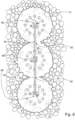
- the intention of the pile wall according to the invention can be achieved by a pile wall, which includes several parallel concrete piles connected together on a stable ground layer, which concrete piles includes reinforcement set inside at least one concrete pile, and the concrete piles an essentially circular cross-sectional shape, and in which the concrete piles form the pile wall's outer surface, and each of which concrete pile has an outer surface.
- Each concrete pile connects by a fully integrated concrete structure to each adjacent concrete pile by a sector of 1° - 50°, preferably 5° - 15°, of the concrete pile's cross-section.
- the concrete structure has a contact surface formed on the outer surface of both sides of the pile wall directly to a stable ground layer, and the contact surface is integrated with the stable ground layer.
- connection surface area of the adjacent concrete piles to each other is considerably smaller than in pile walls of the prior art and, thanks to the pipe piles utilizing interlocks, is always the same, i.e. constant. Thanks to the small connection surface area, the concrete piles' effective dimension is the pile wall is large and the pile wall can be formed with less drilling than pile walls of the prior art. Thanks to the contact surface in direct contact with the ground the pile wall need not necessarily extend to the bedrock, as the contact surface locks the pile wall to the surrounding ground, thus preventing it from slipping down.
- integrated concrete structure refers to the concrete of the adjacent concrete piles joining to form a unified concrete structure.
- the term integration of the contact surface with the stable layer refers to the fact that, when it hardens the concrete adheres directly to the stable ground layer, locking the pile wall in place in such a way that the pile wall cannot slip down, unlike a slippery pile wall formed of pipe piles.
- the pile wall according to the invention is formed preferably only of adjacent concrete piles and reinforcement fitted inside at least one concrete pile.
- the metal pipe piles do not remain in the pile wall.
- the concrete piles of the said pile wall are in direct contact with the ground.
- the concrete piles of the said pile wall are in direct contact with the ground.
- the stable ground layer advantageously forms the formwork of the pile wall.
- the pile wall is preferably watertight. This is achieved by vibrating the lifted pipe piles, which compact the concrete to become watertight.
- the concrete piles of the pile wall preferably extend only to the upper surface of the rock that forms a stable layer and the pile wall includes, in addition, a reserve pipe fitted inside a reinforcement, a locking hole drilled into the rock through the reserve pipe, and a rock bolt fitted through the reserve pipe, to lock the concrete piles to the rock horizontally.
- the pipe piles need not be drilled into the rock, but only to the surface of the rock, after which each concrete pile is attached to the rock with the aid of the rock bolt.
- the concrete piles of the pile wall are in a single row.
- the length of the pile wall can be maximized with a minimum number of concrete piles. This is possible due to the use of interlocking pipe piles, because then the concrete piles can be formed with sufficient precision at the correct distance from each other to form a unified and durable pile wall.
- the pipe piles' interlocks include male interlocks expanding from the main shape of the pipe pile and female interlocks attached to the male interlocks by welding.
- the male interlocks are part of the pipe pile's internal volume.
- the width of the male interlock can 20 - 30 % of the diameter of the pipe pile.
- the concrete piles' diameter can be 200 - 2000 mm, preferably 600 - 1200 mm. With such a diameter a sufficient number of reinforcements can be fitted to the concrete pile for the pile wall to become sufficiently strong against the forces acting on it.
- the pile wall's height can be 1 - 50 m, preferably 5 - 30 m, 20 - 30 m, depending on the drilling equipment used.
- the pile wall includes as reinforcement vertical reinforcements and slanting reinforcements, which are arranged at an angle of 45 - 70° to the pipe piles' longitudinal direction in the longitudinal direction of the pile wall before concrete casting, which slanting reinforcements settle partly on the webs between the pile wall's pipe piles as a result of the pressure caused by the concrete casting.
- a reinforced pile wall is obtained in the case of the pile wall between the concrete piles.
- the pile wall includes as reinforcement vertical reinforcements and transverse reinforcements which bind the vertical reinforcements in the various concrete piles to each other to reinforce the pile wall. With the aid of the transverse reinforcements a strong pile wall is created, even if the pipe piles are removed completely.
- the transverse reinforcements are spring reinforcements attached to the vertical reinforcements, which are arranged to compress on the inside of the pipe pile and the expand essentially in the transverse direction of the pipe piles and in the longitudinal direction of the pile wall, to reinforce the pile wall when the pipe piles are lifted.
- the spring reinforcements can be installed already when installing the other reinforcements, so that their installation does not demand a separate work stage after concrete casting.
- the transverse reinforcements are reinforcements to be spread with the aid of vibration, which are installed inside the pipe pile before concrete casting.
- Such transverse reinforcements need not be welded onto the vertical reinforcements, nor does their placing in the operating position demand a separate stage, if the pipe pile is raised with the aid of vibration.
- the transverse reinforcements are reinforcements embedded in the cast concrete by vibration.
- the concrete of the concrete piles can be ordinary concrete, which is reinforced with various reinforcements, but alternatively it can also be macro- or steel fibre concrete, in which macro- or steel fibres form at least part of the reinforcements.
- Macro-fibre concrete refers to concrete, in which there are evenly distributed plastic fibres, the length of which can be, for example, 10 - 50 mm, depending on the type of fibre.
- Steel-fibre concrete refers to concrete in which there are evenly distributed steel-wire lengths, which can be, for example, 25 - 60 mm in length and 0.4 - 1.05 mm in diameter.
- the pipe pile has a round cross-section in both the method according to the invention and the pile wall, when a hollow volume forms inside it for concrete and reinforcements.
- the pipe pile acts as temporary formwork in the method according to the invention for forming a pile wall according to the invention.
- the pile wall includes a transverse support beam joined to the outer surfaces of the concrete piles on the side to be constructed of the exposed pile wall.
- the pile wall can include anchors for anchoring the pile wall to a stable ground layer on the opposite side of the pile wall to the transverse support beam.
- Preferred applications of the method and pile wall according to the invention are abutment-wall structures, building foundations, car-park buildings, harbour piers, road and railway structures, bridges, and cut-out walls for separating contaminated soil.
- the erection of the pile wall 10 starts by drilling pipe piles 16 into the ground 100.
- a drill using a medium for flushing can be used, which can be any device whatever intended for drilling pipe piles, with the aid of which a non-rotating pipe pile can be pulled or pushed.
- the medium is preferably a liquid, with the aid of which drilling waste is flushed along the outside of the pipe pile and out of the drill hole.
- the drilling waste can be flushed with the aid of a liquid or air inside the pipe pile.
- the drilling device is a hammer drill, but it can also be only a rotary drill.
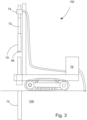
- Figure 3 shows an example of a drilling device 102, which includes the following main parts: bit 70, reamer 56, drill bar 72, rotating device 74, and a pressurized-medium pumping unit 76.
- the drill can be, for example, a drill made by the Finnish company Epiroc Oy.
- the pipe pile should be such that it is able to move the pipe pile in the drill hole without rotating the pipe pile 16, because the pipe pile 16 includes longitudinal interlocks 14 in it, which prevent the rotation of the pipe pile 16.
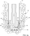
- the pipe pile is pulled after the pilot bit 52, the pipe pile 16 being connected after the rotating pilot bit 52 with the aid of a casing shoe nonrotatingly according to Figure 4 .
- the pipe pile 16 includes according to Figure 4a a transfer shoulder 55, with the aid of which the pipe pile is, depending on the drilling device, either pulled or pushed after the drill into the drill hole.
- the drilling device can also include other means for pressing the pipe pile by its end into the drill hole.
- the drill hole 12 is expanded with the aid of a reamer 56 in addition to the pilot bit, so that the pipe pile 16 equipped with an interlock 14 will fit to come after the pilot bit 52 into the drill hole without damaging the interlock 14 or pushing it against the ground 100, when, for example, the female interlocking member 30 would be filled with soil.
- the reamer 56 can be, for example, a reamer bit or a ring-auger bit.
- the drill hole 12 is drilled preferably so deeply into the ground 100 that the drill hole 12 reaches a so-called stable layer in the ground 100, which remains in place and does not move horizontally.
- the stable layer is shown in Figure 2 with the reference number 60.
- Such as layer can be a non-cohesive soil layer or alternatively rock.
- a sufficient depth, to which the drill hole should preferably extend to the stable layer is at least one metre, preferably 2 - 4 m. In all cases, however, this is not necessary.
- the drill hole is flushed at the same time, to remove drilling waste from the drill hole.
- Flushing is preferably performed with the aid of a liquid along the pipe pile's outer surface and out of the drill hole, but the liquid and drilling waste can also be led inside the pipe pile. Air can also be used as an alternative to liquid in flushing.
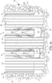
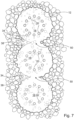
- the interlocks 14 of each pipe pile 16 include, according to Figures 1a - 1e , a long interlocking member 44 and a short interlocking member 46.
- the long interlocking member 44 of the new pipe pile extends farther than the diameter of the reamer from the centre line of the pipe pile 16.
- the long interlocking member 44 is set in such a way that it connects to the short interlocking member of the already drilled pipe pile 16.
- the reamer can expand the drill hole 12 during drilling, so that adjacent drill holes 12 intersect each other at the intersection point 50, thus forming a link between the drill holes 12.
- the long interlocking member 44 travels after the reamer along the adjacent drilled pipe pile's 16 short interlocking member 46 while the reamer does not strike either interlocking member of the interlock 14.
- the first pipe pile can have a different structure, in that there can be only two short interlocking members, as there are no adjacent drill holes, and the interlock thus cannot extend farther from the pipe pile's centre line than the drilling device's reamer. Alternatively, there can be only one short interlock in the first pipe pile.
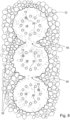
- the pipe piles' 16 interlocks 14 can be according to Figures 13a and 13b , in which the interlocks 14 include male interlocks 86 and female interlocks 88 welded to the male interlocks.
- the female interlock 88 can be attached to the pipe pile's 16 outer surface's male interlock 86 by welding 90.
- the advantage of such a pipe pile is the bulge in the interior of the pipe pile 16 formed by the male interlocks 86, so that the cast concrete is quite wide also on the webs 35 between the main shape of the pipe pile. This leads to a sturdier pile wall.
- the adjacent drill holes 12 can also be drilled in such a way that a thin soil layer remains between them, which is arranged to be broken by the pipe pile's 16 interlock 14 (not shown) .
- the largest dimension of the ground layer depends on the ground's properties. In soft soil the interlock 14 can penetrate through even a wide ground layer and nevertheless bind the adjacent pipe piles to each other. The interlock can then too be channelled, for example, for steel reinforcement or for injection.
- the web 35 remaining between the main shapes of the pipe piles can even be in the order of the pipe's diameter D, i.e. the web's dimension would be 0 - D, however preferably 0 - D/2. Naturally, the dimension can be limited by the fact that the concrete cast into each pipe pile should join the concrete mass of the adjacent pipe pile when the pipe piles are raised.
- the pipe piles 16 can include brackets 26, which support the pipe pile 16 against the inner surface of the drill hole 12 and thus prevent the pipe pile turning in the direction of the adjacent drill hole 12.
- the brackets 26 can be of such a height that they extend slightly farther radially than the reamer from the centre line of the pipe pile. If the reamer makes, for example a drill hole 54-mm larger than the diameter of the pipe pile at the brackets, the diameter can be up to 56 - 58-mm larger than the pipe pile's diameter.
- the brackets then travel against the ground and wear slightly, settling securely against the ground.
- the brackets 26 can have a side profile like a shark's fin according to Figure 4 , when they travel smoothly in the drill hole after the drilling device. It should be understood that differing from 1b - 1d the brackets may also be blunt, with, for example, a semi-circularly shaped side profile, or otherwise be suitably shaped for the purpose.
- the reinforcements 20 can be placed inside the pipe piles 16, according to Figures 1c and 4c . If resources permit, the placing of the reinforcements 20 can be started in some of the pipe piles 16 simultaneously with the drilling of the other pipe piles 16 into the ground 100 according to Figure 4b . In reinforcement, ribbed bar, or some other similar reinforcing steel, is lowered inside the pipe pile 16.
- the reinforcement is preferably of a flat ribbed-steel mesh welded into a circular structure. The amount of reinforcement is determined by the strength required in the pile wall 10, which in turn depends on the demands of the operating environment.
- concrete 18 is cast inside the pipe piles 16 according to Figure 1d , inside which the reinforcements 20 remain.
- the pipe pile 16 acts as formwork for the concrete 18.
- the concrete 18 fills the interior of the pipe pile 16, thus forming a reinforced concrete pile 22.
- a selected binder can be mixed with the concrete 18 to improve the water-tightness of the concrete 18.
- the concrete can be cast into the pipe piles already before the installation of the reinforcements, but then the reinforcements must be vibrated to press through the freshly cast concrete.
- the reinforcements 20 can also include transverse reinforcements 19 creating a slanting support.
- the transverse reinforcements are preferably spring reinforcements 92, which can be welded onto the vertical reinforcements 21.
- the spring reinforcements are an embodiment of the transverse reinforcements.
- the spring reinforcements 92 can include a weld part 91 and a transverse-support part 93 transverse to the concrete piles in the final pile wall, and a joint between them.
- the spring reinforcements 92 are torsion springs, in which the weld part 91 is welded onto the vertical reinforcements 21 and the transverse-support part 93 tensions when the reinforcements are installed inside the pipe pile 16, being released finally during the lifting of the pipe pile 16 to become transverse to the pipe piles 16, thus forming reinforcements also in the area of the pipe piles' 16 interlocks in the area between the concrete piles 22.
- the spring reinforcement 92 can also be a straight spring 95 according to Figures 14a - 14b , which can be attached to a corral 96 surrounding the vertical reinforcements 21.
- the vertical reinforcements too 21 are bound together with the aid of an installation band 94.
- pipe piles can be drilled into the ground together in an essentially unbroken casting sequence, until the lifting of the pipe piles is commenced.
- the pipe piles are lifted before the concrete binds, in which the concrete paste changes from fluid to rigid, after which the concrete begins to harden and the lifting of a pipe pile becomes very difficult or even impossible, without breaking the structure of the concrete pile.
- the length of the casting sequence can be influenced by using retardants in the concrete mix, which slow the binding of the concrete and thus lengthen the time for lifting the pipe piles.
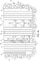
- the pipe piles 16 can be begun to be lifted one at a time partly or completely out of the drill holes 12, before the concrete 18 bonds inside the pipe piles, changing from a fluid, workable concrete mass into a rigid one, according to Figures 4c and 4d .
- the pipe pile 16 is attached at its upper end to a lifting device, which lifts the pipe pile 16 out slowly, while preferably vibrating the pipe pile 16.
- a lifting device the vibrating lifting device made by the German manufacturer ABI GmbH under the product name MRZV-VV, or Liebherr's LRB255 lifting device can be used.
- the lifting device grips the end of the pipe pile and lifts it upwards out of the drill hole while vibrating it.
- the vibration of the pipe pile 16 also vibrates and compacts the concrete 18 inside the pipe pile 16.
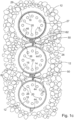
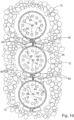
- the still fluid concrete between the concrete 18 and the drill hole 12 spreads laterally by gravity, filling the drill hole 12 and forming a concrete pile 22 and spreading between the drill holes 12 connected to each other to form a unified pile wall 10.
- the vibration of the pipe pile 16 compacts the still fluid concrete 18 in the drill hole 12 against the ground 100.
- the outer surface 23 of the concrete pile 22 forms a contact surface 25 against the ground 100, which is shown in Figures 1e and 2 .
- the pipe piles can also be raised without vibration, but the use of vibration is the preferred manner of implementation, as it compacts the concrete at the same time.
- the pile wall 10 can also include transverse reinforcements 19 to be vibrated after the concrete casting and the lifting of the pipe piles, which are preferably arranged between the vertical reinforcements, in such a way that the vertical reinforcements 21 act as guides when installing the transverse reinforcements 19.
- a preferably cast transverse support beam 71 can also be formed on the exposed pile wall 10 in connection with the pile wall, on the construction 73 side of the pile wall 10.
- the construction 73 side of the pile wall 10 refers to the side on which the building or similar is created, the opposite side of the pile wall 10 being, in turn, the stable side 75.
- the pile wall 10 can also be anchored in the stable layer 60 of the ground 100 on the opposite side of the pile wall 10 relative to the support beam 71, with the aid of anchors 77. The anchor 77 then penetrates both the support beam 71 and the pile wall's 10 concrete pile 22 and further extends to the ground's 100 stable layer 60, thus locking the pile wall 10 in place even more firmly.
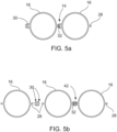
- various interlocks 14 can be used when drilling the pipe piles to connect the pipe piles 16.
- a male interlocking member 28 there is both a male interlocking member 28 and a female interlocking member 30 in each pipe pile.
- a female interlocking member 30 there are, in turn, pipe piles 16, in which there are only male interlocking members 28 and the pipe piles 16 are connected with the aid of an intermediate interlocking member 42.
- the intermediate interlocking member 42 includes two female interlocking members 30.
- concrete injection can be used during the lifting of the pipe piles, according to a first embodiment in the method. Concrete can be injected through a female interlocking member as the pipe pile is being lifted. The pile wall then receives additional concrete in the area between the concrete piles, which reinforces the structure and improves its tightness.
- an injection pipe can be temporarily locked to the pipe pile by a locking means, which is released from the pipe pile when concrete is cast into the pipe pile or when the pipe pile is lifted, and remains in the bottom of the drill hole from the weight of the concrete.
- the injection pipe 34 is shown in Figure 7 and can be located, according to Figure 7 , either inside the concrete 18 of the concrete pile 22, or outside the concrete pile 18.
- the injection hose 34 can be split over its length, except for the ends, when during injection the concrete is able to fill possible cavities remaining in the concrete piles.
- the injection hose's diameter can be, for example, 15 - 25 mm.
- the locking means can be, for example, a metal sheet welded lightly to the side of the pipe pile, which presses the injection hose against the pipe pile while the pipe pile is drilled and detaches by the concrete's weight or when the pipe pile is lifted, pressing the injection hose under it in the drill hole. After the pipe pile is lifted, additional concrete or sealant can still be injected into the drill hole, which ensures the water-tightness of the pile wall.
- the injection pipe can be, for example, a steel reserve pipe.
- Figure 6 shows a third embodiment, in which the durability and water-tightness of the pile wall 10 is improved with the aid of a separate support plate 40.
- the support plate 40 there are inside the pipe piles, for example, H beams or other similar guide supports 48 placed inside the pipe piles in connection with reinforcement, which remain inside the concrete cast in the pipe pile.
- the support plate 40 connecting the concrete piles 22 can be driven between the H beams 48, when the H beams or similar supports guide the support plate's 40 impacts inside the concrete pile 22.
- the support plates act as transverse reinforcements in the pile wall.
- brackets described in the present application can also be used generally as part of the drilled pipe piles in connection with the construction of pile walls, and their use is not restricted only to the method according to the invention.
- the brackets can thus be part of the pipe pile, which are joined to the pipe pile's outer surface at the end of the pipe pile next to the drilling device's ring bit and at the brackets the pipe pile's diameter is 1 - 4 mm larger than the drill hole being drilled.
- the brackets stabilize the pipe pile being placed, particularly in its rock-drilled portion, so that lateral loads, acting in the direction of the previously drilled pipe pile, are larger for the placed pipe pile.
- At least one plough protrusion 82 is welded next to the interlock 14 at the end 84 of the pipe pile 16 entering the drill hole 12 first, before the pipe pile 16 is drilled into the ground 100, which plough protrusion 82 is a continuous distance of a sector on the pipe pile's 16 outer circumference and protrudes from the pipe pile 16 by at most by the same amount as the reamer used in the drilling device 102.
- the plough protrusion 82 is intended to displace ground 100 when lifting the pipe pile 16 to make the joining of the concrete piles 22 more effective.
- the plough protrusion thus 'ploughs' the ground 100 from in front to the side, thus enlarging the connection between two adjacent drill holes 12, which can, in some cases be only the width of the interlock, and permit the concrete to effectively spread from one drill hole 12 to another, effectively joining the adjacent concrete piles 22 to each other.
- the plough protrusion 82 can form a vacuum behind itself, as the concrete surrounds and fills the space left in the pipe pile's drill hole as the pipe pile is raised and vibrated. The vacuum in turn sucks concrete effectively between the drill holes, thus joining the concrete piles.
- the plough protrusions 82 are plates welded to the pipe pile 16, which are at an angle of, for example, 30 - 60°, preferably 40 - 50° to the longitudinal direction of the pipe pile 16.
- the plough protrusion can also be a casing structure transversely to the pipe pile, or some other protrusion that displaces ground from in front when raising the pipe pile.
- the plough protrusion can be formed in a sector of the pipe pile of a minimum of 1°, preferably 5° of the pipe pile's perimeter and a sector of a maximum of 50°, preferably 15°.
- Figure 8 shows an embodiment of the method according to the invention, in which the reinforcements 20 preferably include at least one hollow reinforcement in each pipe pile 16, inside which a reserve pipe 72 is fitted.
- the reserve pipe 72 is protected during the casting of concrete in the pipe pile 16, so that the reserve pipe 72 remains empty.
- compaction mass or concrete can be fed through the reserve pipe, to ensure the pile wall's tightness.
- the pipe piles can be drilled only down to the rock surface, when a locking holes can be drilled into the rock through the reserve pipe, through which the concrete pile can be locked to the reinforcement by a rock bolt to the locking hole and through it to the rock.
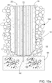
- FIG 9 shows one form of implementation of the method according to the invention, in which separate channels 80 are formed in the outer surfaces of the pipe piles 16, through which liquid lubricant can be fed into the drill hole 12 outside the pipe piles 16.
- the liquid lubricant remaining between the drill hole 12 and the pipe pile 16 facilitates the lifting of the pipe piles by reducing the friction between the pipe piles and the drill hole.
- the liquid lubricant can also be fed, for example, through the female interlocking members of the pipe piles' interlocking members, or using a separate channel formed in connection with the interlocking members.
- a separate material layer 29, which is arranged to reduce the friction between the concrete and the pipe pile, on the inner surface 27 of the pipe pile can, according to Figure 1c be used.
- the material layer 29 can be, for example, of Teflon.
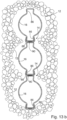
- the pile wall in the case of the pipe piles, can be drilled down to the upper surface of the rock 65 forming the stable layer 60.
- the reinforcement 20 includes a hollow reserve pipe 72, which is left empty when casting the concrete, and through which a locking hole 62 can be drilled into the rock, according to Figure 10a .
- the pile wall is locked by setting a rock bolt 64 in the locking hole 62 through the reserve pipe 72, which holds the concrete piles 22 horizontally in place in the rock 65.
- the pile wall can also be formed in such a way that the pipe pile 16 between the upper and lower pipe piles 16 in the line is drilled to the side of the line, on that side of the line in which the soil pressure acting on the pile wall is greater.
- This single offset pipe pile 16 can have a smaller diameter than the other pipe piles.
- the offset pipe pile can be otherwise the same in structure as the other pipe piles and the interlocks of the pipe piles joined to it should be compatibly located in the circle of pipe piles, relative to each other.
Landscapes
- Engineering & Computer Science (AREA)
- Structural Engineering (AREA)
- Mining & Mineral Resources (AREA)
- Life Sciences & Earth Sciences (AREA)
- General Life Sciences & Earth Sciences (AREA)
- Paleontology (AREA)
- Civil Engineering (AREA)
- General Engineering & Computer Science (AREA)
- Piles And Underground Anchors (AREA)
Applications Claiming Priority (7)
| Application Number | Priority Date | Filing Date | Title |
|---|---|---|---|
| FI20196036 | 2019-11-29 | ||
| FI20196069A FI20196069A1 (fi) | 2019-11-29 | 2019-12-10 | Menetelmä porattavan seinärakenteen muodostamiseksi maaperään ja vastaava porattava seinärakenne |
| FI20196103 | 2019-12-19 | ||
| FI20196133 | 2019-12-27 | ||
| FI20205010 | 2020-01-03 | ||
| FI20205225 | 2020-03-04 | ||
| PCT/FI2020/050803 WO2021105569A1 (en) | 2019-11-29 | 2020-11-27 | Method for forming a pile wall in ground and a corresponding pile wall |
Publications (3)
| Publication Number | Publication Date |
|---|---|
| EP4065776A1 EP4065776A1 (en) | 2022-10-05 |
| EP4065776C0 EP4065776C0 (en) | 2023-12-20 |
| EP4065776B1 true EP4065776B1 (en) | 2023-12-20 |
Family
ID=74141586
Family Applications (1)
| Application Number | Title | Priority Date | Filing Date |
|---|---|---|---|
| EP20838588.0A Active EP4065776B1 (en) | 2019-11-29 | 2020-11-27 | Method for forming a pile wall in ground and a corresponding pile wall |
Country Status (3)
| Country | Link |
|---|---|
| EP (1) | EP4065776B1 (pl) |
| PL (1) | PL4065776T3 (pl) |
| WO (1) | WO2021105569A1 (pl) |
Families Citing this family (5)
| Publication number | Priority date | Publication date | Assignee | Title |
|---|---|---|---|---|
| WO2022200692A1 (en) * | 2021-03-25 | 2022-09-29 | Pirkan Laatupalvelu Oy | Method for forming a wall structure in the ground by drilling and wall structure formed by drilling |
| US12065799B2 (en) | 2019-11-29 | 2024-08-20 | Pirkan Laatupalelu Oy | Method for forming a pile wall in ground and a corresponding pile wall |
| US20250122687A1 (en) * | 2022-01-24 | 2025-04-17 | Thanh Minh Vo | Pile foundation-substructure column system and construction method of the pile foundation-substructure column system |
| CN115288112B (zh) * | 2022-08-17 | 2024-02-23 | 北京市市政一建设工程有限责任公司 | 一种河道软土地基加固结构 |
| CN116005664A (zh) * | 2022-12-23 | 2023-04-25 | 中铁二院工程集团有限责任公司 | 用于钻孔桩基础的施工方法、组合钢护筒及钻孔桩基础 |
Family Cites Families (6)
| Publication number | Priority date | Publication date | Assignee | Title |
|---|---|---|---|---|
| NO119728B (pl) * | 1965-09-13 | 1970-06-22 | Sven Erik Bjerking | |
| GB2315086A (en) * | 1996-07-10 | 1998-01-21 | Kwong Yee Chan | Piling |
| KR100866162B1 (ko) * | 2008-08-14 | 2008-10-30 | 이재호 | 의자형 자립식 흙막이벽의 시공방법 |
| WO2010032485A1 (ja) * | 2008-09-18 | 2010-03-25 | 新日本製鐵株式会社 | 鋼管矢板、鋼管矢板の継手構造、及び壁構造並びに鋼管矢板の引き抜き方法 |
| KR101190739B1 (ko) * | 2010-06-14 | 2012-10-12 | 공정호 | 지하 합성 외벽 구조물 시공 방법 및 이에 의해 시공된 지하 합성 외벽 구조물 |
| KR101846455B1 (ko) * | 2017-07-11 | 2018-04-06 | 송호산업 주식회사 | 겹침형 주열식 벽체의 시공방법 및 이에 의해 시공된 주열식 벽체 |
-
2020
- 2020-11-27 WO PCT/FI2020/050803 patent/WO2021105569A1/en not_active Ceased
- 2020-11-27 PL PL20838588.0T patent/PL4065776T3/pl unknown
- 2020-11-27 EP EP20838588.0A patent/EP4065776B1/en active Active
Also Published As
| Publication number | Publication date |
|---|---|
| PL4065776T3 (pl) | 2024-05-20 |
| WO2021105569A1 (en) | 2021-06-03 |
| EP4065776C0 (en) | 2023-12-20 |
| EP4065776A1 (en) | 2022-10-05 |
Similar Documents
| Publication | Publication Date | Title |
|---|---|---|
| EP4065776B1 (en) | Method for forming a pile wall in ground and a corresponding pile wall | |
| KR100866162B1 (ko) | 의자형 자립식 흙막이벽의 시공방법 | |
| CN103958780B (zh) | 形成胶结挡土墙的方法 | |
| US9567723B2 (en) | Open-end extensible shells and related methods for constructing a support pier | |
| WO2006057545A1 (en) | Tunnelling method using pre-support concept and an adjustable apparatus thereof | |
| CN110130363A (zh) | 装配式植入基坑围护桩与桩墙合一结构及其施工方法 | |
| KR102113291B1 (ko) | Phc 파일을 이용한 벽체 조성방법 및 벽체 | |
| WO2022200692A1 (en) | Method for forming a wall structure in the ground by drilling and wall structure formed by drilling | |
| KR101081343B1 (ko) | 콤팩션 그라우팅 공법 | |
| KR101341260B1 (ko) | 기존 콘크리트 기초 구조물의 보강 공법 | |
| US20240368853A1 (en) | Method for forming a pile wall in ground and a corresponding pile wall | |
| KR20210020573A (ko) | 주열 보강된 2열 흙막이 자립 합성벽의 시공방법 | |
| KR100762991B1 (ko) | 고강도 몰탈을 충진하는 기성말뚝 매입공법 | |
| KR100781492B1 (ko) | 옹벽구조 및 그 시공방법 | |
| AU2022339936B2 (en) | A system and method for installing an aggregate pier | |
| KR20190109890A (ko) | 차수 성능을 향상시키기 위한 흙막이 벽체용 합성 phc 파일 | |
| KR102793163B1 (ko) | 지반보강 및 지지력을 향상시키는 고강도 phc 파일의 스마트 지반보강 공법 | |
| KR100493516B1 (ko) | 현장 마이크로 파일과 조립식 브라켓을 이용한 교각용조립식 기초보강 구조체 및 그의 구축방법 | |
| KR101021913B1 (ko) | 흙막이 공사용 차수 가시설 시공방법 | |
| KR100327547B1 (ko) | 가설흙막이벽을영구구조물로활용하는지하옹벽구축방법 | |
| KR102070912B1 (ko) | 흙막이 벽체용 phc 파일, 이를 제조하기 위한 몰드 조립체 및 이를 이용한 제조방법 | |
| EP4314415A1 (en) | Method for forming a wall structure in the ground by drilling and wall structure formed by drilling | |
| US10077539B1 (en) | Wall and retaining members and fluidizing installation of retaining members | |
| FI20196069A1 (fi) | Menetelmä porattavan seinärakenteen muodostamiseksi maaperään ja vastaava porattava seinärakenne | |
| KR200373276Y1 (ko) | 강관파일의 지지력 확장구조 |
Legal Events
| Date | Code | Title | Description |
|---|---|---|---|
| STAA | Information on the status of an ep patent application or granted ep patent |
Free format text: STATUS: UNKNOWN |
|
| STAA | Information on the status of an ep patent application or granted ep patent |
Free format text: STATUS: THE INTERNATIONAL PUBLICATION HAS BEEN MADE |
|
| PUAI | Public reference made under article 153(3) epc to a published international application that has entered the european phase |
Free format text: ORIGINAL CODE: 0009012 |
|
| STAA | Information on the status of an ep patent application or granted ep patent |
Free format text: STATUS: REQUEST FOR EXAMINATION WAS MADE |
|
| 17P | Request for examination filed |
Effective date: 20220623 |
|
| AK | Designated contracting states |
Kind code of ref document: A1 Designated state(s): AL AT BE BG CH CY CZ DE DK EE ES FI FR GB GR HR HU IE IS IT LI LT LU LV MC MK MT NL NO PL PT RO RS SE SI SK SM TR |
|
| DAV | Request for validation of the european patent (deleted) | ||
| DAX | Request for extension of the european patent (deleted) | ||
| GRAP | Despatch of communication of intention to grant a patent |
Free format text: ORIGINAL CODE: EPIDOSNIGR1 |
|
| STAA | Information on the status of an ep patent application or granted ep patent |
Free format text: STATUS: GRANT OF PATENT IS INTENDED |
|
| INTG | Intention to grant announced |
Effective date: 20230718 |
|
| GRAS | Grant fee paid |
Free format text: ORIGINAL CODE: EPIDOSNIGR3 |
|
| GRAA | (expected) grant |
Free format text: ORIGINAL CODE: 0009210 |
|
| STAA | Information on the status of an ep patent application or granted ep patent |
Free format text: STATUS: THE PATENT HAS BEEN GRANTED |
|
| AK | Designated contracting states |
Kind code of ref document: B1 Designated state(s): AL AT BE BG CH CY CZ DE DK EE ES FI FR GB GR HR HU IE IS IT LI LT LU LV MC MK MT NL NO PL PT RO RS SE SI SK SM TR |
|
| REG | Reference to a national code |
Ref country code: GB Ref legal event code: FG4D |
|
| REG | Reference to a national code |
Ref country code: CH Ref legal event code: EP |
|
| REG | Reference to a national code |
Ref country code: DE Ref legal event code: R096 Ref document number: 602020023193 Country of ref document: DE |
|
| REG | Reference to a national code |
Ref country code: IE Ref legal event code: FG4D |
|
| U01 | Request for unitary effect filed |
Effective date: 20240116 |
|
| U07 | Unitary effect registered |
Designated state(s): AT BE BG DE DK EE FI FR IT LT LU LV MT NL PT SE SI Effective date: 20240125 |
|
| PG25 | Lapsed in a contracting state [announced via postgrant information from national office to epo] |
Ref country code: GR Free format text: LAPSE BECAUSE OF FAILURE TO SUBMIT A TRANSLATION OF THE DESCRIPTION OR TO PAY THE FEE WITHIN THE PRESCRIBED TIME-LIMIT Effective date: 20240321 |
|
| PG25 | Lapsed in a contracting state [announced via postgrant information from national office to epo] |
Ref country code: ES Free format text: LAPSE BECAUSE OF FAILURE TO SUBMIT A TRANSLATION OF THE DESCRIPTION OR TO PAY THE FEE WITHIN THE PRESCRIBED TIME-LIMIT Effective date: 20231220 |
|
| PG25 | Lapsed in a contracting state [announced via postgrant information from national office to epo] |
Ref country code: GR Free format text: LAPSE BECAUSE OF FAILURE TO SUBMIT A TRANSLATION OF THE DESCRIPTION OR TO PAY THE FEE WITHIN THE PRESCRIBED TIME-LIMIT Effective date: 20240321 Ref country code: ES Free format text: LAPSE BECAUSE OF FAILURE TO SUBMIT A TRANSLATION OF THE DESCRIPTION OR TO PAY THE FEE WITHIN THE PRESCRIBED TIME-LIMIT Effective date: 20231220 |
|
| PG25 | Lapsed in a contracting state [announced via postgrant information from national office to epo] |
Ref country code: RS Free format text: LAPSE BECAUSE OF FAILURE TO SUBMIT A TRANSLATION OF THE DESCRIPTION OR TO PAY THE FEE WITHIN THE PRESCRIBED TIME-LIMIT Effective date: 20231220 Ref country code: NO Free format text: LAPSE BECAUSE OF FAILURE TO SUBMIT A TRANSLATION OF THE DESCRIPTION OR TO PAY THE FEE WITHIN THE PRESCRIBED TIME-LIMIT Effective date: 20240320 Ref country code: HR Free format text: LAPSE BECAUSE OF FAILURE TO SUBMIT A TRANSLATION OF THE DESCRIPTION OR TO PAY THE FEE WITHIN THE PRESCRIBED TIME-LIMIT Effective date: 20231220 |
|
| PG25 | Lapsed in a contracting state [announced via postgrant information from national office to epo] |
Ref country code: IS Free format text: LAPSE BECAUSE OF FAILURE TO SUBMIT A TRANSLATION OF THE DESCRIPTION OR TO PAY THE FEE WITHIN THE PRESCRIBED TIME-LIMIT Effective date: 20240420 |
|
| PG25 | Lapsed in a contracting state [announced via postgrant information from national office to epo] |
Ref country code: CZ Free format text: LAPSE BECAUSE OF FAILURE TO SUBMIT A TRANSLATION OF THE DESCRIPTION OR TO PAY THE FEE WITHIN THE PRESCRIBED TIME-LIMIT Effective date: 20231220 |
|
| PG25 | Lapsed in a contracting state [announced via postgrant information from national office to epo] |
Ref country code: SK Free format text: LAPSE BECAUSE OF FAILURE TO SUBMIT A TRANSLATION OF THE DESCRIPTION OR TO PAY THE FEE WITHIN THE PRESCRIBED TIME-LIMIT Effective date: 20231220 |
|
| PG25 | Lapsed in a contracting state [announced via postgrant information from national office to epo] |
Ref country code: SM Free format text: LAPSE BECAUSE OF FAILURE TO SUBMIT A TRANSLATION OF THE DESCRIPTION OR TO PAY THE FEE WITHIN THE PRESCRIBED TIME-LIMIT Effective date: 20231220 Ref country code: SK Free format text: LAPSE BECAUSE OF FAILURE TO SUBMIT A TRANSLATION OF THE DESCRIPTION OR TO PAY THE FEE WITHIN THE PRESCRIBED TIME-LIMIT Effective date: 20231220 Ref country code: RO Free format text: LAPSE BECAUSE OF FAILURE TO SUBMIT A TRANSLATION OF THE DESCRIPTION OR TO PAY THE FEE WITHIN THE PRESCRIBED TIME-LIMIT Effective date: 20231220 Ref country code: IS Free format text: LAPSE BECAUSE OF FAILURE TO SUBMIT A TRANSLATION OF THE DESCRIPTION OR TO PAY THE FEE WITHIN THE PRESCRIBED TIME-LIMIT Effective date: 20240420 Ref country code: CZ Free format text: LAPSE BECAUSE OF FAILURE TO SUBMIT A TRANSLATION OF THE DESCRIPTION OR TO PAY THE FEE WITHIN THE PRESCRIBED TIME-LIMIT Effective date: 20231220 |
|
| REG | Reference to a national code |
Ref country code: DE Ref legal event code: R097 Ref document number: 602020023193 Country of ref document: DE |
|
| PLBE | No opposition filed within time limit |
Free format text: ORIGINAL CODE: 0009261 |
|
| STAA | Information on the status of an ep patent application or granted ep patent |
Free format text: STATUS: NO OPPOSITION FILED WITHIN TIME LIMIT |
|
| 26N | No opposition filed |
Effective date: 20240923 |
|
| U20 | Renewal fee for the european patent with unitary effect paid |
Year of fee payment: 5 Effective date: 20241125 |
|
| PG25 | Lapsed in a contracting state [announced via postgrant information from national office to epo] |
Ref country code: MC Free format text: LAPSE BECAUSE OF FAILURE TO SUBMIT A TRANSLATION OF THE DESCRIPTION OR TO PAY THE FEE WITHIN THE PRESCRIBED TIME-LIMIT Effective date: 20231220 |
|
| PG25 | Lapsed in a contracting state [announced via postgrant information from national office to epo] |
Ref country code: IE Free format text: LAPSE BECAUSE OF NON-PAYMENT OF DUE FEES Effective date: 20241127 |
|
| REG | Reference to a national code |
Ref country code: CH Ref legal event code: U11 Free format text: ST27 STATUS EVENT CODE: U-0-0-U10-U11 (AS PROVIDED BY THE NATIONAL OFFICE) Effective date: 20251201 |
|
| U20 | Renewal fee for the european patent with unitary effect paid |
Year of fee payment: 6 Effective date: 20251124 |
|
| PGFP | Annual fee paid to national office [announced via postgrant information from national office to epo] |
Ref country code: GB Payment date: 20251121 Year of fee payment: 6 |
|
| PGFP | Annual fee paid to national office [announced via postgrant information from national office to epo] |
Ref country code: CH Payment date: 20251201 Year of fee payment: 6 |
|
| PGFP | Annual fee paid to national office [announced via postgrant information from national office to epo] |
Ref country code: PL Payment date: 20251022 Year of fee payment: 6 |
|
| PG25 | Lapsed in a contracting state [announced via postgrant information from national office to epo] |
Ref country code: HU Free format text: LAPSE BECAUSE OF FAILURE TO SUBMIT A TRANSLATION OF THE DESCRIPTION OR TO PAY THE FEE WITHIN THE PRESCRIBED TIME-LIMIT; INVALID AB INITIO Effective date: 20201127 |