EP4065502B1 - Main girder of bridge crane - Google Patents
Main girder of bridge crane Download PDFInfo
- Publication number
- EP4065502B1 EP4065502B1 EP20892947.1A EP20892947A EP4065502B1 EP 4065502 B1 EP4065502 B1 EP 4065502B1 EP 20892947 A EP20892947 A EP 20892947A EP 4065502 B1 EP4065502 B1 EP 4065502B1
- Authority
- EP
- European Patent Office
- Prior art keywords
- main girder
- plate
- girder
- knife plate
- central web
- Prior art date
- Legal status (The legal status is an assumption and is not a legal conclusion. Google has not performed a legal analysis and makes no representation as to the accuracy of the status listed.)
- Active
Links
Images
Classifications
-
- B—PERFORMING OPERATIONS; TRANSPORTING
- B66—HOISTING; LIFTING; HAULING
- B66C—CRANES; LOAD-ENGAGING ELEMENTS OR DEVICES FOR CRANES, CAPSTANS, WINCHES, OR TACKLES
- B66C17/00—Overhead travelling cranes comprising one or more substantially horizontal girders the ends of which are directly supported by wheels or rollers running on tracks carried by spaced supports
-
- B—PERFORMING OPERATIONS; TRANSPORTING
- B66—HOISTING; LIFTING; HAULING
- B66C—CRANES; LOAD-ENGAGING ELEMENTS OR DEVICES FOR CRANES, CAPSTANS, WINCHES, OR TACKLES
- B66C19/00—Cranes comprising trolleys or crabs running on fixed or movable bridges or gantries
-
- B—PERFORMING OPERATIONS; TRANSPORTING
- B66—HOISTING; LIFTING; HAULING
- B66C—CRANES; LOAD-ENGAGING ELEMENTS OR DEVICES FOR CRANES, CAPSTANS, WINCHES, OR TACKLES
- B66C6/00—Girders, or track-supporting structures, specially adapted for cranes
-
- E—FIXED CONSTRUCTIONS
- E01—CONSTRUCTION OF ROADS, RAILWAYS, OR BRIDGES
- E01D—CONSTRUCTION OF BRIDGES, ELEVATED ROADWAYS OR VIADUCTS; ASSEMBLY OF BRIDGES
- E01D1/00—Bridges in general
-
- E—FIXED CONSTRUCTIONS
- E01—CONSTRUCTION OF ROADS, RAILWAYS, OR BRIDGES
- E01D—CONSTRUCTION OF BRIDGES, ELEVATED ROADWAYS OR VIADUCTS; ASSEMBLY OF BRIDGES
- E01D12/00—Bridges characterised by a combination of structures not covered as a whole by a single one of groups E01D2/00 - E01D11/00
-
- E—FIXED CONSTRUCTIONS
- E01—CONSTRUCTION OF ROADS, RAILWAYS, OR BRIDGES
- E01D—CONSTRUCTION OF BRIDGES, ELEVATED ROADWAYS OR VIADUCTS; ASSEMBLY OF BRIDGES
- E01D18/00—Bridges specially adapted for particular applications or functions not provided for elsewhere, e.g. aqueducts, bridges for supporting pipe-lines
-
- E—FIXED CONSTRUCTIONS
- E01—CONSTRUCTION OF ROADS, RAILWAYS, OR BRIDGES
- E01D—CONSTRUCTION OF BRIDGES, ELEVATED ROADWAYS OR VIADUCTS; ASSEMBLY OF BRIDGES
- E01D19/00—Structural or constructional details of bridges
-
- E—FIXED CONSTRUCTIONS
- E01—CONSTRUCTION OF ROADS, RAILWAYS, OR BRIDGES
- E01D—CONSTRUCTION OF BRIDGES, ELEVATED ROADWAYS OR VIADUCTS; ASSEMBLY OF BRIDGES
- E01D2/00—Bridges characterised by the cross-section of their bearing spanning structure
-
- E—FIXED CONSTRUCTIONS
- E04—BUILDING
- E04B—GENERAL BUILDING CONSTRUCTIONS; WALLS, e.g. PARTITIONS; ROOFS; FLOORS; CEILINGS; INSULATION OR OTHER PROTECTION OF BUILDINGS
- E04B1/00—Constructions in general; Structures which are not restricted either to walls, e.g. partitions, or floors or ceilings or roofs
- E04B1/02—Structures consisting primarily of load-supporting, block-shaped, or slab-shaped elements
- E04B1/08—Structures consisting primarily of load-supporting, block-shaped, or slab-shaped elements the elements consisting of metal
-
- E—FIXED CONSTRUCTIONS
- E04—BUILDING
- E04B—GENERAL BUILDING CONSTRUCTIONS; WALLS, e.g. PARTITIONS; ROOFS; FLOORS; CEILINGS; INSULATION OR OTHER PROTECTION OF BUILDINGS
- E04B1/00—Constructions in general; Structures which are not restricted either to walls, e.g. partitions, or floors or ceilings or roofs
- E04B1/18—Structures comprising elongated load-supporting parts, e.g. columns, girders, skeletons
- E04B1/24—Structures comprising elongated load-supporting parts, e.g. columns, girders, skeletons the supporting parts consisting of metal
-
- E—FIXED CONSTRUCTIONS
- E04—BUILDING
- E04B—GENERAL BUILDING CONSTRUCTIONS; WALLS, e.g. PARTITIONS; ROOFS; FLOORS; CEILINGS; INSULATION OR OTHER PROTECTION OF BUILDINGS
- E04B1/00—Constructions in general; Structures which are not restricted either to walls, e.g. partitions, or floors or ceilings or roofs
- E04B1/342—Structures covering a large free area, whether open-sided or not, e.g. hangars, halls
-
- E—FIXED CONSTRUCTIONS
- E04—BUILDING
- E04C—STRUCTURAL ELEMENTS; BUILDING MATERIALS
- E04C3/00—Structural elongated elements designed for load-supporting
- E04C3/02—Joists; Girders, trusses, or trusslike structures, e.g. prefabricated; Lintels; Transoms; Braces
-
- E—FIXED CONSTRUCTIONS
- E04—BUILDING
- E04C—STRUCTURAL ELEMENTS; BUILDING MATERIALS
- E04C3/00—Structural elongated elements designed for load-supporting
- E04C3/02—Joists; Girders, trusses, or trusslike structures, e.g. prefabricated; Lintels; Transoms; Braces
- E04C3/04—Joists; Girders, trusses, or trusslike structures, e.g. prefabricated; Lintels; Transoms; Braces of metal
-
- E—FIXED CONSTRUCTIONS
- E04—BUILDING
- E04C—STRUCTURAL ELEMENTS; BUILDING MATERIALS
- E04C3/00—Structural elongated elements designed for load-supporting
- E04C3/02—Joists; Girders, trusses, or trusslike structures, e.g. prefabricated; Lintels; Transoms; Braces
- E04C3/04—Joists; Girders, trusses, or trusslike structures, e.g. prefabricated; Lintels; Transoms; Braces of metal
- E04C3/06—Joists; Girders, trusses, or trusslike structures, e.g. prefabricated; Lintels; Transoms; Braces of metal with substantially solid, i.e. unapertured, web
-
- E—FIXED CONSTRUCTIONS
- E04—BUILDING
- E04G—SCAFFOLDING; FORMS; SHUTTERING; BUILDING IMPLEMENTS OR AIDS, OR THEIR USE; HANDLING BUILDING MATERIALS ON THE SITE; REPAIRING, BREAKING-UP OR OTHER WORK ON EXISTING BUILDINGS
- E04G11/00—Forms, shutterings, or falsework for making walls, floors, ceilings, or roofs
- E04G11/36—Forms, shutterings, or falsework for making walls, floors, ceilings, or roofs for floors, ceilings, or roofs of plane or curved surfaces end formpanels for floor shutterings
- E04G11/48—Supporting structures for shutterings or frames for floors or roofs
- E04G11/50—Girders, beams, or the like as supporting members for forms
- E04G11/54—Girders, beams, or the like as supporting members for forms of extensible type, with or without adjustable supporting shoes, fishplates, or the like
-
- F—MECHANICAL ENGINEERING; LIGHTING; HEATING; WEAPONS; BLASTING
- F16—ENGINEERING ELEMENTS AND UNITS; GENERAL MEASURES FOR PRODUCING AND MAINTAINING EFFECTIVE FUNCTIONING OF MACHINES OR INSTALLATIONS; THERMAL INSULATION IN GENERAL
- F16S—CONSTRUCTIONAL ELEMENTS IN GENERAL; STRUCTURES BUILT-UP FROM SUCH ELEMENTS, IN GENERAL
- F16S3/00—Elongated members, e.g. profiled members; Assemblies thereof; Gratings or grilles
-
- E—FIXED CONSTRUCTIONS
- E04—BUILDING
- E04B—GENERAL BUILDING CONSTRUCTIONS; WALLS, e.g. PARTITIONS; ROOFS; FLOORS; CEILINGS; INSULATION OR OTHER PROTECTION OF BUILDINGS
- E04B1/00—Constructions in general; Structures which are not restricted either to walls, e.g. partitions, or floors or ceilings or roofs
- E04B1/18—Structures comprising elongated load-supporting parts, e.g. columns, girders, skeletons
- E04B1/24—Structures comprising elongated load-supporting parts, e.g. columns, girders, skeletons the supporting parts consisting of metal
- E04B1/2403—Connection details of the elongated load-supporting parts
- E04B2001/2445—Load-supporting elements with reinforcement at the connection point other than the connector
-
- E—FIXED CONSTRUCTIONS
- E04—BUILDING
- E04B—GENERAL BUILDING CONSTRUCTIONS; WALLS, e.g. PARTITIONS; ROOFS; FLOORS; CEILINGS; INSULATION OR OTHER PROTECTION OF BUILDINGS
- E04B1/00—Constructions in general; Structures which are not restricted either to walls, e.g. partitions, or floors or ceilings or roofs
- E04B1/18—Structures comprising elongated load-supporting parts, e.g. columns, girders, skeletons
- E04B1/24—Structures comprising elongated load-supporting parts, e.g. columns, girders, skeletons the supporting parts consisting of metal
- E04B1/2403—Connection details of the elongated load-supporting parts
- E04B2001/2454—Connections between open and closed section profiles
-
- E—FIXED CONSTRUCTIONS
- E04—BUILDING
- E04C—STRUCTURAL ELEMENTS; BUILDING MATERIALS
- E04C3/00—Structural elongated elements designed for load-supporting
- E04C3/02—Joists; Girders, trusses, or trusslike structures, e.g. prefabricated; Lintels; Transoms; Braces
- E04C3/04—Joists; Girders, trusses, or trusslike structures, e.g. prefabricated; Lintels; Transoms; Braces of metal
- E04C2003/0404—Joists; Girders, trusses, or trusslike structures, e.g. prefabricated; Lintels; Transoms; Braces of metal beams, girders, or joists characterised by cross-sectional aspects
- E04C2003/0443—Joists; Girders, trusses, or trusslike structures, e.g. prefabricated; Lintels; Transoms; Braces of metal beams, girders, or joists characterised by cross-sectional aspects characterised by substantial shape of the cross-section
- E04C2003/0465—Joists; Girders, trusses, or trusslike structures, e.g. prefabricated; Lintels; Transoms; Braces of metal beams, girders, or joists characterised by cross-sectional aspects characterised by substantial shape of the cross-section square- or rectangular-shaped
Definitions
- the invention relates to a horizontal main girder of a bridge crane, intended to be supported by its ends to end girders of the crane and comprising an elongated box-type central web.
- Typical prior art "Top Medium Connection” solutions include various vertical narrowings and stiffening joints at the ends of the main girder.
- the making of the joints in such a case is laborious. Placing different kinds of joining plates is time consuming at the manufacturing stage because some of the plates are provided with bevels, the joint may include a plurality of stiffener plates, and many of the plates are of different sizes. Some welds may be in challenging locations from the viewpoint of manufacturing.
- Each joint must be separately designed to meet the strength-technical requirements. Modifying dimensions according to the required space causes the need to re-design the joint in question every time in relation to the thickness, angles, and dimensions of the plates to be used.
- US6082562A discloses a bridge crane according to the preamble of claim 1, with a slidable main girder in relation to the end carriages.
- CH416009A and FR2195759A1 disclose an overhead crane with box-shaped main girder.
- JPS49127959U discloses a main girder with a gusset plate.
- main girder which is characterised in that there is, formed in web plates of a central web on at least one end of the main girder, a cutting slot running substantially in the longitudinal direction of the main girder, and connected to this cutting slot there is a knife plate which extends in a horizontal plane from a bottom of the cutting slot substantially to the end of the main girder, for supporting to an end girder.
- the bottom side of the knife plate is additionally substantially free from the central web over a specific length from an end surface of the main girder for said support.
- the solution according to the invention is adaptable bot in the vertical direction and lateral diversions on a wide area. This makes it possible to meet the requirements in each case as well as possible, and to offer better solutions than previously.
- a big advantage of the present invention also lies in that both the final form of an end of the central web, or the plates used for the central web, and the cutting slot made in them may be cut without any intermediate steps with the same plasma, laser, or water cut in one go. It is possible to set specific threshold values for the structure both for the height and lateral diversions, within which the structure may freely change without the need to carry out strength calculations each time separately.
- the solution allows the manufacture of asymmetrical main girders without the need to compromise on adequate strength or the delivery leadtime.
- An end of the main girder is as easy as possible to manufacture, because all the required parts may be advantageously welded in place from the outside of the central web, and the welder's working position is good for each weld they are making.
- the welder need not inhale welding gases related to internal welding.
- the welds are easy to access for the welder and inspector.
- the solution put forth is advantageous for both manual and automated welding.
- the joints come out as fillet joints, whereby there is no need for welds requiring penetration. In the optimal performance area of the form of the end, the welds are formed with one bead, making manufacture faster.
- the invention allows shifting the forces resulting from hoisting a load and the weight of the crane itself between the main girder's end and the critical transfer zone which is over a length of approximately one or two metres from the end towards the centre part of the main girder.
- the main components of a bridge crane 1 are a horizontal main girder 2; end girders 3, transverse in relation to the main girder 2, to which the main girder 2 is supported at both of its ends; rails 4 at the sides of a crane space A, along which the end girders 3 run supported by their wheels (not shown); and a trolley 5 moving along the main girder 2, with its hoisting apparatus (not shown).
- the crane space A next to and around the rails 4 is often limited, and the present invention solves the problems caused by this space restriction.
- the main girder 2 comprises in this inventive structure an elongated box-type central web 6, and typically, an elongated top flange 7 or top plate on its top surface, and an elongated bottom flange 8 on the bottom surface, supported to which bottom flange 8 the trolley 5 of this example runs on the main girder 2.
- the trolley 5 could also be supported to the top flange 7. In both cases, it could also be supported to the side surfaces of the central web 6.
- Web plates 6A of the central web 6 are interconnected with the intermediate plates 16 and 17, shown in Figures 8a and 8b , which can be welded from the outside through intermittent openings 19 reserved for the purpose.
- the intermediate plates 16, 17 have outward projecting projections which are adapted in the openings 19 in connection with combining the central webs 6, and the projections are welded in the openings 19 from outside the main girder.
- the spacer plates 16, 17 may be advantageously welded to the top flange 7 by means of the tongues.
- the main girder 2 Formed on both ends of the central web 6, in other words the main girder 2, there is a cutting slot 9 running horizontally in the longitudinal direction of the main girder 2, and connected to this cutting slot 9 there is a knife plate 10 which extends from a bottom 9a of the cutting slot 9 to the end of the main girder 2 for supporting to the end girder 3 whereby the bottom side of the knife plate 10 is free from the central web 6 over a specific length from an end surface of the main girder 2 for said support.
- a part of the central web 6 has been cut off with a side profile P of a specific shape to form a space 11 for ventilation ducts, cable shelves, power supply rail of the crane, etc.
- the height for the portion 6a of the central web 6 over the space 11, and therefore knife plate 10, is selected depending on the maximum weight to be placed on the main girder 2.
- the minimum height of the portion 6a may typically be approximately 1/5 of the total height of the central web 6, such as 150 mm. This ensures that the shearing stress caused by the weight of the main girder 2 and trolley 5, as well as the load to be hoisted, may be managed, and that there is room to attach the knife plate 10.
- the space 11 is "two-piece", as shown in Figure 3 , and has a space 11a extending to the bottom surface of the knife plate 10, and a space 11b in which the central web 6 extends to the selected depth below the knife plate 10, the minimum height of the central web 6 at this place depends on the length of the space 11b in the main girder's 2 direction when the space 11 is typically only of the width required by the support to the end girder 3.
- the areas 11a, 11b are mainly rectangular, it is simple to give design instructions for them as well as the allowed main dimensions for the joining areas for various loading situations. Programming mainly rectangular shapes in sheet work to manufacture sheets is also simple.
- a substantially vertical closing plate 20 is adapted between the web plates 6A, which at the bottom borders on the bottom flange 8 and on the knife plate 10 at the top. This closing plate 20 is welded from the space 11b side with a uniform weld, from left to right in Figure 3 , so that the weld forms the letter U.
- the bottom edge is placed on the bottom flange 8, the vertical portions on the inner surfaces of the web plates 6A, as high as welding allows.
- the end plate 12 and closing plate 20 close the end area of the main girder 2, but perfect sealing is not necessary achieved.
- the volume defined by the spaces 11a, 11b, knife plate 10, and closing plate 20 in the structure is advantageously open at the bottom.
- the rightangled outer edge of the central web 6, shown at the junction of the spaces 11a, 11b, and the inner edge defined by the radius of curvature at the edge of the space 11b may naturally be formed in various ways.
- the essential matter in the dimensioning of the main girder 2 is to manage the total deflection of the main girder 2 within the allowed limits.
- a support plate 15 may be advantageously connected to the free bottom surface of the knife plate 10, for supporting to the end girder 3.
- an end plate 12 is fixed to the end surface of the main girder 2 and the end of the knife plate 10, and a stress-distributing reinforcement plate 13 is fixed on both sides of the central web 6 in the area on the side of the bottom 9a of the cutting slot 9, the reinforcement plate extending on a specified area on the front, rear, top and bottom side of the bottom 9a of the cutting slot 9.
- This reinforcement plate 13 is used to ease up the stress concentration at the end of the knife plate 10, and possibly likewise the surrounding stress concentrations around the openings and gaps.
- the material thickness of the reinforcement plate 13 is advantageously the same as the material thickness of the web plates 6A.
- the reinforcement plate 13 is advantageously a square or rectangle, and it has longitudinal through-openings 13a made in it.
- openings 13a are advantageously placed horizontally in the assembly, that is, in the direction of the length of the main girder 2.
- the dimensioning for the openings 13a is so chosen that a fillet weld may be made at the top edge and bottom edge of the opening 13a, also horizontally, when the reinforcement plate 13 is placed on the central web 6.
- the weld slightly resembles a plug weld which is expanded for the dimension of the elongated opening 13a in the main girder 2 direction, but differs from a plug weld in that two parallel fillet welds are enough, and the entire open space of the opening need not be filled with a weld.
- the goal is to make welding and placing a welding tool easier, so that the top flange 7 is not on the extension of the welding tool or hand.
- the bottom edge of the end plate 12 is advantageously extended downwards, whereby an edge support can be formed to support the support plate 15 laterally.
- the movement range and/or twisting of the joint in question may also be restricted by supporting or restricting from the lateral direction with a clearance by means of the downward extended end plate 12.
- the potential falling of the main girder 2 from the end girder 3 is also prevented by means of the end plate 12.
- the main task of the end plate 12 is to block the box structure of the main girder and to stiffen the structure to some extend at this location.
- the end plate 12 is more important below in the "Side Connection" solution, to be described below in Figure 5 , in which forces are brought through it from the main girder 2 to a flank of the end girder 3.
- the support plate 15 is advantageously a rectangular plate that has free holes for a bolt connection between the end girder 3 and knife plate 10. Different options exist for fastening the support plate 15: a bolt joint, weld joint, and a sliding joint made with bolts. Between the main girder 2 and end girder 3, on at least one end, there is a sliding joint to restrain the movements and stresses of the bridge crane.
- the fastenings of the knife plate 10, end plate 12, and reinforcement plate 13 are most advantageously done by welding.
- the knife plate 10 is advantageously welded on its entire length to the central web 6, so on the top and bottom sides.
- the reinforcement plate 13 is placed on the welded knife plate 10 and welded in place by making horizontal fillet welds, for example 2+2 pcs. on the edges of the open slots 13a, and the point of the knife plate 10 end and reinforcement plate 13 is welded with a filled weld.
- a projection 14 in contact with the bottom surface of the knife plate 10 and extending towards the end surface of the main girder 2.
- This projection 14 bears significance from the viewpoint of the service life of the joint of the knife plate 10, because this projection 14 reduces the stress concentration at the joint edges and prolongs the lifespan of this detail.
- the height of the projection 14 may be set to constant, but so that it nevertheless has a minimum dimension. By setting a minimum, the goal is to ensure that at least some of the projection 14 is left even when the welding heat seeks to melt the projection on the edge.
- the knife plate 10 acts, in a manner of speaking, as an extension of the bottom flange 8 in the area of the portion, i.e. space 11, cut off the central web 6 from below the knife plate 10, and on an area even longer, taking loads on the main girder 2 to its end.
- a dimension s1 for the longitudinal overlap in the length direction of the main girder 2 which dimension s1 is restricted on the one hand by the joint to the central web 6 of the tip flank seen on the outside of the trapezium of the knife plate 10 at the reinforcement plate 13, and on the other hand the joint between the central web 6 and bottom flange 8, at the outermost point closer to the end on the end girder 3 side.
- the overlap dimension s1 may be 200 to 1000 mm.
- the knife plate 10 is advantageously cut off a thicker plate than the web plates 6A or reinforcement plates 13 whereby the knife plate 10 edges may remain uneven or differ from a right angle in relation to the plane surface (top of bottom surface).
- these structures 9, 10 do not have to be identical but they can be made according to the requirements and application of the customer. If there are several main girders side-by-side, such as two main girders to support the trolley 5, as many as 4 different ends of the main girder may be formed, if so required.
- Figures 4a to 4b show, by way of example, what kind of different shapes for the ends of the main girder 2 are implementable with the present invention.
- the connecting area of the main girder 2 need not be alike at both ends of the main girder.
- the area 11b in Figure 3 may be separately modified for both connection areas of the main girder 2 according to the space needs of the customer. It may be considered worth pursuing that the height of the support for the end girders 3 is the same at both ends of the main girder 2 so that the main girder 2 is not tilted.
- the main girder 2 of a bridge crane, gantry crane, or semi-gantry crane is adapted to move on rails 4 that are at two different height positions. Even in such a case, the main girder 2 or part thereof is substantially horizontal.
- the knife plate 10 is advantageously a rectangle which is narrowed at its end into the shape of a trapezium.
- the width of the knife plate 10 on the portion of its rectangle is advantageously 2 to 4 times the distance between the web plates 6A.
- the knife plate 10 is advantageously not wider than the width of the bottom flange 8.
- the thin tip of the trapezium may be substantially the same as the distance between the web plates 6A of the central web 6.
- the tip may show a projection protruding forward on the front side of the tip, the width of which substantially corresponds with the width between the inner surfaces of the web plates 6A. This projection makes the assembly of the web plates 6A easier at the manufacture.
- the knife plate 10 instead of the trapezium tip there may be a fork-type tip in which the branches of the fork become gentler within the main girder 2, and the local stress peak on the flanks of the web plates 6A can be evened out over the corresponding joint length.
- the fork may be shaped as a parabola, for example, in which the parabola opens towards the centre part of the main girder 2.
- the reinforcement plates 13 may in an advantageous case be left out.
- the projection at the tip of the trapezium cannot be utilised in the assembly.
- the knife plate 10 is advantageously a plate-like material which is of similar material within the main girder 2 and internally connects the joints of the cutting slots 9 made in the central web 6 and the knife plate 10. Due to the structure, the knife plate 10 may support the central webs 6 from the inside and transfer forces between the central webs 6.
- the main girder 3 may be alternatively connected to the side of the end plate 12, forming the so-called “Side Connection” fastening.
- the end plate 12 is selected from a stronger material thickness than in the "Top Medium” fastening described first, and the end plate 12 is also wider (i.e. longer in the direction of the end girder 3) to form bolt joints between the end plate 12 and end girder 3.
- the space 11 may potentially be smaller than in the "Top Medium” fastening, because the end surface of the main girder 2 in the longitudinal direction of the main girder 2 faces away from the end girder 3 by the width of the end girder 3 as compared to the "Top Medium” fastening.
Landscapes
- Engineering & Computer Science (AREA)
- Architecture (AREA)
- Civil Engineering (AREA)
- Structural Engineering (AREA)
- Mechanical Engineering (AREA)
- Physics & Mathematics (AREA)
- Electromagnetism (AREA)
- General Engineering & Computer Science (AREA)
- Bridges Or Land Bridges (AREA)
- Carriers, Traveling Bodies, And Overhead Traveling Cranes (AREA)
- Rod-Shaped Construction Members (AREA)
Description
- The invention relates to a horizontal main girder of a bridge crane, intended to be supported by its ends to end girders of the crane and comprising an elongated box-type central web.
- There are several different methods to modify the main girder of a bridge crane in its end area. The need for the various types of end supports in such a case arises from different requirements of a drive guide of the crane. The most common ways to achieve a support for an end of the main girder is a so-called "Top Connection", in which the main girder is supported over its entire height on the end support, and a so-called "Top Medium Connection", in which only a part of the height of the main girder is on an end support. With the latter solution, the main girder can fit in cramped spaces and with different kinds of "lateral diversions" additional space can be created for e.g. pipes, electrical wires etc. in the end area in the vicinity of the crane track. In addition, a "Side Connection" support is used, in which the main girder is supported to a side of an end support.
- Typical prior art "Top Medium Connection" solutions include various vertical narrowings and stiffening joints at the ends of the main girder. The making of the joints in such a case is laborious. Placing different kinds of joining plates is time consuming at the manufacturing stage because some of the plates are provided with bevels, the joint may include a plurality of stiffener plates, and many of the plates are of different sizes. Some welds may be in challenging locations from the viewpoint of manufacturing. Each joint must be separately designed to meet the strength-technical requirements. Modifying dimensions according to the required space causes the need to re-design the joint in question every time in relation to the thickness, angles, and dimensions of the plates to be used. There is no one joint type which would allow a plurality of needs to be fulfilled as concerns height and lateral diversion. Currently all these parameters must be selected according to the application and need in question. For example,
US6082562A discloses a bridge crane according to the preamble ofclaim 1, with a slidable main girder in relation to the end carriages.CH416009A FR2195759A1 JPS49127959U - It is an object of the invention to eliminate the aforementioned drawbacks and problems when implementing the support onto an end of the main girder. This object is achieved by means of the inventive main girder which is characterised in that there is, formed in web plates of a central web on at least one end of the main girder, a cutting slot running substantially in the longitudinal direction of the main girder, and connected to this cutting slot there is a knife plate which extends in a horizontal plane from a bottom of the cutting slot substantially to the end of the main girder, for supporting to an end girder.
- When the main girder is typically supported on an end girder, the bottom side of the knife plate is additionally substantially free from the central web over a specific length from an end surface of the main girder for said support.
- Preferred embodiments of the invention are disclosed in the dependent claims.
- The solution according to the invention is adaptable bot in the vertical direction and lateral diversions on a wide area. This makes it possible to meet the requirements in each case as well as possible, and to offer better solutions than previously. A big advantage of the present invention also lies in that both the final form of an end of the central web, or the plates used for the central web, and the cutting slot made in them may be cut without any intermediate steps with the same plasma, laser, or water cut in one go. It is possible to set specific threshold values for the structure both for the height and lateral diversions, within which the structure may freely change without the need to carry out strength calculations each time separately. The solution allows the manufacture of asymmetrical main girders without the need to compromise on adequate strength or the delivery leadtime.
- An end of the main girder is as easy as possible to manufacture, because all the required parts may be advantageously welded in place from the outside of the central web, and the welder's working position is good for each weld they are making. The welder need not inhale welding gases related to internal welding. The welds are easy to access for the welder and inspector. The solution put forth is advantageous for both manual and automated welding. The joints come out as fillet joints, whereby there is no need for welds requiring penetration. In the optimal performance area of the form of the end, the welds are formed with one bead, making manufacture faster.
- The invention allows shifting the forces resulting from hoisting a load and the weight of the crane itself between the main girder's end and the critical transfer zone which is over a length of approximately one or two metres from the end towards the centre part of the main girder.
- In the following, the invention will be explained in greater detail in connection with the preferred embodiments and with reference to the attached drawing, in which:
-
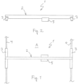
Figure 1 is a top view of a simplified bridge crane; -
Figure 2 is a side view of the bridge crane ofFigure 1 , the bridge crane having symmetrical ends of the main girder; -
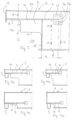
Figure 3 is a side view of an end of the inventive main girder of the bridge crane, where the end is supported on the main girder; -
Figures 4a to 4d show inventive main girder ends of different shapes, where the end is supported on the main girder; -
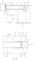
Figure 5 is a side view of an end of the inventive main girder of the bridge crane, where the end is supported to a side of the main girder; -
Figure 6 shows a partial horizontal cross section from above the knife plate at the main girder ends according to the preceding figures; -
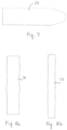
Figure 7 is a top view of the basic shape of the knife plate; and -
Figures 8a and 8b show transverse internal intermediate plates of an end of the main girder. - With reference at first to
Figures 1 and 2 , the main components of abridge crane 1 are a horizontalmain girder 2;end girders 3, transverse in relation to themain girder 2, to which themain girder 2 is supported at both of its ends; rails 4 at the sides of a crane space A, along which theend girders 3 run supported by their wheels (not shown); and atrolley 5 moving along themain girder 2, with its hoisting apparatus (not shown). The crane space A next to and around the rails 4 is often limited, and the present invention solves the problems caused by this space restriction. There may be severalmain girders 2 in parallel, whereby atrolley 5 may be supported by severalmain girders 2. - Referring in addition to
Figure 3 , themain girder 2 comprises in this inventive structure an elongated box-typecentral web 6, and typically, an elongated top flange 7 or top plate on its top surface, and anelongated bottom flange 8 on the bottom surface, supported to whichbottom flange 8 thetrolley 5 of this example runs on themain girder 2. Thetrolley 5 could also be supported to the top flange 7. In both cases, it could also be supported to the side surfaces of thecentral web 6. Web plates 6A of thecentral web 6 are interconnected with theintermediate plates Figures 8a and 8b , which can be welded from the outside throughintermittent openings 19 reserved for the purpose. Theintermediate plates openings 19 in connection with combining thecentral webs 6, and the projections are welded in theopenings 19 from outside the main girder. In the same way, thespacer plates - Formed on both ends of the
central web 6, in other words themain girder 2, there is a cutting slot 9 running horizontally in the longitudinal direction of themain girder 2, and connected to this cutting slot 9 there is aknife plate 10 which extends from a bottom 9a of the cutting slot 9 to the end of themain girder 2 for supporting to theend girder 3 whereby the bottom side of theknife plate 10 is free from thecentral web 6 over a specific length from an end surface of themain girder 2 for said support. - Starting from the end surface of the
main girder 2 over a specific length, on the bottom side of theknife plate 10, a part of thecentral web 6 has been cut off with a side profile P of a specific shape to form aspace 11 for ventilation ducts, cable shelves, power supply rail of the crane, etc. - The height for the portion 6a of the
central web 6 over thespace 11, and thereforeknife plate 10, is selected depending on the maximum weight to be placed on themain girder 2. The minimum height of the portion 6a may typically be approximately 1/5 of the total height of thecentral web 6, such as 150 mm. This ensures that the shearing stress caused by the weight of themain girder 2 andtrolley 5, as well as the load to be hoisted, may be managed, and that there is room to attach theknife plate 10. - If the
space 11 is "two-piece", as shown inFigure 3 , and has aspace 11a extending to the bottom surface of theknife plate 10, and a space 11b in which thecentral web 6 extends to the selected depth below theknife plate 10, the minimum height of thecentral web 6 at this place depends on the length of the space 11b in the main girder's 2 direction when thespace 11 is typically only of the width required by the support to theend girder 3. When theareas 11a, 11b are mainly rectangular, it is simple to give design instructions for them as well as the allowed main dimensions for the joining areas for various loading situations. Programming mainly rectangular shapes in sheet work to manufacture sheets is also simple. The position in the height direction of theknife plate 10 in thecentral web 6 as well as the shape and size of thespace 11 therefore entirely depend on the loading and application of thebridge crane 1 and may greatly vary, the essential matter being the cutting slot 9 and theknife plate 10 therein, the positioning of the succeedingintermediate plates reinforcement plate 13 at the end of theknife plate 10. InFigure 3 , touching the space 11b on the right, a substantiallyvertical closing plate 20 is adapted between the web plates 6A, which at the bottom borders on thebottom flange 8 and on theknife plate 10 at the top. This closingplate 20 is welded from the space 11b side with a uniform weld, from left to right inFigure 3 , so that the weld forms the letter U. The bottom edge is placed on thebottom flange 8, the vertical portions on the inner surfaces of the web plates 6A, as high as welding allows. Theend plate 12 andclosing plate 20 close the end area of themain girder 2, but perfect sealing is not necessary achieved. The volume defined by thespaces 11a, 11b,knife plate 10, and closingplate 20 in the structure is advantageously open at the bottom. The rightangled outer edge of thecentral web 6, shown at the junction of thespaces 11a, 11b, and the inner edge defined by the radius of curvature at the edge of the space 11b may naturally be formed in various ways. The essential matter in the dimensioning of themain girder 2 is to manage the total deflection of themain girder 2 within the allowed limits. - A
support plate 15 may be advantageously connected to the free bottom surface of theknife plate 10, for supporting to theend girder 3. - In the example described, an
end plate 12 is fixed to the end surface of themain girder 2 and the end of theknife plate 10, and a stress-distributingreinforcement plate 13 is fixed on both sides of thecentral web 6 in the area on the side of the bottom 9a of the cutting slot 9, the reinforcement plate extending on a specified area on the front, rear, top and bottom side of the bottom 9a of the cutting slot 9. Thisreinforcement plate 13 is used to ease up the stress concentration at the end of theknife plate 10, and possibly likewise the surrounding stress concentrations around the openings and gaps. The material thickness of thereinforcement plate 13 is advantageously the same as the material thickness of the web plates 6A. Thereinforcement plate 13 is advantageously a square or rectangle, and it has longitudinal through-openings 13a made in it. Theseopenings 13a are advantageously placed horizontally in the assembly, that is, in the direction of the length of themain girder 2. The dimensioning for theopenings 13a is so chosen that a fillet weld may be made at the top edge and bottom edge of theopening 13a, also horizontally, when thereinforcement plate 13 is placed on thecentral web 6. There is need to weld the outer edges of thereinforcement plate 13. The weld slightly resembles a plug weld which is expanded for the dimension of theelongated opening 13a in themain girder 2 direction, but differs from a plug weld in that two parallel fillet welds are enough, and the entire open space of the opening need not be filled with a weld. The goal is to make welding and placing a welding tool easier, so that the top flange 7 is not on the extension of the welding tool or hand. The bottom edge of theend plate 12 is advantageously extended downwards, whereby an edge support can be formed to support thesupport plate 15 laterally. When a sliding joint as the one described in the patent applicationPCT/FI2019/050298 extended end plate 12. In a sliding joint, the potential falling of themain girder 2 from theend girder 3 is also prevented by means of theend plate 12. The main task of theend plate 12 is to block the box structure of the main girder and to stiffen the structure to some extend at this location. Theend plate 12 is more important below in the "Side Connection" solution, to be described below inFigure 5 , in which forces are brought through it from themain girder 2 to a flank of theend girder 3. Thesupport plate 15 is advantageously a rectangular plate that has free holes for a bolt connection between theend girder 3 andknife plate 10. Different options exist for fastening the support plate 15: a bolt joint, weld joint, and a sliding joint made with bolts. Between themain girder 2 and endgirder 3, on at least one end, there is a sliding joint to restrain the movements and stresses of the bridge crane. - The fastenings of the
knife plate 10,end plate 12, andreinforcement plate 13 are most advantageously done by welding. Theknife plate 10 is advantageously welded on its entire length to thecentral web 6, so on the top and bottom sides. Thereinforcement plate 13 is placed on the weldedknife plate 10 and welded in place by making horizontal fillet welds, for example 2+2 pcs. on the edges of theopen slots 13a, and the point of theknife plate 10 end andreinforcement plate 13 is welded with a filled weld. - In addition, advantageously formed in the web portion below the
knife plate 10, there is aprojection 14 in contact with the bottom surface of theknife plate 10 and extending towards the end surface of themain girder 2. Thisprojection 14 bears significance from the viewpoint of the service life of the joint of theknife plate 10, because thisprojection 14 reduces the stress concentration at the joint edges and prolongs the lifespan of this detail. The height of theprojection 14 may be set to constant, but so that it nevertheless has a minimum dimension. By setting a minimum, the goal is to ensure that at least some of theprojection 14 is left even when the welding heat seeks to melt the projection on the edge. Below theprojection 14, there is a notch rounded with a 90 degree arch length, in which a standard radius of curvature may advantageously be used, even though the end area is often designed differently in relation to the need of thespace 11. - When the
knife plate 10 andbottom flange 8 are substantially of the same thickness, theknife plate 10 acts, in a manner of speaking, as an extension of thebottom flange 8 in the area of the portion, i.e.space 11, cut off thecentral web 6 from below theknife plate 10, and on an area even longer, taking loads on themain girder 2 to its end. From the viewpoint of shifting loads, it is possible to set a dimension s1 for the longitudinal overlap in the length direction of themain girder 2, which dimension s1 is restricted on the one hand by the joint to thecentral web 6 of the tip flank seen on the outside of the trapezium of theknife plate 10 at thereinforcement plate 13, and on the other hand the joint between thecentral web 6 andbottom flange 8, at the outermost point closer to the end on theend girder 3 side. The overlap dimension s1 may be 200 to 1000 mm. Theknife plate 10 is advantageously cut off a thicker plate than the web plates 6A orreinforcement plates 13 whereby theknife plate 10 edges may remain uneven or differ from a right angle in relation to the plane surface (top of bottom surface). In this case, it is advantageous that complex forms are not made on theknife plate 10 edges, or that there is no need to connect precisely to these edges. It is wellfounded in this case to connect theknife plate 10 by its straight plane surfaces, so top of bottom surface, as shown inFigure 3 , for example. Similarly, the possible slots are more preferably made in thin plates, such as thecentral web 6 andreinforcement plates 13. - When the inventive cutting slot -
knife plate structure 9, 10 is at both ends of themain girder 2, thesestructures 9, 10 do not have to be identical but they can be made according to the requirements and application of the customer. If there are several main girders side-by-side, such as two main girders to support thetrolley 5, as many as 4 different ends of the main girder may be formed, if so required. -
Figures 4a to 4b show, by way of example, what kind of different shapes for the ends of themain girder 2 are implementable with the present invention. The connecting area of themain girder 2 need not be alike at both ends of the main girder. The area 11b inFigure 3 may be separately modified for both connection areas of themain girder 2 according to the space needs of the customer. It may be considered worth pursuing that the height of the support for theend girders 3 is the same at both ends of themain girder 2 so that themain girder 2 is not tilted. In some cases, themain girder 2 of a bridge crane, gantry crane, or semi-gantry crane is adapted to move on rails 4 that are at two different height positions. Even in such a case, themain girder 2 or part thereof is substantially horizontal. - The
knife plate 10 is advantageously a rectangle which is narrowed at its end into the shape of a trapezium. The width of theknife plate 10 on the portion of its rectangle is advantageously 2 to 4 times the distance between the web plates 6A. Theknife plate 10 is advantageously not wider than the width of thebottom flange 8. The thin tip of the trapezium may be substantially the same as the distance between the web plates 6A of thecentral web 6. The tip may show a projection protruding forward on the front side of the tip, the width of which substantially corresponds with the width between the inner surfaces of the web plates 6A. This projection makes the assembly of the web plates 6A easier at the manufacture. As an alternative embodiment for theknife plate 10, instead of the trapezium tip there may be a fork-type tip in which the branches of the fork become gentler within themain girder 2, and the local stress peak on the flanks of the web plates 6A can be evened out over the corresponding joint length. The fork may be shaped as a parabola, for example, in which the parabola opens towards the centre part of themain girder 2. In this embodiment, thereinforcement plates 13 may in an advantageous case be left out. On the other hand, the projection at the tip of the trapezium cannot be utilised in the assembly. Theknife plate 10 is advantageously a plate-like material which is of similar material within themain girder 2 and internally connects the joints of the cutting slots 9 made in thecentral web 6 and theknife plate 10. Due to the structure, theknife plate 10 may support thecentral webs 6 from the inside and transfer forces between thecentral webs 6. - As shown in
Figure 5 , themain girder 3 according to the invention may be alternatively connected to the side of theend plate 12, forming the so-called "Side Connection" fastening. In such a case, theend plate 12 is selected from a stronger material thickness than in the "Top Medium" fastening described first, and theend plate 12 is also wider (i.e. longer in the direction of the end girder 3) to form bolt joints between theend plate 12 andend girder 3. In this "Side Connection" fastening, thespace 11 may potentially be smaller than in the "Top Medium" fastening, because the end surface of themain girder 2 in the longitudinal direction of themain girder 2 faces away from theend girder 3 by the width of theend girder 3 as compared to the "Top Medium" fastening. - The above description of the invention is only intended to illustrate the basic idea of the invention. A person skilled in the art may, however, implement its details within the scope of the attached claims.
Claims (12)
- A main girder (2) of a bridge crane, intended to be supported by its ends to end girders (3) of the bridge crane (1) and which comprises an elongated box-type central web (6) having vertical web plates (6A), characterised in that there is, formed in the web plates (6A) of the central web (6) on at least one end of the main girder (2), a cutting slot (9) running substantially in the longitudinal direction of the main girder (2), and connected to this cutting slot (9) there is a knife plate (10) which extends in a horizontal plane from a bottom (9a) of the cutting slot (9) substantially to the end of the main girder (2), for supporting to the end girder (3).
- A main girder as claimed in claim 1, characterised in that starting from the end surface of the main girder (2) over a specific length, on the bottom side of the knife plate (10), a part of the central web (6) has been cut off with a side profile (P) of a specific shape to form a space (11) for ventilation ducts, cable shelves, power supply rail of the crane, etc.
- A main girder as claimed in claim 1 or 2, characterised in that the bottom side of the knife plate (10) is substantially free from the central web (6) over a specific length from an end surface of the main girder (2), for supporting to the end girder (2).
- A main girder as claimed in claim 3, characterised in that a support plate (15) is fixed to the free bottom surface of the knife plate (10), for supporting to the end girder (3).
- A main girder as claimed in any one of the preceding claims, char-acterised in that an end plate (12) is attached to the end surface of the main girder (2) and the end of the knife plate (10).
- A main girder as claimed in claim 1 or 2, characterised in that attached to the end surface of the main girder (2) and the end of the knife plate (10) there is attached an end plate (12) from which the end of the main girder (2) is intended to be supported to the end girder (3).
- A main girder as claimed in any one of the preceding claims, char-acterised in that a stress-distributing reinforcement plate (13) is fixed on both sides of the central web (6) in the area on the side of the bottom (9a) of the cutting slot (9), the reinforcement plate extending on a specified area on the front, rear, top and bottom side of the bottom (9a) of the cutting slot (9).
- A main girder as claimed in any one of the preceding claims, char-acterised in that formed in the web portion below the knife plate (10), there is a projection (14) in contact with the bottom surface of the knife plate (10) and extending towards the end surface of the main girder (2).
- A main girder as claimed in any one of the preceding claims, char-acterised in that the fastenings of the knife plate (10), end plate (12), and reinforcement plate (13) are done by welding.
- A main girder as claimed in any one of the preceding claims, char-acterised in that an elongated top flange (7) or top plate is arranged in the top part of the central web (6), and an elongated bottom flange (8) is arranged in the bottom part of the central web (6).
- A main girder as claimed in claim 10, characterised in that the knife plate (10) and lower flange (8) are substantially equally thick.
- A main girder as claimed in any one of the preceding claims, char-acterised in that a cutting slot (9) and a knife plate (10) are arranged at both ends of the main girder (2).
Applications Claiming Priority (2)
| Application Number | Priority Date | Filing Date | Title |
|---|---|---|---|
| FI20196016A FI130235B (en) | 2019-11-26 | 2019-11-26 | The main supporter of the bridge crane |
| PCT/FI2020/050795 WO2021105562A1 (en) | 2019-11-26 | 2020-11-25 | Main girder of bridge crane |
Publications (3)
| Publication Number | Publication Date |
|---|---|
| EP4065502A1 EP4065502A1 (en) | 2022-10-05 |
| EP4065502A4 EP4065502A4 (en) | 2023-01-25 |
| EP4065502B1 true EP4065502B1 (en) | 2025-01-01 |
Family
ID=76129265
Family Applications (1)
| Application Number | Title | Priority Date | Filing Date |
|---|---|---|---|
| EP20892947.1A Active EP4065502B1 (en) | 2019-11-26 | 2020-11-25 | Main girder of bridge crane |
Country Status (8)
| Country | Link |
|---|---|
| US (1) | US12129155B2 (en) |
| EP (1) | EP4065502B1 (en) |
| CN (1) | CN114867680B (en) |
| AU (1) | AU2020392730B2 (en) |
| BR (1) | BR112022010332A2 (en) |
| CA (1) | CA3158410C (en) |
| FI (1) | FI130235B (en) |
| WO (1) | WO2021105562A1 (en) |
Families Citing this family (2)
| Publication number | Priority date | Publication date | Assignee | Title |
|---|---|---|---|---|
| CN115288430A (en) * | 2022-08-15 | 2022-11-04 | 中国建筑第八工程局有限公司 | Column formwork installation reinforcing device and reinforcing method thereof |
| CN119873611B (en) * | 2025-03-17 | 2025-09-23 | 上海振华重工(集团)股份有限公司 | Method and structure for preventing water accumulation of shore bridge girder and girder preparation method |
Citations (4)
| Publication number | Priority date | Publication date | Assignee | Title |
|---|---|---|---|---|
| GB1068184A (en) * | 1963-05-03 | 1967-05-10 | Babcock & Wilcox Ltd | Improvements in travelling cranes |
| US3404640A (en) * | 1966-03-24 | 1968-10-08 | Morgan Engineering Co | Traveling crane truck of saddle and pin construction |
| DE2556246A1 (en) * | 1975-12-13 | 1977-06-16 | Ver Flugtechnische Werke | Metal plate with stiffening rib - has rib welded to stub formed integrally on plate by rolling |
| WO2012148260A1 (en) * | 2011-04-26 | 2012-11-01 | Anne Pieter Van Driesum | Composite floor and girder for that purpose |
Family Cites Families (19)
| Publication number | Priority date | Publication date | Assignee | Title |
|---|---|---|---|---|
| US3294252A (en) * | 1962-12-06 | 1966-12-27 | Ishikawajima Harima Heavy Ind | Crane girders |
| BE663701A (en) * | 1963-06-12 | |||
| JPS528194Y2 (en) * | 1973-03-02 | 1977-02-21 | ||
| FR2195759B1 (en) * | 1973-09-05 | 1975-04-04 | Crane | |
| FI105266B (en) | 1998-05-28 | 2000-07-14 | Kci Kone Cranes Int Oy | Overhead Crane |
| AT10850U1 (en) * | 2007-04-27 | 2009-11-15 | Josef Dipl Ing Hirschlager | RUNNING CRANE BRIDGE |
| DE202008005769U1 (en) * | 2008-04-25 | 2008-08-14 | Hörschläger, Josef | Traveling crane bridge |
| KR20100083434A (en) * | 2009-01-13 | 2010-07-22 | (주) 세신기계 | Safety-improved over head crane |
| KR101487885B1 (en) * | 2012-08-10 | 2015-01-29 | 채일수 | The crane girder as a traveling rail |
| DE102012109588A1 (en) * | 2012-10-09 | 2014-04-10 | Demag Cranes & Components Gmbh | Crane, in particular overhead crane or gantry crane, with at least one crane girder |
| DE102012109586A1 (en) * | 2012-10-09 | 2014-04-10 | Demag Cranes & Components Gmbh | Crane, in particular overhead crane or gantry crane, with at least two crane girders |
| DE102015101756A1 (en) * | 2015-02-06 | 2016-08-11 | Terex MHPS IP Management GmbH | Crane, in particular overhead crane or gantry crane, with at least one crane girder |
| CN106744298A (en) * | 2017-03-29 | 2017-05-31 | 郑州大学 | A kind of crane main beam structure |
| CN207596326U (en) | 2017-12-15 | 2018-07-10 | 云南昆钢重型装备制造集团有限公司 | A kind of electric single beam crane connection between girder and carriage structure that can improve stability |
| CN108382989B (en) * | 2018-03-07 | 2019-10-11 | 宁夏天地奔牛银起设备有限公司 | Manufacturing method of middle rail box girder of large tonnage bridge crane |
| FI128020B (en) * | 2018-04-20 | 2019-08-15 | Konecranes Global Oy | Bridge crane arrangement |
| CN110626936A (en) * | 2019-10-29 | 2019-12-31 | 法兰泰克重工股份有限公司 | A lifting lug installation structure and a crane |
| CN114634103B (en) * | 2022-03-24 | 2025-09-02 | 河南省矿山起重机有限公司 | Main beam of crane and crane |
| CN116730186B (en) * | 2023-07-12 | 2026-04-17 | 光明起重集团有限公司 | A crane drive device |
-
2019
- 2019-11-26 FI FI20196016A patent/FI130235B/en active
-
2020
- 2020-11-25 US US17/756,345 patent/US12129155B2/en active Active
- 2020-11-25 EP EP20892947.1A patent/EP4065502B1/en active Active
- 2020-11-25 CA CA3158410A patent/CA3158410C/en active Active
- 2020-11-25 AU AU2020392730A patent/AU2020392730B2/en active Active
- 2020-11-25 CN CN202080082059.3A patent/CN114867680B/en active Active
- 2020-11-25 WO PCT/FI2020/050795 patent/WO2021105562A1/en not_active Ceased
- 2020-11-25 BR BR112022010332A patent/BR112022010332A2/en active Search and Examination
Patent Citations (4)
| Publication number | Priority date | Publication date | Assignee | Title |
|---|---|---|---|---|
| GB1068184A (en) * | 1963-05-03 | 1967-05-10 | Babcock & Wilcox Ltd | Improvements in travelling cranes |
| US3404640A (en) * | 1966-03-24 | 1968-10-08 | Morgan Engineering Co | Traveling crane truck of saddle and pin construction |
| DE2556246A1 (en) * | 1975-12-13 | 1977-06-16 | Ver Flugtechnische Werke | Metal plate with stiffening rib - has rib welded to stub formed integrally on plate by rolling |
| WO2012148260A1 (en) * | 2011-04-26 | 2012-11-01 | Anne Pieter Van Driesum | Composite floor and girder for that purpose |
Also Published As
| Publication number | Publication date |
|---|---|
| CA3158410A1 (en) | 2021-06-03 |
| BR112022010332A2 (en) | 2022-08-16 |
| AU2020392730B2 (en) | 2023-11-23 |
| CN114867680A (en) | 2022-08-05 |
| EP4065502A1 (en) | 2022-10-05 |
| FI20196016A1 (en) | 2021-05-27 |
| CN114867680B (en) | 2025-11-25 |
| AU2020392730A1 (en) | 2022-06-02 |
| US12129155B2 (en) | 2024-10-29 |
| FI130235B (en) | 2023-05-04 |
| US20230348235A1 (en) | 2023-11-02 |
| WO2021105562A1 (en) | 2021-06-03 |
| EP4065502A4 (en) | 2023-01-25 |
| CA3158410C (en) | 2025-03-11 |
Similar Documents
| Publication | Publication Date | Title |
|---|---|---|
| KR101996114B1 (en) | Crane, particularly bridge crane or gantry crane, comprising at least one crane girder | |
| US12129155B2 (en) | Main girder of bridge crane | |
| CN112575622B (en) | Rail beams, rail beam elements and rail beams for rail vehicles | |
| RU2669471C1 (en) | Hoisting bridge or gantry crane with not less than one span beam | |
| RU2591778C1 (en) | Hoisting bridge or gantry crane with not less than one span beam | |
| JP2013537159A (en) | Two rail device | |
| KR20120126099A (en) | Beam in a vehicle door and a method of rustproofing a vehicle door | |
| JP2018504336A5 (en) | ||
| CN108025894A (en) | Crane including at least one Crane Beam, particularly bridge crane or gantry crane | |
| KR101032366B1 (en) | Horizontal load supporting structure of integrated crane by multi-purpose inspection | |
| EP3184812A1 (en) | Curved cross-section wind turbine tower and wind turbine comprising said tower | |
| KR20200140829A (en) | Box girder, in particular, crane girder, and crane having same, and method for manufacturing same | |
| EP3781512B1 (en) | Bridge crane arrangement | |
| US20060208534A1 (en) | Construction element and a vehicle frame comprising such a construction element | |
| CN109264594B (en) | box beam | |
| JP2020148009A (en) | Deck receiving material and how to attach the deck receiving material | |
| KR20170071484A (en) | Boom arm and concrete-distributing boom | |
| CN115492239A (en) | Conversion beam column node and construction process thereof | |
| JP7115324B2 (en) | Steel member reinforcement structure and reinforcement method | |
| US20220332547A1 (en) | Support for a trolley, and overhead transport device having such a support | |
| EP4472918B1 (en) | Rail joints | |
| CN108978497B (en) | Partitioning processing and split mounting method for embedded steel shell of continuous beam | |
| CN112282209A (en) | H-shaped steel beam with T-shaped ends and machining method thereof | |
| RU2317931C2 (en) | Overhead conveyer | |
| JP2023133419A (en) | Joint structure, structure, and structure |
Legal Events
| Date | Code | Title | Description |
|---|---|---|---|
| STAA | Information on the status of an ep patent application or granted ep patent |
Free format text: STATUS: THE INTERNATIONAL PUBLICATION HAS BEEN MADE |
|
| PUAI | Public reference made under article 153(3) epc to a published international application that has entered the european phase |
Free format text: ORIGINAL CODE: 0009012 |
|
| STAA | Information on the status of an ep patent application or granted ep patent |
Free format text: STATUS: REQUEST FOR EXAMINATION WAS MADE |
|
| 17P | Request for examination filed |
Effective date: 20220530 |
|
| AK | Designated contracting states |
Kind code of ref document: A1 Designated state(s): AL AT BE BG CH CY CZ DE DK EE ES FI FR GB GR HR HU IE IS IT LI LT LU LV MC MK MT NL NO PL PT RO RS SE SI SK SM TR |
|
| A4 | Supplementary search report drawn up and despatched |
Effective date: 20230103 |
|
| RIC1 | Information provided on ipc code assigned before grant |
Ipc: E04C 3/06 20060101ALI20221221BHEP Ipc: B66C 17/00 20060101ALI20221221BHEP Ipc: F16S 3/00 20060101ALI20221221BHEP Ipc: E04G 11/54 20060101ALI20221221BHEP Ipc: E04C 3/04 20060101ALI20221221BHEP Ipc: E04B 1/342 20060101ALI20221221BHEP Ipc: E04B 1/24 20060101ALI20221221BHEP Ipc: E04B 1/08 20060101ALI20221221BHEP Ipc: E01D 19/00 20060101ALI20221221BHEP Ipc: E01D 18/00 20060101ALI20221221BHEP Ipc: E01D 12/00 20060101ALI20221221BHEP Ipc: E01D 2/00 20060101ALI20221221BHEP Ipc: E01D 1/00 20060101ALI20221221BHEP Ipc: B66C 19/00 20060101ALI20221221BHEP Ipc: B66C 6/00 20060101AFI20221221BHEP |
|
| DAV | Request for validation of the european patent (deleted) | ||
| DAX | Request for extension of the european patent (deleted) | ||
| P01 | Opt-out of the competence of the unified patent court (upc) registered |
Effective date: 20230527 |
|
| STAA | Information on the status of an ep patent application or granted ep patent |
Free format text: STATUS: EXAMINATION IS IN PROGRESS |
|
| 17Q | First examination report despatched |
Effective date: 20231212 |
|
| GRAP | Despatch of communication of intention to grant a patent |
Free format text: ORIGINAL CODE: EPIDOSNIGR1 |
|
| STAA | Information on the status of an ep patent application or granted ep patent |
Free format text: STATUS: GRANT OF PATENT IS INTENDED |
|
| INTG | Intention to grant announced |
Effective date: 20240625 |
|
| GRAS | Grant fee paid |
Free format text: ORIGINAL CODE: EPIDOSNIGR3 |
|
| GRAA | (expected) grant |
Free format text: ORIGINAL CODE: 0009210 |
|
| STAA | Information on the status of an ep patent application or granted ep patent |
Free format text: STATUS: THE PATENT HAS BEEN GRANTED |
|
| AK | Designated contracting states |
Kind code of ref document: B1 Designated state(s): AL AT BE BG CH CY CZ DE DK EE ES FI FR GB GR HR HU IE IS IT LI LT LU LV MC MK MT NL NO PL PT RO RS SE SI SK SM TR |
|
| REG | Reference to a national code |
Ref country code: GB Ref legal event code: FG4D |
|
| REG | Reference to a national code |
Ref country code: DE Ref legal event code: R096 Ref document number: 602020044306 Country of ref document: DE |
|
| REG | Reference to a national code |
Ref country code: CH Ref legal event code: EP |
|
| REG | Reference to a national code |
Ref country code: IE Ref legal event code: FG4D |
|
| REG | Reference to a national code |
Ref country code: LT Ref legal event code: MG9D |
|
| REG | Reference to a national code |
Ref country code: NL Ref legal event code: MP Effective date: 20250101 |
|
| REG | Reference to a national code |
Ref country code: AT Ref legal event code: MK05 Ref document number: 1756071 Country of ref document: AT Kind code of ref document: T Effective date: 20250101 |
|
| PG25 | Lapsed in a contracting state [announced via postgrant information from national office to epo] |
Ref country code: NL Free format text: LAPSE BECAUSE OF FAILURE TO SUBMIT A TRANSLATION OF THE DESCRIPTION OR TO PAY THE FEE WITHIN THE PRESCRIBED TIME-LIMIT Effective date: 20250101 |
|
| PG25 | Lapsed in a contracting state [announced via postgrant information from national office to epo] |
Ref country code: FI Free format text: LAPSE BECAUSE OF FAILURE TO SUBMIT A TRANSLATION OF THE DESCRIPTION OR TO PAY THE FEE WITHIN THE PRESCRIBED TIME-LIMIT Effective date: 20250101 |
|
| PG25 | Lapsed in a contracting state [announced via postgrant information from national office to epo] |
Ref country code: PL Free format text: LAPSE BECAUSE OF FAILURE TO SUBMIT A TRANSLATION OF THE DESCRIPTION OR TO PAY THE FEE WITHIN THE PRESCRIBED TIME-LIMIT Effective date: 20250101 |
|
| PG25 | Lapsed in a contracting state [announced via postgrant information from national office to epo] |
Ref country code: ES Free format text: LAPSE BECAUSE OF FAILURE TO SUBMIT A TRANSLATION OF THE DESCRIPTION OR TO PAY THE FEE WITHIN THE PRESCRIBED TIME-LIMIT Effective date: 20250101 |
|
| PG25 | Lapsed in a contracting state [announced via postgrant information from national office to epo] |
Ref country code: NO Free format text: LAPSE BECAUSE OF FAILURE TO SUBMIT A TRANSLATION OF THE DESCRIPTION OR TO PAY THE FEE WITHIN THE PRESCRIBED TIME-LIMIT Effective date: 20250401 Ref country code: IS Free format text: LAPSE BECAUSE OF FAILURE TO SUBMIT A TRANSLATION OF THE DESCRIPTION OR TO PAY THE FEE WITHIN THE PRESCRIBED TIME-LIMIT Effective date: 20250501 |
|
| PG25 | Lapsed in a contracting state [announced via postgrant information from national office to epo] |
Ref country code: HR Free format text: LAPSE BECAUSE OF FAILURE TO SUBMIT A TRANSLATION OF THE DESCRIPTION OR TO PAY THE FEE WITHIN THE PRESCRIBED TIME-LIMIT Effective date: 20250101 |
|
| PG25 | Lapsed in a contracting state [announced via postgrant information from national office to epo] |
Ref country code: LV Free format text: LAPSE BECAUSE OF FAILURE TO SUBMIT A TRANSLATION OF THE DESCRIPTION OR TO PAY THE FEE WITHIN THE PRESCRIBED TIME-LIMIT Effective date: 20250101 Ref country code: PT Free format text: LAPSE BECAUSE OF FAILURE TO SUBMIT A TRANSLATION OF THE DESCRIPTION OR TO PAY THE FEE WITHIN THE PRESCRIBED TIME-LIMIT Effective date: 20250502 |
|
| PG25 | Lapsed in a contracting state [announced via postgrant information from national office to epo] |
Ref country code: GR Free format text: LAPSE BECAUSE OF FAILURE TO SUBMIT A TRANSLATION OF THE DESCRIPTION OR TO PAY THE FEE WITHIN THE PRESCRIBED TIME-LIMIT Effective date: 20250402 Ref country code: BG Free format text: LAPSE BECAUSE OF FAILURE TO SUBMIT A TRANSLATION OF THE DESCRIPTION OR TO PAY THE FEE WITHIN THE PRESCRIBED TIME-LIMIT Effective date: 20250101 |
|
| PG25 | Lapsed in a contracting state [announced via postgrant information from national office to epo] |
Ref country code: AT Free format text: LAPSE BECAUSE OF FAILURE TO SUBMIT A TRANSLATION OF THE DESCRIPTION OR TO PAY THE FEE WITHIN THE PRESCRIBED TIME-LIMIT Effective date: 20250101 |
|
| PG25 | Lapsed in a contracting state [announced via postgrant information from national office to epo] |
Ref country code: CZ Free format text: LAPSE BECAUSE OF FAILURE TO SUBMIT A TRANSLATION OF THE DESCRIPTION OR TO PAY THE FEE WITHIN THE PRESCRIBED TIME-LIMIT Effective date: 20250101 |
|
| PG25 | Lapsed in a contracting state [announced via postgrant information from national office to epo] |
Ref country code: SE Free format text: LAPSE BECAUSE OF FAILURE TO SUBMIT A TRANSLATION OF THE DESCRIPTION OR TO PAY THE FEE WITHIN THE PRESCRIBED TIME-LIMIT Effective date: 20250101 |
|
| REG | Reference to a national code |
Ref country code: DE Ref legal event code: R097 Ref document number: 602020044306 Country of ref document: DE |
|
| PG25 | Lapsed in a contracting state [announced via postgrant information from national office to epo] |
Ref country code: SM Free format text: LAPSE BECAUSE OF FAILURE TO SUBMIT A TRANSLATION OF THE DESCRIPTION OR TO PAY THE FEE WITHIN THE PRESCRIBED TIME-LIMIT Effective date: 20250101 |
|
| PG25 | Lapsed in a contracting state [announced via postgrant information from national office to epo] |
Ref country code: DK Free format text: LAPSE BECAUSE OF FAILURE TO SUBMIT A TRANSLATION OF THE DESCRIPTION OR TO PAY THE FEE WITHIN THE PRESCRIBED TIME-LIMIT Effective date: 20250101 |
|
| PG25 | Lapsed in a contracting state [announced via postgrant information from national office to epo] |
Ref country code: IT Free format text: LAPSE BECAUSE OF FAILURE TO SUBMIT A TRANSLATION OF THE DESCRIPTION OR TO PAY THE FEE WITHIN THE PRESCRIBED TIME-LIMIT Effective date: 20250101 |
|
| PG25 | Lapsed in a contracting state [announced via postgrant information from national office to epo] |
Ref country code: EE Free format text: LAPSE BECAUSE OF FAILURE TO SUBMIT A TRANSLATION OF THE DESCRIPTION OR TO PAY THE FEE WITHIN THE PRESCRIBED TIME-LIMIT Effective date: 20250101 |
|
| PG25 | Lapsed in a contracting state [announced via postgrant information from national office to epo] |
Ref country code: RO Free format text: LAPSE BECAUSE OF FAILURE TO SUBMIT A TRANSLATION OF THE DESCRIPTION OR TO PAY THE FEE WITHIN THE PRESCRIBED TIME-LIMIT Effective date: 20250101 |
|
| PG25 | Lapsed in a contracting state [announced via postgrant information from national office to epo] |
Ref country code: SK Free format text: LAPSE BECAUSE OF FAILURE TO SUBMIT A TRANSLATION OF THE DESCRIPTION OR TO PAY THE FEE WITHIN THE PRESCRIBED TIME-LIMIT Effective date: 20250101 |
|
| PLBE | No opposition filed within time limit |
Free format text: ORIGINAL CODE: 0009261 |
|
| STAA | Information on the status of an ep patent application or granted ep patent |
Free format text: STATUS: NO OPPOSITION FILED WITHIN TIME LIMIT |
|
| 26N | No opposition filed |
Effective date: 20251002 |
|
| PGFP | Annual fee paid to national office [announced via postgrant information from national office to epo] |
Ref country code: DE Payment date: 20251118 Year of fee payment: 6 |
|
| PGFP | Annual fee paid to national office [announced via postgrant information from national office to epo] |
Ref country code: GB Payment date: 20251120 Year of fee payment: 6 |
|
| PGFP | Annual fee paid to national office [announced via postgrant information from national office to epo] |
Ref country code: FR Payment date: 20251120 Year of fee payment: 6 |