EP4064453B1 - 5g-antenne und strahlungseinheit dafür - Google Patents
5g-antenne und strahlungseinheit dafür Download PDFInfo
- Publication number
- EP4064453B1 EP4064453B1 EP20903178.0A EP20903178A EP4064453B1 EP 4064453 B1 EP4064453 B1 EP 4064453B1 EP 20903178 A EP20903178 A EP 20903178A EP 4064453 B1 EP4064453 B1 EP 4064453B1
- Authority
- EP
- European Patent Office
- Prior art keywords
- radiation
- extension branch
- extension
- branch
- arms
- Prior art date
- Legal status (The legal status is an assumption and is not a legal conclusion. Google has not performed a legal analysis and makes no representation as to the accuracy of the status listed.)
- Active
Links
Images


Classifications
-
- H—ELECTRICITY
- H01—ELECTRIC ELEMENTS
- H01Q—ANTENNAS, i.e. RADIO AERIALS
- H01Q1/00—Details of, or arrangements associated with, antennas
- H01Q1/36—Structural form of radiating elements, e.g. cone, spiral, umbrella; Particular materials used therewith
- H01Q1/38—Structural form of radiating elements, e.g. cone, spiral, umbrella; Particular materials used therewith formed by a conductive layer on an insulating support
-
- H—ELECTRICITY
- H01—ELECTRIC ELEMENTS
- H01Q—ANTENNAS, i.e. RADIO AERIALS
- H01Q25/00—Antennas or antenna systems providing at least two radiating patterns
- H01Q25/001—Crossed polarisation dual antennas
-
- H—ELECTRICITY
- H01—ELECTRIC ELEMENTS
- H01Q—ANTENNAS, i.e. RADIO AERIALS
- H01Q1/00—Details of, or arrangements associated with, antennas
- H01Q1/12—Supports; Mounting means
- H01Q1/22—Supports; Mounting means by structural association with other equipment or articles
- H01Q1/24—Supports; Mounting means by structural association with other equipment or articles with receiving set
- H01Q1/241—Supports; Mounting means by structural association with other equipment or articles with receiving set used in mobile communications, e.g. GSM
- H01Q1/246—Supports; Mounting means by structural association with other equipment or articles with receiving set used in mobile communications, e.g. GSM specially adapted for base stations
-
- H—ELECTRICITY
- H01—ELECTRIC ELEMENTS
- H01Q—ANTENNAS, i.e. RADIO AERIALS
- H01Q1/00—Details of, or arrangements associated with, antennas
- H01Q1/50—Structural association of antennas with earthing switches, lead-in devices or lightning protectors
-
- H—ELECTRICITY
- H01—ELECTRIC ELEMENTS
- H01Q—ANTENNAS, i.e. RADIO AERIALS
- H01Q21/00—Antenna arrays or systems
- H01Q21/0006—Particular feeding systems
-
- H—ELECTRICITY
- H01—ELECTRIC ELEMENTS
- H01Q—ANTENNAS, i.e. RADIO AERIALS
- H01Q21/00—Antenna arrays or systems
- H01Q21/24—Combinations of antenna units polarised in different directions for transmitting or receiving circularly and elliptically polarised waves or waves linearly polarised in any direction
- H01Q21/26—Turnstile or like antennas comprising arrangements of three or more elongated elements disposed radially and symmetrically in a horizontal plane about a common centre
-
- H—ELECTRICITY
- H01—ELECTRIC ELEMENTS
- H01Q—ANTENNAS, i.e. RADIO AERIALS
- H01Q9/00—Electrically-short antennas having dimensions not more than twice the operating wavelength and consisting of conductive active radiating elements
- H01Q9/04—Resonant antennas
- H01Q9/16—Resonant antennas with feed intermediate between the extremities of the antenna, e.g. centre-fed dipole
- H01Q9/28—Conical, cylindrical, cage, strip, gauze, or like elements having an extended radiating surface; Elements comprising two conical surfaces having collinear axes and adjacent apices and fed by two-conductor transmission lines
Definitions
- the present invention relates to the field of communication technologies, and in particular, to a 5G antenna and a radiation unit thereof.
- the 5G network is also gradually entering the commercial stage. Due to higher requirements on antennas by the 5G technology, the antennas are required to have high-rate transmission, larger system capacity, miniaturization, and dual-polarization characteristic simultaneously.
- the low frequency wavelength is longer than the high frequency wavelength, for fixed size radiation unit, when the low frequency and high frequency work at the same time, they tend to interact with each other, thus affecting the radiation unit's frequency band expansion and affecting the radiation performance of the antenna.
- a radiation unit including: two groups of dipoles the polarizations of which are orthogonal, each group of the dipoles includes two radiation arms which are disposed to be spaced apart relative to each other, and each of the radiation arms is provided with a first extension branch and a second extension branch which are disposed to be spaced apart from each other; wherein the surface area of the first extension branch is greater than the surface area of the second extension branch; wherein an outer sidewall of each of the radiation arms is provided with a cut-off corner; wherein each of the radiation arms is provided with a first hollowed groove, each of one end of the first extension branch and one end of the second extension branch is connected with the outer sidewall of each of the radiation arms, a first spacer groove in communication with the first hollowed groove is provided between the first extension branch and the second extension branch, and each of the first extension branch and the second extension branch is disposed towards the inside of the first hollowed groove; wherein a second spacer groove and a current-conducting part
- the radiation unit of the above embodiment includes four radiation arms of the same shape and size, wherein two radiation arms which are disposed to be spaced apart and diagonal relative to each other fit to form a first group of dipoles, the other two radiation arms which are disposed to be spaced apart and diagonal relative to each other fit to form a second group of dipoles, and the two groups of dipoles the polarizations of which are orthogonal to each other are utilized to form dual-polarization radiation.
- the first extension branches and the second extension branches which are disposed to be spaced apart from each other are disposed on respective radiation arms, so that the first extension branches and the second extension branches can be utilized to adjust the electrical lengths of the high frequencies and low frequencies of the radiation unit, thereby being able to achieve extension of the operating frequency band which is more than 20% of the bandwidth, good radiation performance, and fulfil the use requirements of 5G antennas.
- the radiation unit has a simple structure and is easy to produce, and the manufacturing cost is lowered.
- each of the radiation arms is provided with a first connecting portion for coupling feed with a feeding balun.
- a distance between a sidewall of the first hollowed groove and a sidewall of the second spacer groove ranges from 5.5 mm to 6mm; and a width of the second hollowed groove ranges from 11.9 mm to 12.7 mm.
- a 5G antenna including: the radiation unit; and feeding baluns which are in coupling feed with the radiation arms.
- the 5G antenna in the above embodiments when in use, performs coupling feed on the radiation arms by using the feeding baluns, so that it can be ensured that the radiation unit can radiate signals with good radiation performance in a stable and reliable manner.
- the first extension branches and the second extension branches which are disposed to be spaced apart from each other are disposed on respective radiation arms of the radiation unit, thus the first extension branches and the second extension branches can be utilized to adjust the electrical lengths of the high frequencies and low frequencies of the radiation unit, thereby being able to achieve extension of the operating frequency band, achieve a very wide operating frequency band, and fulfil the use requirements of 5G antennas.
- the 5G antenna of the above embodiment in the case of ultra-wideband being implemented, also has good impedance characteristics and cross-polarization ratio, and the production cost is low, which is suitable for the use requirements of 5G technology.
- the radiation unit further includes a substrate which is provided between the radiation arms and the feeding baluns, and the radiation arms are disposed on a surface of the substrate.
- each of the feeding baluns includes a first feeding component for the coupling feed with the first group of dipoles and a second feeding component for the coupling feed with the second group of dipoles, the first feeding component and the second feeding component being disposed to have an angle therebetween.
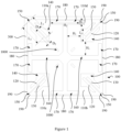
- a radiation unit 10 including two groups of dipoles the polarizations of which are orthogonal, each group of the dipoles includes two radiation arms 110 which are disposed to be spaced apart relative to each other, each of the radiation arms 110 is provided with a first extension branch 120 and a second extension branch 130 which are disposed to be spaced apart from each other.
- the radiation unit 10 of the above embodiment includes four radiation arms 110 of the same shape and size, wherein two radiation arms 110 which are disposed to be spaced apart and diagonal relative to each other fit to form a first group of dipoles, the other two radiation arms 110 which are disposed to be spaced apart and diagonal relative to each other fit to form a second group of dipoles, and the two groups of dipoles the polarizations of which are orthogonal to each other are utilized to form dual-polarization radiation.
- the first extension branches 120 and the second extension branches 130 which are disposed to be spaced apart from each other are disposed on respective radiation arms 110, so that the first extension branches 120 and the second extension branches 130 can be utilized to adjust the electrical lengths of the high frequencies and low frequencies of the radiation unit 10, thereby being able to achieve extension of the operating frequency band which is more than 20% of the bandwidth, good radiation performance, and fulfil the use requirements of 5G antennas.
- the radiation unit 10 has a simple structure and is easy to produce, and the manufacturing cost is lowered.
- first extension branches 120 and the connecting end of the second extension branches 130 may be connected with outer sidewalls of respective radiation arms 110, so that the first extension branches 120 and the second extension branches 130 can flexibly extend towards the outer sides or inner sides of the radiation arms 110.
- the first extension branch 120 and the second extension branch 130 can be formed with the radiation arm 110 in an all-in-one manner or they can be formed separately to be assembled; the all-in-one manufacturing manner is preferred, which is simple and convenient, and lowers the manufacturing cost.
- the first extension branch 120 and the second extension branch 130 can be provided in structures of sheets, strips, etc. As shown in Fig. 1 , the radiation arm 110a and the radiation arm 110b form the first group of dipoles, and the radiation arm 110c and the radiation arm 110d form the second group of dipoles.
- the surface area of the first extension branch 120 and the surface area of the second extension branch 130 can be flexibly adjusted simultaneously or separately according to the actual use cases, as long as the first extension branch 120 and the second extension branch 130 are enabled to extend the operating frequency band of the radiation unit 10.
- the length (Li as shown in Fig. 1 ) of the first extension branch 120 is adjustable. As such, by flexibly adjusting the length of the first extension branch 120, the surface area of the first extension branch 120 is adjusted, the electrical length of the radiation unit 10 is adjusted, and in turn the operating frequency band of the radiation unit 10 is adjusted.
- the length (L 2 as shown in Fig. 1 ) of second extension branch 130 is adjustable. As such, by flexibly adjusting the length of second extension branch 130, the surface area of the second extension branch 130 is adjusted, the electrical length of the radiation unit 10 is adjusted, and in turn the operating frequency band of the radiation unit 10 is adjusted.
- the width (D 2 as shown in Fig. 1 ) of second extension branch 130 is adjustable. As such, by flexibly adjusting the width of second extension branch 130, the surface area of the second extension branch 130 is adjusted, the electrical length of the radiation unit 10 is adjusted, and in turn the operating frequency band of the radiation unit 10 is adjusted.
- flexible adjustment can be at least made to one of the parameters including the length of the first extension branch 120, the width of the first extension branch 120, the length of the second extension branch 130 and the width of the second extension branch 130, so that the electrical length of the radiation unit 10 can be adjusted, and in turn the operating frequency band of the radiation unit 10 can be adjusted.
- the surface area of the first extension branch 120 is equal to the surface area of the second extension branch 130.
- the electrical length of the radiation unit 10 can be adjusted to a greater extent, and in turn the operating frequency band of the radiation unit 10 can be adjusted to a greater extent.
- each of the radiation arms 110 is provided with a first connecting portion for coupling feed with a feeding balun.
- the use of the first connecting portions enables the easy and reliable connection of the feeding baluns to the radiation arms 110, which in turn enables the coupling feed to the radiation arms 110 and ensures the radiation performance of the radiation unit 10.
- Each of the first connecting portions can be provided as a feed jack or feeding socket 1000 for ease of pluggable fitting.
- an outer sidewall of each of the radiation arms 110 is provided with a cut-off corner 190.
- the cut-off corner 190 is effective in improving the influence between operating frequencies and enhancing the radiation performance of the radiation unit 10.
- the size of the cut-off corner 190 can be flexibly adjusted according to the actual use requirements.
- the cut-off corner 190 can be disposed on a portion corresponding to the first extension branch 120 and the second extension branch 130.
- each of the radiation arms 110 is provided with a first hollowed groove 140, each of one end of the first extension branch 120 and one end of the second extension branch 130 is connected with the outer sidewall of each of the radiation arms 110.
- a first spacer groove 150 in communication with the first hollowed groove 140 is provided between the first extension branch 120 and the second extension branch 130.
- the arrangement of the first hollowed groove 140 on the inner surface of the radiation arm 110 also improves the cross-polarization ratio of the radiation unit 10 and also increases the electrical lengths of the radiation arms 110, extending the operating bandwidths of the radiation unit 10.
- Each of the first extension branch 120 and the second extension branch 130 is disposed towards the inside of the first hollowed groove 140. As such, the structure of the radiation unit 10 can be made more compact, the projection area of the radiation unit 10 on the base plate is reduced, and the miniaturization of antenna can be achieved.
- first extension branch 120 extends towards the interior of the first hollowed groove 140 and the second extension branch 130 extends towards the outer side of a respective radiation arm 110; or it may be that the second extension branch 130 extends towards the interior of the first hollowed groove 140 and the first extension branch 120 extends towards the outer side of a respective radiation arm 110; or it may be that each of the first extension branch 120 and the second extension branch 130 extends towards the exterior of the first hollowed groove 140. It is only necessary to meet the requirement of enabling the first extension branch 120 and the second extension branch 130 to extend the operating frequency band of the radiation unit 10.
- a hollowed area of the first hollowed groove 140 is adjustable.
- the cross-polarization ratio of the radiation unit 10 can be adjusted by adjusting the hollowed area of the first hollowed groove 140.
- the hollowed area refers to the size of the first hollowed groove 140. For example, as shown in Fig. 1 , when the outline of the first hollowed groove 140 is a square, the side length of the square is adjusted, i.e., the hollowed area is adjustable.
- a second spacer groove 160 and a current-conducting part 180 for connecting two adjacent radiation arms 110 are provided between the two adjacent radiation arms 110, and each of the two adjacent radiation arms 110 is provided with a second hollowed groove 170 in communication with the second spacer groove 160.
- the use of the current-conducting part 180, together with the second spacer groove 160 and the second hollowed groove 170, enables the formation of a slow wave structure, thereby increasing the electrical lengths of the radiation arms 110 and thus broadening the operating frequency bands of the radiation unit 10.
- the current-conducting part 180 can be provided as a sidewall in the width direction of the second hollowed groove 170 for easy of machining.
- the current-conducting part 180 can be provided in the form of a strip or sheet.
- a hollowed area of the second hollowed groove 170 is adjustable.
- the electrical lengths of the radiation arms 110 can be adjusted by adjusting the widths of the second hollowed grooves 170, thus the operating frequency band of the radiation unit 10 is adjusted.
- the adjustment of the hollowed area of the second hollowed groove 170 can be achieved by adjusting the width (H 2 as shown in Fig. 1 ) or length (H 3 as shown in Fig. 1 ) of the second hollowed groove 170.
- the hollowed area of the first hollowed groove 140 is adjustable, and the hollowed area of the second hollowed groove 170 is adjustable accordingly. As such, the hollowed area of the first hollowed groove 140 is changed, the hollowed area of the second hollowed groove 170 can be adjusted accordingly, thus the radiation performance of the radiation unit 10 can be ensured.
- the width of the second hollowed groove 170 is made smaller accordingly, thereby reducing the hollowed area of the second hollowed groove 170 and thereby improving the radiation performance of the radiation unit 10.
- the variation in distance between a sidewall of the first hollowed groove 140 and a sidewall of the second spacer groove 160 ranges from 5.5 mm to 6mm
- the variable in width of the second hollowed groove 170 ranges from 11.9 mm to 12.7 mm, and the radiation performance of the radiation unit 10 is ensured.
- the adjustment of the hollowed area of the first hollowed groove 140, the adjustment of the width of the second hollowed groove 170, the adjustment of the surface area of the first extension branch 120 and the adjustment of the surface area of the second extension branch 130 can be chosen flexibly according to the actual use requirements; these adjustments can be conducted simultaneously, separately or in combination, as long as the radiation performance of the radiation unit 10 is ensured.
- respective adjustments to the hollowed area of the first hollowed groove 140, the hollowed area of the second hollowed groove 170, the surface area of the first extension branch 120 and the surface area of the second extension branch 130 are conducted simultaneously, so that a relative bandwidth up to 49.2% can be achieved and the range of the operating frequency band may be 2.3GHz ⁇ 3.8 GHz.
- a 5G antenna including the radiation unit 10 according to any of the above embodiments and feeding baluns which are in coupling feed with the radiation arms 110.
- the 5G antenna in the above embodiments when in use, performs coupling feed on the radiation arms 110 by using the feeding baluns, so that it can be ensured that the radiation unit 10 can radiate signals with good radiation performance in a stable and reliable manner.
- the first extension branches 120 and the second extension branches 130 which are disposed to be spaced apart from each other are disposed on respective radiation arms 110 of the radiation unit 10, thus the first extension branches 120 and the second extension branches 130 can be utilized to adjust the electrical lengths of the high frequencies and low frequencies of the radiation unit 10, thereby being able to achieve extension of the operating frequency band, achieve a very wide operating frequency band, and fulfil the use requirements of 5G antennas.
- the 5G antenna of the above embodiment in the case of ultra-wideband being implemented, also has good impedance characteristics and cross-polarization ratio, and the production cost is low, which is suitable for the use requirements of 5G technology.
- the radiation unit 10 also include a substrate 300 which is provided between the radiation arms 110 and the feeding baluns, the radiation arms 110 being disposed on the surface of the substrate 300.
- the radiation arms 110 can be disposed on the substrate 300 in form of patches, thus the volume of the radiation unit 10 can be reduced.
- the substrate 300 can be provided as a printed circuit board (PCB) media board.
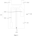
- each of the feeding baluns includes a first feeding component 210 for the coupling feed with the first group of dipoles and a second feeding component 200 for the coupling feed with the second group of dipoles, the first feeding component 210 and the second feeding component 220 being disposed to have an angle therebetween.
- the first feeding component 210 is utilized to perform feeding on the two radiation arms 110 of a group of dipoles
- the second feeding component 220 is utilized to perform feeding on the two radiation arms 110 of another group of dipoles, thus the transmission of energy can be achieved, and it can be ensured that the radiation unit 10 can radiate signals in a stable and reliable manner.
- the first feeding component 210 includes a first media 211, a first feeding member and two first grounding members.
- the first feeding member is disposed on one side of the first media 211 by means such as engaging or bonding
- the two first grounding members are disposed on the other side of the first media 211 by means such as engaging or bonding
- the two first grounding members are disposed to be spaced apart relative to each other.
- the first feeding member is coupled and connected with the two first grounding members, and the two first grounding members are connected with the two radiation arms 110 of the first group of dipoles in one-to-one correspondence.
- the first feeding member is coupled and connected with each of the two first grounding members, and the two first grounding members are connected with the two radiation arms 110 of the first group of dipoles in one-to-one correspondence, thus the first feed can be utilized to perform coupling feed on the first group of dipoles, so that the radiation unit meets good impedance characteristics.
- the first media 211 can be provided as a plate made of insulating materials.
- the first feeding member can be provided as a first balun microstrip line 212, as shown in Fig. 2 .
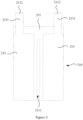
- the first balun microstrip line 212 includes a first branch 2121 and a second branch 2122 which are electrically connected, one end of the first branch 2121 is electrically connected with an external feed network, and the second branch 212 has one end hanging in the air, and the first branch 2121 and the second branch 2122 are respectively disposed in correspondence with the two first grounding members and coupled and connected with them. As shown in Fig.
- the first grounding member can be provided as a first microstrip ground piece 213, one end of the first microstrip ground piece 213 is electrically connected with a corresponding radiation arm 110 by means such as welding, and the other end of the first microstrip ground piece 213 is connected with ground base plate by means such as welding.
- the number of the first grounding members can be flexibly adjusted as required, as long as the coupling feed to the radiation arms 110 can be enabled.
- the second feeding component 220 includes a second media 221 disposed at an angle to the first media 211, a second feeding member and two second grounding members.
- the second feeding member is disposed on one side of the second media 221 by means such as engaging or bonding
- the second grounding member is disposed on the other side of the second media 221 by means such as engaging or bonding
- the two second grounding members are disposed to be spaced apart from each other.
- the second feeding member is coupled and connected with the two second grounding members, and the two second grounding members are connected with the two radiation arms 110 of second group of dipoles in one-to-one correspondence.
- the second feeding member is coupled and connected with each of the two second grounding members, and the two second grounding members are connected with the two radiation arms 110 of second group of dipoles in one-to-one correspondence, thus the second feeding member can be utilized to perform coupling feed on second group of dipoles, so that the radiation unit meets good impedance characteristics.
- second media 221 can be provided as a plate made of insulating materials.
- the second feeding member can be provided as a second balun microstrip line 222, as shown in Fig. 4 .
- the second balun microstrip line 222 includes a third branch 2221 and a fourth branch 2222 which are electrically connected, one end of the third branch 2221 is electrically connected with an external feed network, and the fourth branch 2222 has one end hanging in the air, and the third branch 2221 and the fourth branch 2222 are respectively disposed in correspondence with the two first grounding members and coupled and connected with them.
- the second feeding member can be provided as a second microstrip ground piece 223, one end of the second microstrip ground piece 223 is electrically connected with a corresponding radiation arm 110 by means such as welding, and the other end of the second microstrip ground piece 223 is connected with ground base plate by means such as welding.
- the number of the two grounding members can be flexibly adjusted as required, as long as the coupling feed to the radiation arms 110 can be enabled.
- the first media 211 and the second media 221 which are disposed to have an angle therebetween can be implemented by means of pluggable fitting, are easy for disassembly and assembly, and are of high assembling efficiency.
- the first media 211 is disposed perpendicular to the second media 221 in a compact layout.
- the first media 211 is provided with a first socket 2111
- the second media 221 is provided with a second socket 2211 which is disposed corresponding to the first socket 2111.
- the first media 211 is above the second media 221, so that the second socket 2211 corresponds to the first socket 2111, and then the second media 221 is inserted into the first socket 2111 until the first media 211 is inserted into the second socket 2211, and then the first media 211 and the second media 221 can be stably and reliably connected together to form a support structure for providing stable support for the radiation unit 10.
- the width of the first socket 2111 and the width of the second socket 2211 can be flexibly adjusted according to the thicknesses of the second media 221 and the first media 211.
- one end of the first grounding member is provided with a first bump 2131 for pluggable fitting with a respective radiation arm 110.
- one end of the second grounding member is provided with a second bump 2231 for pluggable fitting with a respective radiation arm 110.
- a corresponding feeding socket 1000 can be provided on a radiation arm 110 for plugging the first bump 2131 and the second bump 2231 into the feeding socket 1000, thus the electrical connection between the first grounding member and the second grounding member and the radiation arm 110 can be implement in a simple and convenient manner.
- the first media 211 may also be provided with a third bump 2112 which is disposed corresponding to the first bump 2131; as shown in Fig. 5 , the second media 221 may also be provided with a fourth bump 2212 which is disposed corresponding to the second bump 2231; thus the plugging strength of the first bump 2131 and the second bump 2231 are increased. Jacks corresponding to the feeding sockets 1000 also need to be opened on the substrate 300.
- the 5G antenna includes at least three radiation units 10 which are disposed to be equally spaced apart from each other in a preset distance.
- three radiation units 10 are utilized to constitute a subarray, and the spacing between two adjacent radiation units 10 is preferably 62.5 mm.
- four subarrays can constitute a 5G antenna array, and the spacing between adjacent subarrays is preferably 52 mm. Therefore, the sizes of the radiation units 10 can be adjusted according to actual frequency requirements to meet the different operating frequency requirements, and the radiation units 10 are used in combination to meet 5G antenna requirements, so that as compared with other array antennas, the pattern of the 5G array antenna are improved significantly and have good standing waves, as shown in Fig. 6 ; the beam widths in the horizontal plane all reach 60° or more, as shown in Fig. 7 .
Landscapes
- Engineering & Computer Science (AREA)
- Computer Networks & Wireless Communication (AREA)
- Variable-Direction Aerials And Aerial Arrays (AREA)
- Details Of Aerials (AREA)
Claims (6)
- Strahlungseinheit (10), umfassend:zwei Gruppen von Dipolen, deren Polarisationen orthogonal sind, wobei jede Gruppe der Dipole zwei Strahlungsarme (110) umfasst, die angeordnet sind, um relativ zueinander beabstandet zu sein, und jeder der Strahlungsarme (110) mit einem ersten Verlängerungszweig (120) und einem zweiten Verlängerungszweig (130) versehen ist, die angeordnet sind, um voneinander beabstandet zu sein;wobei die Fläche des ersten Verlängerungszweigs (120) größer ist als die Fläche des zweiten Verlängerungszweigs (130);wobei eine äußere Seitenwand jedes der Strahlungsarme (110) mit einer abgeschnittenen Ecke (190) versehen ist;wobei jeder der Strahlungsarme (110) mit einer ersten ausgehöhlten Nut (140) versehen ist, wobei jeweils ein Ende des ersten Verlängerungszweigs (120) und ein Ende des zweiten Verlängerungszweigs (130) mit der äußeren Seitenwand jedes der Strahlungsarme (110) verbunden ist, eine erste Abstandhalter-Nut (150), die mit der ersten ausgehöhlten Nut (140) kommuniziert, zwischen dem ersten Verlängerungszweig (120) und dem zweiten Verlängerungszweig (130) vorgesehen ist, und jeder des ersten Verlängerungszweigs (120) und des zweiten Verlängerungszweigs (130) zur Innenseite der ersten ausgehöhlten Nut (140) hin angeordnet ist;wobei zwischen den zwei benachbarten Strahlungsarmen (110) eine zweite Abstandhalter-Nut (160) und ein stromleitender Teil (180) zum Verbinden zweier benachbarter Strahlungsarme (110) vorgesehen sind, und jeder der zwei benachbarten Strahlungsarme (110) mit einer zweiten ausgehöhlten Nut (170) versehen ist, die mit der zweiten Abstandhalter-Nut (160) kommuniziert.
- Strahlungseinheit (10) nach Anspruch 1, wobei jeder der Strahlungsarme (110) mit einem ersten Kopplungsabschnitt zum Koppeln der Einspeisung mit einem Einspeisebalun versehen ist.
- Strahlungseinheit (10) nach Anspruch 1, wobei ein Abstand zwischen einer Seitenwand der ersten ausgehöhlten Nut (140) und einer Seitenwand der zweiten Abstandhalter-Nut (160) im Bereich von 5,5 mm bis 6 mm liegt; und eine Breite der zweiten ausgehöhlten Nut (170) im Bereich von 11,9 mm bis 12,7 mm liegt.
- 5-G-Antenne, umfassend:die Strahlungseinheit (10) nach einem der Ansprüche 1-3, undEinspeisebaluns, die mit den Strahlungsarmen (110) in Kopplungs-Einspeisung stehen.
- 5G-Antenne nach Anspruch 4, wobei die Strahlungseinheit (10) ferner ein Substrat (300) umfasst, das zwischen den Strahlungsarmen (110) und den Einspeisebaluns vorgesehen ist, und die Strahlungsarme (110) auf einer Oberfläche des Substrats (300) angeordnet sind.
- 5G-Antenne nach Anspruch 4 oder 5, wobei jeder der Einspeisebaluns eine erste Einspeisekomponente (210) für die Kopplungs-Einspeisung mit der ersten Gruppe von Dipolen und eine zweite Einspeisekomponente (220) für die Kopplungs-Einspeisung mit der zweiten Gruppe von Dipolen umfasst, wobei die erste Einspeisekomponente und die zweite Einspeisekomponente so angeordnet sind, dass sie einen Winkel dazwischen aufweisen.
Applications Claiming Priority (2)
| Application Number | Priority Date | Filing Date | Title |
|---|---|---|---|
| CN201911323563.3A CN111129750B (zh) | 2019-12-20 | 2019-12-20 | 5g天线及其辐射单元 |
| PCT/CN2020/110587 WO2021120663A1 (zh) | 2019-12-20 | 2020-08-21 | 5g天线及其辐射单元 |
Publications (4)
| Publication Number | Publication Date |
|---|---|
| EP4064453A1 EP4064453A1 (de) | 2022-09-28 |
| EP4064453A4 EP4064453A4 (de) | 2022-12-14 |
| EP4064453C0 EP4064453C0 (de) | 2025-05-21 |
| EP4064453B1 true EP4064453B1 (de) | 2025-05-21 |
Family
ID=70500486
Family Applications (1)
| Application Number | Title | Priority Date | Filing Date |
|---|---|---|---|
| EP20903178.0A Active EP4064453B1 (de) | 2019-12-20 | 2020-08-21 | 5g-antenne und strahlungseinheit dafür |
Country Status (3)
| Country | Link |
|---|---|
| EP (1) | EP4064453B1 (de) |
| CN (1) | CN111129750B (de) |
| WO (1) | WO2021120663A1 (de) |
Families Citing this family (4)
| Publication number | Priority date | Publication date | Assignee | Title |
|---|---|---|---|---|
| CN111129750B (zh) * | 2019-12-20 | 2022-07-12 | 京信通信技术(广州)有限公司 | 5g天线及其辐射单元 |
| WO2021248357A1 (zh) | 2020-06-10 | 2021-12-16 | 罗森伯格技术有限公司 | 一种5g天线单元及5g天线 |
| CN112768899B (zh) * | 2020-12-29 | 2023-03-21 | 京信通信技术(广州)有限公司 | 辐射单元及天线 |
| CN113690592B (zh) * | 2021-08-27 | 2023-03-14 | 普罗斯通信技术(苏州)有限公司 | 一种辐射元件以及天线 |
Family Cites Families (23)
| Publication number | Priority date | Publication date | Assignee | Title |
|---|---|---|---|---|
| AU730484B2 (en) * | 1997-07-03 | 2001-03-08 | Alcatel | Dual polarized cross bow tie antenna with airline feed |
| US7688271B2 (en) * | 2006-04-18 | 2010-03-30 | Andrew Llc | Dipole antenna |
| WO2010033865A2 (en) * | 2008-09-19 | 2010-03-25 | Rayspan Corporation | Metamaterial loaded antenna devices |
| CN101465475A (zh) * | 2009-01-12 | 2009-06-24 | 京信通信系统(中国)有限公司 | 双极化辐射单元及其平面振子 |
| US9620849B2 (en) * | 2013-06-03 | 2017-04-11 | Blackberry Limited | Coupled-feed wideband antenna |
| CN203631724U (zh) * | 2013-09-05 | 2014-06-04 | 广东博纬通信科技有限公司 | 一种双极化宽频天线振子单元以及宽频天线 |
| US10027030B2 (en) * | 2013-12-11 | 2018-07-17 | Nuvotronics, Inc | Dielectric-free metal-only dipole-coupled broadband radiating array aperture with wide field of view |
| CN103647140B (zh) * | 2013-12-16 | 2016-05-18 | 广州杰赛科技股份有限公司 | 双极化天线 |
| JP5872018B1 (ja) * | 2014-12-19 | 2016-03-01 | 電気興業株式会社 | 偏波共用アンテナ装置 |
| SG10201505215SA (en) * | 2015-06-30 | 2017-01-27 | Matsing Pte Ltd | Dual Polarized Radiator For Lens Antennas |
| CN204857972U (zh) * | 2015-08-11 | 2015-12-09 | 广东健博通科技股份有限公司 | 一种分形镂空设计超宽带双极化天线振子 |
| TWI619313B (zh) * | 2016-04-29 | 2018-03-21 | 和碩聯合科技股份有限公司 | 電子裝置及其雙頻印刷式天線 |
| CN107069197A (zh) * | 2017-01-11 | 2017-08-18 | 上海安费诺永亿通讯电子有限公司 | 一种十六分之一波长超低剖面双极化振子单元及基站天线 |
| CN107994322B (zh) * | 2017-11-10 | 2024-04-26 | 杭州睿达汽车科技有限公司 | 超宽频带双极化辐射单元 |
| CN207611860U (zh) * | 2017-11-10 | 2018-07-13 | 杭州睿达汽车科技有限公司 | 一种超宽频带双极化辐射单元 |
| CN209119327U (zh) * | 2018-11-06 | 2019-07-16 | 深圳市鑫龙通信技术有限公司 | 一种基站的天线振子 |
| CN109659677B (zh) * | 2018-12-28 | 2024-08-13 | 华南理工大学 | 天线及其辐射单元 |
| CN209730180U (zh) * | 2019-01-22 | 2019-12-03 | 西安箭达信息科技有限公司 | 一种高增益双极化偶极子对天线 |
| CN209516000U (zh) * | 2019-01-24 | 2019-10-18 | 江苏亨鑫科技有限公司 | 一种辐射单元及天线 |
| CN209730163U (zh) * | 2019-04-08 | 2019-12-03 | 广州杰赛科技股份有限公司 | 小型双极化天线辐射装置及通信设备 |
| CN110233343A (zh) * | 2019-07-02 | 2019-09-13 | 京信通信技术(广州)有限公司 | 双频双极化天线及辐射单元 |
| CN111129750B (zh) * | 2019-12-20 | 2022-07-12 | 京信通信技术(广州)有限公司 | 5g天线及其辐射单元 |
| CN210957003U (zh) * | 2019-12-20 | 2020-07-07 | 京信通信技术(广州)有限公司 | 5g天线及其辐射单元 |
-
2019
- 2019-12-20 CN CN201911323563.3A patent/CN111129750B/zh active Active
-
2020
- 2020-08-21 EP EP20903178.0A patent/EP4064453B1/de active Active
- 2020-08-21 WO PCT/CN2020/110587 patent/WO2021120663A1/zh not_active Ceased
Also Published As
| Publication number | Publication date |
|---|---|
| WO2021120663A1 (zh) | 2021-06-24 |
| EP4064453A1 (de) | 2022-09-28 |
| CN111129750A (zh) | 2020-05-08 |
| CN111129750B (zh) | 2022-07-12 |
| EP4064453C0 (de) | 2025-05-21 |
| EP4064453A4 (de) | 2022-12-14 |
Similar Documents
| Publication | Publication Date | Title |
|---|---|---|
| EP4064453B1 (de) | 5g-antenne und strahlungseinheit dafür | |
| CN109904613B (zh) | 一种应用于5G Sub 6GHz基站系统的差分双频双极化滤波天线 | |
| CN103682588B (zh) | 高增益和宽频带互补天线 | |
| CN101246997B (zh) | 宽带阵列天线的馈电网络 | |
| US20120169552A1 (en) | Hybrid multi-antenna system and wireless communication apparatus using the same | |
| CN109659674B (zh) | 一种通讯天线及其辐射单元 | |
| CN105186140B (zh) | 一种小型宽波束双极化微带天线 | |
| CN111656612A (zh) | 偶极天线 | |
| CN206850029U (zh) | 高频超宽带双极化全波辐射单元 | |
| US11264730B2 (en) | Quad-port radiating element | |
| CN108767481A (zh) | 一种宽波束的方向图可重构整流天线 | |
| WO2007099524A2 (en) | Ultra wide band flat antenna | |
| CN108155484B (zh) | 宽频带的双极化壁挂天线 | |
| CN109167163B (zh) | 超宽带双极化振子天线 | |
| KR20150052172A (ko) | 광대역 멀티-스트립 패치 안테나 | |
| US20190190165A1 (en) | High performance flat panel antennas for dual band, wide band and dual polarity operation | |
| US12456812B1 (en) | Single arm spiral antennas | |
| CN108134197A (zh) | 一体化四点差分馈电低剖面双极化振子单元及基站天线 | |
| US7050014B1 (en) | Low profile horizontally polarized sector dipole antenna | |
| CN114300835B (zh) | 一种适用于基站的宽频带双极化滤波天线 | |
| CN210957003U (zh) | 5g天线及其辐射单元 | |
| CN107799888B (zh) | 一种双频高增益贴片天线 | |
| US20200266545A1 (en) | Broad band dipole antenna | |
| CN109755738A (zh) | 一种双极化网格天线 | |
| CN104993245A (zh) | S波段动中通双频圆极化微带天线及其阵列 |
Legal Events
| Date | Code | Title | Description |
|---|---|---|---|
| STAA | Information on the status of an ep patent application or granted ep patent |
Free format text: STATUS: THE INTERNATIONAL PUBLICATION HAS BEEN MADE |
|
| PUAI | Public reference made under article 153(3) epc to a published international application that has entered the european phase |
Free format text: ORIGINAL CODE: 0009012 |
|
| STAA | Information on the status of an ep patent application or granted ep patent |
Free format text: STATUS: REQUEST FOR EXAMINATION WAS MADE |
|
| 17P | Request for examination filed |
Effective date: 20220623 |
|
| AK | Designated contracting states |
Kind code of ref document: A1 Designated state(s): AL AT BE BG CH CY CZ DE DK EE ES FI FR GB GR HR HU IE IS IT LI LT LU LV MC MK MT NL NO PL PT RO RS SE SI SK SM TR |
|
| REG | Reference to a national code |
Ref country code: DE Free format text: PREVIOUS MAIN CLASS: H01Q0001380000 Ref country code: DE Ref legal event code: R079 Ref document number: 602020051865 Country of ref document: DE Free format text: PREVIOUS MAIN CLASS: H01Q0001380000 Ipc: H01Q0021240000 |
|
| A4 | Supplementary search report drawn up and despatched |
Effective date: 20221116 |
|
| RIC1 | Information provided on ipc code assigned before grant |
Ipc: H01Q 9/28 20060101ALI20221110BHEP Ipc: H01Q 1/24 20060101ALI20221110BHEP Ipc: H01Q 25/00 20060101ALI20221110BHEP Ipc: H01Q 21/26 20060101ALI20221110BHEP Ipc: H01Q 21/24 20060101AFI20221110BHEP |
|
| DAV | Request for validation of the european patent (deleted) | ||
| DAX | Request for extension of the european patent (deleted) | ||
| P01 | Opt-out of the competence of the unified patent court (upc) registered |
Effective date: 20230517 |
|
| GRAP | Despatch of communication of intention to grant a patent |
Free format text: ORIGINAL CODE: EPIDOSNIGR1 |
|
| STAA | Information on the status of an ep patent application or granted ep patent |
Free format text: STATUS: GRANT OF PATENT IS INTENDED |
|
| INTG | Intention to grant announced |
Effective date: 20250207 |
|
| GRAS | Grant fee paid |
Free format text: ORIGINAL CODE: EPIDOSNIGR3 |
|
| GRAA | (expected) grant |
Free format text: ORIGINAL CODE: 0009210 |
|
| STAA | Information on the status of an ep patent application or granted ep patent |
Free format text: STATUS: THE PATENT HAS BEEN GRANTED |
|
| AK | Designated contracting states |
Kind code of ref document: B1 Designated state(s): AL AT BE BG CH CY CZ DE DK EE ES FI FR GB GR HR HU IE IS IT LI LT LU LV MC MK MT NL NO PL PT RO RS SE SI SK SM TR |
|
| REG | Reference to a national code |
Ref country code: GB Ref legal event code: FG4D |
|
| REG | Reference to a national code |
Ref country code: CH Ref legal event code: EP |
|
| REG | Reference to a national code |
Ref country code: DE Ref legal event code: R096 Ref document number: 602020051865 Country of ref document: DE |
|
| REG | Reference to a national code |
Ref country code: IE Ref legal event code: FG4D |
|
| U01 | Request for unitary effect filed |
Effective date: 20250619 |
|
| U07 | Unitary effect registered |
Designated state(s): AT BE BG DE DK EE FI FR IT LT LU LV MT NL PT RO SE SI Effective date: 20250630 |
|
| P04 | Withdrawal of opt-out of the competence of the unified patent court (upc) registered |
Free format text: CASE NUMBER: APP_30559/2025 Effective date: 20250625 |
|
| U20 | Renewal fee for the european patent with unitary effect paid |
Year of fee payment: 6 Effective date: 20250827 |
|
| PG25 | Lapsed in a contracting state [announced via postgrant information from national office to epo] |
Ref country code: ES Free format text: LAPSE BECAUSE OF FAILURE TO SUBMIT A TRANSLATION OF THE DESCRIPTION OR TO PAY THE FEE WITHIN THE PRESCRIBED TIME-LIMIT Effective date: 20250521 |
|
| PG25 | Lapsed in a contracting state [announced via postgrant information from national office to epo] |
Ref country code: NO Free format text: LAPSE BECAUSE OF FAILURE TO SUBMIT A TRANSLATION OF THE DESCRIPTION OR TO PAY THE FEE WITHIN THE PRESCRIBED TIME-LIMIT Effective date: 20250821 Ref country code: GR Free format text: LAPSE BECAUSE OF FAILURE TO SUBMIT A TRANSLATION OF THE DESCRIPTION OR TO PAY THE FEE WITHIN THE PRESCRIBED TIME-LIMIT Effective date: 20250822 |
|
| PG25 | Lapsed in a contracting state [announced via postgrant information from national office to epo] |
Ref country code: PL Free format text: LAPSE BECAUSE OF FAILURE TO SUBMIT A TRANSLATION OF THE DESCRIPTION OR TO PAY THE FEE WITHIN THE PRESCRIBED TIME-LIMIT Effective date: 20250521 |
|
| PG25 | Lapsed in a contracting state [announced via postgrant information from national office to epo] |
Ref country code: HR Free format text: LAPSE BECAUSE OF FAILURE TO SUBMIT A TRANSLATION OF THE DESCRIPTION OR TO PAY THE FEE WITHIN THE PRESCRIBED TIME-LIMIT Effective date: 20250521 |
|
| PG25 | Lapsed in a contracting state [announced via postgrant information from national office to epo] |
Ref country code: RS Free format text: LAPSE BECAUSE OF FAILURE TO SUBMIT A TRANSLATION OF THE DESCRIPTION OR TO PAY THE FEE WITHIN THE PRESCRIBED TIME-LIMIT Effective date: 20250821 |
|
| PG25 | Lapsed in a contracting state [announced via postgrant information from national office to epo] |
Ref country code: IS Free format text: LAPSE BECAUSE OF FAILURE TO SUBMIT A TRANSLATION OF THE DESCRIPTION OR TO PAY THE FEE WITHIN THE PRESCRIBED TIME-LIMIT Effective date: 20250921 |
|
| PG25 | Lapsed in a contracting state [announced via postgrant information from national office to epo] |
Ref country code: SM Free format text: LAPSE BECAUSE OF FAILURE TO SUBMIT A TRANSLATION OF THE DESCRIPTION OR TO PAY THE FEE WITHIN THE PRESCRIBED TIME-LIMIT Effective date: 20250521 |
|
| PG25 | Lapsed in a contracting state [announced via postgrant information from national office to epo] |
Ref country code: CZ Free format text: LAPSE BECAUSE OF FAILURE TO SUBMIT A TRANSLATION OF THE DESCRIPTION OR TO PAY THE FEE WITHIN THE PRESCRIBED TIME-LIMIT Effective date: 20250521 |
|
| PG25 | Lapsed in a contracting state [announced via postgrant information from national office to epo] |
Ref country code: SK Free format text: LAPSE BECAUSE OF FAILURE TO SUBMIT A TRANSLATION OF THE DESCRIPTION OR TO PAY THE FEE WITHIN THE PRESCRIBED TIME-LIMIT Effective date: 20250521 |