EP4064409A1 - Battery, electric apparatus, and method and device for preparing battery - Google Patents
Battery, electric apparatus, and method and device for preparing battery Download PDFInfo
- Publication number
- EP4064409A1 EP4064409A1 EP20957980.4A EP20957980A EP4064409A1 EP 4064409 A1 EP4064409 A1 EP 4064409A1 EP 20957980 A EP20957980 A EP 20957980A EP 4064409 A1 EP4064409 A1 EP 4064409A1
- Authority
- EP
- European Patent Office
- Prior art keywords
- fastener
- fire prevention
- battery
- battery cell
- prevention pipeline
- Prior art date
- Legal status (The legal status is an assumption and is not a legal conclusion. Google has not performed a legal analysis and makes no representation as to the accuracy of the status listed.)
- Pending
Links
- 238000000034 method Methods 0.000 title claims abstract description 16
- 230000002265 prevention Effects 0.000 claims description 185
- 230000007246 mechanism Effects 0.000 claims description 60
- 238000000926 separation method Methods 0.000 claims description 22
- 238000009434 installation Methods 0.000 claims description 17
- 238000006073 displacement reaction Methods 0.000 claims description 8
- 239000003292 glue Substances 0.000 claims description 3
- 238000010586 diagram Methods 0.000 description 17
- 239000007789 gas Substances 0.000 description 7
- 238000001816 cooling Methods 0.000 description 6
- 239000011248 coating agent Substances 0.000 description 5
- 238000000576 coating method Methods 0.000 description 5
- 230000005611 electricity Effects 0.000 description 5
- 239000003792 electrolyte Substances 0.000 description 5
- 238000005516 engineering process Methods 0.000 description 5
- 239000000463 material Substances 0.000 description 4
- VNWKTOKETHGBQD-UHFFFAOYSA-N methane Chemical compound C VNWKTOKETHGBQD-UHFFFAOYSA-N 0.000 description 4
- 230000008569 process Effects 0.000 description 4
- LYCAIKOWRPUZTN-UHFFFAOYSA-N Ethylene glycol Chemical compound OCCO LYCAIKOWRPUZTN-UHFFFAOYSA-N 0.000 description 3
- 230000009471 action Effects 0.000 description 3
- 230000000712 assembly Effects 0.000 description 3
- 238000000429 assembly Methods 0.000 description 3
- 238000004880 explosion Methods 0.000 description 3
- 239000012530 fluid Substances 0.000 description 3
- 239000000203 mixture Substances 0.000 description 3
- 239000000243 solution Substances 0.000 description 3
- 239000003351 stiffener Substances 0.000 description 3
- 239000000126 substance Substances 0.000 description 3
- XLYOFNOQVPJJNP-UHFFFAOYSA-N water Substances O XLYOFNOQVPJJNP-UHFFFAOYSA-N 0.000 description 3
- 238000003466 welding Methods 0.000 description 3
- HBBGRARXTFLTSG-UHFFFAOYSA-N Lithium ion Chemical compound [Li+] HBBGRARXTFLTSG-UHFFFAOYSA-N 0.000 description 2
- 239000013543 active substance Substances 0.000 description 2
- 230000008859 change Effects 0.000 description 2
- 238000006243 chemical reaction Methods 0.000 description 2
- 238000002485 combustion reaction Methods 0.000 description 2
- 238000004891 communication Methods 0.000 description 2
- 239000002826 coolant Substances 0.000 description 2
- 239000012809 cooling fluid Substances 0.000 description 2
- 238000013461 design Methods 0.000 description 2
- 238000004090 dissolution Methods 0.000 description 2
- 230000000694 effects Effects 0.000 description 2
- 239000012634 fragment Substances 0.000 description 2
- 238000002347 injection Methods 0.000 description 2
- 239000007924 injection Substances 0.000 description 2
- 239000012774 insulation material Substances 0.000 description 2
- 239000007788 liquid Substances 0.000 description 2
- 229910001416 lithium ion Inorganic materials 0.000 description 2
- 238000012986 modification Methods 0.000 description 2
- 230000004048 modification Effects 0.000 description 2
- 239000003345 natural gas Substances 0.000 description 2
- 239000004033 plastic Substances 0.000 description 2
- 230000002269 spontaneous effect Effects 0.000 description 2
- DGAQECJNVWCQMB-PUAWFVPOSA-M Ilexoside XXIX Chemical compound C[C@@H]1CC[C@@]2(CC[C@@]3(C(=CC[C@H]4[C@]3(CC[C@@H]5[C@@]4(CC[C@@H](C5(C)C)OS(=O)(=O)[O-])C)C)[C@@H]2[C@]1(C)O)C)C(=O)O[C@H]6[C@@H]([C@H]([C@@H]([C@H](O6)CO)O)O)O.[Na+] DGAQECJNVWCQMB-PUAWFVPOSA-M 0.000 description 1
- WHXSMMKQMYFTQS-UHFFFAOYSA-N Lithium Chemical group [Li] WHXSMMKQMYFTQS-UHFFFAOYSA-N 0.000 description 1
- JLVVSXFLKOJNIY-UHFFFAOYSA-N Magnesium ion Chemical compound [Mg+2] JLVVSXFLKOJNIY-UHFFFAOYSA-N 0.000 description 1
- JDZCKJOXGCMJGS-UHFFFAOYSA-N [Li].[S] Chemical compound [Li].[S] JDZCKJOXGCMJGS-UHFFFAOYSA-N 0.000 description 1
- 239000000853 adhesive Substances 0.000 description 1
- 230000001070 adhesive effect Effects 0.000 description 1
- 239000003570 air Substances 0.000 description 1
- 238000013459 approach Methods 0.000 description 1
- 238000010276 construction Methods 0.000 description 1
- 239000000112 cooling gas Substances 0.000 description 1
- 238000005336 cracking Methods 0.000 description 1
- 230000001066 destructive effect Effects 0.000 description 1
- 238000009792 diffusion process Methods 0.000 description 1
- 239000002803 fossil fuel Substances 0.000 description 1
- 239000002737 fuel gas Substances 0.000 description 1
- 230000014509 gene expression Effects 0.000 description 1
- 238000010438 heat treatment Methods 0.000 description 1
- 238000001746 injection moulding Methods 0.000 description 1
- 238000011900 installation process Methods 0.000 description 1
- 238000009413 insulation Methods 0.000 description 1
- 239000012212 insulator Substances 0.000 description 1
- 229910052744 lithium Inorganic materials 0.000 description 1
- 230000007774 longterm Effects 0.000 description 1
- 229910001425 magnesium ion Inorganic materials 0.000 description 1
- 239000010445 mica Substances 0.000 description 1
- 229910052618 mica group Inorganic materials 0.000 description 1
- 238000012545 processing Methods 0.000 description 1
- 230000001105 regulatory effect Effects 0.000 description 1
- 238000011160 research Methods 0.000 description 1
- 229910052708 sodium Inorganic materials 0.000 description 1
- 239000011734 sodium Substances 0.000 description 1
- 238000004804 winding Methods 0.000 description 1
Images



Classifications
-
- H—ELECTRICITY
- H01—ELECTRIC ELEMENTS
- H01M—PROCESSES OR MEANS, e.g. BATTERIES, FOR THE DIRECT CONVERSION OF CHEMICAL ENERGY INTO ELECTRICAL ENERGY
- H01M50/00—Constructional details or processes of manufacture of the non-active parts of electrochemical cells other than fuel cells, e.g. hybrid cells
- H01M50/30—Arrangements for facilitating escape of gases
- H01M50/383—Flame arresting or ignition-preventing means
-
- H—ELECTRICITY
- H01—ELECTRIC ELEMENTS
- H01M—PROCESSES OR MEANS, e.g. BATTERIES, FOR THE DIRECT CONVERSION OF CHEMICAL ENERGY INTO ELECTRICAL ENERGY
- H01M10/00—Secondary cells; Manufacture thereof
- H01M10/42—Methods or arrangements for servicing or maintenance of secondary cells or secondary half-cells
-
- A—HUMAN NECESSITIES
- A62—LIFE-SAVING; FIRE-FIGHTING
- A62C—FIRE-FIGHTING
- A62C3/00—Fire prevention, containment or extinguishing specially adapted for particular objects or places
- A62C3/16—Fire prevention, containment or extinguishing specially adapted for particular objects or places in electrical installations, e.g. cableways
-
- A—HUMAN NECESSITIES
- A62—LIFE-SAVING; FIRE-FIGHTING
- A62C—FIRE-FIGHTING
- A62C35/00—Permanently-installed equipment
- A62C35/58—Pipe-line systems
- A62C35/68—Details, e.g. of pipes or valve systems
-
- H—ELECTRICITY
- H01—ELECTRIC ELEMENTS
- H01M—PROCESSES OR MEANS, e.g. BATTERIES, FOR THE DIRECT CONVERSION OF CHEMICAL ENERGY INTO ELECTRICAL ENERGY
- H01M10/00—Secondary cells; Manufacture thereof
- H01M10/60—Heating or cooling; Temperature control
- H01M10/65—Means for temperature control structurally associated with the cells
- H01M10/656—Means for temperature control structurally associated with the cells characterised by the type of heat-exchange fluid
- H01M10/6567—Liquids
- H01M10/6568—Liquids characterised by flow circuits, e.g. loops, located externally to the cells or cell casings
-
- H—ELECTRICITY
- H01—ELECTRIC ELEMENTS
- H01M—PROCESSES OR MEANS, e.g. BATTERIES, FOR THE DIRECT CONVERSION OF CHEMICAL ENERGY INTO ELECTRICAL ENERGY
- H01M50/00—Constructional details or processes of manufacture of the non-active parts of electrochemical cells other than fuel cells, e.g. hybrid cells
- H01M50/20—Mountings; Secondary casings or frames; Racks, modules or packs; Suspension devices; Shock absorbers; Transport or carrying devices; Holders
- H01M50/262—Mountings; Secondary casings or frames; Racks, modules or packs; Suspension devices; Shock absorbers; Transport or carrying devices; Holders with fastening means, e.g. locks
-
- H—ELECTRICITY
- H01—ELECTRIC ELEMENTS
- H01M—PROCESSES OR MEANS, e.g. BATTERIES, FOR THE DIRECT CONVERSION OF CHEMICAL ENERGY INTO ELECTRICAL ENERGY
- H01M50/00—Constructional details or processes of manufacture of the non-active parts of electrochemical cells other than fuel cells, e.g. hybrid cells
- H01M50/30—Arrangements for facilitating escape of gases
-
- H—ELECTRICITY
- H01—ELECTRIC ELEMENTS
- H01M—PROCESSES OR MEANS, e.g. BATTERIES, FOR THE DIRECT CONVERSION OF CHEMICAL ENERGY INTO ELECTRICAL ENERGY
- H01M50/00—Constructional details or processes of manufacture of the non-active parts of electrochemical cells other than fuel cells, e.g. hybrid cells
- H01M50/30—Arrangements for facilitating escape of gases
- H01M50/342—Non-re-sealable arrangements
- H01M50/3425—Non-re-sealable arrangements in the form of rupturable membranes or weakened parts, e.g. pierced with the aid of a sharp member
-
- H—ELECTRICITY
- H01—ELECTRIC ELEMENTS
- H01M—PROCESSES OR MEANS, e.g. BATTERIES, FOR THE DIRECT CONVERSION OF CHEMICAL ENERGY INTO ELECTRICAL ENERGY
- H01M50/00—Constructional details or processes of manufacture of the non-active parts of electrochemical cells other than fuel cells, e.g. hybrid cells
- H01M50/30—Arrangements for facilitating escape of gases
- H01M50/375—Vent means sensitive to or responsive to temperature
-
- H—ELECTRICITY
- H01—ELECTRIC ELEMENTS
- H01M—PROCESSES OR MEANS, e.g. BATTERIES, FOR THE DIRECT CONVERSION OF CHEMICAL ENERGY INTO ELECTRICAL ENERGY
- H01M50/00—Constructional details or processes of manufacture of the non-active parts of electrochemical cells other than fuel cells, e.g. hybrid cells
- H01M50/50—Current conducting connections for cells or batteries
- H01M50/502—Interconnectors for connecting terminals of adjacent batteries; Interconnectors for connecting cells outside a battery casing
-
- H—ELECTRICITY
- H01—ELECTRIC ELEMENTS
- H01M—PROCESSES OR MEANS, e.g. BATTERIES, FOR THE DIRECT CONVERSION OF CHEMICAL ENERGY INTO ELECTRICAL ENERGY
- H01M50/00—Constructional details or processes of manufacture of the non-active parts of electrochemical cells other than fuel cells, e.g. hybrid cells
- H01M50/50—Current conducting connections for cells or batteries
- H01M50/543—Terminals
-
- H—ELECTRICITY
- H01—ELECTRIC ELEMENTS
- H01M—PROCESSES OR MEANS, e.g. BATTERIES, FOR THE DIRECT CONVERSION OF CHEMICAL ENERGY INTO ELECTRICAL ENERGY
- H01M10/00—Secondary cells; Manufacture thereof
- H01M10/60—Heating or cooling; Temperature control
- H01M10/61—Types of temperature control
- H01M10/613—Cooling or keeping cold
-
- H—ELECTRICITY
- H01—ELECTRIC ELEMENTS
- H01M—PROCESSES OR MEANS, e.g. BATTERIES, FOR THE DIRECT CONVERSION OF CHEMICAL ENERGY INTO ELECTRICAL ENERGY
- H01M10/00—Secondary cells; Manufacture thereof
- H01M10/60—Heating or cooling; Temperature control
- H01M10/65—Means for temperature control structurally associated with the cells
- H01M10/655—Solid structures for heat exchange or heat conduction
- H01M10/6556—Solid parts with flow channel passages or pipes for heat exchange
-
- H—ELECTRICITY
- H01—ELECTRIC ELEMENTS
- H01M—PROCESSES OR MEANS, e.g. BATTERIES, FOR THE DIRECT CONVERSION OF CHEMICAL ENERGY INTO ELECTRICAL ENERGY
- H01M2200/00—Safety devices for primary or secondary batteries
-
- H—ELECTRICITY
- H01—ELECTRIC ELEMENTS
- H01M—PROCESSES OR MEANS, e.g. BATTERIES, FOR THE DIRECT CONVERSION OF CHEMICAL ENERGY INTO ELECTRICAL ENERGY
- H01M50/00—Constructional details or processes of manufacture of the non-active parts of electrochemical cells other than fuel cells, e.g. hybrid cells
- H01M50/60—Arrangements or processes for filling or topping-up with liquids; Arrangements or processes for draining liquids from casings
- H01M50/673—Containers for storing liquids; Delivery conduits therefor
-
- Y—GENERAL TAGGING OF NEW TECHNOLOGICAL DEVELOPMENTS; GENERAL TAGGING OF CROSS-SECTIONAL TECHNOLOGIES SPANNING OVER SEVERAL SECTIONS OF THE IPC; TECHNICAL SUBJECTS COVERED BY FORMER USPC CROSS-REFERENCE ART COLLECTIONS [XRACs] AND DIGESTS
- Y02—TECHNOLOGIES OR APPLICATIONS FOR MITIGATION OR ADAPTATION AGAINST CLIMATE CHANGE
- Y02E—REDUCTION OF GREENHOUSE GAS [GHG] EMISSIONS, RELATED TO ENERGY GENERATION, TRANSMISSION OR DISTRIBUTION
- Y02E60/00—Enabling technologies; Technologies with a potential or indirect contribution to GHG emissions mitigation
- Y02E60/10—Energy storage using batteries
-
- Y—GENERAL TAGGING OF NEW TECHNOLOGICAL DEVELOPMENTS; GENERAL TAGGING OF CROSS-SECTIONAL TECHNOLOGIES SPANNING OVER SEVERAL SECTIONS OF THE IPC; TECHNICAL SUBJECTS COVERED BY FORMER USPC CROSS-REFERENCE ART COLLECTIONS [XRACs] AND DIGESTS
- Y02—TECHNOLOGIES OR APPLICATIONS FOR MITIGATION OR ADAPTATION AGAINST CLIMATE CHANGE
- Y02P—CLIMATE CHANGE MITIGATION TECHNOLOGIES IN THE PRODUCTION OR PROCESSING OF GOODS
- Y02P70/00—Climate change mitigation technologies in the production process for final industrial or consumer products
- Y02P70/50—Manufacturing or production processes characterised by the final manufactured product
Definitions
- This application relates to the field of battery technologies, and in particular, to a battery, an electric apparatus, and a method and a device for preparing battery.
- lithium-ion batteries and the like Due to the advantages of high energy density, high power density, a large number of charge and discharge cycles, and long storage time, lithium-ion batteries and the like have been widely used in electric vehicles.
- This application provides a battery, an electric apparatus, and a method and a device for preparing battery, to fasten a fire prevention pipeline to the battery and implement timely fire prevention on a battery cell in thermal runaway to ensure the safe use of the battery.
- a first aspect of this application provides a battery, including:
- the fastener includes an accommodating portion, the accommodating portion is configured to accommodate the electrode terminal, and the accommodating portion abuts against the electrode terminal, to limit displacement of the fastener.
- the accommodating portion is constructed to have an opening, so that at least part of the electrode terminal is exposed through the opening.
- the accommodating portion is a through hole that runs through the fastener.
- the fastener further includes a first convex portion, the first convex portion is provided around the periphery of the accommodating portion, and the first convex portion protrudes from the electrode terminal in a direction leaving the battery cell.
- the battery further includes a second convex portion that is provided between the fastener and the battery cell, and elastically abuts against the battery cell, to allow an assembly error between the fastener and the battery cell.
- the second convex portion is provided on the fastener and protrudes from a surface of the fastener closer to the battery cell.
- the second convex portion is elastic.
- the fastener further includes an accommodating hole that runs through the fastener.
- the second convex portion includes a fixed portion and a protruding portion that are connected, where one end of the fixed portion is configured to connect to the protruding portion, and the other end of the fixed portion is configured to connect to part of hole walls of the accommodating hole.
- a gap is present between the protruding portion and other hole walls of the accommodating hole, and the protruding portion protrudes from the surface of the fastener closer to the battery cell.
- a plurality of second convex portions are provided, and the plurality of second convex portions are arranged in such positions that the fastener and the battery cell are subject to balanced forces when the fastener abuts against the battery cell.
- the battery cell further includes a pressure relief mechanism, and the pressure relief mechanism is configured to be actuated when internal pressure or temperature of the battery cell reaches a threshold, to release the internal pressure;
- the first weak zone is provided as a through hole; or the first weak zone is configured to be destroyed to form a through hole when the pressure relief mechanism is actuated.
- a projected area of the fire prevention pipeline on the pressure relief mechanism is smaller than an area of the pressure relief mechanism.
- the fastener further includes a buckle.
- the buckle is configured to fasten the fire prevention pipeline to the fastener, and the buckle is provided on two sides of the first weak zone along a central axis of the fire prevention pipeline.
- the fastener further includes a first depression, configured to accommodate at least part of the fire prevention pipeline, and the first weak zone and the buckle are both provided in the first depression.
- the battery further includes a separation part, configured for installing a busbar.
- the busbar is connected to the electrode terminal, and the fastener is located between the separation part and the battery cell, to limit displacement of the fastener.
- the separation part includes a second weak zone, configured to allow emissions from the battery cell to pass through the second weak zone and destroy the fire prevention pipeline when the pressure relief mechanism is actuated.
- the fire prevention pipeline is bonded to the separation part.
- a protection part is further included, configured to connect to the separation part; the protection part includes a third weak zone, and the third weak zone is configured to allow the emissions from the battery cell to pass through the third weak zone and destroy the fire prevention pipeline when the pressure relief mechanism is actuated.
- the fire prevention pipeline is bonded to the protection part.
- positions at which glue is applied bypasses the third weak zone when the fire prevention pipeline is being bonded to the protection part.
- an electric apparatus including the battery described above, where the battery is configured to supply electrical energy.
- a method for preparing battery including the following steps:
- a device for preparing battery including:
- the fastener is provided to fasten the fire prevention pipeline to the electrode terminal reliably, so that the fire prevention pipeline can implement timely fire prevention on the battery cell, to ensure the safe use of the battery.
- plural means more than two (including two).
- a plurality of groups means more than two groups (including two groups).
- connection should be understood broadly.
- “connected” or “connection” of a mechanical structure may indicate physical connection.
- the physical connection may be fixed connection, for example, fixed connection by using a fastener such as a screw, a bolt or other fasteners; or the physical connection may be detachable connection, for example, connection by mutual clamping or clamping; or the physical connection may be an integral connection, for example, connection by welding, bonding or integral forming.
- Connected or “connection” of a circuit structure may indicate physical connection, and may also indicate electrical connection or signal connection, for example, may be direct connection, that is, the physical connection, may be indirect connection by using at least one element in between as long as circuit communication is implemented, and may also be communication between two elements; and the signal connection may be signal connection by using a circuit, and may also be signal connection by using a media medium, such as a radio wave.
- a media medium such as a radio wave
- the coordinate system in FIG. 1-D defines the directions of the battery.
- the direction x represents a length direction of the battery cell 400
- the direction y is perpendicular to the direction x in a horizontal plane, and represents a width direction of the battery cell 400
- the direction z is perpendicular to the direction x and the direction y, and represents a height direction of the battery.
- the foregoing expressions such as directions x, y and z that are used to describe indicated directions of operations and constructions of various members of the battery in the embodiments are relative rather than absolute. Although these indications are appropriate when the members of the battery are located at the positions shown in the drawings, these directions shall be interpreted differently when the positions change, to reflect the changes.
- a rechargeable battery may be referred to as a secondary battery or a traction battery.
- the most widely used rechargeable battery is lithium battery, for example, a lithium-sulfur battery, a sodium lithium-ion battery, or a magnesium-ion battery, which is not limited.
- rechargeable batteries may be collectively referred to as batteries in this specification.
- Safety of a battery is an important characteristic for measuring battery performance. It is necessary to ensure the safety of the battery as much as possible when using or charging.
- the battery typically includes a plurality of battery cells that are connected.
- a battery cell experiences an external short circuit, overcharge, needle puncture, plate impact, and the like, the battery cell is prone to thermal runaway.
- emissions will be generated inside the battery cell, including but not limited to electrolyte, fragments of positive and negative electrode plates and separator because of dissolution or breaking, high-temperature and high-pressure gas and flames generated by reactions, and the like. These emissions may have thermal diffusion in the process of emission, resulting in thermal runaway of other battery cells, and even explosion and other accidents.
- an existing effective solution is to provide a fire prevention pipeline.
- a fire prevention pipeline is used to prevent or delay explosion or fire of the battery cell.
- the fire prevention pipeline is typically provided in the box body.
- the fire prevention pipeline releases a fire prevention medium to implement fire prevention.
- the inventors have found that although the fire prevention pipeline is provided, a battery using the fire prevention pipeline mentioned above still cannot implement timely fire prevention in the case of thermal runaway of the battery.
- the inventors have tried to change the position of the fire prevention pipeline and the fire prevention manner, but none of them can solve the foregoing problem.
- the inventors have further discovered that the battery provided with the fire prevention pipeline still had a safety risk because the fire prevention pipeline was displaced in the process of thermal runaway of the battery, so that the fire prevention pipeline was unable to implement timely fire prevention on the part that experiences thermal runaway. In other words, the fire prevention pipeline was not fastened reliably.
- this application is intended to provide a battery, where an electrode terminal is connected to a fastener, to fasten the fastener to a battery cell, and a fire prevention pipeline is fastened by using the fastener.
- the problem of untimely fire prevention caused by displacement of the fire prevention pipeline in the process of thermal runaway of the battery in the prior art may be overcome.
- the battery in the embodiments of this application may be applied to various electric apparatuses that use electrical energy as power.
- the electric apparatuses herein may be, but are not limited to, electric cars, electric trains, electric bicycles, golf carts, drones, ships, and the like.
- the electric apparatuses may be apparatuses that use only batteries to supply power, or may be hybrid electric apparatuses.
- the battery supplies electrical energy to the electric apparatus, and the electric apparatus is driven by a motor.
- FIG. 1-A is a schematic structural diagram of an electric apparatus according to an embodiment of the application, where the electric apparatus may be a vehicle.
- the vehicle may be a fossil fuel vehicle, a natural gas vehicle, or a new energy vehicle.
- the new energy vehicle may be a battery electric vehicle, a hybrid electric vehicle, a range-extended vehicle, or the like.
- the vehicle includes a battery 200, a controller 210, and a motor 220.
- the battery 200 is configured to supply electricity to the controller 210 and the motor 220 as an operating power source and a driving power source of the vehicle.
- the battery 200 is configured to satisfy the need for electricity during start, navigation, and operation of the vehicle.
- the battery 200 supplies electricity to the controller 210, and the controller 210 controls the battery 200 to supply electricity to the motor 220.
- the motor 220 receives and uses the electricity from the battery 200 as a driving power source of the vehicle, to replace or partially replace fuel or natural gas as a driving power of the vehicle.
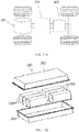
- the battery 200 may include a plurality of battery modules that are connected to each other. As shown in FIG. 1-B , the battery 200 includes a first housing 201, a second housing 202, and a plurality of battery modules 300, where the first housing 201 and the second housing 202 are buckled to each other, and a plurality of battery modules 300 are arranged in a space enclosed by the first housing 201 and the second housing 202.
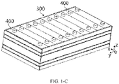
- a battery module 300 includes a plurality of battery cells 400, and the plurality of battery cells 400 may be connected in series, in parallel, or in hybrid connection mode to achieve a larger current or voltage.
- the hybrid connection means a combination of series connection and parallel connection. For example, as shown in FIG.
- the battery cell 400 may be placed upright, a height direction of the battery cell 400 is consistent with the vertical direction, and a plurality of battery cells 400 are arranged side by side in a width direction; or the battery cell 400 may be placed flat, the width direction of the battery cell 400 is consistent with the vertical direction, a plurality of battery cells 400 may be stacked in at least one layer in the width direction, and each layer includes a plurality of battery cells 400 that are arranged and spaced apart in a length direction.
- the battery cell 400 includes a housing 40, an electrode assembly 30, and an end cover assembly 10.
- the end cover assembly 10 includes an end cover plate 10', and the end cover plate 10' is connected to the housing 40 (for example, by welding), to form an enclosure of the battery cell 400.
- the electrode assembly 30 is provided in the housing 40, and the housing 40 is filled with electrolyte.
- the battery cell 400 may be cube-shaped, cuboid-shaped or cylinder-shaped.
- one or more electrode assemblies 30 may be configured. As shown in FIG. 1-D , at least two separate wound electrode assemblies 30 may alternatively be provided in the battery.
- a main body portion of the electrode assembly 30 may be formed by stacking or winding a first electrode plate, a second electrode plate, and a separator located between the first electrode plate and the second electrode plate that are arranged adjacently, where the separator is an insulator sandwiched between the first electrode plate and the second electrode plate.
- the main body portion has two opposite end surfaces.
- the first electrode plate is a positive electrode plate and the second electrode plate is a negative electrode plate.
- a positive electrode active substance is coated on a coating zone of the positive electrode plate, and the negative electrode active substance is coated on the coating zone of the negative electrode plate.
- a plurality of uncoated zones extending from a coating zone of the main body portion are stacked as tabs.
- the electrode assembly includes two tabs 301: a positive tab and a negative tab. The positive tab extends from a coating zone of the positive electrode plate, and the negative tab extends from a coating zone of the negative electrode plate.
- the end cover assembly 10 is provided on the top of the electrode assembly 30. As shown in FIG 1-D , the end cover assembly 10 includes an end cover plate 10' and two electrode terminals 5, where two electrode terminals 5 are a positive electrode terminal and a negative electrode terminal. Each electrode terminal 5 is provided with a connecting member 20 correspondingly, and the connecting member 20 is located between the end cover plate 10' and the electrode assembly 30.
- the tabs 301 of the electrode assembly 30 are located at the top, the positive tab is connected to the positive electrode terminal by using a connecting member 20, and the negative tab is connected to the negative electrode terminal by using another connecting member 20.
- the battery cell 400 may include two end cover assemblies 10 that are provided at two ends of the housing 40 respectively, and each end cover assembly 10 is provided with one terminal 5.
- the end cover plate 10' may further be provided with an explosion-proof member, to release gas in the battery cell 400 in a timely manner when there is too much gas in the battery cell 400, to avoid explosion.
- the end cover plate 10' is provided with an exhaust hole, and the exhaust hole may be provided in a middle position of the end cover plate 10' in the length direction.
- the explosion-proof member includes a pressure relief mechanism 6, and the pressure relief mechanism 6 is provided on the exhaust hole. In a normal state, the pressure relief mechanism 6 is sealed and installed on the exhaust hole. When the battery swells, and the air pressure in the enclosure rises beyond a preset value, the pressure relief mechanism 6 is actuated to open, and the gas is released outward through the pressure relief mechanism 6.
- the pressure relief mechanism 6 is a component or a part that can be actuated when internal pressure or internal temperature of the battery cell 400 reaches a preset threshold, to release the internal pressure and/or internal substances.
- the pressure relief mechanism 6 may be specifically in a form of an explosion-proof valve, a gas valve, a relief valve, a safety valve, or the like, and may specifically use a pressure-sensitive or temperature-sensitive component or structure.
- the pressure relief mechanism 6 when internal pressure or temperature of the battery cell 400 reaches a preset threshold, the pressure relief mechanism 6 performs an action or a weak structure provided in the pressure relief mechanism 6 is destroyed, to form an opening or a channel for internal pressure relief.
- the threshold in this application may be a pressure threshold or a temperature threshold.
- the design of the threshold varies according to different design requirements.
- the threshold may be designed or determined according to the internal pressure or internal temperature value of the battery cell 400 that is considered to be dangerous or at risk of being out of control.
- the threshold may be determined by materials used in one or more of the positive electrode plate, negative electrode plate, electrolyte, and separator in the battery cell 400.
- the "actuation" mentioned in this application means that the pressure relief mechanism 6 performs an action or is activated to be in a specific state, so that the internal pressure of the battery cell 400 can be released.
- the actions performed by the pressure relief mechanism 6 may include but are not limited to: cracking, breaking, tearing, or opening at least part of the pressure relief mechanism 6.
- the emissions from the battery cell 400 mentioned in this application include but are not limited to electrolyte, fragments of positive and negative electrode plates and separator because of dissolution or breaking, high-temperature and high-pressure gas and flames generated by reactions, and the like.
- the high-temperature and high-pressure emissions are discharged toward the direction in which the pressure relief mechanism 6 is provided on the battery cell 400, and more specifically, can be discharged in the direction toward the area in which the pressure relief mechanism 6 is actuated.
- the force and destructive power of such emissions may be enormous, or even great enough to break through one or more structures such as a cover in that direction.
- the end cover plate 10' is provided with a through hole that is configured to inject electrolyte into the battery cell 400.
- the through hole may be a circular hole, an elliptical hole, a polygonal hole, or a hole of other shapes, and may extend in a height direction of the end cover plate 10'.
- the end cover plate 10' is provided with an injection member 2 to close the through hole.
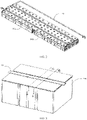
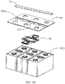
- FIG. 2 to FIG. 9 are schematic structural diagrams of fastening a fire prevention pipeline on a battery in an embodiment of this application.
- the fire prevention pipeline in the embodiments of this application is configured to accommodate a fire prevention medium, where the fire prevention medium may be fluid, and the fluid may be liquid or gas.
- the fire prevention pipeline may not accommodate any substance.
- the pressure relief mechanism is actuated, the fire prevention pipeline may accommodate the fire prevention medium.
- the fire prevention medium may be controlled to enter the fire prevention pipeline by opening and closing a valve.
- the fire prevention pipeline may always accommodate the fire prevention medium, and the fire prevention medium may alternatively be configured to regulate temperature of the battery cell. Regulating temperature means heating or cooling a plurality of battery cells.
- the fire prevention pipeline is configured to accommodate cooling fluid, to lower temperature of the plurality of battery cells.
- the fire prevention pipeline may also be referred to as a cooling part, a cooling system, or a cooling pipeline.
- the fire prevention medium accommodated by the fire prevention pipeline may also be referred to as a cooling medium or cooling fluid, and more specifically, may be referred to as a coolant or cooling gas.
- the fire prevention medium may circulate, to achieve a better temperature regulation effect.
- the fire prevention medium may be water, a mixture of water and ethylene glycol, air, or the like.
- a fastener 80 is provided on the battery cell 400.
- the fastener 80 is connected to the electrode terminal 5 of the battery cell 400.
- a fire prevention pipeline 70 is fastened to the fastener 80, so as to fasten the fire prevention pipeline 70 to the battery cell 400, where the fire prevention pipeline 80 is configured to accommodate a fire prevention medium.
- the fire prevention pipeline 70 is fastened to the electrode terminal 5.
- the fastening method of the fire prevention pipeline 70 is simplified, and fastening the fire prevention pipeline 70 becomes easier; on the other hand, the fire prevention pipeline can be fastened properly, to avoid displacement of the fire prevention pipeline in the process of thermal runaway of the battery to cause untimely fire prevention.
- FIG. 6 is a schematic diagram of connection between the fastener 80 and the battery cell 400 in this embodiment.
- the fastener 80 is provided with an accommodating portion, configured to accommodate the electrode terminal 5 of the battery cell 400.
- the accommodating portion abuts against the electrode terminal 5 to limit displacement of the fastener 80.
- the accommodating portion may alternatively be constructed to have an opening through which at least part of the electrode terminal 5 is exposed.
- a busbar 91 is configured to electrically connect to the battery cell 400, and the busbar 91 is connected to the electrode terminal 5 through the opening of the accommodating portion to limit the movement of the fastener 80 in the direction z.
- the busbar 91 may be fastened to the electrode terminal 5 by welding.
- the fastener 80 cooperates with the electrode terminal 5 by using the accommodating portion. Therefore, the fastener 80 is unable to move in the direction x and the direction y.
- the busbar 91 is provided above the fastener 80, so that the fastener 80 cannot move in the direction z.
- the electrode terminal 5 and the busbar 91 work together, so that the fastener 80 is always fastened above the pressure relief mechanism 6 of the battery cell 400, to completely restrict the position of the fire prevention pipeline and realize the fixation of the relative position of the fire prevention pipeline to the pressure relief mechanism 6.
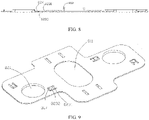
- FIG. 7 to FIG. 9 are schematic structural diagrams of a fastener 80 in some embodiments.
- the fastener 80 includes a main body 81 and a connecting portion 82 that is arranged on two sides of the main body 81.
- two connecting portions 82 are respectively located on opposite sides of the main body 81 in the direction x.
- the accommodating portion of the fastener 80 is a through hole 821 that runs through the connecting portion 82, and the through hole 821 is disposed on the electrode terminal 5.
- an accommodating portion of the fastener 80 does not run through the connecting portion 82, but runs through a recessed cavity that has an opening in the connecting portion 82.
- the recessed cavity is disposed on the electrode terminal 5, meaning that part of the electrode terminal 5 is accommodated in the recessed cavity.
- the subsequent embodiments are described by using an example in which the accommodating portion of the fastener 80 is a through hole 821 that runs through the connecting portion 82.
- the upper surface of the fastener 80 is provided with a first convex portion 822.
- the upper surface of the fastener 80 is a surface of the fastener 80 farther away from the battery cell 400, and the first convex portion 822 is arranged around the outside of the through hole 821.
- the first convex portion 822 protrudes from the electrode terminal 5 in a direction leaving the battery cell 400.
- the first convex portion 822 is provided, so that other structural components installed on the upper part of the electrode terminal 5 can directly act on the first convex portion, thereby reducing forces acting on the electrode terminal 5 and preventing the electrode terminal 5 from deforming. This further ensures that the fastener installed on the electrode terminal 5 and the fire prevention pipeline 70 installed to the fastener 80 are installed stably, improving the safety performance of the battery.
- the connecting portion 82 is also provided with a second convex portion 823.
- the second convex portion 823 protrudes from the fastener 80.
- the second convex portion 823 is close to the surface of the battery cell 400 and elastically abuts against the battery cell 400, to allow an assembly error between the fastener 80 and the battery cell 400.
- the second convex portion 823 elastically abuts against the battery cell 400, so that the upper surfaces of the plurality of fasteners 80 can be in the same horizontal plane as far as possible, helping fasten the fire prevention pipeline 70 to the plurality of fasteners 80 at the same time.
- the connecting portion 82 is provided with a run-through accommodating hole 824 and a second convex portion 823.
- the second convex portion 823 includes a fixed portion 8231 and a protruding portion 8232.
- One end of the fixed portion 8231 is configured to connect to the protruding portion 8232, and the other end of the fixed portion 8231 is configured to connect to part of hole walls of the accommodating hole 824.
- a gap is present between the protruding portion 8232 and other hole walls of the accommodating hole 824.
- the protruding portion 8232 protrudes from the fastener 80 in a direction leaving the fire prevention pipeline 70, that is, the protruding portion 8232 protrudes from the fastener 80 and approaches a surface of the battery cell 400.
- the protruding portion 8232 is elastic, and is able to bend based on the connecting portion in a direction leaving the battery cell 400 when being subject to a force in the direction leaving the battery cell 400.
- the second convex portion 823 is elastic, so that the fastener 80 and the battery cell 400 are subject to balanced forces when the fastener 80 abuts against the battery cell 400, and assembly errors are allowed between the fastener 80, the battery cell 400 and the fire prevention pipeline 70. This reduces the installation difficulty between the fastener 80, the battery cell 400 and the fire prevention pipeline 70.
- the quantity and position of the second convex portion 823 may be set according to the actual situation.
- the second convex portion 823 is provided on the fastener 80 and placed between the fastener 80 and the battery cell 400.
- the plurality of second convex portions 823 are arranged in such positions that the fastener 80 and the battery cell 400 are subject to balanced forces when the fastener 80 abuts against the battery cell 400.
- the plurality of second convex portions 823 may be symmetrically distributed around the through hole 821 or the plurality of second convex portions 823 are symmetrically distributed based on the main body 81, so that the fastener 80 and the battery cell 400 are subject to balanced forces when the fastener 80 abuts against the battery cell 400.
- the second convex portion 823 may alternatively be a spring piece or other structures, as long as it is elastic and elastically abuts against the battery cell 400 and the fastener 80 to allow an assembly error between the fastener 80 and the battery cell 400.
- the battery cell 400 is provided with a pressure relief mechanism 6.
- the pressure relief mechanism 6 is configured to be actuated when internal pressure or temperature of the battery cell 400 reaches a threshold, to release the internal pressure.
- the fire prevention pipeline 70 is configured to discharge the fire prevention medium toward the battery cell 400 when the pressure relief mechanism 6 is actuated.
- the fastener 80 is further provided with a first weak zone 811, configured to allow the emissions from the battery cell 400 to pass through the first weak zone 811 and destroy the fire prevention pipeline 70 when the pressure relief mechanism 6 is actuated, so that the fire prevention medium in the fire prevention pipeline 70 passes through the first weak zone 811 to the battery cell 400.
- the first weak zone 811 is provided on the main body 81.
- the first weak zone 811 is located above the pressure relief mechanism 6 and below the fire prevention pipeline 70, and the first weak zone 811 is provided opposite the pressure relief mechanism 6.
- a projected area of the fire prevention pipeline 70 on the first weak zone 811 is smaller than an area of the pressure relief mechanism 6.
- the first weak zone 811 may be directly provided as a through hole, or may be provided in a way other than a through hole.
- a low-melting-point material is used on the first weak zone 811, or thickness of the first weak zone 811 is reduced, so that the first weak zone 811 has a lower strength, and is easily destroyed by the emissions to form a through hole when the pressure relief mechanism 6 is actuated.
- the first weak zone 811 may also be provided to accommodate overflowing fire prevention medium when the pressure relief structure 6 is actuated and the fire prevention medium flowing to the battery cell 400 overflows, to prevent the overflowing fire prevention medium from flowing into adjacent battery cells.
- the first weak zone 811 is provided as a through hole, or a through hole is formed when the pressure relief mechanism 6 is actuated. Due to the thickness of the fastener 80, the through hole may become a accommodating pool for accommodating the fire prevention medium.
- the main body 81 of the fastener 80 is further provided with a buckle 812, which are provided on two sides of the first weak zone 811 along a central axis of the fire prevention pipeline 70, and are configured to fasten the fire prevention pipeline 70 to the fastener 80, as shown in FIG. 4 .
- the buckles 812 are arranged and spaced apart from each other to fasten the fire prevention pipeline 70. In this way, processing technology can be simplified, and greater assembly errors are allowed, helping assembly of the fire prevention pipeline 70 to the fastener 80.
- the upper surface of the fastener 80 is provided with a stiffener structure 814.
- the main body 81 is further provided with a first depression, and the stiffener structure 814 of the main body 81 is provided on the outside of the first depression.
- the first weak zone 811 and the buckle 812 are both located in the first depression.
- the first depression can accommodate at least part of the fire prevention pipeline 70, for example, at least part of the bottom of the fire prevention pipeline 70.
- the buckle 812 and the first depression may form an accommodating pool for accommodating liquid.
- the first depression can be configured to block the emissions and fire prevention medium from flowing in the direction toward the electrode terminals 5 on two sides of the main body 81, and the buckle 812 can block the emissions and fire prevention medium from flowing along an axial direction of the fire prevention pipeline 70, to effectively prevent the emissions and fire prevention medium from entering adjacent battery cells.
- the fastener 80 may be a plastic part.
- the plastic part may be produced by integral injection molding at a high efficiency.
- the fastener 80 in this embodiment not only fastens the fire prevention pipeline 70 to the battery cell, to control the battery cell 400 in thermal runaway in a timely manner and ensure the safe use of the battery, but also simplifies the installation of the fire prevention pipeline 70.
- the buckle 812, the first depression and the first weak zone 811 on the fastener 80 can form an accommodating pool to accommodate fluid, to prevent the emissions and fire prevention medium from flowing into the electrode terminal 5 and adjacent battery cells.
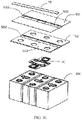
- FIG. 10 is a schematic structural diagram of a fire prevention pipeline provided on a battery according to another embodiment of this application.
- the main difference between this embodiment and the foregoing embodiment is that the battery is further provided with a separation part 92.
- the separation part 92 is made of insulation materials with an effect of insulation.
- the fastener 80 is provided between the separation part 92 and the battery cell 400, and part of the separation part 92 is located between the fastener 80 and the fire prevention pipeline 70.
- the separation part 92 is also configured for installing a busbar 91.
- the busbar 91 is connected to the electrode terminal 5, and the fastener 80 is located between the separation part 92 and the battery cell 400, to limit displacement of the fastener 80, or restrict the fastener 80 from moving in a direction leaving the battery cell 400.
- the separation part 92 is also provided with a second weak zone 921, configured to allow the emissions from the battery cells to pass through when the pressure relief mechanism 6 is actuated, so that the fire prevention medium passes through the second weak zone 921 to destroy the fire prevention pipeline 70, and the fire prevention medium in the fire prevention pipeline 70 flows to the battery cell 400.
- the second weak zone 921 may be directly provided as a through hole, or may be provided in a way other than a through hole.
- a low-melting-point material is used on the second weak zone 921, or thickness of the second weak zone 921 is reduced, so that the second weak zone 921 is destroyed by the emissions to form a through hole when the pressure relief mechanism 6 is actuated.
- the separation part 92 is provided with a second depression 922.
- the second depression 922 is provided corresponding to the first depression, and the second weak zone 921 is provided in the second depression 922.
- a plurality of through holes are provided in the second depression 922.
- the through holes are provided on two sides of the second weak zone 921 along a central axis of the fire prevention pipeline 70.
- the buckle 812 of the fastener 80 passes through the through holes to fasten the fire prevention pipeline 70.
- the fire prevention pipeline 70 may be bonded to the separation part 92.
- a structural adhesive may be used for bonding.
- FIG. 11 is a schematic structural diagram of a fire prevention pipeline provided on a battery according to still another embodiment of this application.
- the main difference between this embodiment and the foregoing embodiment is that the battery is further provided with a protection part 93.
- the protection part 93 may be made of an insulation material.
- the protection part 93 may be a mica layer.
- the protection part 93 is laid on the separation part 92 and covers the electrode terminal 5 to prevent the electrode terminal 5 from being short circuited by the emissions or fire prevention medium.
- the fire prevention pipeline 5 is located on the protection part 93.
- the protection part 93 is further provided with a third weak zone 931, configured to allow the emissions from the battery cells to pass through when the pressure relief mechanism 6 is actuated, so that the fire prevention medium passes through the third weak zone 931 to destroy the fire prevention pipeline 70, and the fire prevention medium in the fire prevention pipeline 70 flows to the battery cell 400.
- the third weak zone 931 may be directly provided as a through hole, or may be provided in a way other than a through hole.
- a low-melting-point material is used on the third weak zone 931, or thickness of the third weak zone 931 is reduced, so that the third weak zone 931 is destroyed by the emissions to form a through hole when the pressure relief mechanism 6 is actuated.
- the protection part 92 is provided with a third depression 932.
- the third depression 932 is provided corresponding to the first depression, and the third weak zone 931 is provided in the third depression 932.
- a plurality of through holes are further provided in the third depression 932, and the through holes are provided on two sides of the third depression 932 along a central axis of the fire prevention pipeline 70.
- the buckle 812 of the fastener 80 runs through the through holes to fasten the fire prevention pipeline 70.
- the third depression 932 may accommodate the condensed water formed by cooling of the hot air in the box body on the fire prevention pipeline 70 and the fire prevention medium.
- the third depression 932 and the buckle 812 of the fastener 80 may form an accommodating pool above each battery cell 400, for preventing the emissions and fire prevention medium from flowing into the electrode terminal 5 and adjacent battery cells.
- the fire prevention pipeline 70 may be bonded to the protection part 93; or the protection part 93 and the separation part 92 are fastened together, and the fire prevention pipeline 70 is fastened only to the fastener 80.
- the position to which glue is applied bypasses the third weak zone 931 when the fire prevention pipeline 70 is being bonded to the protection part 93, so that the emissions is able to break through the third weak zone 931 successfully.
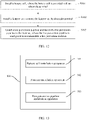
- FIG. 12 is a flowchart of a method for preparing battery according to some embodiments of this application.
- the battery is the battery according to the foregoing embodiments. This method applies to a device for preparing battery.
- the fastener is connected to the electrode terminal, to fasten the fire prevention pipeline by using the fastener.
- the fire prevention pipeline is reliably fastened, and easy to install and operate.
- FIG. 13 is a schematic composition diagram of a device for preparing battery according to some embodiments of this application.
- the battery is the battery according to the foregoing embodiments.
- the device 500 for preparing battery includes: a battery cell installation apparatus 510, a fastener installation apparatus 520, and a fire prevention pipeline installation apparatus 530.
- the battery cell installation apparatus 510 is configured to install a battery cell, where the battery cell is provided with an electrode terminal.
- the fastener installation apparatus 520 is configured to install a fastener to fasten a fire prevention pipeline, and connect the fastener to the electrode terminal.
- the fire prevention pipeline installation apparatus 530 is configured to install the fire prevention pipeline to the fastener, where the fire prevention pipeline is configured to accommodate a fire prevention medium.
- the device for preparing battery in this embodiment can connect the fastener to the electrode terminal and fasten the fire prevention pipeline by using the fastener. Compared with the conventional technology, the fire prevention pipeline is reliably fastened, and easy to install and operate.
Landscapes
- Chemical & Material Sciences (AREA)
- Chemical Kinetics & Catalysis (AREA)
- Electrochemistry (AREA)
- General Chemical & Material Sciences (AREA)
- Engineering & Computer Science (AREA)
- Manufacturing & Machinery (AREA)
- Health & Medical Sciences (AREA)
- Public Health (AREA)
- Business, Economics & Management (AREA)
- Emergency Management (AREA)
- Battery Mounting, Suspending (AREA)
- Gas Exhaust Devices For Batteries (AREA)
Abstract
Description
- This application relates to the field of battery technologies, and in particular, to a battery, an electric apparatus, and a method and a device for preparing battery.
- Due to the advantages of high energy density, high power density, a large number of charge and discharge cycles, and long storage time, lithium-ion batteries and the like have been widely used in electric vehicles.
- However, spontaneous combustion of the battery is the main factor that causes safety accidents of the electric vehicles. In order to prevent spontaneous combustion of the battery, the conventional technology typically uses a fire prevention pipeline. However, how to install the fire prevention pipeline has always been a difficult problem in the industry.
- This application provides a battery, an electric apparatus, and a method and a device for preparing battery, to fasten a fire prevention pipeline to the battery and implement timely fire prevention on a battery cell in thermal runaway to ensure the safe use of the battery.
- A first aspect of this application provides a battery, including:
- a battery cell provided with an electrode terminal;
- a fire prevention pipeline configured to accommodate a fire prevention medium; and
- a fastener configured to fasten the fire prevention pipeline, where the fastener is connected to the electrode terminal.
- In some embodiments, the fastener includes an accommodating portion, the accommodating portion is configured to accommodate the electrode terminal, and the accommodating portion abuts against the electrode terminal, to limit displacement of the fastener.
- In some embodiments, the accommodating portion is constructed to have an opening, so that at least part of the electrode terminal is exposed through the opening.
- In some embodiments, the accommodating portion is a through hole that runs through the fastener.
- In some embodiments, the fastener further includes a first convex portion, the first convex portion is provided around the periphery of the accommodating portion, and the first convex portion protrudes from the electrode terminal in a direction leaving the battery cell.
- In some embodiments, the battery further includes a second convex portion that is provided between the fastener and the battery cell, and elastically abuts against the battery cell, to allow an assembly error between the fastener and the battery cell.
- In some embodiments, the second convex portion is provided on the fastener and protrudes from a surface of the fastener closer to the battery cell.
- In some embodiments, the second convex portion is elastic.
- In some embodiments, the fastener further includes an accommodating hole that runs through the fastener. The second convex portion includes a fixed portion and a protruding portion that are connected, where one end of the fixed portion is configured to connect to the protruding portion, and the other end of the fixed portion is configured to connect to part of hole walls of the accommodating hole. A gap is present between the protruding portion and other hole walls of the accommodating hole, and the protruding portion protrudes from the surface of the fastener closer to the battery cell. When subject to a force in a direction leaving the battery cell, the protruding portion is able to bend based on a connecting portion in the direction leaving the battery cell.
- In some embodiments, a plurality of second convex portions are provided, and the plurality of second convex portions are arranged in such positions that the fastener and the battery cell are subject to balanced forces when the fastener abuts against the battery cell.
- In some embodiments, the battery cell further includes a pressure relief mechanism, and the pressure relief mechanism is configured to be actuated when internal pressure or temperature of the battery cell reaches a threshold, to release the internal pressure;
- the fire prevention pipeline is configured to discharge the fire prevention medium toward the battery cell when the pressure relief mechanism is actuated; and
- the fastener has a first weak zone, and the first weak zone is configured to allow the fire prevention medium to flow through the first weak zone to the battery cell when the pressure relief mechanism is actuated.
- In some embodiments, the first weak zone is provided as a through hole; or the first weak zone is configured to be destroyed to form a through hole when the pressure relief mechanism is actuated.
- In some embodiments, a projected area of the fire prevention pipeline on the pressure relief mechanism is smaller than an area of the pressure relief mechanism.
- In some embodiments, the fastener further includes a buckle. The buckle is configured to fasten the fire prevention pipeline to the fastener, and the buckle is provided on two sides of the first weak zone along a central axis of the fire prevention pipeline.
- In some embodiments, the fastener further includes a first depression, configured to accommodate at least part of the fire prevention pipeline, and the first weak zone and the buckle are both provided in the first depression.
- In some embodiments, the battery further includes a separation part, configured for installing a busbar. The busbar is connected to the electrode terminal, and the fastener is located between the separation part and the battery cell, to limit displacement of the fastener.
- In some embodiments, the separation part includes a second weak zone, configured to allow emissions from the battery cell to pass through the second weak zone and destroy the fire prevention pipeline when the pressure relief mechanism is actuated.
- In some embodiments, the fire prevention pipeline is bonded to the separation part.
- In some embodiments, a protection part is further included, configured to connect to the separation part;
the protection part includes a third weak zone, and the third weak zone is configured to allow the emissions from the battery cell to pass through the third weak zone and destroy the fire prevention pipeline when the pressure relief mechanism is actuated. - In some embodiments, the fire prevention pipeline is bonded to the protection part.
- In some embodiments, positions at which glue is applied bypasses the third weak zone when the fire prevention pipeline is being bonded to the protection part.
- According to another aspect of the embodiments of this application, an electric apparatus is provided, including the battery described above, where the battery is configured to supply electrical energy.
- According to another aspect of the embodiments of this application, a method for preparing battery is provided, including the following steps:
- installing a battery cell, where the battery cell is provided with an electrode terminal;
- installing a fastener and connecting the fastener to the electrode terminal; and
- installing a fire prevention pipeline and fastening the fire prevention pipeline to the fastener, where the fire prevention pipeline is configured to accommodate a fire prevention medium.
- According to another aspect of the embodiments of this application, a device for preparing battery is provided, including:
- a battery cell installation apparatus, configured to install a battery cell, where the battery cell is provided with an electrode terminal;
- a fastener installation apparatus, configured to install a fastener and connect the fastener to the electrode terminal; and
- a fire prevention pipeline installation apparatus, configured to install a fire prevention pipeline to the fastener, and the fire prevention pipeline is configured to accommodate a fire prevention medium.
- In the embodiments of this application, the fastener is provided to fasten the fire prevention pipeline to the electrode terminal reliably, so that the fire prevention pipeline can implement timely fire prevention on the battery cell, to ensure the safe use of the battery.
- To describe the technical solutions in the embodiments of this application or in the prior art more clearly, the following briefly describes the accompanying drawings for describing the embodiments or the prior art. Apparently, the accompanying drawings in the following description show some embodiments of this application, and a person of ordinary skill in the art may still derive other drawings from these accompanying drawings without creative efforts.
- The drawings described herein are intended for a further understanding of this application and constitute a part of this application. Example embodiments of this application and descriptions thereof are intended to explain this application, and do not constitute any inappropriate limitation on this application.
-
FIG. 1-A is a schematic structural diagram of an electric apparatus according to some embodiments of this application. -
FIG. 1-B is a schematic structural diagram of a battery according to some embodiments of this application. -
FIG. 1-C is a schematic structural diagram of a battery module in a battery according to some embodiments of this application. -
FIG. 1-D is a schematic structural diagram of battery cells in a battery module according to some embodiments of this application. -
FIG. 2 is a schematic structural diagram of a fire prevention pipeline provided on a battery according to an embodiment of this application. -
FIG. 3 is a partially enlarged view of a battery module in an embodiment. -
FIG. 4 is a cross-sectional view taken along the line A to A inFIG. 3 . -
FIG. 5 is a cross-sectional view taken along the line B to B inFIG. 3 . -
FIG. 6 is a schematic diagram of connection between a fastener and a battery cell in an embodiment. -
FIG. 7 is a schematic structural diagram of a fastener in an embodiment. -
FIG. 8 is a cross-sectional view taken along the line C to C inFIG. 7 . -
FIG. 9 is a bottom view ofFIG. 7 . -
FIG. 10 is a schematic structural diagram of a fire prevention pipeline provided on a battery according to another embodiment of this application. -
FIG. 11 is a schematic structural diagram of a fire prevention pipeline provided on a battery according to still another embodiment of this application. -
FIG. 12 is a flowchart of a method for preparing battery according to some embodiments of this application. -
FIG. 13 is a schematic composition diagram of a device for preparing battery according to some embodiments of this application. - Reference signs are described as follows:
- 200. battery; 210. controller; 220. motor; 201. first housing; 202. second housing;
- 300. battery module; 400. battery cell; 40. housing; 30. electrode assembly;
- 10. end cover assembly; 10'. end cover plate; 20. connecting member;
- 5. electrode terminal; 301. tab; 6. pressure relief mechanism; 2. injection member; 70. fire prevention pipeline;
- 80. fastener; 81. main body; 82. connecting portion; 821. through hole; 822. first convex portion; 823. second convex portion; 824. accommodating hole; 811. first weak zone; 812. buckle; 814. stiffener structure;
- 91. busbar;
- 92. separation part; 921. second weak zone; 922. second depression;
- 93. protection part; 931. third weak zone; 932. third depression;
- 500. device for preparing battery; 510. battery cell installation apparatus; 520. fastener installation apparatus; 530. fire prevention pipeline installation apparatus.
- To make the objectives, technical solutions, and advantages of this application more comprehensible, the following describes this application in detail with reference to embodiments and accompanying drawings. It should be understood that the specific embodiments described herein are only used to explain the application, and are preferred embodiments of this application, and are not intended to limit the scope of protection of this application. Any equivalent changes made in accordance with the structure, shape, and principle of this application shall fall within the protection scope of this application.
- Unless otherwise defined, all technical and scientific terms used herein shall have the same meanings as commonly understood by those skilled in the art to which this application belongs. The terms used in the specification of this application are merely intended to describe the specific embodiments but not intended to constitute any limitation on this application. The terms "including" and "having" and any other variations thereof in the specification, the claims and the brief description of drawings of this application are intended to cover but not exclude other content.
- The term "embodiment" described herein means that specific features, structures or characteristics in combination with descriptions of the embodiments may be incorporated in at least one embodiment of this application. The term "embodiment" in various positions in the specification does not necessarily refer to a same embodiment, or an independent or alternative embodiment that is exclusive of other embodiments. Persons skilled in the art explicitly and implicitly understand that the embodiments described herein may combine with another embodiments.
- The term "and/or" in this specification is only an associative relationship for describing associated objects, indicating that three relationships may exist. For example, A and/or B may indicate three scenarios: A alone; A and B; and B alone. In addition, a character "/" in this specification generally indicates an "or" relationship between contextually associated objects.
- In addition, the terms "first", "second" and the like in the specification and the claims or the above accompanying drawings of this application are used to distinguish between different objects but not describe a specific sequence, and can explicitly or implicitly include one or more features.
- In the descriptions of this application, unless otherwise specified, "plurality" means more than two (including two). Likewise, "a plurality of groups" means more than two groups (including two groups).
- In the descriptions of this application, it should be noted that, unless otherwise specified and defined explicitly, the terms such as "installed", "connected" and "connection" should be understood broadly. For example, "connected" or "connection" of a mechanical structure may indicate physical connection. For example, the physical connection may be fixed connection, for example, fixed connection by using a fastener such as a screw, a bolt or other fasteners; or the physical connection may be detachable connection, for example, connection by mutual clamping or clamping; or the physical connection may be an integral connection, for example, connection by welding, bonding or integral forming. "Connected" or "connection" of a circuit structure may indicate physical connection, and may also indicate electrical connection or signal connection, for example, may be direct connection, that is, the physical connection, may be indirect connection by using at least one element in between as long as circuit communication is implemented, and may also be communication between two elements; and the signal connection may be signal connection by using a circuit, and may also be signal connection by using a media medium, such as a radio wave. A person of ordinary skill in the art may understand specific meanings of the preceding terms in the embodiments of this application based on a specific situation.
- In order to clearly describe each direction in the following embodiments, some directional terms may be used. For example, the coordinate system in
FIG. 1-D defines the directions of the battery. The direction x represents a length direction of thebattery cell 400, the direction y is perpendicular to the direction x in a horizontal plane, and represents a width direction of thebattery cell 400, and the direction z is perpendicular to the direction x and the direction y, and represents a height direction of the battery. In addition, the foregoing expressions such as directions x, y and z that are used to describe indicated directions of operations and constructions of various members of the battery in the embodiments are relative rather than absolute. Although these indications are appropriate when the members of the battery are located at the positions shown in the drawings, these directions shall be interpreted differently when the positions change, to reflect the changes. - Based on the same understanding of directions, in the descriptions of this application, the directions or positional relationships indicated by the terms "center", "vertical", "transverse", "length", "width", "thickness", "upper", "lower", "front", "rear", "left", "right", "perpendicular", "horizontal", "top", "bottom", "inside", "outside", "clockwise", "counterclockwise", "axial", " radial", "circumferential", and the like are based on the directions or positional relationships shown in the accompanying drawings, are merely intended to facilitate the descriptions of this application and simplify the descriptions, are not intended to indicate or imply that the apparatuses or components mentioned in this application must have specific directions, or be constructed and operated in a specific direction, and therefore shall not be construed as a limitation to this application.
- A rechargeable battery may be referred to as a secondary battery or a traction battery. At present, the most widely used rechargeable battery is lithium battery, for example, a lithium-sulfur battery, a sodium lithium-ion battery, or a magnesium-ion battery, which is not limited. For the convenience of description, rechargeable batteries may be collectively referred to as batteries in this specification.
- Safety of a battery is an important characteristic for measuring battery performance. It is necessary to ensure the safety of the battery as much as possible when using or charging.
- The battery typically includes a plurality of battery cells that are connected. When a battery cell experiences an external short circuit, overcharge, needle puncture, plate impact, and the like, the battery cell is prone to thermal runaway. In the case of thermal runaway of the battery, emissions will be generated inside the battery cell, including but not limited to electrolyte, fragments of positive and negative electrode plates and separator because of dissolution or breaking, high-temperature and high-pressure gas and flames generated by reactions, and the like. These emissions may have thermal diffusion in the process of emission, resulting in thermal runaway of other battery cells, and even explosion and other accidents.
- Regarding thermal runaway of the battery cell, an existing effective solution is to provide a fire prevention pipeline. To be specific, when the battery cell experiences thermal runaway, a fire prevention pipeline is used to prevent or delay explosion or fire of the battery cell. The fire prevention pipeline is typically provided in the box body. When the battery cell experiences thermal runaway, the fire prevention pipeline releases a fire prevention medium to implement fire prevention. However, the inventors have found that although the fire prevention pipeline is provided, a battery using the fire prevention pipeline mentioned above still cannot implement timely fire prevention in the case of thermal runaway of the battery. In view of the foregoing problem, the inventors have tried to change the position of the fire prevention pipeline and the fire prevention manner, but none of them can solve the foregoing problem. After long term research, the inventors have further discovered that the battery provided with the fire prevention pipeline still had a safety risk because the fire prevention pipeline was displaced in the process of thermal runaway of the battery, so that the fire prevention pipeline was unable to implement timely fire prevention on the part that experiences thermal runaway. In other words, the fire prevention pipeline was not fastened reliably.
- In view of this, this application is intended to provide a battery, where an electrode terminal is connected to a fastener, to fasten the fastener to a battery cell, and a fire prevention pipeline is fastened by using the fastener. The problem of untimely fire prevention caused by displacement of the fire prevention pipeline in the process of thermal runaway of the battery in the prior art may be overcome.
- The battery in the embodiments of this application may be applied to various electric apparatuses that use electrical energy as power. The electric apparatuses herein may be, but are not limited to, electric cars, electric trains, electric bicycles, golf carts, drones, ships, and the like. In addition, the electric apparatuses may be apparatuses that use only batteries to supply power, or may be hybrid electric apparatuses. The battery supplies electrical energy to the electric apparatus, and the electric apparatus is driven by a motor.
- For example,
FIG. 1-A is a schematic structural diagram of an electric apparatus according to an embodiment of the application, where the electric apparatus may be a vehicle. The vehicle may be a fossil fuel vehicle, a natural gas vehicle, or a new energy vehicle. The new energy vehicle may be a battery electric vehicle, a hybrid electric vehicle, a range-extended vehicle, or the like. The vehicle includes abattery 200, acontroller 210, and amotor 220. Thebattery 200 is configured to supply electricity to thecontroller 210 and themotor 220 as an operating power source and a driving power source of the vehicle. For example, thebattery 200 is configured to satisfy the need for electricity during start, navigation, and operation of the vehicle. For example, thebattery 200 supplies electricity to thecontroller 210, and thecontroller 210 controls thebattery 200 to supply electricity to themotor 220. Themotor 220 receives and uses the electricity from thebattery 200 as a driving power source of the vehicle, to replace or partially replace fuel or natural gas as a driving power of the vehicle. - In order to implement a higher performance for the battery to meet usage needs, the
battery 200 may include a plurality of battery modules that are connected to each other. As shown inFIG. 1-B , thebattery 200 includes afirst housing 201, asecond housing 202, and a plurality ofbattery modules 300, where thefirst housing 201 and thesecond housing 202 are buckled to each other, and a plurality ofbattery modules 300 are arranged in a space enclosed by thefirst housing 201 and thesecond housing 202. - As shown in
FIG. 1-C , abattery module 300 includes a plurality ofbattery cells 400, and the plurality ofbattery cells 400 may be connected in series, in parallel, or in hybrid connection mode to achieve a larger current or voltage. The hybrid connection means a combination of series connection and parallel connection. For example, as shown inFIG. 1-C , thebattery cell 400 may be placed upright, a height direction of thebattery cell 400 is consistent with the vertical direction, and a plurality ofbattery cells 400 are arranged side by side in a width direction; or thebattery cell 400 may be placed flat, the width direction of thebattery cell 400 is consistent with the vertical direction, a plurality ofbattery cells 400 may be stacked in at least one layer in the width direction, and each layer includes a plurality ofbattery cells 400 that are arranged and spaced apart in a length direction. - To enable a person skilled in the art to clearly understand the improvements in this application, the overall structure of the
battery cell 400 is first described. - As shown in
FIG. 1-D , thebattery cell 400 includes ahousing 40, anelectrode assembly 30, and anend cover assembly 10. Theend cover assembly 10 includes an end cover plate 10', and the end cover plate 10' is connected to the housing 40 (for example, by welding), to form an enclosure of thebattery cell 400. Theelectrode assembly 30 is provided in thehousing 40, and thehousing 40 is filled with electrolyte. Thebattery cell 400 may be cube-shaped, cuboid-shaped or cylinder-shaped. - According to actual usage needs, one or
more electrode assemblies 30 may be configured. As shown inFIG. 1-D , at least two separatewound electrode assemblies 30 may alternatively be provided in the battery. A main body portion of theelectrode assembly 30 may be formed by stacking or winding a first electrode plate, a second electrode plate, and a separator located between the first electrode plate and the second electrode plate that are arranged adjacently, where the separator is an insulator sandwiched between the first electrode plate and the second electrode plate. The main body portion has two opposite end surfaces. In this embodiment, for example, the first electrode plate is a positive electrode plate and the second electrode plate is a negative electrode plate. A positive electrode active substance is coated on a coating zone of the positive electrode plate, and the negative electrode active substance is coated on the coating zone of the negative electrode plate. A plurality of uncoated zones extending from a coating zone of the main body portion are stacked as tabs. The electrode assembly includes two tabs 301: a positive tab and a negative tab. The positive tab extends from a coating zone of the positive electrode plate, and the negative tab extends from a coating zone of the negative electrode plate. - The
end cover assembly 10 is provided on the top of theelectrode assembly 30. As shown inFIG 1-D , theend cover assembly 10 includes an end cover plate 10' and twoelectrode terminals 5, where twoelectrode terminals 5 are a positive electrode terminal and a negative electrode terminal. Eachelectrode terminal 5 is provided with a connectingmember 20 correspondingly, and the connectingmember 20 is located between the end cover plate 10' and theelectrode assembly 30. - For example, in
FIG. 1-D , thetabs 301 of theelectrode assembly 30 are located at the top, the positive tab is connected to the positive electrode terminal by using a connectingmember 20, and the negative tab is connected to the negative electrode terminal by using another connectingmember 20. For example, thebattery cell 400 may include twoend cover assemblies 10 that are provided at two ends of thehousing 40 respectively, and eachend cover assembly 10 is provided with oneterminal 5. - The end cover plate 10' may further be provided with an explosion-proof member, to release gas in the
battery cell 400 in a timely manner when there is too much gas in thebattery cell 400, to avoid explosion. - The end cover plate 10' is provided with an exhaust hole, and the exhaust hole may be provided in a middle position of the end cover plate 10' in the length direction. The explosion-proof member includes a
pressure relief mechanism 6, and thepressure relief mechanism 6 is provided on the exhaust hole. In a normal state, thepressure relief mechanism 6 is sealed and installed on the exhaust hole. When the battery swells, and the air pressure in the enclosure rises beyond a preset value, thepressure relief mechanism 6 is actuated to open, and the gas is released outward through thepressure relief mechanism 6. - The
pressure relief mechanism 6 is a component or a part that can be actuated when internal pressure or internal temperature of thebattery cell 400 reaches a preset threshold, to release the internal pressure and/or internal substances. Thepressure relief mechanism 6 may be specifically in a form of an explosion-proof valve, a gas valve, a relief valve, a safety valve, or the like, and may specifically use a pressure-sensitive or temperature-sensitive component or structure. To be specific, when internal pressure or temperature of thebattery cell 400 reaches a preset threshold, thepressure relief mechanism 6 performs an action or a weak structure provided in thepressure relief mechanism 6 is destroyed, to form an opening or a channel for internal pressure relief. The threshold in this application may be a pressure threshold or a temperature threshold. The design of the threshold varies according to different design requirements. For example, the threshold may be designed or determined according to the internal pressure or internal temperature value of thebattery cell 400 that is considered to be dangerous or at risk of being out of control. In addition, the threshold may be determined by materials used in one or more of the positive electrode plate, negative electrode plate, electrolyte, and separator in thebattery cell 400. - The "actuation" mentioned in this application means that the
pressure relief mechanism 6 performs an action or is activated to be in a specific state, so that the internal pressure of thebattery cell 400 can be released. The actions performed by thepressure relief mechanism 6 may include but are not limited to: cracking, breaking, tearing, or opening at least part of thepressure relief mechanism 6. When thepressure relief mechanism 6 is actuated, high-temperature and high-pressure substances inside thebattery cell 400 are discharged from the actuated part as emissions. In this way, the pressure of thebattery cell 400 can be released under the condition that the pressure or temperature is controllable, to avoid more serious potential accidents. The emissions from thebattery cell 400 mentioned in this application include but are not limited to electrolyte, fragments of positive and negative electrode plates and separator because of dissolution or breaking, high-temperature and high-pressure gas and flames generated by reactions, and the like. The high-temperature and high-pressure emissions are discharged toward the direction in which thepressure relief mechanism 6 is provided on thebattery cell 400, and more specifically, can be discharged in the direction toward the area in which thepressure relief mechanism 6 is actuated. The force and destructive power of such emissions may be enormous, or even great enough to break through one or more structures such as a cover in that direction. - In some embodiments, as shown in
FIG. 1-D , the end cover plate 10' is provided with a through hole that is configured to inject electrolyte into thebattery cell 400. The through hole may be a circular hole, an elliptical hole, a polygonal hole, or a hole of other shapes, and may extend in a height direction of the end cover plate 10'. The end cover plate 10' is provided with an injection member 2 to close the through hole. -
FIG. 2 to FIG. 9 are schematic structural diagrams of fastening a fire prevention pipeline on a battery in an embodiment of this application. - The fire prevention pipeline in the embodiments of this application is configured to accommodate a fire prevention medium, where the fire prevention medium may be fluid, and the fluid may be liquid or gas. In a case that the pressure relief mechanism does not destroy the fire prevention pipeline, the fire prevention pipeline may not accommodate any substance. In a case that the pressure relief mechanism is actuated, the fire prevention pipeline may accommodate the fire prevention medium. For example, the fire prevention medium may be controlled to enter the fire prevention pipeline by opening and closing a valve. Alternatively, in a case that the pressure relief mechanism is not destroyed, the fire prevention pipeline may always accommodate the fire prevention medium, and the fire prevention medium may alternatively be configured to regulate temperature of the battery cell. Regulating temperature means heating or cooling a plurality of battery cells. In the case of cooling the battery cells, the fire prevention pipeline is configured to accommodate cooling fluid, to lower temperature of the plurality of battery cells. In this case, the fire prevention pipeline may also be referred to as a cooling part, a cooling system, or a cooling pipeline. The fire prevention medium accommodated by the fire prevention pipeline may also be referred to as a cooling medium or cooling fluid, and more specifically, may be referred to as a coolant or cooling gas. Optionally, the fire prevention medium may circulate, to achieve a better temperature regulation effect. Optionally, the fire prevention medium may be water, a mixture of water and ethylene glycol, air, or the like.
- Referring to
FIG. 2 to FIG. 6 , afastener 80 is provided on thebattery cell 400. Thefastener 80 is connected to theelectrode terminal 5 of thebattery cell 400. Afire prevention pipeline 70 is fastened to thefastener 80, so as to fasten thefire prevention pipeline 70 to thebattery cell 400, where thefire prevention pipeline 80 is configured to accommodate a fire prevention medium. - In this application, the
fire prevention pipeline 70 is fastened to theelectrode terminal 5. On the one hand, the fastening method of thefire prevention pipeline 70 is simplified, and fastening thefire prevention pipeline 70 becomes easier; on the other hand, the fire prevention pipeline can be fastened properly, to avoid displacement of the fire prevention pipeline in the process of thermal runaway of the battery to cause untimely fire prevention. -
FIG. 6 is a schematic diagram of connection between thefastener 80 and thebattery cell 400 in this embodiment. - The
fastener 80 is provided with an accommodating portion, configured to accommodate theelectrode terminal 5 of thebattery cell 400. The accommodating portion abuts against theelectrode terminal 5 to limit displacement of thefastener 80. - In a feasible implementation, the accommodating portion may alternatively be constructed to have an opening through which at least part of the
electrode terminal 5 is exposed. - A
busbar 91 is configured to electrically connect to thebattery cell 400, and thebusbar 91 is connected to theelectrode terminal 5 through the opening of the accommodating portion to limit the movement of thefastener 80 in the direction z. - In a feasible implementation, the
busbar 91 may be fastened to theelectrode terminal 5 by welding. - Using the above structure, the
fastener 80 cooperates with theelectrode terminal 5 by using the accommodating portion. Therefore, thefastener 80 is unable to move in the direction x and the direction y. Thebusbar 91 is provided above thefastener 80, so that thefastener 80 cannot move in the direction z. Theelectrode terminal 5 and thebusbar 91 work together, so that thefastener 80 is always fastened above thepressure relief mechanism 6 of thebattery cell 400, to completely restrict the position of the fire prevention pipeline and realize the fixation of the relative position of the fire prevention pipeline to thepressure relief mechanism 6. -
FIG. 7 to FIG. 9 are schematic structural diagrams of afastener 80 in some embodiments. - The
fastener 80 includes amain body 81 and a connectingportion 82 that is arranged on two sides of themain body 81. For example, two connectingportions 82 are respectively located on opposite sides of themain body 81 in the direction x. - The accommodating portion of the
fastener 80 is a throughhole 821 that runs through the connectingportion 82, and the throughhole 821 is disposed on theelectrode terminal 5. In another embodiment of this application, an accommodating portion of thefastener 80 does not run through the connectingportion 82, but runs through a recessed cavity that has an opening in the connectingportion 82. The recessed cavity is disposed on theelectrode terminal 5, meaning that part of theelectrode terminal 5 is accommodated in the recessed cavity. However, for the convenience of description, the subsequent embodiments are described by using an example in which the accommodating portion of thefastener 80 is a throughhole 821 that runs through the connectingportion 82. - The upper surface of the
fastener 80 is provided with a firstconvex portion 822. The upper surface of thefastener 80 is a surface of thefastener 80 farther away from thebattery cell 400, and the firstconvex portion 822 is arranged around the outside of the throughhole 821. When the throughhole 821 and theelectrode terminal 5 are disposed together, the firstconvex portion 822 protrudes from theelectrode terminal 5 in a direction leaving thebattery cell 400. The firstconvex portion 822 is provided, so that other structural components installed on the upper part of theelectrode terminal 5 can directly act on the first convex portion, thereby reducing forces acting on theelectrode terminal 5 and preventing theelectrode terminal 5 from deforming. This further ensures that the fastener installed on theelectrode terminal 5 and thefire prevention pipeline 70 installed to thefastener 80 are installed stably, improving the safety performance of the battery. - The connecting
portion 82 is also provided with a secondconvex portion 823. The secondconvex portion 823 protrudes from thefastener 80. When the throughhole 821 is disposed together with theelectrode terminal 5, the secondconvex portion 823 is close to the surface of thebattery cell 400 and elastically abuts against thebattery cell 400, to allow an assembly error between thefastener 80 and thebattery cell 400. To be specific, the secondconvex portion 823 elastically abuts against thebattery cell 400, so that the upper surfaces of the plurality offasteners 80 can be in the same horizontal plane as far as possible, helping fasten thefire prevention pipeline 70 to the plurality offasteners 80 at the same time. - As shown in
FIG. 8 and FIG. 9 , the connectingportion 82 is provided with a run-throughaccommodating hole 824 and a secondconvex portion 823. The secondconvex portion 823 includes a fixedportion 8231 and a protrudingportion 8232. One end of the fixedportion 8231 is configured to connect to the protrudingportion 8232, and the other end of the fixedportion 8231 is configured to connect to part of hole walls of theaccommodating hole 824. A gap is present between the protrudingportion 8232 and other hole walls of theaccommodating hole 824. When the fastener 84 is fastened to thebattery cell 400, the protrudingportion 8232 protrudes from thefastener 80 in a direction leaving thefire prevention pipeline 70, that is, the protrudingportion 8232 protrudes from thefastener 80 and approaches a surface of thebattery cell 400. The protrudingportion 8232 is elastic, and is able to bend based on the connecting portion in a direction leaving thebattery cell 400 when being subject to a force in the direction leaving thebattery cell 400. The secondconvex portion 823 is elastic, so that thefastener 80 and thebattery cell 400 are subject to balanced forces when thefastener 80 abuts against thebattery cell 400, and assembly errors are allowed between thefastener 80, thebattery cell 400 and thefire prevention pipeline 70. This reduces the installation difficulty between thefastener 80, thebattery cell 400 and thefire prevention pipeline 70. - In some feasible implementations, the quantity and position of the second
convex portion 823 may be set according to the actual situation. For example, the secondconvex portion 823 is provided on thefastener 80 and placed between thefastener 80 and thebattery cell 400. The plurality of secondconvex portions 823 are arranged in such positions that thefastener 80 and thebattery cell 400 are subject to balanced forces when thefastener 80 abuts against thebattery cell 400. For example, the plurality of secondconvex portions 823 may be symmetrically distributed around the throughhole 821 or the plurality of secondconvex portions 823 are symmetrically distributed based on themain body 81, so that thefastener 80 and thebattery cell 400 are subject to balanced forces when thefastener 80 abuts against thebattery cell 400. Similarly, the secondconvex portion 823 may alternatively be a spring piece or other structures, as long as it is elastic and elastically abuts against thebattery cell 400 and thefastener 80 to allow an assembly error between thefastener 80 and thebattery cell 400. - The
battery cell 400 is provided with apressure relief mechanism 6. Thepressure relief mechanism 6 is configured to be actuated when internal pressure or temperature of thebattery cell 400 reaches a threshold, to release the internal pressure. Thefire prevention pipeline 70 is configured to discharge the fire prevention medium toward thebattery cell 400 when thepressure relief mechanism 6 is actuated. To avoid that thepressure relief mechanism 6 is blocked and thepressure relief mechanism 6 is unable to be spouted open, and also to allow the fire prevention medium discharged from thefire prevention pipeline 70 to enter thebattery cell 400 through thepressure relief mechanism 6, thefastener 80 is further provided with a firstweak zone 811, configured to allow the emissions from thebattery cell 400 to pass through the firstweak zone 811 and destroy thefire prevention pipeline 70 when thepressure relief mechanism 6 is actuated, so that the fire prevention medium in thefire prevention pipeline 70 passes through the firstweak zone 811 to thebattery cell 400. - The first
weak zone 811 is provided on themain body 81. The firstweak zone 811 is located above thepressure relief mechanism 6 and below thefire prevention pipeline 70, and the firstweak zone 811 is provided opposite thepressure relief mechanism 6. To allow the fire prevention medium of thefire prevention pipeline 70 to pass through thepressure relief mechanism 6 and enter thebattery cell 400 as much as possible to implement a good fire prevention on thebattery cell 400 that experiences thermal runaway, a projected area of thefire prevention pipeline 70 on the firstweak zone 811 is smaller than an area of thepressure relief mechanism 6. - In some feasible implementations, the first
weak zone 811 may be directly provided as a through hole, or may be provided in a way other than a through hole. For example, a low-melting-point material is used on the firstweak zone 811, or thickness of the firstweak zone 811 is reduced, so that the firstweak zone 811 has a lower strength, and is easily destroyed by the emissions to form a through hole when thepressure relief mechanism 6 is actuated. - In some feasible implementations, the first
weak zone 811 may also be provided to accommodate overflowing fire prevention medium when thepressure relief structure 6 is actuated and the fire prevention medium flowing to thebattery cell 400 overflows, to prevent the overflowing fire prevention medium from flowing into adjacent battery cells. As shown inFIG. 5 , the firstweak zone 811 is provided as a through hole, or a through hole is formed when thepressure relief mechanism 6 is actuated. Due to the thickness of thefastener 80, the through hole may become a accommodating pool for accommodating the fire prevention medium. - The
main body 81 of thefastener 80 is further provided with abuckle 812, which are provided on two sides of the firstweak zone 811 along a central axis of thefire prevention pipeline 70, and are configured to fasten thefire prevention pipeline 70 to thefastener 80, as shown inFIG. 4 . Thebuckles 812 are arranged and spaced apart from each other to fasten thefire prevention pipeline 70. In this way, processing technology can be simplified, and greater assembly errors are allowed, helping assembly of thefire prevention pipeline 70 to thefastener 80. - The upper surface of the
fastener 80, that is, a surface farther away from thebattery cell 400, is provided with astiffener structure 814. Themain body 81 is further provided with a first depression, and thestiffener structure 814 of themain body 81 is provided on the outside of the first depression. The firstweak zone 811 and thebuckle 812 are both located in the first depression. The first depression can accommodate at least part of thefire prevention pipeline 70, for example, at least part of the bottom of thefire prevention pipeline 70. - In some feasible implementations, when the
buckle 812 is located in the first depression, thebuckle 812 and the first depression may form an accommodating pool for accommodating liquid. For example, when thepressure relief structure 6 is actuated, the first depression can be configured to block the emissions and fire prevention medium from flowing in the direction toward theelectrode terminals 5 on two sides of themain body 81, and thebuckle 812 can block the emissions and fire prevention medium from flowing along an axial direction of thefire prevention pipeline 70, to effectively prevent the emissions and fire prevention medium from entering adjacent battery cells. - In some embodiments, the
fastener 80 may be a plastic part. The plastic part may be produced by integral injection molding at a high efficiency. - Through connection to the
electrode terminal 5 of thebattery cell 400, thefastener 80 in this embodiment not only fastens thefire prevention pipeline 70 to the battery cell, to control thebattery cell 400 in thermal runaway in a timely manner and ensure the safe use of the battery, but also simplifies the installation of thefire prevention pipeline 70. In addition, thebuckle 812, the first depression and the firstweak zone 811 on thefastener 80 can form an accommodating pool to accommodate fluid, to prevent the emissions and fire prevention medium from flowing into theelectrode terminal 5 and adjacent battery cells. -
FIG. 10 is a schematic structural diagram of a fire prevention pipeline provided on a battery according to another embodiment of this application. The main difference between this embodiment and the foregoing embodiment is that the battery is further provided with aseparation part 92. - In some feasible implementations, the
separation part 92 is made of insulation materials with an effect of insulation. - The
fastener 80 is provided between theseparation part 92 and thebattery cell 400, and part of theseparation part 92 is located between thefastener 80 and thefire prevention pipeline 70. - In some feasible implementations, the
separation part 92 is also configured for installing abusbar 91. Thebusbar 91 is connected to theelectrode terminal 5, and thefastener 80 is located between theseparation part 92 and thebattery cell 400, to limit displacement of thefastener 80, or restrict thefastener 80 from moving in a direction leaving thebattery cell 400. - To avoid that the position of the
pressure relief mechanism 6 is blocked and thepressure relief mechanism 6 is unable to be spouted open, and also to allow the fire prevention medium discharged from thefire prevention pipeline 70 to enter thebattery cell 400, theseparation part 92 is also provided with a secondweak zone 921, configured to allow the emissions from the battery cells to pass through when thepressure relief mechanism 6 is actuated, so that the fire prevention medium passes through the secondweak zone 921 to destroy thefire prevention pipeline 70, and the fire prevention medium in thefire prevention pipeline 70 flows to thebattery cell 400. - In some feasible implementations, the second
weak zone 921 may be directly provided as a through hole, or may be provided in a way other than a through hole. For example, a low-melting-point material is used on the secondweak zone 921, or thickness of the secondweak zone 921 is reduced, so that the secondweak zone 921 is destroyed by the emissions to form a through hole when thepressure relief mechanism 6 is actuated. - The
separation part 92 is provided with asecond depression 922. Thesecond depression 922 is provided corresponding to the first depression, and the secondweak zone 921 is provided in thesecond depression 922. A plurality of through holes are provided in thesecond depression 922. The through holes are provided on two sides of the secondweak zone 921 along a central axis of thefire prevention pipeline 70. Thebuckle 812 of thefastener 80 passes through the through holes to fasten thefire prevention pipeline 70. - In some feasible implementations, the
fire prevention pipeline 70 may be bonded to theseparation part 92. For example, a structural adhesive may be used for bonding. -
FIG. 11 is a schematic structural diagram of a fire prevention pipeline provided on a battery according to still another embodiment of this application. The main difference between this embodiment and the foregoing embodiment is that the battery is further provided with aprotection part 93. - In some feasible implementations, the
protection part 93 may be made of an insulation material. For example, theprotection part 93 may be a mica layer. - The
protection part 93 is laid on theseparation part 92 and covers theelectrode terminal 5 to prevent theelectrode terminal 5 from being short circuited by the emissions or fire prevention medium. Thefire prevention pipeline 5 is located on theprotection part 93. - To avoid that the position of the
pressure relief mechanism 6 is blocked and thepressure relief mechanism 6 is unable to be spouted open, and also to allow the fire prevention medium discharged from thefire prevention pipeline 70 to enter thebattery cell 400 to implement a good fire prevention, theprotection part 93 is further provided with a thirdweak zone 931, configured to allow the emissions from the battery cells to pass through when thepressure relief mechanism 6 is actuated, so that the fire prevention medium passes through the thirdweak zone 931 to destroy thefire prevention pipeline 70, and the fire prevention medium in thefire prevention pipeline 70 flows to thebattery cell 400. - In some feasible implementations, the third
weak zone 931 may be directly provided as a through hole, or may be provided in a way other than a through hole. For example, a low-melting-point material is used on the thirdweak zone 931, or thickness of the thirdweak zone 931 is reduced, so that the thirdweak zone 931 is destroyed by the emissions to form a through hole when thepressure relief mechanism 6 is actuated. - The
protection part 92 is provided with athird depression 932. Thethird depression 932 is provided corresponding to the first depression, and the thirdweak zone 931 is provided in thethird depression 932. A plurality of through holes are further provided in thethird depression 932, and the through holes are provided on two sides of thethird depression 932 along a central axis of thefire prevention pipeline 70. Thebuckle 812 of thefastener 80 runs through the through holes to fasten thefire prevention pipeline 70. At the same time, thethird depression 932 may accommodate the condensed water formed by cooling of the hot air in the box body on thefire prevention pipeline 70 and the fire prevention medium. Thethird depression 932 and thebuckle 812 of thefastener 80 may form an accommodating pool above eachbattery cell 400, for preventing the emissions and fire prevention medium from flowing into theelectrode terminal 5 and adjacent battery cells. - In some feasible implementations, the
fire prevention pipeline 70 may be bonded to theprotection part 93; or theprotection part 93 and theseparation part 92 are fastened together, and thefire prevention pipeline 70 is fastened only to thefastener 80. - In some feasible implementations, the position to which glue is applied bypasses the third
weak zone 931 when thefire prevention pipeline 70 is being bonded to theprotection part 93, so that the emissions is able to break through the thirdweak zone 931 successfully. -
FIG. 12 is a flowchart of a method for preparing battery according to some embodiments of this application. The battery is the battery according to the foregoing embodiments. This method applies to a device for preparing battery. - S101. Install a battery cell, where the battery cell is provided with an electrode terminal.
- S102. Install a fastener and connect the fastener to the electrode terminal.
- S103. Install a fire prevention pipeline and fasten the fire prevention pipeline to the fastener, where the fire prevention pipeline is configured to accommodate a fire prevention medium.
- According to this embodiment, during the installation process, the fastener is connected to the electrode terminal, to fasten the fire prevention pipeline by using the fastener. Compared with the conventional technology, the fire prevention pipeline is reliably fastened, and easy to install and operate.
-
FIG. 13 is a schematic composition diagram of a device for preparing battery according to some embodiments of this application. The battery is the battery according to the foregoing embodiments. Thedevice 500 for preparing battery includes: a battery cell installation apparatus 510, a fastener installation apparatus 520, and a fire prevention pipeline installation apparatus 530. - The battery cell installation apparatus 510 is configured to install a battery cell, where the battery cell is provided with an electrode terminal.
- The fastener installation apparatus 520 is configured to install a fastener to fasten a fire prevention pipeline, and connect the fastener to the electrode terminal.
- The fire prevention pipeline installation apparatus 530 is configured to install the fire prevention pipeline to the fastener, where the fire prevention pipeline is configured to accommodate a fire prevention medium.
- The device for preparing battery in this embodiment can connect the fastener to the electrode terminal and fasten the fire prevention pipeline by using the fastener. Compared with the conventional technology, the fire prevention pipeline is reliably fastened, and easy to install and operate.
- Mutual reference may be made between the foregoing protection topics of this application and the features in the embodiments. If the structure allows, persons skilled in the art can also flexibly combine the technical features in the different embodiments to form more embodiments.
- The above describes in detail a battery, an electric apparatus, and a method and a device for preparing battery provided in this application. Specific embodiments are used in this specification to describe the principles and implementations of this application, and the descriptions of the above embodiments are merely used to help understand the methods and main ideas of this application. It should be noted that persons of ordinary skill in the art can make improvements and modifications to this application without departing from the principles of this application, and these improvements and modifications also fall within the protection scope of the claims of this application.
Claims (24)
- A battery, comprising:a battery cell provided with an electrode terminal;a fire prevention pipeline configured to accommodate a fire prevention medium; anda fastener configured to fasten the fire prevention pipeline, wherein the fastener is connected to the electrode terminal.
- The battery according to claim 1, wherein the fastener comprises an accommodating portion, the accommodating portion is configured to accommodate the electrode terminal, and the accommodating portion abuts against the electrode terminal to limit displacement of the fastener.
- The battery according to claim 2, wherein the accommodating portion is constructed to have an opening, so that at least part of the electrode terminal is exposed through the opening.
- The battery according to claim 2 or 3, wherein the accommodating portion is a through hole that runs through the fastener.
- The battery according to any one of claims 2 to 4, wherein the fastener further comprises a first convex portion, the first convex portion is provided around the periphery of the accommodating portion, and the first convex portion protrudes from the electrode terminal in a direction leaving the battery cell.
- The battery according to any one of claims 1 to 5, wherein the fastener of the battery further comprises a second convex portion that is provided between the fastener and the battery cell, and elastically abuts against the battery cell, to allow an assembly error between the fastener and the battery cell.
- The battery according to claim 6, wherein the second convex portion is provided on the fastener and protrudes from a surface of the fastener closer to the battery cell.
- The battery according to claim 6 or 7, wherein the second convex portion is elastic.
- The battery according to any one of claims 6 to 8, wherein the fastener further comprises an accommodating hole that runs through the fastener, the second convex portion comprises a fixed portion and a protruding portion that are connected, one end of the fixed portion is configured to connect to the protruding portion, the other end of the fixed portion is configured to connect to part of hole walls of the accommodating hole, a gap is present between the protruding portion and other hole walls of the accommodating hole, the protruding portion protrudes from the surface of the fastener closer to the battery cell, and the protruding portion is able to bend based on the fixed portion in a direction leaving the battery cell when the protruding portion is subject to a force in the direction leaving the battery cell.
- The battery according to any one of claims 6 to 9, wherein a plurality of second convex portions are provided, and the plurality of second convex portions are arranged in such positions that the fastener and the battery cell are subject to balanced forces when the fastener abuts against the battery cell.
- The battery according to any one of claims 1 to 10, wherein the battery cell further comprises a pressure relief mechanism, and the pressure relief mechanism is configured to be actuated when internal pressure or temperature of the battery cell reaches a threshold, to release the internal pressure;the fire prevention pipeline is configured to discharge the fire prevention medium toward the battery cell when the pressure relief mechanism is actuated; andthe fastener is provided with a first weak zone, and the first weak zone is configured to allow the fire prevention medium to flow through the first weak zone to the battery cell when the pressure relief mechanism is actuated.
- The battery according to claim 11, wherein the first weak zone is provided as a through hole; or
the first weak zone is configured to be destroyed to form a through hole when the pressure relief mechanism is actuated. - The battery according to claim 11 or 12, wherein a projected area of the fire prevention pipeline on the pressure relief mechanism is smaller than an area of the pressure relief mechanism.
- The battery according to any one of claims 11 to 13, wherein the fastener further comprises a buckle, the buckle is configured to fasten the fire prevention pipeline to the fastener, and the buckle is provided on two sides of the first weak zone along a central axis of the fire prevention pipeline.
- The battery according to claim 14, wherein the fastener further comprises a first depression, configured to accommodate at least part of the fire prevention pipeline, and the first weak zone and the buckle are both provided in the first depression.
- The battery according to any one of claims 11 to 15, wherein the battery further comprises a separation part, configured for installing a busbar, the busbar is connected to the electrode terminal, and the fastener is located between the separation part and the battery cell to limit displacement of the fastener.
- The battery according to claim 16, wherein the separation part comprises a second weak zone, configured to allow emissions of the battery cell to pass through the second weak zone and destroy the fire prevention pipeline when the pressure relief mechanism is actuated.
- The battery according to claim 16 or 17, wherein the fire prevention pipeline is bonded to the separation part.
- The battery according to any one of claims 16 and 17, further comprising a protection part, configured to connect to the separation part; wherein
the protection part comprises a third weak zone, and the third weak zone is configured to allow the emissions from the battery cell to pass through the third weak zone and destroy the fire prevention pipeline when the pressure relief mechanism is actuated. - The battery according to claim 19, wherein the fire prevention pipeline is bonded to the protection part.
- The battery according to claim 20, wherein positions at which glue is applied avoid the third weak zone when the fire prevention pipeline is being bonded to the protection part.
- An electric apparatus, comprising the battery according to any one of claims 1 to 21, wherein the battery is configured to supply electrical energy.
- A method for preparing battery, comprising the following steps:installing a battery cell, wherein the battery cell is provided with an electrode terminal;installing a fastener and connecting the fastener to the electrode terminal; andinstalling a fire prevention pipeline and fastening the fire prevention pipeline to the fastener, wherein the fire prevention pipeline is configured to accommodate a fire prevention medium.
- A device for preparing battery, comprising:a battery cell installation apparatus, configured to install a battery cell, wherein the battery cell is provided with an electrode terminal;a fastener installation apparatus, configured to install a fastener and connect the fastener to the electrode terminal; anda fire prevention pipeline installation apparatus, configured to install a fire prevention pipeline to the fastener, wherein the fire prevention pipeline is configured to accommodate a fire prevention medium.
Applications Claiming Priority (1)
| Application Number | Priority Date | Filing Date | Title |
|---|---|---|---|
| PCT/CN2020/122000 WO2022082397A1 (en) | 2020-10-19 | 2020-10-19 | Battery, electric apparatus, and method and device for preparing battery |
Publications (2)
| Publication Number | Publication Date |
|---|---|
| EP4064409A1 true EP4064409A1 (en) | 2022-09-28 |
| EP4064409A4 EP4064409A4 (en) | 2024-01-10 |
Family
ID=81289528
Family Applications (1)
| Application Number | Title | Priority Date | Filing Date |
|---|---|---|---|
| EP20957980.4A Pending EP4064409A4 (en) | 2020-10-19 | 2020-10-19 | Battery, electric apparatus, and method and device for preparing battery |
Country Status (5)
| Country | Link |
|---|---|
| US (1) | US12087965B2 (en) |
| EP (1) | EP4064409A4 (en) |
| JP (1) | JP7546755B2 (en) |
| KR (1) | KR102724404B1 (en) |
| WO (1) | WO2022082397A1 (en) |
Cited By (1)
| Publication number | Priority date | Publication date | Assignee | Title |
|---|---|---|---|---|
| EP4478487A4 (en) * | 2022-09-30 | 2025-04-09 | Contemporary Amperex Technology (Hong Kong) Limited | BATTERY AND ELECTRICAL DEVICE |
Families Citing this family (3)
| Publication number | Priority date | Publication date | Assignee | Title |
|---|---|---|---|---|
| AU2022230398A1 (en) * | 2021-03-03 | 2023-08-31 | R.P. Scherer Technologies, Llc | Branched linkers for antibody-drug conjugates and methods of use thereof |
| CN117134032B (en) * | 2023-10-25 | 2024-02-20 | 宁德时代新能源科技股份有限公司 | Battery and electric equipment |
| EP4571933A1 (en) * | 2023-12-12 | 2025-06-18 | CUSTOMCELLS Holding GmbH | Battery cell system, battery cell, cooling means, and method for operating a battery cell system |
Family Cites Families (93)
| Publication number | Priority date | Publication date | Assignee | Title |
|---|---|---|---|---|
| JP2970044B2 (en) | 1991-05-27 | 1999-11-02 | 松下電器産業株式会社 | Sealed battery |
| GB2277830B (en) | 1993-05-04 | 1996-10-23 | Programme 3 Patent Holdings | High temperature storage battery |
| CN1306679A (en) | 1999-03-22 | 2001-08-01 | 格劳瑞韦恩国际集团有限公司 | battery exhaust system |
| US20030003350A1 (en) | 2001-07-02 | 2003-01-02 | C&D Charter Holdings, Inc. | Horizontal tray insert and tray assembly for motive-power applications |
| KR100560483B1 (en) * | 2004-05-04 | 2006-03-13 | 삼성에스디아이 주식회사 | Secondary battery |
| WO2005114811A2 (en) | 2004-05-17 | 2005-12-01 | Railpower Technologies Corp. | Design of a large battery pack for a hybrid locomotive |
| KR100591421B1 (en) | 2004-09-07 | 2006-06-21 | 삼성에스디아이 주식회사 | Lithium Ion Secondary Battery with Shape Memory Safety Vent |
| KR100696685B1 (en) * | 2005-05-16 | 2007-03-20 | 삼성에스디아이 주식회사 | Secondary battery module |
| JP2008251263A (en) * | 2007-03-29 | 2008-10-16 | Sanyo Electric Co Ltd | Power supply |
| JP5377955B2 (en) | 2008-12-24 | 2013-12-25 | 三洋電機株式会社 | Power supply for vehicle |
| US9093726B2 (en) | 2009-09-12 | 2015-07-28 | Tesla Motors, Inc. | Active thermal runaway mitigation system for use within a battery pack |
| JP2012018766A (en) | 2010-07-06 | 2012-01-26 | Auto Network Gijutsu Kenkyusho:Kk | Bus bar holder |
| US8748021B2 (en) * | 2010-10-19 | 2014-06-10 | Samsung Sdi Co., Ltd. | Battery module |
| JP2012094313A (en) | 2010-10-26 | 2012-05-17 | Sanyo Electric Co Ltd | Battery unit cooling structure |
| KR101191660B1 (en) * | 2010-11-08 | 2012-10-17 | 에스비리모티브 주식회사 | Battery module |
| DE102011075318A1 (en) | 2011-05-05 | 2012-11-08 | Sb Limotive Company Ltd. | Battery housing for lithium-ion cells |
| DE102011109249A1 (en) | 2011-08-02 | 2013-02-07 | Daimler Ag | High voltage battery for vehicle applications |
| KR20130061375A (en) * | 2011-12-01 | 2013-06-11 | 삼성에스디아이 주식회사 | Battery module |
| JP6087544B2 (en) | 2012-09-04 | 2017-03-01 | 株式会社東芝 | Assembled battery |
| JP5575209B2 (en) | 2012-11-21 | 2014-08-20 | 三菱重工業株式会社 | Battery module |
| JP5761164B2 (en) | 2012-11-30 | 2015-08-12 | トヨタ自動車株式会社 | Assembled battery |
| US9614209B2 (en) | 2013-02-25 | 2017-04-04 | The Boeing Company | Aircraft including mitigation system for rechargeable batteries |
| JP5931027B2 (en) | 2013-08-29 | 2016-06-08 | 古河電気工業株式会社 | Battery module cover, battery module |
| CN106785182B (en) | 2015-11-23 | 2019-06-11 | 宁德时代新能源科技股份有限公司 | battery pack |
| JP2017139099A (en) | 2016-02-02 | 2017-08-10 | 三菱自動車工業株式会社 | Battery module |
| JP2017147128A (en) | 2016-02-17 | 2017-08-24 | 三菱重工業株式会社 | Battery module and battery system |
| JP2017152213A (en) | 2016-02-24 | 2017-08-31 | 株式会社デンソー | Fuel cell system |
| CN105762428B (en) | 2016-03-03 | 2019-06-04 | 宁德时代新能源科技股份有限公司 | battery pack |
| CN205508970U (en) | 2016-03-18 | 2016-08-24 | 山东泰汽新能源工程研究院有限公司 | Novel high safety standard's lithium ion battery peridium moves fire prevention structure that disappears |
| CN205542977U (en) | 2016-04-06 | 2016-08-31 | 北京迅力世达技术有限公司 | Battery box application has heat dissipation concurrently and puts out a fire pipeline structure of function |
| CN205583008U (en) * | 2016-05-05 | 2016-09-14 | 宁德时代新能源科技股份有限公司 | Battery module and battery module thereof |
| JP6627682B2 (en) | 2016-07-29 | 2020-01-08 | 株式会社デンソー | Battery pack |
| JP6589786B2 (en) | 2016-09-15 | 2019-10-16 | トヨタ自動車株式会社 | Battery system |
| US20180138478A1 (en) | 2016-11-14 | 2018-05-17 | Anhui Xinen Technology Co., Ltd. | Alleviating explosion propagation in a battery module |
| CN106450575B (en) | 2016-11-26 | 2019-03-05 | 华中科技大学 | A thermal management system combining heat pipe cooling and thermal protection |
| CN106356579A (en) | 2016-11-30 | 2017-01-25 | 重庆小康工业集团股份有限公司 | Safety type power battery system for electric automobile |
| EP3333932B1 (en) | 2016-12-06 | 2019-02-13 | Samsung SDI Co., Ltd. | Battery system |
| JP2018116813A (en) | 2017-01-17 | 2018-07-26 | 株式会社東芝 | Battery module and battery device |
| GB201705513D0 (en) | 2017-04-05 | 2017-05-17 | Siemens Ag | Cooling system and method |
| CN106960977A (en) * | 2017-04-28 | 2017-07-18 | 捷星新能源科技(苏州)有限公司 | A kind of multi-functional dynamic lithium battery group of high security |
| KR102203246B1 (en) * | 2017-05-25 | 2021-01-13 | 주식회사 엘지화학 | Battery module with improved safety |
| CN206834290U (en) * | 2017-05-25 | 2018-01-02 | 惠州中科新能源研究院 | A kind of type square cooling battery modules |
| KR102250180B1 (en) * | 2017-06-27 | 2021-05-07 | 주식회사 엘지화학 | Battery module, battery pack including the same, and vehicle including the same |
| JP2019029245A (en) | 2017-08-01 | 2019-02-21 | 株式会社Gsユアサ | Power storage device |
| CN207886552U (en) | 2017-09-29 | 2018-09-21 | 郑州宇通客车股份有限公司 | A kind of fire extinguishing press strip and use the battery modules of the press strip, battery case, vehicle |
| CN207474524U (en) | 2017-09-29 | 2018-06-08 | 郑州宇通客车股份有限公司 | A kind of vehicle and its battery case, battery modules, fire extinguishing component, fire extinguishment container |
| CN207474504U (en) | 2017-09-29 | 2018-06-08 | 郑州宇通客车股份有限公司 | A kind of battery and battery modules, battery case and the vehicle using the battery |
| CN107910606B (en) | 2017-10-27 | 2020-06-19 | 天津市捷威动力工业有限公司 | A lithium-ion battery pack thermal runaway control device |
| CN207909930U (en) | 2017-11-06 | 2018-09-25 | 蔚来汽车有限公司 | Battery pack storage device |
| CN207967074U (en) | 2017-11-20 | 2018-10-12 | 宁德时代新能源科技股份有限公司 | Babinet |
| CN207441811U (en) | 2017-11-20 | 2018-06-01 | 宁德时代新能源科技股份有限公司 | Babinet and battery pack |
| CN107994175B (en) | 2017-12-26 | 2024-07-26 | 广州雷利诺车业有限公司 | Electric motorcycle battery box assembly |
| CN207977389U (en) | 2018-01-29 | 2018-10-16 | 浙江美都海创锂电科技有限公司 | A kind of safety anti-explosive rectangular cell module |
| JP2019149291A (en) | 2018-02-27 | 2019-09-05 | 株式会社Gsユアサ | Manufacturing method of power storage device and power storage device |
| JP7207814B2 (en) | 2018-03-30 | 2023-01-18 | 三洋電機株式会社 | Electric vehicle with power supply and power supply |
| CN108922998A (en) | 2018-06-22 | 2018-11-30 | 安徽省力霸动力锂电池科技有限公司 | A kind of explosion-proof flame-retardant structure of lithium battery |
| CN208478517U (en) | 2018-06-28 | 2019-02-05 | 浙江衡远新能源科技有限公司 | A kind of liquid cooling structure of power battery module |
| CN110875443B (en) | 2018-08-31 | 2021-06-08 | 宁德时代新能源科技股份有限公司 | Protection component, closing cap and box |
| KR102312415B1 (en) | 2018-09-13 | 2021-10-12 | 주식회사 엘지에너지솔루션 | Battery module, battery pack comprising the battery module and vehicle comprising the battery pack |
| CN109244349A (en) | 2018-10-15 | 2019-01-18 | 王玉彪 | A kind of lithium-ion-power cell and its operating method |
| CN209249563U (en) * | 2018-12-21 | 2019-08-13 | 江苏时代新能源科技有限公司 | A kind of electrode connecting piece and battery modules |
| CN209344171U (en) | 2018-12-27 | 2019-09-03 | 北京长城华冠汽车技术开发有限公司 | A kind of liquid cooling power battery box |
| CN209490404U (en) | 2018-12-28 | 2019-10-15 | 宁德时代新能源科技股份有限公司 | A fire-fighting fluid storage device for a battery pack |
| CN111106276B (en) | 2018-12-28 | 2021-02-02 | 宁德时代新能源科技股份有限公司 | Spraying system of battery pack and battery pack |
| CN209104233U (en) | 2018-12-28 | 2019-07-12 | 宁德时代新能源科技股份有限公司 | A spray pipe assembly for a battery pack and a battery pack |
| CN209071461U (en) | 2018-12-28 | 2019-07-05 | 宁德时代新能源科技股份有限公司 | Heat management device and battery pack |
| CN111097115B (en) * | 2018-12-28 | 2021-08-20 | 宁德时代新能源科技股份有限公司 | A spray system for a battery pack and a battery pack |
| CN209662489U (en) | 2018-12-28 | 2019-11-22 | 宁德时代新能源科技股份有限公司 | A kind of spray pipeline component of battery pack, battery pack |
| KR102425695B1 (en) | 2019-01-31 | 2022-07-28 | 삼성에스디아이 주식회사 | Battery Pack |
| CN209401662U (en) | 2019-03-28 | 2019-09-17 | 宁德时代新能源科技股份有限公司 | battery pack |
| SG11202110988XA (en) | 2019-04-01 | 2021-10-28 | Spear Power Systems Inc | Apparatus for mitigation of thermal event propagation for battery systems |
| CN209592146U (en) | 2019-04-19 | 2019-11-05 | 宁德时代新能源科技股份有限公司 | Battery modules |
| CN208955153U (en) | 2019-04-30 | 2019-06-07 | 中国电力科学研究院有限公司 | Energy storage battery cluster with heat dissipation and fire protection functions |
| CN110212265A (en) | 2019-06-05 | 2019-09-06 | 武汉科技大学 | A kind of direct current charge liquid cooling battery system and its thermal management algorithm |
| CN209804782U (en) | 2019-06-19 | 2019-12-17 | 珠海格力电器股份有限公司 | battery module and battery pack |
| CN110148694B (en) | 2019-06-19 | 2024-08-27 | 珠海格力电器股份有限公司 | Battery module and battery pack |
| CN210668459U (en) | 2019-08-20 | 2020-06-02 | 深圳安凯利电池有限公司 | Explosion-proof flame retardant structure of lithium cell |
| CN110459719B (en) | 2019-08-29 | 2024-11-12 | 清华大学 | Battery pack flue gas flow duct system and battery pack |
| CN210403875U (en) | 2019-08-29 | 2020-04-24 | 惠州比亚迪实业有限公司 | Battery module, power battery package and vehicle |
| US11735788B2 (en) | 2019-09-05 | 2023-08-22 | Samsung Sdi Co., Ltd. | Energy storage module including insulation spacers and an extinguisher sheet |
| CN210535738U (en) | 2019-10-31 | 2020-05-15 | 上海蔚来汽车有限公司 | Heat insulation assembly of battery module |
| CN210723159U (en) | 2019-11-13 | 2020-06-09 | 苏州宇量电池有限公司 | Fire extinguishing power battery module and battery pack |
| CN110868645A (en) | 2019-11-22 | 2020-03-06 | 安徽飞凯电子技术有限公司 | Dampproofing communication rack |
| CN211088371U (en) | 2020-01-18 | 2020-07-24 | 赵波 | Automobile battery heat dissipation device |
| CN211700415U (en) | 2020-03-25 | 2020-10-16 | 珠海冠宇动力电池有限公司 | Busbar, busbar positioning structure, battery module and busbar assembly |
| CN111584792B (en) | 2020-04-21 | 2022-11-29 | 重庆金康动力新能源有限公司 | Battery module |
| CN111509163A (en) | 2020-05-25 | 2020-08-07 | 重庆金康动力新能源有限公司 | Battery pack with fire extinguishing function |
| CN111725454B (en) | 2020-06-12 | 2022-11-22 | 上汽通用汽车有限公司 | Battery module and battery pack assembly |
| EP3940860A1 (en) | 2020-07-16 | 2022-01-19 | ABB Schweiz AG | Battery module |
| WO2022082396A1 (en) * | 2020-10-19 | 2022-04-28 | 江苏时代新能源科技有限公司 | Battery, power utilization device, and method and device for preparing battery |
| KR102646202B1 (en) * | 2020-10-19 | 2024-03-12 | 지앙수 컨템포러리 엠퍼렉스 테크놀로지 리미티드 | Batteries, electrical devices, methods and devices for manufacturing batteries |
| EP4075589B1 (en) * | 2020-10-19 | 2026-02-25 | Jiangsu Contemporary Amperex Technology Limited | Battery, electric device, and battery manufacturing method and device |
| HUE060296T2 (en) * | 2020-10-19 | 2023-02-28 | Jiangsu Contemporary Amperex Tech Ltd | Battery, electrical device, and method and device for preparing battery |
-
2020
- 2020-10-19 WO PCT/CN2020/122000 patent/WO2022082397A1/en not_active Ceased
- 2020-10-19 JP JP2023506304A patent/JP7546755B2/en active Active
- 2020-10-19 KR KR1020237002165A patent/KR102724404B1/en active Active
- 2020-10-19 EP EP20957980.4A patent/EP4064409A4/en active Pending
-
2023
- 2023-04-03 US US18/295,151 patent/US12087965B2/en active Active
Cited By (1)
| Publication number | Priority date | Publication date | Assignee | Title |
|---|---|---|---|---|
| EP4478487A4 (en) * | 2022-09-30 | 2025-04-09 | Contemporary Amperex Technology (Hong Kong) Limited | BATTERY AND ELECTRICAL DEVICE |
Also Published As
| Publication number | Publication date |
|---|---|
| US20230238646A1 (en) | 2023-07-27 |
| KR20230027220A (en) | 2023-02-27 |
| JP2023542791A (en) | 2023-10-12 |
| US12087965B2 (en) | 2024-09-10 |
| EP4064409A4 (en) | 2024-01-10 |
| KR102724404B1 (en) | 2024-10-30 |
| WO2022082397A1 (en) | 2022-04-28 |
| JP7546755B2 (en) | 2024-09-06 |
Similar Documents
| Publication | Publication Date | Title |
|---|---|---|
| EP3965216B1 (en) | Battery and related apparatus therefor, preparation method, and preparation device | |
| US12087965B2 (en) | Battery, electric apparatus, and method and device for preparing battery | |
| CN112018301B (en) | Battery, electrical device, method and device for preparing battery | |
| EP3965217B1 (en) | Battery, related apparatus therefor, preparation method therefor, and preparation device therefor | |
| CN112018462B (en) | Battery, electric device, and method and equipment for preparing battery | |
| EP4071897A1 (en) | End cap assembly, battery cell and manufacturing method therefor, battery and power device | |
| KR20230110440A (en) | Battery box body, battery, electric device, battery manufacturing method and device | |
| US12183941B2 (en) | Battery, power consumption device, and method and device for producing battery | |
| CN115398728B (en) | Battery, power utilization device, method and device for preparing battery | |
| WO2023133735A1 (en) | Battery, power consuming apparatus, and method and apparatus for preparing battery | |
| US20250062495A1 (en) | Battery cell, battery, and electric device | |
| JP7700355B2 (en) | BATTERY, ELECTRIC DEVICE, METHOD AND APPARATUS FOR MANUFACTURING BATTERY | |
| RU2805991C1 (en) | Battery and device associated with it, method for its manufacture and device for its manufacture | |
| US12567639B2 (en) | Box, battery, electrical apparatus, and method and apparatus for preparing battery | |
| US20230344017A1 (en) | Battery, electric apparatus, and method and apparatus for preparing battery | |
| US11973243B2 (en) | Battery, power consumption device, and method and device for producing battery | |
| US20250174780A1 (en) | Battery cell, battery, and electric device |
Legal Events
| Date | Code | Title | Description |
|---|---|---|---|
| STAA | Information on the status of an ep patent application or granted ep patent |
Free format text: STATUS: THE INTERNATIONAL PUBLICATION HAS BEEN MADE |
|
| PUAI | Public reference made under article 153(3) epc to a published international application that has entered the european phase |
Free format text: ORIGINAL CODE: 0009012 |
|
| STAA | Information on the status of an ep patent application or granted ep patent |
Free format text: STATUS: REQUEST FOR EXAMINATION WAS MADE |
|
| 17P | Request for examination filed |
Effective date: 20220624 |
|
| AK | Designated contracting states |
Kind code of ref document: A1 Designated state(s): AL AT BE BG CH CY CZ DE DK EE ES FI FR GB GR HR HU IE IS IT LI LT LU LV MC MK MT NL NO PL PT RO RS SE SI SK SM TR |
|
| A4 | Supplementary search report drawn up and despatched |
Effective date: 20231211 |
|
| RIC1 | Information provided on ipc code assigned before grant |
Ipc: H01M 50/543 20210101ALI20231205BHEP Ipc: H01M 50/30 20210101ALI20231205BHEP Ipc: H01M 50/342 20210101ALI20231205BHEP Ipc: H01M 10/04 20060101ALI20231205BHEP Ipc: H01M 10/42 20060101AFI20231205BHEP |
|
| DAV | Request for validation of the european patent (deleted) | ||
| DAX | Request for extension of the european patent (deleted) |