EP4064231A1 - Système, procédé et produit programme informatique pour l'ouverture automatique d'un portail d'une station de transport public - Google Patents
Système, procédé et produit programme informatique pour l'ouverture automatique d'un portail d'une station de transport public Download PDFInfo
- Publication number
- EP4064231A1 EP4064231A1 EP21164341.6A EP21164341A EP4064231A1 EP 4064231 A1 EP4064231 A1 EP 4064231A1 EP 21164341 A EP21164341 A EP 21164341A EP 4064231 A1 EP4064231 A1 EP 4064231A1
- Authority
- EP
- European Patent Office
- Prior art keywords
- gate
- user status
- identifier
- signal
- passenger
- Prior art date
- Legal status (The legal status is an assumption and is not a legal conclusion. Google has not performed a legal analysis and makes no representation as to the accuracy of the status listed.)
- Pending
Links
- 238000000034 method Methods 0.000 title claims description 39
- 238000004590 computer program Methods 0.000 title claims description 20
- 238000010200 validation analysis Methods 0.000 claims abstract description 73
- 238000007726 management method Methods 0.000 claims description 90
- 238000013500 data storage Methods 0.000 claims description 20
- 238000004891 communication Methods 0.000 description 25
- 238000005516 engineering process Methods 0.000 description 23
- 230000008569 process Effects 0.000 description 17
- 230000000694 effects Effects 0.000 description 8
- 238000004364 calculation method Methods 0.000 description 7
- 230000006870 function Effects 0.000 description 7
- 230000003287 optical effect Effects 0.000 description 7
- 238000010586 diagram Methods 0.000 description 6
- 238000012545 processing Methods 0.000 description 4
- 230000026676 system process Effects 0.000 description 4
- 238000012986 modification Methods 0.000 description 3
- 230000004048 modification Effects 0.000 description 3
- 230000006855 networking Effects 0.000 description 3
- 239000004065 semiconductor Substances 0.000 description 3
- 238000012546 transfer Methods 0.000 description 3
- 230000005540 biological transmission Effects 0.000 description 2
- 238000011960 computer-aided design Methods 0.000 description 2
- 230000006978 adaptation Effects 0.000 description 1
- 230000004888 barrier function Effects 0.000 description 1
- 230000008901 benefit Effects 0.000 description 1
- 238000010276 construction Methods 0.000 description 1
- 230000006872 improvement Effects 0.000 description 1
- 238000004519 manufacturing process Methods 0.000 description 1
- 238000005259 measurement Methods 0.000 description 1
- 230000002093 peripheral effect Effects 0.000 description 1
- 230000004044 response Effects 0.000 description 1
- 238000006467 substitution reaction Methods 0.000 description 1
- 230000007704 transition Effects 0.000 description 1
Images


Classifications
-
- G—PHYSICS
- G07—CHECKING-DEVICES
- G07B—TICKET-ISSUING APPARATUS; FARE-REGISTERING APPARATUS; FRANKING APPARATUS
- G07B15/00—Arrangements or apparatus for collecting fares, tolls or entrance fees at one or more control points
- G07B15/02—Arrangements or apparatus for collecting fares, tolls or entrance fees at one or more control points taking into account a variable factor such as distance or time, e.g. for passenger transport, parking systems or car rental systems
- G07B15/04—Arrangements or apparatus for collecting fares, tolls or entrance fees at one or more control points taking into account a variable factor such as distance or time, e.g. for passenger transport, parking systems or car rental systems comprising devices to free a barrier, turnstile, or the like
-
- G—PHYSICS
- G07—CHECKING-DEVICES
- G07C—TIME OR ATTENDANCE REGISTERS; REGISTERING OR INDICATING THE WORKING OF MACHINES; GENERATING RANDOM NUMBERS; VOTING OR LOTTERY APPARATUS; ARRANGEMENTS, SYSTEMS OR APPARATUS FOR CHECKING NOT PROVIDED FOR ELSEWHERE
- G07C9/00—Individual registration on entry or exit
- G07C9/10—Movable barriers with registering means
-
- G—PHYSICS
- G07—CHECKING-DEVICES
- G07C—TIME OR ATTENDANCE REGISTERS; REGISTERING OR INDICATING THE WORKING OF MACHINES; GENERATING RANDOM NUMBERS; VOTING OR LOTTERY APPARATUS; ARRANGEMENTS, SYSTEMS OR APPARATUS FOR CHECKING NOT PROVIDED FOR ELSEWHERE
- G07C9/00—Individual registration on entry or exit
- G07C9/20—Individual registration on entry or exit involving the use of a pass
-
- H—ELECTRICITY
- H04—ELECTRIC COMMUNICATION TECHNIQUE
- H04W—WIRELESS COMMUNICATION NETWORKS
- H04W12/00—Security arrangements; Authentication; Protecting privacy or anonymity
- H04W12/08—Access security
-
- H—ELECTRICITY
- H04—ELECTRIC COMMUNICATION TECHNIQUE
- H04W—WIRELESS COMMUNICATION NETWORKS
- H04W4/00—Services specially adapted for wireless communication networks; Facilities therefor
- H04W4/30—Services specially adapted for particular environments, situations or purposes
- H04W4/40—Services specially adapted for particular environments, situations or purposes for vehicles, e.g. vehicle-to-pedestrians [V2P]
- H04W4/42—Services specially adapted for particular environments, situations or purposes for vehicles, e.g. vehicle-to-pedestrians [V2P] for mass transport vehicles, e.g. buses, trains or aircraft
-
- G—PHYSICS
- G07—CHECKING-DEVICES
- G07C—TIME OR ATTENDANCE REGISTERS; REGISTERING OR INDICATING THE WORKING OF MACHINES; GENERATING RANDOM NUMBERS; VOTING OR LOTTERY APPARATUS; ARRANGEMENTS, SYSTEMS OR APPARATUS FOR CHECKING NOT PROVIDED FOR ELSEWHERE
- G07C9/00—Individual registration on entry or exit
- G07C9/20—Individual registration on entry or exit involving the use of a pass
- G07C9/27—Individual registration on entry or exit involving the use of a pass with central registration
-
- G—PHYSICS
- G07—CHECKING-DEVICES
- G07C—TIME OR ATTENDANCE REGISTERS; REGISTERING OR INDICATING THE WORKING OF MACHINES; GENERATING RANDOM NUMBERS; VOTING OR LOTTERY APPARATUS; ARRANGEMENTS, SYSTEMS OR APPARATUS FOR CHECKING NOT PROVIDED FOR ELSEWHERE
- G07C9/00—Individual registration on entry or exit
- G07C9/20—Individual registration on entry or exit involving the use of a pass
- G07C9/28—Individual registration on entry or exit involving the use of a pass the pass enabling tracking or indicating presence
-
- G—PHYSICS
- G07—CHECKING-DEVICES
- G07C—TIME OR ATTENDANCE REGISTERS; REGISTERING OR INDICATING THE WORKING OF MACHINES; GENERATING RANDOM NUMBERS; VOTING OR LOTTERY APPARATUS; ARRANGEMENTS, SYSTEMS OR APPARATUS FOR CHECKING NOT PROVIDED FOR ELSEWHERE
- G07C9/00—Individual registration on entry or exit
- G07C9/20—Individual registration on entry or exit involving the use of a pass
- G07C9/29—Individual registration on entry or exit involving the use of a pass the pass containing active electronic elements, e.g. smartcards
Definitions
- the present subject matter in particular relates to a system for automatically opening a gate of a public transport station for a passenger by using a mobile device.
- a corresponding method and computer program product are provided as well.
- Mobile computer based public transportation management systems are increasingly common. These systems, for example, determine when a passenger gets on and off different stations/means of transport, determine the travelling route which was taken by the passenger and some may even calculate the fare based on the passengers' location information provided by the passengers' mobile devices.
- a passenger only carry a mobile device when using such a system. In the following a passenger equipped with a mobile device is referred to as a user.
- Patent Literature 1 describes a method for determining a location history of a mobile device. Different states corresponding to different reachable road segments associated with a road network are determined based on several initial estimated locations of the mobile device, and a mobility model defining transition probabilities between the determined states is generated.
- Patent Literature 1 EP 3045931 A1
- the disclosed system for automatically opening a gate of a public transport station is part of a mobile computer based public transportation management systems as described above.
- the present disclosure addresses the technical object of improving the flow of passengers through a station without increasing the computational and measuring efforts of a present mobile computer based public transportation management system. This object is achieved by the subject matter of the appended claims.
- a gate system including a plurality of gates which can open automatically and a system for opening a gate of a public transport station automatically comprising a plurality of transmitters, at least one mobile device of a passenger and a gate system including a plurality of gates controlled by a plurality of gate control devices.
- Said system for opening a gate of a public transport station preferably includes the gate system as claimed by appended claim 1.
- a public transport station may preferably be a train station, a bus station, or the like having entrances/exits to the station, to one or more platforms of the station and/or to one or more public means of transport such as trains or busses.
- a gate of a public transport station may preferably be an automatically opening electric passenger gate comprising a turnstile, a swing door or any other movable barrier that enables a single passenger to pass through the gate in entrance or exit direction.
- the gate may be located at an entrance/exit of a public transport station and/or at an entrance/exit of a platform.
- the gate may also be located inside a public transport station and separate different platforms from one another.
- the gate may be located at an entrance/exit of a public means of transport such as a station platform screen door separating platform and rails.
- the plurality of gates which are controlled by the present system may even be located close to each other without impairing the present system's function.
- the plurality of transmitters may be implemented using any appropriate hardware and/or software configured for wireless communication with a mobile device of a passenger.
- a transmitter may act as a stand-alone device including a processor, communication module, and/or network interface component configured to communicate with a mobile device of a passenger, the plurality of gate control devices and/or a service provider server.
- a transmitter emits signals in a predefined range around the transmitter periodically and/or constantly.
- the plurality of transmitters may preferably comprise UWB (ultra-wideband) tags, active RFID (radio-frequency identification) tags, WLAN (wireless local area network) tags and/or BLE (Bluetooth low energy; Bluetooth is a registered trademark) tags ("beacons").
- the predefined transmission range of the transmitter may preferably in the range of 0.1 m to 100 m. Most preferably the predefined transmission range of the transmitter may be in the range of 0.1 m to 10 m.
- Each transmitter may be installed at one of a plurality of gates and may send a transmitter signal including a gate identifier identifying the respective gate.
- the term "installed at” shall be understood in the sense of “connected to”, “mounted on” and/or “included in”. Identifying a gate by a gate identifier shall include that each gate has an exclusive gate identifier pinpointing the respective gate.
- a mobile device of a passenger reaching the plurality of gates may receive a plurality of transmitter signals from the plurality of transmitters and may select one of the plurality of received transmitter signals based on a signal characteristic of the received transmitter signals.
- the term "reaching" may mean that a passenger is approaching the gates or that the passenger is getting closer thereto or that the passenger arrives within a certain, definable range/vicinity of the gates.
- the passenger's mobile device may select (automatically) the transmitter signal having the highest signal strength and/or the highest signal frequency as will be described below. Since the signal strength and the signal frequency correspond to the distance of a user to a transmitter, the signal received from the transmitter closest to the user may be selected.
- the passenger's mobile device may interact with the transmitters sending a transmitter signal via a radio signal or the like that can be received wirelessly by the mobile device when it is positioned within range of the transmitter signals.
- the mobile device may be a smartphone, a tablet, a laptop, a smart watch, or the like.
- the mobile device may further preferably have a graphic user interface for displaying relevant information to the user of the mobile device.
- the plurality of gate control devices may be connected to the gates to be controlled.
- each gate control device may be connected to a single gate.
- a gate control device may preferably be included in the gate or attached to the gate. It may also be possible that a gate control device is positioned remote from the gate.
- Each gate control device may be electrically connected to the gate to be controlled via a cable or wirelessly.
- each gate control device may receive the gate identifier of the connected gate from the transmitter installed at the connected gate, and/or from a data storage in which the gate identifier of the connected gate may be stored. Any other possibility for a gate control device to receive the gate identifier of the connected gate can also be used.
- Each gate control device may further be configured to communicate with a mobile device of a passenger and/or stationary server.
- the passenger's mobile device may read the gate identifier included in the selected transmitter signal and may transmit a validation signal including the gate identifier of the selected transmitter signal and a user identifier of the passenger's mobile device to the plurality of gate control devices controlling the plurality of gates.
- the user identifier may be an identifier which unambiguously defines the passenger's mobile in the context of a mobile computer based public transportation management system.
- the validation signal can be used to identify the gate selected for entering/leaving a station/platform as well as the user intending to enter or leave the station/platform through the selected gate.
- Each of the plurality of gate control devices may receive the validation signal from the passenger's mobile device and may compare the gate identifier included in the received validation signal with a gate identifier of the gate controlled by the gate control device.
- a gate control device may open the gate if the gate identifier included in the received validation signal corresponds to the gate identifier of the gate controlled by the gate control device. In other words, a comparison is made between the gate identifier included in the received validation signal and the gate identifier of the gate connected to the control device. If the gate identifier included in the validation signal matches to the gate identifier of the gate to which the gate controller is connected, the gate controller may open the gate.
- the disclosed subject matter allows for improving the flow of passengers through a station by automatically opening a gate of a public transport station for a passenger equipped with a mobile device (user) when the user arrives at the gate. It may also possible to direct a user through the nearest gate when he/she reaches a plurality of gates installed at an entrance/exit of a station/platform. This enables to optimize the users' route within the station without increasing the computational and measuring effort of a present mobile computer based public transportation management system. Instead, components of an existing system can be synergistically used to automatically and hands-free opening a gate located closest to a user.
- the signal characteristic of the received transmitter signals may be a signal strength and/or a signal frequency.
- the signal strength may preferably be represented by the RSSI value (received signal strength indication) referring to a signal power level determined in a calibration process one meter away from the transmitter.
- the RSSI value may be in a range of -120 dbm to 0 dbm. The higher the RSSI value (i.e., the closer the RSSI value to 0 dbm), the closer the user is located to a transmitter, and thus to the gate to be passed. This means that the passenger's mobile device may select the transmitter signal having the highest RSSI value.
- a predefined RSSI threshold value may be defined for the received transmitter signals, which must be exceeded by each transmitter signal before the signal with the highest RSSI value can be selected.
- the distance to a transmitter installed at a gate may be determined using a signal frequency.
- the signal frequency may be the frequency by which a passenger's mobile device receive a periodically sent transmitter signal. The higher the frequency, the closer the user is located to a transmitter, and thus to a gate to be passed. This means that the passenger's mobile device may select the transmitter signal having the highest signal frequency.
- the gate identifier of each transmitter signal received by the passenger's mobile device may preferably be stored in a gate identifier list and provided with a time stamp. Additionally, the signal strength may preferably be stored in the gate identifier list.
- the signal frequency may be determined based on the sum of the number of gate identifiers stored in the gate identifier list at a specific time or during a specific time period.
- the signal frequency may be determined by dividing the sum of the number of gate identifiers stored in the gate identifier list by a specific time period starting.
- the specific time period may be determined based on the time period from the first specific time when a gate identifier is stored in the gate identifier list to the last specific time when the gate identifier is stored in the gate identifier list.
- the gate identifier list may be cleared.
- the above-described procedure allows for automatically opening the gate closest to the user by means of its mobile device without the need for complex distance measurement equipment. Determining the signal strength and/or the signal frequency based on data already integrated in the gate identifier list also helps to reduce computational effort for analysing the received transmitter signals.
- the system may comprise a back office including a back-office data storage unit for storing user status data of a plurality of mobile devices of passengers in a user status management table.
- the back office may preferably be a stationary server or a plurality of stationary servers.
- the term "back office" shall generally describe a remotely located computer facility, such as remote computer(s), server(s), processor(s), storage device(s), and the like.
- the server(s) may further preferably be connected to a mobile device of a passenger and the plurality of gate control units via a wireless data connection such as the internet, a mobile network, or a wireless local area network.
- the back-office data storage unit may be a data storage unit, which can store information storable in a in a gate identifier table and a user status management table.
- the back-office data storage unit may preferably be an internal storage unit for storing, among others, user status data of a plurality of mobile devices of passengers in a database which is preferably structured as a table, another suitable data format or the like.
- the data storage may preferable be provided with the stationary server/the plurality of stationary servers. It may also be possible that the data storage is provided with the passenger's mobile device or another remote location.
- the data storage may also be distributed over different storage places.
- the gate identifier table may preferably be configured to store a gate identifier corresponding to a location of the gate identified by the gate identifier.
- the user status management table may preferably be configured to store a user identifier of each passenger's mobile device, a location of a user/passenger's mobile device, a time stamp indicating the time of determining the location of the user/the passenger's mobile device and a user status.
- the back office may further comprise a user status management unit which may receive a user status request including the user identifier of the passenger's mobile device from the gate control device controlling the gate to be opened.
- the user status management unit of the back office may read a previous user status from the user status management table.
- the term "user status” may be understood as the status of a passenger equipped with a mobile device (user) using a facility of public transportation such as a train station or bus station and its corresponding means of transportation such as train or bus. This may include activities such as waiting for a means of transportation at a respective station, being onboard a means transportation or entering a station, being inside/outside a station or the like.
- the user status may preferably include “inside” and “outside”, wherein “inside” indicates that the passenger equipped with his/her mobile device (user) is positioned inside a station/platform and “outside” indicates that the passenger is positioned “outside” a station/platform.
- the user status management unit may determine a current user status based on the previous user status.
- the user status management unit may identify the status data of a passenger equipped with a mobile device (user) stored in the user status management table via the received user identifier and may read out the user status of the identified user with the latest time stamp from the user status management table as previous user status.
- the user status management unit of the back office may transmit the current user status to the gate control device controlling the gate to be opened.
- the current user status may be understood as a status a user intending to pass a gate may achieve by passing the gate.
- the gate control device controlling the gate to be opened may receive the current user status and may determine an opening direction of the gate according to the received current user status so that the gate can be automatically opened for the user in the correct direction without time lag.
- the user status management unit of the back office may determine the current user status to be "inside” if no previous user status is stored in the user status management table. In this case, it is assumed that the user must be outside a station/platform, since no status information is available. In other words, it is assumed that the previous user status is "outside”. Furthermore, the user status management unit of the back office may determine the current user status to be "inside” if the previous user status stored in the user status management table is "outside". By determining the door opening direction on the basis of data tables already stored in the back-office data storage unit, the user status does not have to be calculated, so that no additional computing effort is required.
- the user status management unit of the back office may determine the current user status to be "outside” if the previous user status stored in the user status management table is "inside".
- the gate control device may control the gate to be opened to open in entrance direction if the current user status is "inside” and may control the gate to be opened in exit direction if the current user status is "outside".
- the user status management unit of the back office may determine a current location of a user based on the gate identifier included in the received status request.
- the current location of the user can be determined by determining the location of the gate that the user has just passed using the gate identifier table in which each gate identifier may be stored in connection with the location of the corresponding gate.
- the user status management unit may update the user status management table according to the determined current user status and the determined current location of the user.
- the user status management unit may write the current user status provided with a time stamp as well as the current user location in the respective columns of the status management table.
- the passenger's mobile device may include a transmitter signal receiver unit, which may receive a plurality of transmitter signals each including a gate identifier from a plurality of transmitters installed at a plurality of gates.
- the transmitter signal receiver unit may receive the transmitter signals via a wireless communication such as a wireless local area network, Bluetooth low energy (Bluetooth is a registered trademark), ultra-wideband and the like.
- the transmitter signal receiver unit may be configured to continuously update a gate identifier list every time a gate identifier included in a transmitter signal is received and store the received gate identifier together with a time stamp in the gate identifier list.
- the mobile device may include a mobile device data storage unit, which may store the above-described gate identifier list.
- the mobile device data storage unit may preferably be an internal storage unit for storing a gate identifier list in a database which is preferably structured as a table, another suitable data format or the like.
- the data storage may be provided with the user's mobile device or another remote location. The data storage may also be distributed over different storage places.
- the gate identifier list may be preferably stored in a table.
- the table may, for example, comprise a first column in which the received gate identifiers are listed, a second column in which the time stamps corresponding to the gate identifiers are listed, and a third column in which the corresponding signal strengths of the received transmitter signals are listed.
- the passenger's mobile device may include a validation signal generator unit, which may select one of the received transmitter signals stored in the gate identifier list based on a signal characteristic such as the signal strength and/or the signal frequency of the received transmitter signals.
- the validation signal generator unit may read the gate identifier of the selected signal from the gate identifier list and generate a validation signal including the gate identifier of the selected transmitter signal and a user identifier of the passenger's mobile device.
- the passenger's mobile device may include a validation signal transmitter unit configured to transmit the generated validation signal to a plurality of gate control devices.
- the gate identifier list may be cleared.
- the validation signal transmitter unit may transmit the validation signal via a wireless communication such as a wireless local area network, Bluetooth low energy (Bluetooth is a registered trademark), ultra-wideband and the like.
- a wireless communication such as a wireless local area network, Bluetooth low energy (Bluetooth is a registered trademark), ultra-wideband and the like.
- each of the plurality of gate control devices may include a signal receiver unit, which may receive a validation signal from a mobile device of a passenger and a current user status from a user status management unit of a back office.
- the signal receiver unit may receive the validation signal from the passenger's mobile device via a wireless communication such as a wireless local area network, Bluetooth low energy (Bluetooth is a registered trademark), ultra-wideband and the like, and may receive the current user status from the user status management unit of the back office via a wireless data connection such as the internet, a mobile network, a wireless local area network and the like.
- each of the plurality of gate control devices may include a signal analyser unit, which may compare a gate identifier included in the received validation signal with a gate identifier of a gate controlled by the gate control device and may determine an opening direction of the gate according to the received current user status.
- the signal analyser unit may compare a gate identifier included in the received validation signal with a gate identifier of a gate controlled by the gate control device and may determine an opening direction of the gate according to the received current user status.
- each of the plurality of gate control devices may include a gate opening control unit which may control the gate to open if the gate identifier included in the received validation signal corresponds to the gate identifier of the gate controlled by the gate control device. Further, the gate opening control unit may control the gate to open in entrance direction if the current user status is "inside", and in exit direction if the current user status is "outside”.
- a method for automatically opening a gate of a public transport station may comprise the steps: sending, by a plurality of transmitters, each transmitter being installed at one of a plurality of gates, transmitter signals each including a gate identifier identifying the respective gate; receiving, by a mobile device of a passenger reaching the plurality of gates, the plurality of transmitter signals; selecting, by the passenger's mobile device, one of the plurality of received transmitter signals based on a signal characteristic of the received transmitter signals; reading, by the passenger's mobile device, the gate identifier included in the selected transmitter signal; transmitting, by the passenger's mobile device, a validation signal including the gate identifier of the selected transmitter signal and a user identifier of the passenger's mobile device to a plurality of gate control devices controlling the plurality of gates; receiving, by each of the plurality of gate control devices, the validation signal from the passenger's mobile device; comparing, by each of the plurality of gate control devices, the gate identifier included in the
- the method may further comprise the steps: receiving, by a user status management unit of a back office, a user status request including the user identifier of the passenger's mobile device from the gate control device controlling the gate to be opened; reading, by the user status management unit, a previous user status from the user status management table based on the user identifier included in the received status request; determining, by the user status management unit, a current user status based on the previous user status; transmitting, by the user status management unit, the current user status to the gate control device controlling the gate to be opened; receiving, by the gate control device controlling the gate to be opened, the current user status; and determining, by the gate control device controlling the gate to be opened, an opening direction of the gate according to the received current user status.
- the current user status may be determined to be "inside” by the user status management unit if no previous user status is stored in the user status management table, or if the previous user status stored in the user status management table is "outside", and the current user status may be determined to be "outside” if the previous user status stored in the user status management table is "inside”.
- the gate to be opened may be controlled by the gate control device to open in entrance direction if the current user status is "inside” and to open in exit direction if the current user status is "outside".
- a current location of the user may be determined by the user status management unit based on the gate identifier included in the received status request, and the user status management table may be updated by the user status management unit according to the determined current user status and the determined current location of the passenger's mobile device.
- each configuration of the claimed system shall also be encompassed by way of a method, which may be claimed by itself and/or by way of a computer program product claim in another aspect of the present disclosure.
- the disclosed subject matter allows for improving the flow of passengers through a station by automatically opening the gate at which the user arrives when entering/leaving a station/a platform.
- This improvement can be achieved without increasing the computational and measuring effort of a present mobile computer based public transportation management system by using available technology already installed therein.
- it may be possible to optimize the route of the users within the station by opening the gate closest to the user with a short advance in order to guide him/her thereto.
- the user status does not have to be calculated, so that no additional computing effort is required.
- FIG 1 shows schematically a passenger equipped with a mobile device (user) 100 reaching two exemplary gates 1200, 1300 of a public transport station, such as a train station or a bus station, from the outside of the station/platform.
- the depicted gates 1200, 1300 each comprise a turnstile 1220, 1320, a gate control device 1210, 1310 and a transmitter 1201, 1301.
- Each transmitter 1201, 1301 may periodically or constantly send transmitter signals, such as radio signals, including a gate identifier that uniquely identifies the gate 1200, 1300 at which the transmitter 1201, 1301 is installed.
- the depicted user 100 carries a mobile device 1100 that may receive the transmitter signals including the gate identifiers (illustrated as arrows with dotted lines) from the two transmitters 1201, 1301 installed at the gates 1200, 1300. After receiving the transmitter signals, the passenger's mobile device 1100 may store the gate identifiers included in the two transmitter signals in a gate identifier list and select the gate identifier included in the signal having the highest signal strength and/or signal frequency for generating a validation signal.
- the transmitter signals including the gate identifiers (illustrated as arrows with dotted lines) from the two transmitters 1201, 1301 installed at the gates 1200, 1300.
- the passenger's mobile device 1100 may store the gate identifiers included in the two transmitter signals in a gate identifier list and select the gate identifier included in the signal having the highest signal strength and/or signal frequency for generating a validation signal.
- the passenger's mobile device 1100 may transmit the generated validation signal to the gate control devices 1210, 1310 of the two gates 1200, 1300 (illustrated as arrows with solid lines) and clear the gate identifier list.
- the gate control device 1210, 1310 controlling the gate 1200, 1300 having the gate identifier included in the validation signal may open the turnstile 1220, 1320 of the connected gate 1200, 1300.
- Each gate control device 1210. 1310 may, for example, receive the gate identifier of its connected gate 1200, 1300 from the transmitter 1201, 1301 installed at the gate 1200, 1300, or the respective gate identifier may be stored in a data storage of the gate control device 1210, 1310 of each gate 1200, 1300.
- the gate 1200 is closer to the user 100, so that the passenger's mobile device 1100 may receive the signal having the highest signal strength/signal frequency from the transmitter 1201 installed at said gate 1200.
- the mobile device 1100 may generate a validation signal including the gate identifier of the gate 1200.
- the gate control devices 1210, 1310 may compare the gate identifier included in the validation signal with the gate identifier of their connected gate 1200, 1300.
- the gate control device 1210 may control the gate 1200 to open the turnstile 1220 (illustrated by curved arrows next to the turnstile 1220), so that the user 100 can enter the station/platform in the shortest possible way.
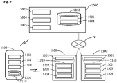
- FIG. 2 depicts schematically an example of the claimed system for opening a gate of a public transport station.
- the depicted system comprises a back office 1000, a mobile device 1100 of a passenger, at least two gates 1200, 1300 of a public transport station, and a network N which connects the back office 1000 and gate control devices 1210, 1310.
- the two gates 1200, 1300 are each equipped with a transmitter 1201, 1301 and a gate control device 1210, 1310. It may also be possible that the transmitter 1201, 1301 is included in the gate control device 1210, 1310. Alternatively, it may also be possible that the gate control device 1210, 1310 is located remote from the gate.
- Each of the two gate control devices 1210, 1310 comprises a signal receiver unit 1202, 1302, a signal analyser unit 1203, 1303 and a gate opening control unit 1204, 1304.
- the passenger's mobile device 1100 comprises a transmitter signal receiver unit 1101, a mobile device data storage unit 1110, in which a gate identifier list 1104 is stored, a validation signal generator unit 1102 and a validation signal transmitter unit 1103.
- the back office 1000 includes a back-office data storage unit 1010, in which a gate identifier table 1001 and a user status management table 1002 is stored, as well as a user status management unit 1003, a journey history calculation unit 1004 and a fare calculation unit 1005.
- the user status management table 1002 may be stored in the passenger's mobile device 1100.
- the back office 1000 may be connected to the gate control devices 1210, 1310 via a wireless data connection such as the internet or a wireless local area network.
- the back office 1000 may be connected to the mobile device 1100 via a mobile network.
- the transmitters 1201, 1301 installed at the gates 1200, 1300 may emit transmitter signals via a radio signal in a predefined range around the transmitter 1201, 1301 periodically and/or constantly. Each transmitter signal may include a gate identifier clearly identifying the gate 1200, 1300 at which the transmitter 1201, 1301 is installed.
- the transmitter signal receiver unit 1101 of the mobile device 1100 may receive the transmitter signals including the gate identifiers from the two transmitters 1201, 1301, and may write the gate identifiers included in the two transmitter signals together with a time stamp in a gate identifier list 1104, which is stored in the mobile device data storage unit 1110.
- An exemplary structure of a gate identifier list 1104 will be described below in connection with Fig. 3c .
- the validation signal generator unit 1102 of the passenger's mobile device 1100 may select one of the received transmitter signals stored in the gate identifier list 1104 based on a signal characteristic such as the signal strength and/or the signal frequency of the received transmitter signals. Subsequently, the validation signal generator unit 1102 may read the gate identifier of the selected signal from the gate identifier list 1104 and generate a validation signal including the gate identifier of the selected transmitter signal and a user identifier of the passenger's mobile device 1100. In a next step, the validation signal transmitter unit 1103 of the passenger's mobile device 1100 may transmit the generated validation signal to the gate control devices 1210, 1310 via the signal receiver unit 1202, 1302 of each gate control device 1210, 1310.
- the validation signal transmitter unit 1103 may transmit the validation signal via a wireless communication such as a wireless local area network, Bluetooth low energy (Bluetooth is a registered trademark), ultra-wideband and the like.
- the signal analyser unit 1203, 1303 of each gate control device 1210, 1310 may compare the gate identifier included in the received validation signal with a gate identifier of the gate 1200, 1300 controlled by the respective gate control device 1210, 1310. If the signal analyser unit 1203, 1303 of a gate control device 1210, 1310 determines that the received gate identifier matches to the gate identifier of the gate 1200, 1300 controlled by the gate control device 1210, 1310, the respective gate control unit 1210, 1310 may transmit a user status request to the user status management unit 1003 of the back office 100.
- the user status management unit 1003 When the user status management unit 1003 receives a user status request from the gate control device 1210, 1310 controlling the gate to be opened, it may read a previous user status from the user status management table 1002 based on the user identifier included in the received status request.
- An exemplary structure of a user status management table 1002 will be described below in connection with Fig. 3b .
- the user status management unit 1003 may then determine a current user status based on the previous user status, and transmit the current user status to the gate control device from which it has received the user status request.
- the signal receiver unit 1103 of the respective gate control device may receive the current user status based on which the signal analyser unit 1203 of the gate control device 1210, 1310 may determine an opening direction of the gate 1200, 1300.
- the gate opening control unit 1204, 1304 of the gate control device 1210, 1310 may control the gate 1200, 1300 to open in the determined direction.
- the user status management unit 1003 of the back office 1000 may determine a current location of a user 100 based on the gate identifier included in the received user status request.
- the current location of the user 100 can be determined by determining the location of the gate 1200, 1300 that the user 100 has just passed using the gate identifier table 1001 stored in the back-office data storage unit 1010, in which each gate identifier may be listed in connection with the location of the corresponding gate.
- An exemplary structure of a gate identifier table 1001 will be described below in connection with Fig. 3a .
- the user status management unit 1003 may update the user status management table 1002 according to the determined current user status and the determined current location of the user 100.
- the depicted back office includes a journey history calculation unit 1003 and a fare calculation unit 1005.
- the journey history calculation unit 1003 may calculate the journey of a passenger from a travel start station and a travel end station.
- the travel start station may be the station of public transport, such as a bus station or a train station, where a passenger started a passenger journey and correspondingly the travel end station may be the station of public transport where a passenger ended a passenger journey. Based on a travel start station and a travel end station, a total distance which a passenger travelled during a passenger journey can be determined.
- the fare calculation unit 1005 may calculate a corresponding fare that has to be paid by the passenger for the use of means of public transport in order to get from the travel start station to the travel end station according to the distance between the travel start station and the travel end station calculated by the journey history calculation unit 1004.
- FIG 3a shows an example of a gate identifier table 1001.
- the gate identifier table may preferably be configured to store a gate identifier corresponding to a location of the gate 1200, 1300 identified by the gate identifier.
- gate identifiers Gate ID
- the gate identifier table 1001 indicates that the gates having the Gate IDs 01000 and 01001 are located at Station A. and the gates having the Gate IDs 02000 to 02002 are located at Station B.
- Figure 3b shows an example of a user status management table 1002.
- the user status management table 1002 may preferably be configured to store a user identifier of each passenger's mobile device, a location of a user, a time stamp indicating the time of determining the location of the user and the user status.
- a user identifier of each passenger's mobile device e.g., a location of a user
- a time stamp indicating the time of determining the location of the user and the user status.
- the user status management unit 1003 may determine that User A, having a previous user status "In", is located outside of Station A if he/she passes one of the gates with the gate IDs 01000 and 01001. Accordingly, the user status management unit 1003 may determine that User B is located outside of Station B if he/she passes one of the gates having the Gate IDs 02000 to 02003.
- the user status management unit 1003 may determine that User C is located inside Station A if he/she passes one of the gates with the Gate IDs 01000 and 01001, and that User C is located inside Station B if he/she passes one of the gates with the Gate IDs 02000 to 02002.
- Figure 3c shows an example of a gate identifier list showing received gate identifiers each provided with a time stamp.
- the first column of the depicted exemplary gate identifier list 1104 indicates the time stamps at which the Gate IDs listed in the second column are received.
- the third column indicates the RSSI value of the received transmitter signals.
- the gate having the Gate ID 1001 is closer to the user reaching the gates of Station A, since the corresponding RSSI value of the transmitter signal received by the user's mobile device is higher (closer to 0 dBm).
- the user's mobile device may select this transmitter signal and transmit a validation signal including the Gate ID 1001 to the gate control devices of the two gates of Station A.
- the gate control device connected to the gate with the gate ID 1001 may control the gate to open.
- FIG. 4 shows schematically an example of a signal flow between devices of the claimed system.
- the respective gate IDs (gate ID(A), gate ID(B)) are transmitted from gate A and gate B to the mobile device, which receives both gate IDs and selects the gate ID(B) to generate a validation signal, since Gate B is closer to the mobile device.
- the generated validation signal including a User ID and the Gate ID(B) is transmitted from the mobile device to both gates, each comprising a gate control device.
- Both gate control devices compare the Gate ID(B) included in the validation signal with the Gate ID of their gate. Since the received Gate ID(B) matches to the Gate ID of Gate B, the gate control device of Gate B transmits a user status request including the received User ID to the back office. The back office checks the previous user status, determines a current user status and transmits the current user status to the control device of Gate B.
- the control device of Gate B then controls the Gate B to open the gate.
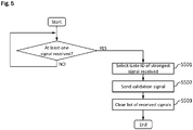
- FIG. 5 shows a flow chart that exemplary illustrates a selection of a gate identifier by a passenger's mobile device depending on the signal strength of the received transmitter signals.
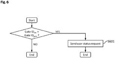
- FIG. 6 shows a flow chart that exemplary illustrates analysing of a validation signal by a plurality of gate control devices after receiving the validation signal.
- each gate control device compares the gate identifier included in the received validation signal Gate ID rec with the gate identifier Gate ID gate of the gate to which a gate control device is connected. If both gate identifiers do not match, the respective gate control device may finish the process. If both gate identifiers do match, the respective gate control device may send a user status request to the back office (S601) before the process is finished.
- FIG. 7 shows a flow chart that exemplary illustrates determining a user status by a back office.
- a user status management unit of the back office firstly checks whether any user status assigned to the received user identifier is stored in a user status management table. If no user status is available the current user status may be determined to be "inside” (S701). If the latest user status stored in the user status management table states “inside”, the current user status may be determined to be "outside” (S703), otherwise the current user status may be determined to be "inside” (S702). In the following step S704, the current location of the user may be determined and then the user status management table may be updated (S705) by the user status management unit before the process is finished.
- Figure 8 shows a flow chart that exemplary illustrates a process of controlling gate opening according to a user status by a gate control device.
- the gate control device checks whether the current user status of the user intending to pass the gate is stated to be "inside" or "IN” (instead of "OUT"). If this is the case, the gate control device controls the gate to open in the entrance direction (S802), otherwise the gate control device controls the gate to open in the exit direction (S801) before it finishes the process. It other words, the current user status may preferably be updated before the passenger passes the gate. In even other words, a decision of opening the gate may preferably always follow after an updating of the passenger's status.
- the current user status of a passenger who will be approaching a gate for going out from the station will be "OUT” so that the gate opens in the exit direction and a passenger who will be approaching a gate for entering into the station will be "IN” so that the gate opens in the entrance direction.
- the above preferred example of the opening directions may also be vice versa without departing from the principle technical idea explained herein.
- the present disclosure provides a system, a method and a computer program product for automatically opening a gate of a public transport station.
- the disclosed subject matter is part of a mobile computer based public transportation management system and allows for improving the flow of passengers through a station, inter alia, by optimizing the route of a passenger equipped with a mobile device (user) within the station without increasing the computational effort of an existing system.
- the disclosed subject matter offers the advantage that available technology, which is already used in current mobile computer based public transportation management systems can be additionally used to improve the passenger flow. Thus, no further measuring equipment is needed. By determining the door opening direction on the basis of data already stored in the existing system, the user status does not have to be calculated, so that no additional computing effort is required.
- the present disclosure may be embodied as a method, an apparatus (including a device, machine, system, computer program product, and/or any other apparatus), or a combination of the foregoing.
- embodiments of the present disclosure may take the form of an entirely hardware embodiment, an entirely software embodiment (including firmware, resident software, micro-code, etc.), or an embodiment combining software and hardware aspects that may generally be referred to herein as a "system".
- embodiments of the present disclosure may take the form of a computer program product on a computer-readable medium having computer-executable program code embodied in the medium.
- arrows may be used in drawings to represent communication, transfer, or other activity involving two or more entities. Double-ended arrows generally indicate that activity may occur in both directions (e.g., a command/request in one direction with a corresponding reply back in the other direction, or peer-to-peer communications initiated by either entity), although in some situations, activity may not necessarily occur in both directions.
- Single-ended arrows generally may indicate activity exclusively or predominantly in one direction, although it should be noted that, in certain situations, such directional activity actually may involve activities in both directions (e.g., a message from a sender to a receiver and an acknowledgement back from the receiver to the sender, or establishment of a connection prior to a transfer and termination of the connection following the transfer).
- directional activity actually may involve activities in both directions (e.g., a message from a sender to a receiver and an acknowledgement back from the receiver to the sender, or establishment of a connection prior to a transfer and termination of the connection following the transfer).
- the type of arrow used in a particular drawing to represent a particular activity is exemplary and should not be seen as limiting.
- the computer-executable program code may be provided to a processor of a general purpose computer, special purpose computer, or other programmable data processing apparatus to produce a particular machine, such that the program code, which executes via the processor of the computer or other programmable data processing apparatus, create means for implementing the functions/acts/outputs specified in the flowchart, block diagram block or blocks, figures, and/or written description.
- These computer-executable program code may also be stored in a computer-readable memory that can direct a computer or other programmable data processing apparatus to function in a particular manner, such that the program code stored in the computer readable memory produce an article of manufacture including instruction means which implement the function/act/output specified in the flowchart, block diagram block(s), figures, and/or written description.
- the computer-executable program code may also be loaded onto a computer or other programmable data processing apparatus to cause a series of operational steps to be performed on the computer or other programmable apparatus to produce a computer-implemented process such that the program code which executes on the computer or other programmable apparatus provides steps for implementing the functions/acts/outputs specified in the flowchart, block diagram block(s), figures, and/or written description.
- computer program implemented steps or acts may be combined with operator or human implemented steps or acts in order to carry out an embodiment.
- a device may include, without limitation, a bridge, router, bridge-router (brouter), switch, node, server, computer, appliance, or other type of device.
- Such devices typically include one or more network interfaces for communicating over a communication network and a processor (e.g., a microprocessor with memory and other peripherals and/or application-specific hardware) configured accordingly to perform device functions.
- Communication networks generally may include public and/or private networks; may include local-area, wide-area, metropolitan-area, storage, and/or other types of networks; and may employ communication technologies including, but in no way limited to, analog technologies, digital technologies, optical technologies, wireless technologies (e.g., Bluetooth (registered trademark)), networking technologies, and internetworking technologies.
- communication technologies including, but in no way limited to, analog technologies, digital technologies, optical technologies, wireless technologies (e.g., Bluetooth (registered trademark)), networking technologies, and internetworking technologies.
- devices may use communication protocols and messages (e.g., messages created, transmitted, received, stored, and/or processed by the device), and such messages may be conveyed by a communication network or medium.
- communication protocols and messages e.g., messages created, transmitted, received, stored, and/or processed by the device
- a communication message generally may include, without limitation, a frame, packet, datagram, user datagram, cell, or other type of communication message.
- references to specific communication protocols are exemplary, and it should be understood that alternative embodiments may, as appropriate, employ variations of such communication protocols (e.g., modifications or extensions of the protocol that may be made from time-to-time) or other protocols either known or developed in the future.
- logic flows may be described herein to demonstrate various aspects and should not be construed to limit the disclosure to any particular logic flow or logic implementation.
- the described logic may be partitioned into different logic blocks (e.g., programs, modules, functions, or subroutines) without changing the overall results.
- logic elements may be added, modified, omitted, performed in a different order, or implemented using different logic constructs (e.g., logic gates, looping primitives, conditional logic, and other logic constructs) without changing the overall results.
- logic constructs e.g., logic gates, looping primitives, conditional logic, and other logic constructs
- the present disclosure may be embodied in many different forms, including, but in no way limited to, computer program logic for use with a processor (e.g., a microprocessor, microcontroller, digital signal processor, or general purpose computer), programmable logic for use with a programmable logic device (e.g., a Field Programmable Gate Array (FPGA) or other PLD), discrete components, integrated circuitry (e.g., an Application Specific Integrated Circuit (ASIC)), or any other means including any combination thereof
- Computer program logic implementing some or all of the described functionality is typically implemented as a set of computer program instructions that is converted into a computer executable form, stored as such in a computer readable medium, and executed by a microprocessor under the control of an operating system.
- Hardware-based logic implementing some or all of the described functionality may be implemented using one or more appropriately configured FPGAs.
- Computer program logic implementing all or part of the functionality previously described herein may be embodied in various forms, including, but in no way limited to, a source code form, a computer executable form, and various intermediate forms (e.g., forms generated by an assembler, compiler, linker, or locator).
- Source code may include a series of computer program instructions implemented in any of various programming languages (e.g., an object code, an assembly language, or a high-level language such as Fortran, C, C++, JAVA, or HTML) for use with various operating systems or operating environments.
- the source code may define and use various data structures and communication messages.
- the source code may be in a computer executable form (e.g., via an interpreter), or the source code maybe converted (e.g., via a translator, assembler, or compiler) into a computer executable form.
- Computer-executable program code for carrying out operations of embodiments of the present disclosure may be written in an object oriented, scripted or unscripted programming language such as Java, Perl, Smalltalk, C++, or the like.
- the computer program code for carrying out operations of embodiments may also be written in conventional procedural programming languages, such as the "C" programming language or similar programming languages.
- Computer program logic implementing all or part of the functionality previously described herein may be executed at different times on a single processor (e.g., concurrently) or may be executed at the same or different times on multiple processors and may run under a single operating system process/thread or under different operating system processes/threads.
- computer process may refer generally to the execution of a set of computer program instructions regardless of whether different computer processes are executed on the same or different processors and regardless of whether different computer processes run under the same operating system process/thread or different operating system processes/threads.
- the computer program may be fixed in any form (e.g., source code form, computer executable form, or an intermediate form) either permanently or transitorily in a tangible storage medium, such as a semiconductor memory device (e.g., a RAM, ROM, PROM, EEPROM, or Flash-Programmable RAM), a magnetic memory device (e.g., a diskette or fixed disk), an optical memory device (e.g., a CD-ROM), a PC card (e.g., PCMCIA card), or other memory device.
- a semiconductor memory device e.g., a RAM, ROM, PROM, EEPROM, or Flash-Programmable RAM
- a magnetic memory device e.g., a diskette or fixed disk
- an optical memory device e.g., a CD-ROM
- PC card e.g., PCMCIA card
- the computer program may be fixed in any form in a signal that is transmittable to a computer using any of various communication technologies, including, but in no way limited to, analog technologies, digital technologies, optical technologies, wireless technologies (e.g., Bluetooth (registered trademark)), networking technologies, and internetworking technologies.
- various communication technologies including, but in no way limited to, analog technologies, digital technologies, optical technologies, wireless technologies (e.g., Bluetooth (registered trademark)), networking technologies, and internetworking technologies.
- the computer program may be distributed in any form as a removable storage medium with accompanying printed or electronic documentation (e.g., shrink wrapped software), preloaded with a computer system (e.g., on system ROM or fixed disk), or distributed from a server or electronic bulletin board over the communication system (e.g., the Internet or World Wide Web).
- a computer system e.g., on system ROM or fixed disk
- a server or electronic bulletin board over the communication system (e.g., the Internet or World Wide Web).
- Hardware logic including programmable logic for use with a programmable logic device
- implementing all or part of the functionality previously described herein may be designed using traditional manual methods, or may be designed, captured, simulated, or documented electronically using various tools, such as Computer Aided Design (CAD), a hardware description language (e.g., VHDL or AHDL), or a PLD programming language (e.g., PALASM, ABEL, or CUPL).
- CAD Computer Aided Design
- a hardware description language e.g., VHDL or AHDL
- PLD programming language e.g., PALASM, ABEL, or CUPL
- the computer readable medium may be, for example but not limited to, an electronic, magnetic, optical, electromagnetic, infrared, or semiconductor system, apparatus, device, or medium.
- the computer readable medium include, but are not limited to, an electrical connection having one or more wires or other tangible storage medium such as a portable computer diskette, a hard disk, a random access memory (RAM), a read-only memory (ROM), an erasable programmable read-only memory (EPROM or Flash memory), a compact disc read-only memory (CD-ROM), or other optical or magnetic storage device.
- a portable computer diskette a hard disk
- RAM random access memory
- ROM read-only memory
- EPROM or Flash memory erasable programmable read-only memory
- CD-ROM compact disc read-only memory
- Programmable logic may be fixed either permanently or transitorily in a tangible storage medium, such as a semiconductor memory device (e.g., a RAM, ROM, PROM, EEPROM, or Flash-Programmable RAM), a magnetic memory device (e.g., a diskette or fixed disk), an optical memory device (e.g., a CD-ROM), or other memory device.
- a semiconductor memory device e.g., a RAM, ROM, PROM, EEPROM, or Flash-Programmable RAM
- a magnetic memory device e.g., a diskette or fixed disk
- an optical memory device e.g., a CD-ROM
- the programmable logic may be fixed in a signal that is transmittable to a computer using any of various communication technologies, including, but in no way limited to, analog technologies, digital technologies, optical technologies, wireless technologies (e.g., Bluetooth), networking technologies, and internetworking technologies.
- various communication technologies including, but in no way limited to, analog technologies, digital technologies, optical technologies, wireless technologies (e.g., Bluetooth), networking technologies, and internetworking technologies.
- the programmable logic may be distributed as a removable storage medium with accompanying printed or electronic documentation (e.g., shrink wrapped software), preloaded with a computer system (e.g., on system ROM or fixed disk), or distributed from a server or electronic bulletin board over the communication system (e.g., the Internet or World Wide Web).
- a computer system e.g., on system ROM or fixed disk
- a server or electronic bulletin board over the communication system
- some aspects may be implemented as a combination of both software (e.g., a computer program product) and hardware. Still other embodiments of the may be implemented as entirely hardware, or entirely software.
Landscapes
- Physics & Mathematics (AREA)
- General Physics & Mathematics (AREA)
- Engineering & Computer Science (AREA)
- Computer Security & Cryptography (AREA)
- Computer Networks & Wireless Communication (AREA)
- Signal Processing (AREA)
- Business, Economics & Management (AREA)
- Finance (AREA)
- Aviation & Aerospace Engineering (AREA)
- Devices For Checking Fares Or Tickets At Control Points (AREA)
- Time Recorders, Dirve Recorders, Access Control (AREA)
Priority Applications (4)
| Application Number | Priority Date | Filing Date | Title |
|---|---|---|---|
| EP21164341.6A EP4064231A1 (fr) | 2021-03-23 | 2021-03-23 | Système, procédé et produit programme informatique pour l'ouverture automatique d'un portail d'une station de transport public |
| PCT/EP2022/057072 WO2022200185A1 (fr) | 2021-03-23 | 2022-03-17 | Système, procédé et produit-programme informatique permettant d'ouvrir automatiquement une porte d'une station de transports publics |
| US18/279,244 US20240153330A1 (en) | 2021-03-23 | 2022-03-17 | System, Method and Computer Program Product For Automatically Opening a Gate of a Public Transport Station |
| JP2023543204A JP2024502899A (ja) | 2021-03-23 | 2022-03-17 | 公共交通機関のゲートを自動的に開放するためのシステム、方法およびコンピュータプログラム製品 |
Applications Claiming Priority (1)
| Application Number | Priority Date | Filing Date | Title |
|---|---|---|---|
| EP21164341.6A EP4064231A1 (fr) | 2021-03-23 | 2021-03-23 | Système, procédé et produit programme informatique pour l'ouverture automatique d'un portail d'une station de transport public |
Publications (1)
| Publication Number | Publication Date |
|---|---|
| EP4064231A1 true EP4064231A1 (fr) | 2022-09-28 |
Family
ID=75203033
Family Applications (1)
| Application Number | Title | Priority Date | Filing Date |
|---|---|---|---|
| EP21164341.6A Pending EP4064231A1 (fr) | 2021-03-23 | 2021-03-23 | Système, procédé et produit programme informatique pour l'ouverture automatique d'un portail d'une station de transport public |
Country Status (4)
| Country | Link |
|---|---|
| US (1) | US20240153330A1 (fr) |
| EP (1) | EP4064231A1 (fr) |
| JP (1) | JP2024502899A (fr) |
| WO (1) | WO2022200185A1 (fr) |
Citations (4)
| Publication number | Priority date | Publication date | Assignee | Title |
|---|---|---|---|---|
| EP2991041A2 (fr) * | 2014-08-25 | 2016-03-02 | Accenture Global Services Limited | Communication à base de distance courte sécurisée et système de contrôle d'accès |
| EP3045931A1 (fr) | 2015-01-14 | 2016-07-20 | Tektronix, Inc. | Mécanisme permettant de déterminer un emplacement historique par l'intermédiaire de prédicteurs historiques multiples |
| US20190122475A1 (en) * | 2017-10-25 | 2019-04-25 | Cubic Corporation | Triggered neural gate interface |
| US20200336879A1 (en) * | 2016-05-17 | 2020-10-22 | Amtech Systems, LLC | Vehicle tracking system using smart-phone as active transponder |
-
2021
- 2021-03-23 EP EP21164341.6A patent/EP4064231A1/fr active Pending
-
2022
- 2022-03-17 US US18/279,244 patent/US20240153330A1/en active Pending
- 2022-03-17 WO PCT/EP2022/057072 patent/WO2022200185A1/fr active Application Filing
- 2022-03-17 JP JP2023543204A patent/JP2024502899A/ja active Pending
Patent Citations (4)
| Publication number | Priority date | Publication date | Assignee | Title |
|---|---|---|---|---|
| EP2991041A2 (fr) * | 2014-08-25 | 2016-03-02 | Accenture Global Services Limited | Communication à base de distance courte sécurisée et système de contrôle d'accès |
| EP3045931A1 (fr) | 2015-01-14 | 2016-07-20 | Tektronix, Inc. | Mécanisme permettant de déterminer un emplacement historique par l'intermédiaire de prédicteurs historiques multiples |
| US20200336879A1 (en) * | 2016-05-17 | 2020-10-22 | Amtech Systems, LLC | Vehicle tracking system using smart-phone as active transponder |
| US20190122475A1 (en) * | 2017-10-25 | 2019-04-25 | Cubic Corporation | Triggered neural gate interface |
Also Published As
| Publication number | Publication date |
|---|---|
| WO2022200185A1 (fr) | 2022-09-29 |
| JP2024502899A (ja) | 2024-01-23 |
| US20240153330A1 (en) | 2024-05-09 |
Similar Documents
| Publication | Publication Date | Title |
|---|---|---|
| CN104067642B (zh) | 用于控制便携式无线用户设备对安全消息的传输和/或接收的方法和装置 | |
| US10953901B2 (en) | Train operation control system and train operation control method | |
| US20180275648A1 (en) | System and method for automatic passenger sharing among vehicles | |
| KR102317461B1 (ko) | 딥러닝 기반 주차장 이용 패턴 분석을 통한 지능형 주차 안내 서비스 시스템 및 방법 | |
| US20170124871A1 (en) | System and method for vehicle data communication | |
| GB2527499A (en) | Travel data of transport system users | |
| CN112584317A (zh) | 对移动入口点的触觉引导和导航 | |
| US10154393B2 (en) | Method, motor vehicle, and system for determining a transmission path | |
| EP4064231A1 (fr) | Système, procédé et produit programme informatique pour l'ouverture automatique d'un portail d'une station de transport public | |
| CN113780654A (zh) | 地铁站中对乘客行走指引的方法、装置、设备及存储介质 | |
| CN111163453A (zh) | 一种应急车辆响应的方法和设备 | |
| CN109690645B (zh) | 用于感测机动车的周围环境的方案 | |
| WO2019130300A1 (fr) | Procédé, dispositif et système de commande de feu de signalisation faisant appel à des détecteurs virtuels | |
| WO2019008957A1 (fr) | Procédé et appareil pour estimer la capacité d'une zone prédéterminée d'un véhicule | |
| KR101844323B1 (ko) | 대중 교통 수단의 하차 정보를 제공하는 하차 정보 제공 서버, 방법 및 사용자 단말 | |
| JP2005333225A (ja) | 通信システム、通信機およびセンター装置 | |
| CN111741051B (zh) | 交通工具满载率确定方法、装置、存储介质及电子装置 | |
| CN115966098A (zh) | 一种预测公交车到站时间的方法及设备 | |
| KR102186783B1 (ko) | 내비게이션 장치, 그 방법 및 컴퓨터 프로그램이 기록된 기록매체 | |
| US10546307B2 (en) | Method, apparatuses, and computer program products for automatically detecting levels of user dissatisfaction with transportation routes | |
| KR101428513B1 (ko) | 차량이 수집한 상태정보를 무선 기지국으로 전달하기 위한 정보전달 장치 및 그 방법 | |
| KR100924829B1 (ko) | 노선 안내시스템 및 방법 | |
| KR20220043469A (ko) | 이용자 참여형 노선정보 서비스장치 및 그 장치의 구동방법, 그리고 컴퓨터 판독가능 기록매체 | |
| CN107843906B (zh) | 移动终端的导航定位方法及其系统 | |
| CN117191067B (zh) | 出行路线规划方法、装置、电子设备和计算机可读介质 |
Legal Events
| Date | Code | Title | Description |
|---|---|---|---|
| PUAI | Public reference made under article 153(3) epc to a published international application that has entered the european phase |
Free format text: ORIGINAL CODE: 0009012 |
|
| STAA | Information on the status of an ep patent application or granted ep patent |
Free format text: STATUS: REQUEST FOR EXAMINATION WAS MADE |
|
| 17P | Request for examination filed |
Effective date: 20210715 |
|
| AK | Designated contracting states |
Kind code of ref document: A1 Designated state(s): AL AT BE BG CH CY CZ DE DK EE ES FI FR GB GR HR HU IE IS IT LI LT LU LV MC MK MT NL NO PL PT RO RS SE SI SK SM TR |
|
| STAA | Information on the status of an ep patent application or granted ep patent |
Free format text: STATUS: EXAMINATION IS IN PROGRESS |