EP4064104A2 - Procédé assisté par ordinateur d'évaluation de la résistance pour composants mécaniques et composant mécanique - Google Patents
Procédé assisté par ordinateur d'évaluation de la résistance pour composants mécaniques et composant mécanique Download PDFInfo
- Publication number
- EP4064104A2 EP4064104A2 EP22163880.2A EP22163880A EP4064104A2 EP 4064104 A2 EP4064104 A2 EP 4064104A2 EP 22163880 A EP22163880 A EP 22163880A EP 4064104 A2 EP4064104 A2 EP 4064104A2
- Authority
- EP
- European Patent Office
- Prior art keywords
- component
- strength
- computer
- implemented method
- values
- Prior art date
- Legal status (The legal status is an assumption and is not a legal conclusion. Google has not performed a legal analysis and makes no representation as to the accuracy of the status listed.)
- Withdrawn
Links
Images
Classifications
-
- G—PHYSICS
- G06—COMPUTING OR CALCULATING; COUNTING
- G06F—ELECTRIC DIGITAL DATA PROCESSING
- G06F30/00—Computer-aided design [CAD]
- G06F30/20—Design optimisation, verification or simulation
- G06F30/23—Design optimisation, verification or simulation using finite element methods [FEM] or finite difference methods [FDM]
-
- G—PHYSICS
- G06—COMPUTING OR CALCULATING; COUNTING
- G06F—ELECTRIC DIGITAL DATA PROCESSING
- G06F30/00—Computer-aided design [CAD]
- G06F30/10—Geometric CAD
- G06F30/15—Vehicle, aircraft or watercraft design
-
- G—PHYSICS
- G06—COMPUTING OR CALCULATING; COUNTING
- G06F—ELECTRIC DIGITAL DATA PROCESSING
- G06F30/00—Computer-aided design [CAD]
- G06F30/10—Geometric CAD
- G06F30/17—Mechanical parametric or variational design
-
- G—PHYSICS
- G01—MEASURING; TESTING
- G01M—TESTING STATIC OR DYNAMIC BALANCE OF MACHINES OR STRUCTURES; TESTING OF STRUCTURES OR APPARATUS, NOT OTHERWISE PROVIDED FOR
- G01M17/00—Testing of vehicles
- G01M17/08—Railway vehicles
-
- G—PHYSICS
- G06—COMPUTING OR CALCULATING; COUNTING
- G06F—ELECTRIC DIGITAL DATA PROCESSING
- G06F17/00—Digital computing or data processing equipment or methods, specially adapted for specific functions
- G06F17/10—Complex mathematical operations
- G06F17/11—Complex mathematical operations for solving equations, e.g. nonlinear equations, general mathematical optimization problems
- G06F17/12—Simultaneous equations, e.g. systems of linear equations
-
- G—PHYSICS
- G06—COMPUTING OR CALCULATING; COUNTING
- G06F—ELECTRIC DIGITAL DATA PROCESSING
- G06F2111/00—Details relating to CAD techniques
- G06F2111/10—Numerical modelling
-
- G—PHYSICS
- G06—COMPUTING OR CALCULATING; COUNTING
- G06F—ELECTRIC DIGITAL DATA PROCESSING
- G06F2119/00—Details relating to the type or aim of the analysis or the optimisation
- G06F2119/02—Reliability analysis or reliability optimisation; Failure analysis, e.g. worst case scenario performance, failure mode and effects analysis [FMEA]
-
- G—PHYSICS
- G06—COMPUTING OR CALCULATING; COUNTING
- G06F—ELECTRIC DIGITAL DATA PROCESSING
- G06F2119/00—Details relating to the type or aim of the analysis or the optimisation
- G06F2119/04—Ageing analysis or optimisation against ageing
-
- G—PHYSICS
- G06—COMPUTING OR CALCULATING; COUNTING
- G06F—ELECTRIC DIGITAL DATA PROCESSING
- G06F2119/00—Details relating to the type or aim of the analysis or the optimisation
- G06F2119/14—Force analysis or force optimisation, e.g. static or dynamic forces
Definitions
- Vehicle components in particular components of undercarriages of rail vehicles, are excited to vibrate by contact-mechanical conditions between wheels and roadways or tracks, which often extend over a large frequency range. Sudden loads and states of resonance occur, which can lead to severe material stress and possibly to serious damage to the vehicle components. Material fatigue and component failure can occur.
- chassis of rail vehicles are in particular Add-on parts (e.g. brake or antenna mounts, etc.), but also chassis frames, wheel bearings, etc. cyclically highly stressed components.
- EN 13749 which refers to the specification method for strength requirements for chassis frames of rail vehicles
- a method is again disclosed in which, to simulate the vibration behavior of a component, quasi-static accelerations are applied to the component or to mass points of the component are applied.
- the component is designed with loads from EN 13749. This design is checked by means of operational measurements.
- a strength evaluation method in which spectral power densities are determined from measured accelerations and applied to a component, is shown in EN 61373, which refers to vibration and shock tests on rail vehicles, especially add-on parts.
- this approach has the disadvantage that application of the strength assessment method often leads to oversizing of components, since this strength assessment method generally relates to rather light electronic components.
- the invention is therefore based on the object of specifying a method that has been further developed compared to the prior art, which enables a strength assessment of components that are subject to cyclic loads to be carried out with a high degree of accuracy, a low susceptibility to errors, taking into account long load sequences and at the same time an efficient utilization of internal processes of a computer.
- the modal behavior of the first component or a plurality of components is taken into account by means of the method according to the invention. Due to a moderate utilization of a computer processor (or a plurality of processors or processor cores) by the method according to the invention, strength parameters can be determined for the entire first component or for the entire assembly and not just sections thereof.
- the method according to the invention also has the advantage that long operating sequences of the first component or assembly can be evaluated due to the moderate utilization of the computer mentioned. This makes it possible to carry out entire operational measurements on a rail vehicle for which several thousand kilometers can be covered, in order to be able to identify critical vibration excitation sequences on the first component or assembly as well as critical vibration behavior.
- linear superposition is particularly advantageous due to its scalability, because result values with several thousand time steps can be determined at several tens of thousands of evaluation points. At the same time, linear superposition also contributes to high computing efficiency, since it is a linear solution principle.
- the first component or assembly can be designed for the expected loads. Subsequent constructive changes (e.g. as a result of an operational measurement run and corresponding operational measurements) can thus be avoided.
- One purpose pursued with the method according to the invention is to increase component safety and/or component service life.
- time steps are removed from the time-dependent, modal functions, in which amplitudes of a vibration described by means of the time-dependent, modal functions, at least of the first component, are less than or equal to a defined portion of a limit amplitude of the vibration.
- Vibration properties of a chassis component of a rail vehicle can already be described with sufficient accuracy using a few hundred natural modes. With the number of 10 4 or less modal degrees of freedom of movement, usual excitation frequency ranges are well covered and at the same time there is a significant reduction in computing time. Furthermore, the result values of the strength parameters are reduced to a number that enables an effective and rapid machine evaluation with little use of resources.
- the transient excitation on at least the first component is determined from acceleration measurements using sensors.
- the transient excitation on at least the first component is determined from a dynamic multi-body simulation.
- a preferred solution is achieved if displacements are determined as transient result values for strength parameters at least of the first component.
- stresses are determined as transient result values for strength parameters at least for the first component.
- the result values can be compared with corresponding nominal and/or limit values (for example from a standard), whereby Utilization levels of at least the first component or assembly can be determined.
- a design and/or testing of the first component or assembly for fatigue strength is achieved when the result values in a fatigue strength assessment are compared with the nominal strength values and/or the strength limit values for at least the first component.
- a fatigue strength design and/or testing of the first component or assembly is achieved when the result values in a fatigue strength analysis are compared with the nominal strength values and/or the strength limit values for at least the first component.
- a mechanical component is constructed, which is designed as a chassis component of a rail vehicle.
- chassis component is designed as a chassis frame.
- chassis component is designed as a wheel bearing housing or wheel set bearing housing. It is also advantageous if the chassis component is designed as an add-on part or console.
- the running gear frame, the wheel bearing housing (or wheel set bearing housing) and the add-on part or console are large, heavily loaded components of the rail vehicle, which can also be subject to shock and/or cyclic loads.
- a construction of these components using the method according to the invention is particularly effective due to the high level of component reliability that can be achieved with at the same time low processor utilization.
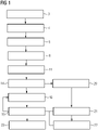
- a computer-implemented, modal-transient, structural-dynamic strength evaluation method for mechanical components shown as a flowchart, is used for a first component 1 designed as a chassis frame of a chassis of a rail vehicle, parts of which are shown in 3 is shown.
- a linear simulation model is created to determine the stresses in relation to the first component 1, by means of which dynamic mass properties, stiffness properties and damping properties of the first component 1 are defined (modeling 3).
- the mass properties, stiffness properties, and damping properties are concentrated into a mass matrix, a stiffness matrix, and a complete damping matrix. From this, equations of motion are formed and natural modes are determined (natural mode determination 4).
- a differential equation system formed from the simulation model from the equations of motion is solved for the first component 1 using a modal transient simulation method. This results in a reduction 5 from the number of unlimited physical degrees of freedom of the at least first component 1 to a number of 10 4 modal degrees of freedom.
- the reduction 5 is performed by transforming the equations of motion from physical coordinates to modal coordinates.
- a transient displacement excitation is applied to the modeled first component 1 in a first transition region 6 to a second component 2, which as an in 3 shown first wheel set guide bushing 7 is formed applied.
- the first component 1 and the second component 2 are capable of vibrating and the first component 1 becomes one Statistical, time-varying movement prescribed (excitation application 8).
- the transient path excitation is determined from acceleration measurements using acceleration sensors. These acceleration measurements are carried out during test drives on a test rail vehicle, on the test chassis frame of which acceleration sensors are arranged.
- transient displacement excitation is determined from a dynamic multi-body simulation using a computer program product known from the prior art.
- the first transition area 6 between the first component 1 and the second component 2 is a flange-like area of the running gear frame, which adjoins the first wheel set guide bush 7 (see also 3 ).
- the first component 1 it is also conceivable for the first component 1 to be in the form of a wheel bearing housing or wheel set bearing housing, which itself forms a transition area to a first wheel set 9 .
- the first wheel set 9 is regarded as the second component 2 in such a variant.
- the transient travel excitation can be applied, for example, directly to the first wheel set bearing housing, for example in the area of a first wheel set bearing 10 .
- the first component 1 is designed as an add-on part or as a console, which is connected to the chassis frame, for example.
- the transition area between the first component 1 and the chassis frame, which acts as a second component 2 in such a variant, is, for example, a in this variant Bolting area etc. between the add-on part and the chassis frame.
- time steps are removed from the time-dependent, modal functions (emitted), in which the time-dependent, modal functions have no local extreme values and in which amplitudes of a vibration of the first component 1 described by means of the time-dependent, modal functions are less than or equal to a defined proportion of an in 2 illustrated limit amplitude 15 of the oscillation (time step setting 16, see a first time step 17 and a second time step 18, which are shown in 2 shown as removed).
- transient result values for strength parameters of the first component 1 are now determined using a linear superposition principle known from the prior art (result formation 19), with computer processor utilization being reduced due to the linear character of the result formation 19.
- the result values are displacements, but strains and stresses, i.e. stresses on the first component 1, are also determined as result values.
- a number of time steps to be removed can be changed later by the inventive The method is carried out without removing time steps from the time-dependent, modal functions, based on the model formation 3 already carried out, the eigenmode determination 4, the reduction 5, the excitation application 8, the evaluation point formation 11 and the function formation 14 from the verification process pass as described above Principle check result values are formed (check result formation 20), the check result values are compared with the result values (result comparison 21), and an error due to the removal of time steps from the time-dependent, modal functions is determined from the result comparison 21 (error determination 22).
- the time steps that have been removed are gradually reintroduced into the process via the time step setting 16 and, with the reinserted time steps, a new result is formed 19.
- the result values are compared with nominal strength values and strength limit values for the first component 1 . These are nominal strength values and strength limit values from the results of a standardized Wöhler test.
- the strength rating 23 is therefore as Fatigue strength and time or fatigue strength assessment carried out.
- the first component 1 is dimensioned on the basis of the strength assessment 23 .
- a dimensioning and a definition of the geometry is carried out in such a way that mechanical utilization levels of the first component 1 are less than or equal to a utilization limit.
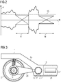
- FIG. 2 shows a diagram which represents a frequency f over a time t.
- the diagram represents a vibration behavior of a first component 1, which is associated with 1 and 3 is described. This vibration behavior is represented by an in 1 method shown analyzed.
- a strength assessment 23 of the first component 1 is carried out on the basis of this vibration behavior.
- a first time step 17 and a second time step 18 are removed from time-dependent, modal functions that describe the vibration behavior.
- a corresponding removal (Omission) will be in a related with 1 described time step setting 16 is carried out because the first time step 17 and the second time step 18 have no local extreme values and in the first time step 17 and the second time step 18 amplitudes of a vibration of the first component 1 described by means of the time-dependent, modal functions are smaller than a defined proportion of a Limit amplitude 15 of the vibration are.
- a section of a running gear of a rail vehicle which has a first component 1 designed as a running gear frame.
- the chassis frame is coupled to wheel sets via wheel set guide bushes, swing arms and wheel set bearings.
- a in 3 visible first swing arm 24 is via a first wheel set guide bush 7 trained second component 2 connected to the chassis frame and a first wheel set bearing 10 with a first wheel set 9.
- the first swing arm 24 acts as a wheel set bearing housing for the first wheel set bearing 10 in an area facing the first wheel set 9 and encasing the first wheel set bearing 10.
- a strength assessment 23 is carried out using a method 1 carried out.
- This strength assessment 23 is used for a first strength assessment point 12 in a flange-like first transition area 6 between the first component 1 and the second component 2, in which a transient displacement excitation is also applied, for a second strength assessment point 13 between a longitudinal member 25 of the chassis frame and a cross member 26 of the chassis frame as well as for further, in 3 carried out not shown strength assessment points.
- Appropriate strength assessment points are to be selected for this on the wheel set bearing housing or on the first swing arm 24 or on the carrier 27 etc. according to an expected mechanical load.
Landscapes
- Physics & Mathematics (AREA)
- Engineering & Computer Science (AREA)
- Geometry (AREA)
- Theoretical Computer Science (AREA)
- General Physics & Mathematics (AREA)
- Computer Hardware Design (AREA)
- General Engineering & Computer Science (AREA)
- Evolutionary Computation (AREA)
- Mathematical Analysis (AREA)
- Pure & Applied Mathematics (AREA)
- Mathematical Optimization (AREA)
- Computational Mathematics (AREA)
- Automation & Control Theory (AREA)
- Aviation & Aerospace Engineering (AREA)
- Testing Of Devices, Machine Parts, Or Other Structures Thereof (AREA)
- Investigating Strength Of Materials By Application Of Mechanical Stress (AREA)
Applications Claiming Priority (1)
| Application Number | Priority Date | Filing Date | Title |
|---|---|---|---|
| ATA50214/2021A AT524877A1 (de) | 2021-03-26 | 2021-03-26 | Computerimplementiertes Festigkeitsbewertungsverfahren für mechanische Bauteile und mechanisches Bauteil |
Publications (2)
| Publication Number | Publication Date |
|---|---|
| EP4064104A2 true EP4064104A2 (fr) | 2022-09-28 |
| EP4064104A3 EP4064104A3 (fr) | 2022-12-14 |
Family
ID=80930245
Family Applications (1)
| Application Number | Title | Priority Date | Filing Date |
|---|---|---|---|
| EP22163880.2A Withdrawn EP4064104A3 (fr) | 2021-03-26 | 2022-03-23 | Procédé assisté par ordinateur d'évaluation de la résistance pour composants mécaniques et composant mécanique |
Country Status (2)
| Country | Link |
|---|---|
| EP (1) | EP4064104A3 (fr) |
| AT (1) | AT524877A1 (fr) |
Family Cites Families (6)
| Publication number | Priority date | Publication date | Assignee | Title |
|---|---|---|---|---|
| US6212486B1 (en) * | 1998-09-17 | 2001-04-03 | Ford Global Technologies, Inc. | Method of identifying critical elements in fatigue analysis with von mises stress bounding and filtering modal displacement history using dynamic windowing |
| US6704664B2 (en) * | 2001-12-18 | 2004-03-09 | Visteon Global Technologies, Inc. | Fatigue sensitivity determination procedure |
| DE10257793A1 (de) * | 2002-12-11 | 2004-07-22 | Daimlerchrysler Ag | Modellbasierter Lebensdauerbeobachter |
| AT514023B1 (de) * | 2013-03-06 | 2015-04-15 | Siemens Ag Oesterreich | Fahrwerk für Schienenfahrzeuge |
| US20160034621A1 (en) * | 2014-08-04 | 2016-02-04 | Livermore Software Technology Corporation | Numerical Simulation Of Crack Propagation Due To Metal Fatigue |
| CN111046600A (zh) * | 2018-10-11 | 2020-04-21 | 株洲中车时代电气股份有限公司 | 一种动态载荷识别方法 |
-
2021
- 2021-03-26 AT ATA50214/2021A patent/AT524877A1/de unknown
-
2022
- 2022-03-23 EP EP22163880.2A patent/EP4064104A3/fr not_active Withdrawn
Non-Patent Citations (3)
| Title |
|---|
| M. SCHMIDT: "ZEVrail", vol. 133, 2009, article "Dynamische Lastannahmen und ermüdungsfeste Auslegung von Trägerstrukturen für Zugsicherungsantennen" |
| P. WOLFSTEINERW. BREUER: "Fatigue assessment of vibrating rail vehicle bogie components under non-Gaussian random excitations using power spectral densities", JOURNAL OF SOUND AND VIBRATION, vol. 332, no. 22, 2013, pages 5867 - 5882, XP028682561, DOI: 10.1016/j.jsv.2013.06.012 |
| Y. LUP. XIANGP. DONGX. ZHANGJ. ZENG: "Analysis of the effects of vibration modes on fatigue damage in high-speed train bogie frames", ENGINEERING FAILURE ANALYSIS, vol. 89, 2018, pages 222 - 241 |
Also Published As
| Publication number | Publication date |
|---|---|
| AT524877A1 (de) | 2022-10-15 |
| EP4064104A3 (fr) | 2022-12-14 |
Similar Documents
| Publication | Publication Date | Title |
|---|---|---|
| EP0554779B1 (fr) | Procédé d'essai des composants d'un véhicule, en particulier la suspension des roues | |
| DE102011053325A1 (de) | Prüfstand für die dynamische Überprüfung einer einzelnen Fahrwerkskomponente oder eines vollständigen Achssystems eines Kraftfahrzeugs, sowie Verfahren zum Überprüfen auf Selbigem | |
| DE102017110228A1 (de) | Verfahren zur Vorhersage von Versagenslasten von Strukturen aus Faserverbundwerkstoffen auf Basis von Schallemissionsdaten | |
| DE102017217561A1 (de) | Verfahren zur Betriebsfestigkeitsanalyse eines Bauteils | |
| Yu et al. | New methodology for determination of load spectra for the vehicle accelerated durability testing associated with the time correlated fatigue damage analysis method | |
| DE102021203266A1 (de) | Verfahren und Fahrzeugsystem zum Bestimmen eines Zustands der Komponenten eines Fahrwerks | |
| EP1534572A1 (fr) | Procede et dispositif de controle de l'etat de mecanismes de deplacement de vehicules | |
| DE4000940A1 (de) | Verfahren und vorrichtung zum pruefen von fahrzeugen | |
| DE102010021643A1 (de) | Verfahren und Vorrichtung zum Bestimmen einer Auslenkung eines Turms | |
| EP1930711B1 (fr) | Procédé d'obtention de données pour l'immatriculation d'un avion | |
| EP4064104A2 (fr) | Procédé assisté par ordinateur d'évaluation de la résistance pour composants mécaniques et composant mécanique | |
| DE102014106701B4 (de) | Verfahren zur Bestimmung einer statischen Biegesteifigkeit eines Objekts aus dynamischen Beschleunigungsmessungen nach einer Schwingungsanregung des Objekts | |
| DE102013105397A1 (de) | Zustandsüberwachung eines Schienenfahrzeugs | |
| DE10252875A1 (de) | Betriebsfestigkeitsprüfung von Bauteilen eines Kraftfahrzeuges | |
| EP3224590B1 (fr) | Procédé de détermination d'un couple de torsion | |
| DE102021131262A1 (de) | Verfahren zum Durchführen einer Betriebsfestigkeitsprüfung und Prüfstandsystem | |
| EP0684465B1 (fr) | Procédé de compression des fonctions charge-temps multiaxiaux mesurées, en particulier pour l'examen de la résistance contre les vibrations de structures | |
| DE102024138536B3 (de) | Verfahren zur simulationsgestützten Omission von Betriebslastsignalen | |
| DE102022210270A1 (de) | Verfahren und Vorrichtung zum Ermitteln einer mechanischen Anregung einer Komponente einer mechanischen Vorrichtung | |
| WO2020094407A1 (fr) | Procédé pour déterminer au moins un paramètre d'état d'un dispositif d'amortissement d'un véhicule automobile | |
| DE102020209184A1 (de) | System zum Überwachen einer Rad-Schienen-Kontaktkraft | |
| DE102015008933A1 (de) | Verfahren zur Betriebsfestigkeitsauslegung eines Rotors einer elektrischen Maschine | |
| DE102013005405A1 (de) | Verfahren und Vorrichtung zur Ermittlung von Akustikeigenschaften eines Fahrzeuginnenraums | |
| DE102017009384A1 (de) | Verfahren zum Testen eines Blechschnitts einer Blechlage für einen Rotor einer elektrischen Maschine | |
| DE102019218996B4 (de) | Verfahren und Vorrichtung zur Ermittlung eines Schädigungszustands von Bauteilen |
Legal Events
| Date | Code | Title | Description |
|---|---|---|---|
| PUAI | Public reference made under article 153(3) epc to a published international application that has entered the european phase |
Free format text: ORIGINAL CODE: 0009012 |
|
| STAA | Information on the status of an ep patent application or granted ep patent |
Free format text: STATUS: THE APPLICATION HAS BEEN PUBLISHED |
|
| AK | Designated contracting states |
Kind code of ref document: A2 Designated state(s): AL AT BE BG CH CY CZ DE DK EE ES FI FR GB GR HR HU IE IS IT LI LT LU LV MC MK MT NL NO PL PT RO RS SE SI SK SM TR |
|
| PUAL | Search report despatched |
Free format text: ORIGINAL CODE: 0009013 |
|
| AK | Designated contracting states |
Kind code of ref document: A3 Designated state(s): AL AT BE BG CH CY CZ DE DK EE ES FI FR GB GR HR HU IE IS IT LI LT LU LV MC MK MT NL NO PL PT RO RS SE SI SK SM TR |
|
| RIC1 | Information provided on ipc code assigned before grant |
Ipc: G06F 119/04 20200101ALN20221107BHEP Ipc: G06F 111/10 20200101ALN20221107BHEP Ipc: G06F 30/23 20200101ALI20221107BHEP Ipc: G06F 30/15 20200101AFI20221107BHEP |
|
| STAA | Information on the status of an ep patent application or granted ep patent |
Free format text: STATUS: REQUEST FOR EXAMINATION WAS MADE |
|
| 17P | Request for examination filed |
Effective date: 20230612 |
|
| RBV | Designated contracting states (corrected) |
Designated state(s): AL AT BE BG CH CY CZ DE DK EE ES FI FR GB GR HR HU IE IS IT LI LT LU LV MC MK MT NL NO PL PT RO RS SE SI SK SM TR |
|
| STAA | Information on the status of an ep patent application or granted ep patent |
Free format text: STATUS: THE APPLICATION IS DEEMED TO BE WITHDRAWN |
|
| 18D | Application deemed to be withdrawn |
Effective date: 20241001 |