EP4064056A1 - Verfahren zum zumindest teilweise automatisierten führen eines kraftfahrzeugs - Google Patents
Verfahren zum zumindest teilweise automatisierten führen eines kraftfahrzeugs Download PDFInfo
- Publication number
- EP4064056A1 EP4064056A1 EP21165241.7A EP21165241A EP4064056A1 EP 4064056 A1 EP4064056 A1 EP 4064056A1 EP 21165241 A EP21165241 A EP 21165241A EP 4064056 A1 EP4064056 A1 EP 4064056A1
- Authority
- EP
- European Patent Office
- Prior art keywords
- vehicle
- application
- redundant
- data
- motor vehicle
- Prior art date
- Legal status (The legal status is an assumption and is not a legal conclusion. Google has not performed a legal analysis and makes no representation as to the accuracy of the status listed.)
- Granted
Links
Images

Classifications
-
- B—PERFORMING OPERATIONS; TRANSPORTING
- B60—VEHICLES IN GENERAL
- B60W—CONJOINT CONTROL OF VEHICLE SUB-UNITS OF DIFFERENT TYPE OR DIFFERENT FUNCTION; CONTROL SYSTEMS SPECIALLY ADAPTED FOR HYBRID VEHICLES; ROAD VEHICLE DRIVE CONTROL SYSTEMS FOR PURPOSES NOT RELATED TO THE CONTROL OF A PARTICULAR SUB-UNIT
- B60W30/00—Purposes of road vehicle drive control systems not related to the control of a particular sub-unit, e.g. of systems using conjoint control of vehicle sub-units
- B60W30/10—Path keeping
-
- B—PERFORMING OPERATIONS; TRANSPORTING
- B60—VEHICLES IN GENERAL
- B60W—CONJOINT CONTROL OF VEHICLE SUB-UNITS OF DIFFERENT TYPE OR DIFFERENT FUNCTION; CONTROL SYSTEMS SPECIALLY ADAPTED FOR HYBRID VEHICLES; ROAD VEHICLE DRIVE CONTROL SYSTEMS FOR PURPOSES NOT RELATED TO THE CONTROL OF A PARTICULAR SUB-UNIT
- B60W30/00—Purposes of road vehicle drive control systems not related to the control of a particular sub-unit, e.g. of systems using conjoint control of vehicle sub-units
- B60W30/18—Propelling the vehicle
-
- G—PHYSICS
- G05—CONTROLLING; REGULATING
- G05D—SYSTEMS FOR CONTROLLING OR REGULATING NON-ELECTRIC VARIABLES
- G05D1/00—Control of position, course, altitude or attitude of land, water, air or space vehicles, e.g. using automatic pilots
- G05D1/0055—Control of position, course, altitude or attitude of land, water, air or space vehicles, e.g. using automatic pilots with safety arrangements
- G05D1/0077—Control of position, course, altitude or attitude of land, water, air or space vehicles, e.g. using automatic pilots with safety arrangements using redundant signals or controls
-
- B—PERFORMING OPERATIONS; TRANSPORTING
- B60—VEHICLES IN GENERAL
- B60W—CONJOINT CONTROL OF VEHICLE SUB-UNITS OF DIFFERENT TYPE OR DIFFERENT FUNCTION; CONTROL SYSTEMS SPECIALLY ADAPTED FOR HYBRID VEHICLES; ROAD VEHICLE DRIVE CONTROL SYSTEMS FOR PURPOSES NOT RELATED TO THE CONTROL OF A PARTICULAR SUB-UNIT
- B60W30/00—Purposes of road vehicle drive control systems not related to the control of a particular sub-unit, e.g. of systems using conjoint control of vehicle sub-units
- B60W30/14—Adaptive cruise control
- B60W30/16—Control of distance between vehicles, e.g. keeping a distance to preceding vehicle
- B60W30/165—Automatically following the path of a preceding lead vehicle, e.g. "electronic tow-bar"
-
- B—PERFORMING OPERATIONS; TRANSPORTING
- B60—VEHICLES IN GENERAL
- B60W—CONJOINT CONTROL OF VEHICLE SUB-UNITS OF DIFFERENT TYPE OR DIFFERENT FUNCTION; CONTROL SYSTEMS SPECIALLY ADAPTED FOR HYBRID VEHICLES; ROAD VEHICLE DRIVE CONTROL SYSTEMS FOR PURPOSES NOT RELATED TO THE CONTROL OF A PARTICULAR SUB-UNIT
- B60W50/00—Details of control systems for road vehicle drive control not related to the control of a particular sub-unit, e.g. process diagnostic or vehicle driver interfaces
-
- B—PERFORMING OPERATIONS; TRANSPORTING
- B60—VEHICLES IN GENERAL
- B60W—CONJOINT CONTROL OF VEHICLE SUB-UNITS OF DIFFERENT TYPE OR DIFFERENT FUNCTION; CONTROL SYSTEMS SPECIALLY ADAPTED FOR HYBRID VEHICLES; ROAD VEHICLE DRIVE CONTROL SYSTEMS FOR PURPOSES NOT RELATED TO THE CONTROL OF A PARTICULAR SUB-UNIT
- B60W50/00—Details of control systems for road vehicle drive control not related to the control of a particular sub-unit, e.g. process diagnostic or vehicle driver interfaces
- B60W50/0098—Details of control systems ensuring comfort, safety or stability not otherwise provided for
-
- B—PERFORMING OPERATIONS; TRANSPORTING
- B60—VEHICLES IN GENERAL
- B60W—CONJOINT CONTROL OF VEHICLE SUB-UNITS OF DIFFERENT TYPE OR DIFFERENT FUNCTION; CONTROL SYSTEMS SPECIALLY ADAPTED FOR HYBRID VEHICLES; ROAD VEHICLE DRIVE CONTROL SYSTEMS FOR PURPOSES NOT RELATED TO THE CONTROL OF A PARTICULAR SUB-UNIT
- B60W50/00—Details of control systems for road vehicle drive control not related to the control of a particular sub-unit, e.g. process diagnostic or vehicle driver interfaces
- B60W50/02—Ensuring safety in case of control system failures, e.g. by diagnosing, circumventing or fixing failures
- B60W50/023—Avoiding failures by using redundant parts
-
- B—PERFORMING OPERATIONS; TRANSPORTING
- B60—VEHICLES IN GENERAL
- B60W—CONJOINT CONTROL OF VEHICLE SUB-UNITS OF DIFFERENT TYPE OR DIFFERENT FUNCTION; CONTROL SYSTEMS SPECIALLY ADAPTED FOR HYBRID VEHICLES; ROAD VEHICLE DRIVE CONTROL SYSTEMS FOR PURPOSES NOT RELATED TO THE CONTROL OF A PARTICULAR SUB-UNIT
- B60W50/00—Details of control systems for road vehicle drive control not related to the control of a particular sub-unit, e.g. process diagnostic or vehicle driver interfaces
- B60W50/08—Interaction between the driver and the control system
- B60W50/14—Means for informing the driver, warning the driver or prompting a driver intervention
-
- B—PERFORMING OPERATIONS; TRANSPORTING
- B60—VEHICLES IN GENERAL
- B60W—CONJOINT CONTROL OF VEHICLE SUB-UNITS OF DIFFERENT TYPE OR DIFFERENT FUNCTION; CONTROL SYSTEMS SPECIALLY ADAPTED FOR HYBRID VEHICLES; ROAD VEHICLE DRIVE CONTROL SYSTEMS FOR PURPOSES NOT RELATED TO THE CONTROL OF A PARTICULAR SUB-UNIT
- B60W60/00—Drive control systems specially adapted for autonomous road vehicles
- B60W60/001—Planning or execution of driving tasks
- B60W60/0015—Planning or execution of driving tasks specially adapted for safety
-
- G—PHYSICS
- G05—CONTROLLING; REGULATING
- G05D—SYSTEMS FOR CONTROLLING OR REGULATING NON-ELECTRIC VARIABLES
- G05D1/00—Control of position, course, altitude or attitude of land, water, air or space vehicles, e.g. using automatic pilots
- G05D1/02—Control of position or course in two dimensions
- G05D1/021—Control of position or course in two dimensions specially adapted to land vehicles
- G05D1/0287—Control of position or course in two dimensions specially adapted to land vehicles involving a plurality of land vehicles, e.g. fleet or convoy travelling
- G05D1/0291—Fleet control
- G05D1/0293—Convoy travelling
-
- G—PHYSICS
- G05—CONTROLLING; REGULATING
- G05D—SYSTEMS FOR CONTROLLING OR REGULATING NON-ELECTRIC VARIABLES
- G05D1/00—Control of position, course, altitude or attitude of land, water, air or space vehicles, e.g. using automatic pilots
- G05D1/02—Control of position or course in two dimensions
- G05D1/021—Control of position or course in two dimensions specially adapted to land vehicles
- G05D1/0287—Control of position or course in two dimensions specially adapted to land vehicles involving a plurality of land vehicles, e.g. fleet or convoy travelling
- G05D1/0291—Fleet control
- G05D1/0295—Fleet control by at least one leading vehicle of the fleet
-
- G—PHYSICS
- G05—CONTROLLING; REGULATING
- G05D—SYSTEMS FOR CONTROLLING OR REGULATING NON-ELECTRIC VARIABLES
- G05D1/00—Control of position, course, altitude or attitude of land, water, air or space vehicles, e.g. using automatic pilots
- G05D1/60—Intended control result
- G05D1/69—Coordinated control of the position or course of two or more vehicles
- G05D1/695—Coordinated control of the position or course of two or more vehicles for maintaining a fixed relative position of the vehicles, e.g. for convoy travelling or formation flight
-
- G—PHYSICS
- G05—CONTROLLING; REGULATING
- G05D—SYSTEMS FOR CONTROLLING OR REGULATING NON-ELECTRIC VARIABLES
- G05D1/00—Control of position, course, altitude or attitude of land, water, air or space vehicles, e.g. using automatic pilots
- G05D1/80—Arrangements for reacting to or preventing system or operator failure
- G05D1/87—Arrangements for reacting to or preventing system or operator failure using redundant control arrangements
-
- G—PHYSICS
- G06—COMPUTING OR CALCULATING; COUNTING
- G06F—ELECTRIC DIGITAL DATA PROCESSING
- G06F11/00—Error detection; Error correction; Monitoring
- G06F11/07—Responding to the occurrence of a fault, e.g. fault tolerance
- G06F11/14—Error detection or correction of the data by redundancy in operations
- G06F11/1479—Generic software techniques for error detection or fault masking
-
- H—ELECTRICITY
- H04—ELECTRIC COMMUNICATION TECHNIQUE
- H04W—WIRELESS COMMUNICATION NETWORKS
- H04W4/00—Services specially adapted for wireless communication networks; Facilities therefor
- H04W4/30—Services specially adapted for particular environments, situations or purposes
- H04W4/40—Services specially adapted for particular environments, situations or purposes for vehicles, e.g. vehicle-to-pedestrians [V2P]
- H04W4/46—Services specially adapted for particular environments, situations or purposes for vehicles, e.g. vehicle-to-pedestrians [V2P] for vehicle-to-vehicle communication [V2V]
-
- B—PERFORMING OPERATIONS; TRANSPORTING
- B60—VEHICLES IN GENERAL
- B60W—CONJOINT CONTROL OF VEHICLE SUB-UNITS OF DIFFERENT TYPE OR DIFFERENT FUNCTION; CONTROL SYSTEMS SPECIALLY ADAPTED FOR HYBRID VEHICLES; ROAD VEHICLE DRIVE CONTROL SYSTEMS FOR PURPOSES NOT RELATED TO THE CONTROL OF A PARTICULAR SUB-UNIT
- B60W50/00—Details of control systems for road vehicle drive control not related to the control of a particular sub-unit, e.g. process diagnostic or vehicle driver interfaces
- B60W50/06—Improving the dynamic response of the control system, e.g. improving the speed of regulation or avoiding hunting or overshoot
- B60W2050/065—Improving the dynamic response of the control system, e.g. improving the speed of regulation or avoiding hunting or overshoot by reducing the computational load on the digital processor of the control computer
-
- B—PERFORMING OPERATIONS; TRANSPORTING
- B60—VEHICLES IN GENERAL
- B60W—CONJOINT CONTROL OF VEHICLE SUB-UNITS OF DIFFERENT TYPE OR DIFFERENT FUNCTION; CONTROL SYSTEMS SPECIALLY ADAPTED FOR HYBRID VEHICLES; ROAD VEHICLE DRIVE CONTROL SYSTEMS FOR PURPOSES NOT RELATED TO THE CONTROL OF A PARTICULAR SUB-UNIT
- B60W2552/00—Input parameters relating to infrastructure
- B60W2552/45—Pedestrian sidewalk
-
- B—PERFORMING OPERATIONS; TRANSPORTING
- B60—VEHICLES IN GENERAL
- B60W—CONJOINT CONTROL OF VEHICLE SUB-UNITS OF DIFFERENT TYPE OR DIFFERENT FUNCTION; CONTROL SYSTEMS SPECIALLY ADAPTED FOR HYBRID VEHICLES; ROAD VEHICLE DRIVE CONTROL SYSTEMS FOR PURPOSES NOT RELATED TO THE CONTROL OF A PARTICULAR SUB-UNIT
- B60W2554/00—Input parameters relating to objects
- B60W2554/40—Dynamic objects, e.g. animals, windblown objects
- B60W2554/402—Type
- B60W2554/4023—Type large-size vehicles, e.g. trucks
-
- B—PERFORMING OPERATIONS; TRANSPORTING
- B60—VEHICLES IN GENERAL
- B60W—CONJOINT CONTROL OF VEHICLE SUB-UNITS OF DIFFERENT TYPE OR DIFFERENT FUNCTION; CONTROL SYSTEMS SPECIALLY ADAPTED FOR HYBRID VEHICLES; ROAD VEHICLE DRIVE CONTROL SYSTEMS FOR PURPOSES NOT RELATED TO THE CONTROL OF A PARTICULAR SUB-UNIT
- B60W2555/00—Input parameters relating to exterior conditions, not covered by groups B60W2552/00, B60W2554/00
- B60W2555/20—Ambient conditions, e.g. wind or rain
-
- B—PERFORMING OPERATIONS; TRANSPORTING
- B60—VEHICLES IN GENERAL
- B60W—CONJOINT CONTROL OF VEHICLE SUB-UNITS OF DIFFERENT TYPE OR DIFFERENT FUNCTION; CONTROL SYSTEMS SPECIALLY ADAPTED FOR HYBRID VEHICLES; ROAD VEHICLE DRIVE CONTROL SYSTEMS FOR PURPOSES NOT RELATED TO THE CONTROL OF A PARTICULAR SUB-UNIT
- B60W2556/00—Input parameters relating to data
- B60W2556/45—External transmission of data to or from the vehicle
- B60W2556/65—Data transmitted between vehicles
-
- B—PERFORMING OPERATIONS; TRANSPORTING
- B60—VEHICLES IN GENERAL
- B60W—CONJOINT CONTROL OF VEHICLE SUB-UNITS OF DIFFERENT TYPE OR DIFFERENT FUNCTION; CONTROL SYSTEMS SPECIALLY ADAPTED FOR HYBRID VEHICLES; ROAD VEHICLE DRIVE CONTROL SYSTEMS FOR PURPOSES NOT RELATED TO THE CONTROL OF A PARTICULAR SUB-UNIT
- B60W2756/00—Output or target parameters relating to data
- B60W2756/10—Involving external transmission of data to or from the vehicle
Definitions
- the invention relates to a method for partially automated driving of a motor vehicle.
- the invention further relates to a computer program product comprising a program for a computer unit of a vehicle control device of a motor vehicle.
- the invention relates to a vehicle control device for at least partially automated driving of a motor vehicle.
- the invention also relates to a motor vehicle with a vehicle control for at least partially automated driving of the motor vehicle.
- Automated motor vehicles in particular at least partially automated motor vehicles, use a number of computer program applications or applications to analyze environmental information.
- the environmental information can be in the form of environmental data that has been captured using one or more environmental sensors.
- Computer program applications such as those executing in at least partially autonomous automobiles, analyze a variety of data to determine the best course of activity.
- at least partially autonomous motor vehicles run a number of redundant computer instances of important applications in order to be able to achieve a robust system overall.
- applications of this type and applications that are redundant thereto require a significant amount of resources, in particular with regard to the consumption of energy by the entity being executed in each case and with regard to resources from one or more computer units.
- the invention is concerned with the task of at least improving, in particular reducing, the consumption of energy or the consumption of resources by a computer unit.
- the invention proposes in particular that a first application and at least one redundant second application each provide output data depending on motor vehicle operating data and/or environment data, vehicle driving data for at least partially automated driving of the motor vehicle are determined depending on the starting data, vehicle operating data of another vehicle are received, and depending on the vehicle operating data of the other vehicle, the at least one redundant second application changes from an active state, in which the determination of the vehicle guidance data takes place taking into account the output data of the at least one redundant second application, to a standby state, in which one of the at least one redundant second application used computer instance of a computer unit is executed at least less frequently than in the active state.
- the invention proposes in particular that the vehicle control device has a program-controlled computer unit which is designed to provide output data, at least in part, by means of a first application and at least one redundant second application, depending on motor vehicle operating data and/or environment data automated driving of the motor vehicle depending on the initial data, to receive vehicle operating data of another vehicle, and depending on the vehicle operating data of the other vehicle the at least one redundant second application from an active state in which the determination of the vehicle driving data taking into account the initial data of the at least one redundant second application takes place to switch to a standby state in which a computer instance used by the at least one redundant second application of the R computer unit is executed at least less frequently than in the active state.
- the vehicle control device be designed according to the invention.
- the invention proposes in particular that the computer program product comprises a program for a computer unit of a vehicle control device of a motor vehicle, the program Has program code sections of a program for executing the steps of the method according to the invention when the program is executed by the computer unit.
- the invention is based, among other things, on the idea of being able to carry out a dynamic reconfiguration of a vehicle control device based on information or data received from other vehicles.
- the vehicle control device in particular its computer unit, analyzes a current context and determines requirements relating to a security level. Since both can be used, namely data determined by the vehicle itself and vehicle operating data of the third-party vehicle, the vehicle control device can determine which system configuration is adapted, in particular with regard to the at least one computer unit of the vehicle control device, the aim being to achieve the most efficient configuration possible to be able to This includes, among other things, the consumption of energy and the use of computer resources. At the same time, it should be possible to maintain the specific security requirements.
- the invention uses the further idea of identifying those applications that can change from an active state to a standby state, for example because the level of redundancy for this application can be reduced, or the frequency of execution of these applications and, in particular, of them connected computer instances can be reduced. Running less or less resource-intensive applications may result in depletion of resources as mentioned earlier.
- a plurality of computer program applications are required, for example perception or detection of the environment, planning, in particular with regard to determining trajectories, vehicle control services and/or the like.
- an application or a computer program application is a function that converts input data, for example sensor data, data from other applications or the like, into output data, for example instruction data, commands, analysis of the input data and/or the like.
- many such computer program applications are safety-critical, they are executed in a redundant manner, that is, the vehicle control device executes multiple applications that implement the same functionality, for example determining a trajectory or the like.
- the redundant applications can either be homogeneous, for example by adding a specific application is executed several times at a time, or it can be heterogeneous in that several different applications provide the same functionality.
- the invention also uses the idea that the at least partially automated motor vehicle can communicate with other motor vehicles or other vehicles and data can be transmitted in a secure, reliable and fast manner.
- the received data of the other vehicles allows the implementation of the invention by using the received data to determine whether an application can switch to a standby mode, for example by reducing the number of operations performed, or by disabling the application.
- the vehicle operational data of the other vehicle may include, for example, data from a lidar, radar, camera, speedometer, temperature sensor, brake sensor, analysis of sensor data, output data from computer program applications, data from a GPS sensor, and/or the like.
- the efficiency can be increased and the allocation of resources for computer program applications can be optimized, preferably if certain conditions are met.
- one such condition may be that there is reliable communication and data transfer between the motor vehicles.
- the motor vehicles can transmit data to one another which can be used by the other motor vehicle in each case.
- the data received can be used to determine whether computer program applications can go into the standby state or even be deactivated.
- This change is preferably dependent on the information that has been transmitted or received and on context conditions, for example a current driving condition such as road surface properties, weather, traffic situation, the reliability of the communication link, a priority of the respective computer program application and/or the like.
- the change can also depend on a current security level. It can be provided that a change to the standby state is not permitted if this causes the safety level reached to fall below a predetermined safety level.
- the first application or computer program application is an application for which continuous intended operation is preferably provided.
- the redundant second application is an application that redundantly implements the provides the same functionality and which can alternate between the active state and the ready state. If there is no communication between the motor vehicle and any other vehicle, the redundant second application is usually in the active state. In this case, no vehicle operating data of a third-party vehicle need be available. If, on the other hand, vehicle operating data from a third-party vehicle is received, there is the possibility that the redundant second application can switch from the active state to the standby state, so that the computer instance of the computer unit used by the redundant second application is run at least less frequently than in the active state (English: degraded mode). .
- the computer entity used by the redundant second application can be, for example, machine code that is executed directly by the computer unit.
- the redundant second application When active, the redundant second application provides essentially the same functionality as the first application, so that redundancy can be achieved. In the standby state, the functionality can be limited or even completely absent (active-low mode). Not only can energy be saved as a result, but because the computer instance is no longer needed as frequently or even no longer at all, a corresponding resource of the computer unit can be released so that other functions can be executed more quickly and/or better.
- the vehicle control unit preferably has at least one computer unit that allows a functionality to be provided on the basis of a computer program.
- the vehicle control data be determined before the at least one redundant second application changes from the active state to the ready state for a predetermined period of time independently of the output data of the at least one redundant second application.
- the redundant second application continues to provide full functionality, but the corresponding output data of the redundant second application are no longer taken into account (active-high mode).
- This allows the vehicle management data to be determined using the vehicle operating data of the third-party vehicle, with the vehicle operating data being able to at least partially replace the redundant second application.
- the output data of the redundant second Application can be switched or these can also be taken into account so that the required security level or the desired security level can continue to be ensured.
- This refinement proves to be particularly advantageous when the reliability of the communication between the motor vehicle and the other vehicle changes, in particular deteriorates, or has not yet achieved the necessary reliability after the communication connection has been established.
- the at least one redundant second application is changed from the active state to the standby state depending on a comparison of the output data of the at least one redundant second application with the vehicle operating data of the third-party vehicle.
- specific data from the vehicle operating data of the other vehicle can be selected, which can then be compared with the output data of the redundant second application. Only when a sufficient degree of agreement has been reached through the comparison can the change be released or triggered.
- the comparison takes place over a predetermined period of time and that there should be sufficient agreement essentially continuously during this period of time. As a result, a further improvement in process control can be achieved.
- the ready state uses a passive state without using the computer entity.
- This has the advantage that the computer instance can be released for use by other applications or even be completely deactivated (active-low mode). As a result, computer resources can be released in relation to the computer unit.
- the computer unit can also be operated more efficiently because the number of computing operations can be reduced.
- the output data of the first application be compared with the vehicle operating data of the other vehicle. This refinement makes it possible to carry out a comparison independently of the redundant second application. This can further increase the reliability.
- the at least one redundant second application changes from the standby state to the active state as a function of this comparison.
- This refinement makes it possible to carry out a reliability check while the at least one redundant second application is in the ready state and at a safety level which is lower than the predetermined safety level depending on the Comparison to convert the at least one redundant second application back into the active state, so that, for example, the redundant second application provides the intended functionality of the first application in parallel, so that the vehicle operating data of the other vehicle are no longer required.
- This is particularly advantageous when, due to unreliable communication between the motor vehicle and the other vehicle, the received vehicle operating data of the other vehicle can no longer be used sufficiently for reliable functioning of the vehicle control device, for example because they are faulty or incomplete.
- a predetermined security level be taken into account for changing between the standby state and the active state of the at least one redundant second application.
- the safety level is used to specify a measure of the required redundancy for reliable, automated driving of the motor vehicle.
- the security level may vary depending on the situation.
- the safety level can be determined currently for a specific driving situation or for a specific driving state and compared with the specified safety level. If the safety level determined is lower than the specified safety level, provision can be made for the redundant second application to remain permanently in the active state, ie a change to the standby state is prevented.
- a warning signal be emitted depending on a comparison of the output data from at least the first or the at least one redundant second application with the vehicle operating data of the other vehicle.
- the warning signal can preferably be emitted when the comparison shows that the output data of the respective application deviate significantly from the preferably relevant vehicle operating data of the other vehicle.
- a tolerance range can be specified within which a warning signal need not be given.
- the warning signal is preferably emitted when the vehicle operating data of the other vehicle leave the tolerance range, which can preferably be specified by the output data.
- the warning signal can be used to issue a message to a vehicle occupant of the motor vehicle, in particular the driver of the motor vehicle. However, only a warning signal for the vehicle control device can be emitted.
- a current driving state of the motor vehicle is determined and the at least one redundant second application is added is operated depending on the current driving condition in the active state or the standby state.
- This development makes it possible to take into account that in certain driving situations, which can be determined by the current driving state of the motor vehicle, the at least one redundant second application is to be avoided as far as possible.
- This can be advantageous, for example, when the motor vehicle is being operated in an area in which there are very many pedestrians, for example children or the like, in the area. This can require a particularly high level of reliability or a particularly high level of security, it being possible to take into account that the other vehicle may not be able to provide all the relevant environmental data.
- the reliability of a communication connection to the other vehicle is determined and the at least one redundant second application is additionally operated depending on the reliability in the active state or in the standby state.
- This refinement makes it possible, depending on the reliability of the communication link, to keep the redundant second application in the active state or to allow it to assume the standby state. If the communication connection is unreliable, for example, that is to say that the vehicle operating data of the other vehicle are only transmitted intermittently or only incompletely, the active state is retained. Only when the reliability reaches a predetermined level can the readiness state be released.
- the at least one redundant second application is additionally operated in the active state or the standby state depending on a priority in relation to the first and the at least one redundant second application.
- the priority can be application-related.
- priority may be related to an application detecting pedestrians. Such an application will usually have a high priority.
- Another application may relate to determining weather conditions, for example.
- Such an application can have a correspondingly lower priority, for example.
- the priority does not need to be constant and can be varied depending on the situation. Basically, however, the priority can also be fixed.
- the at least one redundant second application is additionally operated depending on a convoy operation in the standby state.
- the vehicle control device is able to recognize convoy operation and assumes a corresponding operating mode with one or more other vehicles.
- One of the motor vehicles will then be a lead vehicle, whereas the other vehicles will be follower vehicles.
- a series of vehicle guidance data required for the at least partially autonomous operation of the motor vehicle as a following vehicle can be provided by the leading vehicle, so that respective redundant second applications for a number of functionalities need not be required. Therefore, in such an operating state, the respective redundant second application can be predominantly or permanently in the standby state.
- the at least one redundant second application then only needs to be activated when the platoon operation is ended, in that it changes from the standby state to the active state.
- the invention also includes developments of the vehicle control device according to the invention and of the motor vehicle according to the invention, which have features as have already been described in connection with the developments of the method according to the invention. For this reason, the corresponding developments of the vehicle control device according to the invention and the motor vehicle according to the invention are not described again here.
- the invention also includes the combinations of features of the described embodiments.
- the exemplary embodiments explained below are preferred exemplary embodiments of the invention.
- the described components each represent individual features of the invention that are to be considered independently of one another, which also develop the invention independently of one another and are therefore also to be regarded as part of the invention individually or in a combination other than that shown.
- the exemplary embodiments described can also be supplemented by further features of the invention already described.
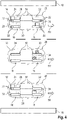
- FIG. 6 shows a schematic side view of a motor vehicle 10 with a vehicle control device 20 which is designed to guide motor vehicle 10 at least partially in an automated manner. At least partially autonomous driving is present intended.
- the vehicle control device 20 has a computer unit 16, the present -as from the Figures 1 to 5 as can be seen-comprises four computer nodes CN1 to CN4.
- the computer nodes CN1 to CN4 are in communication with one another via a communication bus.
- the communication bus is not indicated in the figures.
- the computer unit 16 has computer instances 22 that are used by applications 24 to 48, which are explained below, or are assigned to them.
- Motor vehicle 10 also includes surroundings sensors 68 which transmit corresponding surroundings signals to vehicle control device 20 , in particular computer unit 16 .
- vehicle control device 20 also makes motor vehicle operating data available that characterize operating states of motor vehicle 10 .
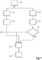
- the environment data and the motor vehicle operating data are given the reference number 52 ( 7 ) designated.
- a first application 54 and a redundant second application 56 are provided.
- the invention is not limited to the use of only two applications. Of course, several redundant second applications can also be provided.
- the first application 54 provides output data 56 and the redundant second application provides output data 60 .
- the output data 58, 60 are provided by the respective application 54, 56 depending on the motor vehicle operating data and/or environmental data 52.
- the output data 58, 60 serve, among other things, to contribute to the determination of vehicle guidance data 62, which allow the motor vehicle 10 to be guided at least partially in an automated manner.
- vehicle guidance data 62 can have a trajectory, for example, on which the driving of the motor vehicle 10 can be based.
- the motor vehicle 10 is in a communication connection ( Figures 2 to 5 ).
- the motor vehicle 10 receives the vehicle operating data 66 from the other vehicle 12.
- This vehicle operating data 66 is used for at least partially automated driving of the other vehicle 12 and can for driving the motor vehicle 10 can also be used.
- the corresponding computer instance 22 can even be fully released or deactivated, so that the computer capacity of the computer unit 16 can be made available for other functionalities.
- energy consumption in particular with regard to the computer unit 16, can of course also be reduced by deactivating the computer instance 22.
- the vehicle operating data 66 of the other vehicle 12 is supplied to a vehicle guidance data determination unit 64 for determining the vehicle guidance data.
- the vehicle operating data 66 are additionally supplied to a comparison unit 70, which is also supplied with the output data 60 .
- the comparison unit 70 compares the vehicle operating data 66 with the output data 60 to the extent that the vehicle operating data 66 are within a tolerance band that is predetermined as a result in relation to the output data 60 . If this is the case, the comparison unit 70 transmits the vehicle operating data 66 to the vehicle guidance data determination unit 64 instead of the output data 60 . At the same time, comparison unit 70 emits a corresponding control signal to vehicle control device 20 so that redundant second application 56 can switch to a standby state. The vehicle control device 20 then terminates the redundant second application 56 so that the computer instance 22 used by this redundant second application 56 can be deactivated provided there are no further obstacles to the change.
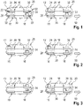
- 1 12 now shows an initial situation according to a first scenario, in which two at least partially autonomously guided motor vehicles 10, 12 are driving one behind the other in the same direction 50.
- Other vehicle 12 is the motor vehicle driving ahead, while motor vehicle 10 is the following motor vehicle.
- the structure of the vehicle control devices 20 of the motor vehicles 10, 12 is essentially the same in the present case, which is why it is only used for the Motor vehicle 10 is explained. In alternative configurations, the vehicle control devices 20 can also differ from one another.
- the first application 54 is usually operated in the active state. This active state is usually not ended in this scenario either.
- the motor vehicle 10 has the vehicle control device 20 with the computer unit 16, the computer unit 16 having four computer nodes CN1 to CN4 which are in communication with one another via a communication bus not further identified.
- Each computer node CN1 to CN4 has a number of computer instances 22 which can be activated or deactivated as required. However, they can also be activated variably with regard to the frequency of their use.
- Respective applications 24 to 34 are provided at the computer nodes CN1 to CN4, as shown in FIG 2 evident.
- the applications 24, 28, 32 are here trajectory planner applications, whereas the applications 26, 30, 34 are pedestrian detection applications. These applications are provided by way of example only to explain the operation of the invention. In alternative configurations, further or other applications can also be provided here.
- a solid line shows that the applications 24 and 34 are operated in the active state.
- the applications 26, 28, 30, 32 are shown with a dashed line, which means that although they are operated in an active state, their output signals or output data are not used to determine the vehicle guidance data.
- These applications serve as redundant second applications so that they can be used immediately when needed.
- the autonomous operation of motor vehicle 10 is therefore based primarily on applications 24 and 34, among other things.
- This vehicle operational data 66 may include, for example, relative acceleration, output data from a trajectory planner, and a pedestrian detection application.
- This data can from the motor vehicle 10 or the Vehicle control device 20 received and used to determine which redundant applications or instances for the intended autonomous driving operation of the motor vehicle 10 are not required, taking into account a predetermined safety level.
- the present embodiment shows that the applications 28 and 30 are no longer required for the required redundancy functionality.
- the applications 28, 30 compared to the first scenario 1 switch from the active state to the standby state and in this case even to a passive state in which they are completely deactivated.
- corresponding computer instances 22 are also released for the computer unit 16, so that the energy consumption can be reduced and/or computer resources can be released.
- the motor vehicle 10 can basically continue to be operated independently of the other vehicle 12 .
- the vehicle operating data 66 of the other vehicle 12 can also be used as redundancy for the redundant second applications that are in the standby state.
- the safety level that is specified can continue to be maintained. Should an active application of the motor vehicle 10 be disrupted, the operation of the motor vehicle 10 would be based on communication with the other vehicle 12 until a new application is activated. Likewise, if communications were disrupted, the motor vehicle 10 would only operate based on the active applications until new active instances are executed or communications are restored. In this case, only the output data of the redundant second application would be used again for determining the vehicle guidance data 62 .
- motor vehicle 10 drives behind other vehicle 12.
- the output data of trajectory planner application 24 of other vehicle 12 and of pedestrian detection application 34 can also be used by motor vehicle 10.
- the data transmission as such therefore allows the motor vehicle 10 to transfer the corresponding redundant second applications 28, 30 to the standby state. However, this is only carried out if the further requirements with regard to the safety level can be maintained.
- FIG. 3 shows a schematic representation of how 2 according to a third scenario, which is why for the following explanations in addition to the explanations 2 is referenced. In the following, only the differences will be presented.
- 3 shows the possibility of reducing an activation rate or frequency of use in an application that is a redundant second application.
- the corresponding application basically remains activated (degraded) so that it receives and processes input data for its intended operation and provides corresponding output data.
- fewer computer resources are made available to the computer unit 16 for processing the data.
- motor vehicle 10 compares vehicle operating data 66 received from other vehicle 12 with output data 58, 60 in order to determine whether safe driving of motor vehicle 10 can be guaranteed.
- the application operated in the standby mode is switched to the active state and the motor vehicle 10 is guided based on the output data 60 of this application.
- An important advantage of the reduced frequency standby state is that it still allows the motor vehicle 10 to be operated very quickly based on the output data 60 , for example if the pedestrian detection application 28 detects a pedestrian that was not recognized by the other vehicle 12 . If this application were only operated without using the output signals 60, the motor vehicle 10 could not use them to be able to detect the pedestrian.
- the continued operation of the redundant second application 56 with a lower frequency thus has an advantage in relation to the safe autonomous driving of the motor vehicle. This is in 3 for motor vehicle 10 with the field for application 34 with a gray background.
- the scenario according to 2 can occur, for example, in a city or urban setting.
- the motor vehicle 10 is required to have a higher level of safety, particularly with respect to the detection of pedestrians, because there is a high probability that there are many pedestrians in the vicinity.
- one pedestrian detection application remains as the active application 54 and another can operate in standby mode, specifically in a passive state.
- the scenario according to 3 can be assumed, for example, when operating on a freeway where significantly fewer pedestrians are to be expected. This is why it is possible here to select a standby state in which the frequency of use of the computer instance 22 is lower than in the active state.
- one of the trajectory planner applications is operated in the active state and one in a state in which the corresponding output data is not used (active-high). This is provided because the trajectory should be able to be calculated with the same frequency in both urban scenarios and freeway scenarios. Therefore, the trajectory planner application shall not be operated in a lower frequency mode.
- FIG. 1 shows a further embodiment according to a fourth scenario, in which a second third-party vehicle 14 is additionally provided. All three motor vehicles 10 to 14 are driving in the same direction 50 next to each other in respective adjacent lanes. The other vehicle 14 is driving in a left lane and overtakes the motor vehicle 10 which is driving in the middle lane. Other vehicle 12 is driving in a right lane. All three motor vehicles 10 to 14 are in communication with one another.
- the motor vehicle 10 can realize its autonomous operation with applications in the standby state, the respective applications being executed with a lower frequency than in the active state. This is possible because crossing pedestrians are extremely unlikely for the middle lane and other vehicles 12 and 14 can warn motor vehicle 10 in advance if they detect a pedestrian. However, the corresponding application is not completely shut down because a minimum of security requirements should be met.
- the motor vehicle 10 can determine its trajectory, in which case the trajectory planner application 32 can be executed here with a lower frequency than in the active state. This is possible because in this scenario motor vehicle 10, which is driving in the same direction between other vehicles 12 and 14, does not have much opportunity for trajectory changes and motor vehicle 10 knows, based on the communication, which positions for other vehicles 12 and 14 14 are to be expected. In addition, any objects that are detected in the direction of travel by other vehicles 12 and 14 can be transmitted to motor vehicle 10 .
- the road with the lanes on which the motor vehicles 10 to 14 drive are bordered by sidewalks 18 on the sides.
- FIG 5 shows a further embodiment of the invention using column operation.
- a guide vehicle is provided, which is motor vehicle 12 here.
- the motor vehicle 10 follows the leading vehicle 12 as the following vehicle. Even if only two motor vehicles are provided in the present case, the convoy formed as a result can of course have a plurality of motor vehicles following one another.
- the leading vehicle 12 transmits relevant vehicle operating data 66 to the following vehicle 10.
- the transmitted vehicle operating data 66 includes all necessary data for the autonomous following of the following vehicle 10
- the following vehicle 10 receives corresponding instructions from the leading vehicle 12 with regard to its operation.
- Appropriate applications are provided for this purpose, namely platoon manager applications 38, 40, 46, 48 and communication monitors 42, 44. These applications can be used to implement the platoon behavior.
- the platoon manager applications 38, 40, 46, 48 can be used to determine when a platoon can be formed. Additionally, the platoon manager applications 38, 40, 46, 48 may determine which of the automobiles 10, 12 should be the lead vehicle, for example.
- the communications monitor 42, 44 can continuously validate the reliability and quality of the communications link between the follower vehicle 10 and the leader vehicle 12. This application indicates when the follower vehicle 10 needs to be able to regain control. Such a takeover is necessary, for example, if the quality of the communication link decreases, the data is incomplete or invalid and/or the like.
- Every motor vehicle has a limited number of resources, in particular with regard to the computer unit 16.
- the invention enables computer instances 22 to be run and applications to be deactivated in such a way that computer resources can be saved and/or energy can be saved.
- safety can also be further improved in that vehicle operating data 66 of other vehicle 12 can be used to verify output data 58 , 60 of one's own motor vehicle 10 .
- the system reliability of the vehicle control device 20 can be improved because the motor vehicles 10, 12 can verify the output data 58, 60 by that of the respective other motor vehicle 10, 12.
Landscapes
- Engineering & Computer Science (AREA)
- Automation & Control Theory (AREA)
- Transportation (AREA)
- Mechanical Engineering (AREA)
- General Physics & Mathematics (AREA)
- Physics & Mathematics (AREA)
- Radar, Positioning & Navigation (AREA)
- Aviation & Aerospace Engineering (AREA)
- Remote Sensing (AREA)
- Human Computer Interaction (AREA)
- Theoretical Computer Science (AREA)
- Signal Processing (AREA)
- Computer Networks & Wireless Communication (AREA)
- Quality & Reliability (AREA)
- General Engineering & Computer Science (AREA)
- Safety Devices In Control Systems (AREA)
- Electric Propulsion And Braking For Vehicles (AREA)
- Control Of Position, Course, Altitude, Or Attitude Of Moving Bodies (AREA)
Abstract
Description
- Die Erfindung betrifft ein Verfahren zum teilweise automatisierten Führen eines Kraftfahrzeugs. Die Erfindung betrifft weiterhin ein Rechnerprogrammprodukt umfassend ein Programm für eine Rechnereinheit einer Fahrzeugsteuereinrichtung eines Kraftfahrzeugs. Ferner betrifft die Erfindung eine Fahrzeugsteuereinrichtung zum zumindest teilweise automatisierten Führen eines Kraftfahrzeugs. Schließlich betrifft die Erfindung auch ein Kraftfahrzeug mit einer Fahrzeugsteuerung zum zumindest teilweise automatisierten Führen des Kraftfahrzeugs.
- Gattungsgemäße Verfahren, gattungsgemäße Fahrzeugsteuereinrichtungen sowie gattungsgemäße Kraftfahrzeuge sind dem Grunde nach im Stand der Technik umfänglich bekannt, sodass es eines gesonderten druckschriftlichen Nachweises hierfür nicht bedarf. Automatisiert geführte Kraftfahrzeuge, insbesondere zumindest teilweise automatisiert geführte Kraftfahrzeuge, nutzen eine Mehrzahl von Rechnerprogrammanwendungen beziehungsweise Anwendungen, um Umgebungsinformationen zu analysieren. Die Umgebungsinformationen können in Form von Umgebungsdaten vorliegen, die mittels eines oder mehrerer Umgebungssensoren erfasst worden sind. Diese Anwendungen müssen zuverlässig und robust genug sein, um unter weitgehend beliebigen Umständen effektiv betrieben werden zu können. Rechnerprogrammanwendungen wie die, die in zumindest teilweise autonomen Kraftfahrzeugen ausgeführt werden, analysieren eine Vielzahl von Daten, um den besten Aktivitätskurs zu ermitteln. Darüber hinaus führen zumindest teilweise autonome Kraftfahrzeuge eine Mehrzahl von redundanten Rechnerinstanzen von wichtigen Anwendungen aus, um insgesamt ein robustes System erreichen zu können. Derartige Anwendungen sowie hierzu redundante Anwendungen benötigen jedoch eine signifikante Menge an Ressourcen, insbesondere in Bezug auf einen Verbrauch an Energie durch die jeweils ausgeführte Instanz und in Bezug auf Ressourcen von einer oder mehreren Rechnereinheiten.
- Die Erfindung befasst sich mit der Aufgabe, wenigstens den Verbrauch von Energie oder den Verbrauch von Ressourcen einer Rechnereinheit zu verbessern, insbesondere zu reduzieren.
- Als Lösung wird mit der Erfindung ein Verfahren, eine Fahrzeugsteuereinrichtung sowie ein Kraftfahrzeug gemäß den unabhängigen Ansprüchen vorgeschlagen.
- Vorteilhafte Weiterbildungen ergeben sich aus Merkmalen der abhängigen Ansprüche.
- In Bezug auf ein gattungsgemäßes Verfahren wird mit der Erfindung insbesondere vorgeschlagen, dass eine erste Anwendung und wenigstens eine redundante zweite Anwendung jeweils Ausgangsdaten abhängig von Kraftfahrzeugbetriebsdaten und/oder Umfelddaten bereitstellen, Fahrzeugführungsdaten zum zumindest teilweise automatisierten Führen des Kraftfahrzeugs abhängig von den Ausgangsdaten ermittelt werden, Fahrzeugbetriebsdaten eines Fremdfahrzeugs empfangen werden, und abhängig von den Fahrzeugbetriebsdaten des Fremdfahrzeugs die wenigstens eine redundante zweite Anwendung von einem Aktivzustand, in dem das Ermitteln der Fahrzeugführungsdaten unter Berücksichtigung der Ausgangsdaten der wenigstens einen redundanten zweiten Anwendung erfolgt, in einen Bereitschaftszustand wechselt, in dem eine von der wenigstens einen redundanten zweiten Anwendung genutzte Rechnerinstanz einer Rechnereinheit zumindest mit geringerer Häufigkeit als im Aktivzustand ausgeführt wird.
- In Bezug auf eine gattungsgemäße Steuereinrichtung wird mit der Erfindung insbesondere vorgeschlagen, dass die Fahrzeugsteuereinrichtung eine programmgesteuerte Rechnereinheit aufweist, die ausgebildet ist, mittels einer ersten Anwendung und wenigstens einer redundanten zweiten Anwendung jeweils Ausgangsdaten abhängig von Kraftfahrzeugbetriebsdaten und/oder Umfelddaten bereitzustellen, Fahrzeugführungsdaten zum zumindest teilweise automatisierten Führen des Kraftfahrzeugs abhängig von den Ausgangsdaten zu ermitteln, Fahrzeugbetriebsdaten eines Fremdfahrzeugs zu empfangen, und abhängig von den Fahrzeugbetriebsdaten des Fremdfahrzeugs die wenigstens eine redundante zweite Anwendung von einem Aktivzustand, in dem das Ermitteln der Fahrzeugführungsdaten unter Berücksichtigung der Ausgangsdaten der wenigstens einen redundanten zweiten Anwendung erfolgt, in einen Bereitschaftszustand zu wechseln, in dem eine von der wenigstens einen redundanten zweiten Anwendung genutzte Rechnerinstanz der Rechnereinheit zumindest mit geringerer Häufigkeit als im Aktivzustand ausgeführt wird.
- In Bezug auf ein gattungsgemäßes Kraftfahrzeug wird insbesondere vorgeschlagen, dass die Fahrzeugsteuereinrichtung gemäß der Erfindung ausgebildet ist.
- In Bezug auf ein Rechnerprogrammprodukt wird mit der Erfindung insbesondere vorgeschlagen, dass das Rechnerprogrammprodukt ein Programm für eine Rechnereinheit einer Fahrzeugsteuereinrichtung eines Kraftfahrzeugs umfasst, wobei das Programm Programmcodeabschnitte eines Programms zum Ausführen der Schritte des Verfahrens gemäß der Erfindung aufweist, wenn das Programm durch die Rechnereinheit ausgeführt wird.
- Die Erfindung basiert unter anderem auf dem Gedanken, eine dynamische Rekonfiguration einer Fahrzeugsteuereinrichtung basierend auf Informationen beziehungsweise Daten, erhalten von Fremdfahrzeugen, durchführen zu können. Die Fahrzeugsteuereinrichtung, insbesondere deren Rechnereinheit, analysiert einen aktuellen Kontext und bestimmt Anforderungen in Bezug auf einen Sicherheitspegel. Dadurch, dass beides genutzt werden kann, nämlich fahrzeugseitig selbst ermittelte Daten sowie Fahrzeugbetriebsdaten des Fremdfahrzeugs, kann die Fahrzeugsteuereinrichtung bestimmen, welche Systemkonfiguration, insbesondere in Bezug auf die wenigstens eine Rechnereinheit der Fahrzeugsteuereinrichtung, angepasst wird, wobei das Ziel ist, eine möglichst effiziente Konfiguration erreichen zu können. Dies umfasst unter anderem den Verbrauch von Energie sowie auch die Nutzung von Rechnerressourcen. Zugleich sollen die bestimmten Sicherheitsanforderungen beibehalten werden können. Dabei nutzt die Erfindung den weiteren Gedanken, solche Anwendungen zu identifizieren, die von einem Aktivzustand in einen Bereitschaftszustand wechseln können, beispielsweise weil der Pegel in Bezug auf Redundanz für diese Anwendung reduziert werden kann, oder die Häufigkeit der Ausführung dieser Anwendungen sowie insbesondere auch von damit verbundenen Rechnerinstanzen reduziert werden kann. Das Ausführen von weniger oder weniger ressourcenintensiven Anwendungen kann zum Reduzieren von Ressourcen, wie zuvor genannt, führen.
- Insbesondere für den Betrieb von zumindest teilweise automatisierten Fahrzeugen beziehungsweise zumindest teilweise autonomen Fahrzeugen sind eine Mehrzahl von Rechnerprogrammanwendungen erforderlich, zum Beispiel Wahrnehmung beziehungsweise Erfassen der Umgebung, Planung, insbesondere in Bezug auf das Ermitteln von Trajektorien, Fahrzeugkontrolldienste und/oder dergleichen. Im Allgemeinen ist eine Anwendung beziehungsweise eine Rechnerprogrammanwendung eine Funktion, die Eingangsdaten, beispielsweise Sensordaten, Daten von anderen Anwendungen oder dergleichen, in Ausgangsdaten umwandelt, beispielsweise Instruktionsdaten, Befehle, Analyse der Eingangsdaten und/oder dergleichen. Da viele solcher Rechnerprogrammanwendungen sicherheitskritisch sind, werden sie in redundanter Weise ausgeführt, das heißt, die Fahrzeugsteuereinrichtung führt mehrere Anwendungen aus, die die gleiche Funktionalität realisieren, zum Beispiel Ermitteln einer Trajektorie oder dergleichen. Die redundanten Anwendungen können entweder homogen sein, zum Beispiel indem eine spezifische Anwendung mehrmals zu einem Zeitpunkt ausgeführt wird, oder auch heterogen sein, indem mehrere unterschiedliche Anwendungen die gleiche Funktionalität bereitstellen.
- Die Erfindung nutzt ferner den Gedanken, dass das zumindest teilweise automatisiert geführte Kraftfahrzeug mit anderen Kraftfahrzeugen beziehungsweise Fremdfahrzeugen kommunizieren kann und Daten auf eine sichere, zuverlässige und schnelle Weise übermittelt werden können. Die erhaltenen Daten der Fremdfahrzeuge erlauben das Implementieren der Erfindung, indem die empfangenen Daten genutzt werden, zu bestimmen, ob eine Anwendung in einen Bereitschaftsmodus wechseln kann, zum Beispiel indem die Anzahl der ausgeführten Operationen reduziert werden kann, oder die Anwendung deaktiviert werden kann. Die Fahrzeugbetriebsdaten des Fremdfahrzeugs können zum Beispiel Daten von einem Lidar, einem Radar, einer Kamera, einem Tachometer, einem Temperatursensor, einem Bremssensor, einer Analyse von Sensordaten, Ausgangsdaten von Rechnerprogrammanwendungen, Daten eines GPS-Sensors und/oder dergleichen umfassen.
- Mit der Erfindung kann erreicht werden, dass der Wirkungsgrad erhöht und die Ressourcenzuordnung für Rechnerprogrammanwendungen optimiert werden können, vorzugsweise wenn bestimmte Bedingungen eingehalten werden. Zum Beispiel kann eine solche Bedingung sein, dass eine zuverlässige Kommunikation und ein zuverlässiger Datentransfer zwischen den Kraftfahrzeugen vorliegt. Sobald eine zuverlässige Kommunikation hergestellt ist, können die Kraftfahrzeuge untereinander Daten übermitteln, die von dem jeweils anderen Kraftfahrzeug genutzt werden können. Die empfangenen Daten können dazu genutzt werden, zu bestimmen, ob Rechnerprogrammanwendungen in den Bereitschaftszustand wechseln oder sogar deaktiviert werden können. Vorzugsweise ist dieser Wechsel von den Informationen, die übermittelt worden sind beziehungsweise empfangen worden sind, und von Kontextbedingungen abhängig, beispielsweise einem aktuellen Fahrzustand wie Fahrbahneigenschaften, Wetter, Verkehrssituation, der Zuverlässigkeit der Kommunikationsverbindung, einer Priorität der jeweiligen Rechnerprogrammanwendung und/oder dergleichen. Darüber hinaus kann der Wechsel auch von einem aktuellen Sicherheitspegel abhängig sein. Dabei kann vorgesehen sein, dass ein Wechsel in den Bereitschaftszustand nicht erlaubt wird, wenn dadurch der erreichte Sicherheitspegel unter einen vorgegebenen Sicherheitspegel fällt.
- Die erste Anwendung beziehungsweise Rechnerprogrammanwendung ist eine Anwendung, für die vorzugsweise ein kontinuierlicher bestimmungsgemäßer Betrieb vorgesehen ist. Die redundante zweite Anwendung ist dagegen eine Anwendung, die auf redundante Weise die gleiche Funktionalität bereitstellt und die zwischen dem Aktivzustand und dem Bereitschaftszustand wechseln kann. Findet keine Kommunikation zwischen dem Kraftfahrzeug und irgendeinem Fremdfahrzeug statt, ist die redundante zweite Anwendung in der Regel im Aktivzustand. In diesem Fall brauchen keine Fahrzeugbetriebsdaten eines Fremdfahrzeugs vorzuliegen. Werden dagegen Fahrzeugbetriebsdaten eines Fremdfahrzeugs empfangen, besteht die Möglichkeit, dass die redundante zweite Anwendung vom Aktivzustand in den Bereitschaftszustand wechseln kann, sodass die durch die redundante zweite Anwendung genutzte Rechnerinstanz der Rechnereinheit zumindest mit geringerer Häufigkeit als im Aktivzustand ausgeführt wird (englisch: degraded mode). Die von der redundanten zweiten Anwendung genutzte Rechnerinstanz kann zum Beispiel ein Maschinencode sein, der unmittelbar durch die Rechnereinheit ausgeführt wird.
- Im Aktivzustand stellt die redundante zweite Anwendung im Wesentlichen die gleiche Funktionalität wie die erste Anwendung bereit, sodass eine Redundanz erreicht werden kann. Im Bereitschaftszustand kann die Funktionalität eingeschränkt sein, oder sogar vollständig entfallen (englisch: active-low mode). Hierdurch kann nicht nur Energie eingespart werden, sondern dadurch, dass die Rechnerinstanz nicht mehr so häufig oder sogar gar nicht mehr benötigt wird, kann eine entsprechende Ressource der Rechnereinheit freigegeben werden, sodass andere Funktionen schneller und/oder besser ausgeführt werden können.
- Die Fahrzeugsteuereinheit weist vorzugsweise wenigstens eine Rechnereinheit auf, die es erlaubt, auf Basis eines Rechnerprogramms eine Funktionalität bereitzustellen.
- Gemäß einer Weiterbildung wird vorgeschlagen, dass die Fahrzeugführungsdaten vor dem Wechseln der wenigstens einen redundanten zweiten Anwendung vom Aktivzustand in den Bereitschaftszustand für einen vorgegebenen Zeitraum unabhängig von den Ausgangsdaten der wenigstens einen redundanten zweiten Anwendung ermittelt werden. In diesem Zustand liefert also die redundante zweite Anwendung weiterhin die volle Funktionalität, jedoch werden die entsprechenden Ausgangsdaten der redundanten zweiten Anwendung nicht weiter berücksichtigt (englisch: active-high mode). Dies erlaubt es, die Fahrzeugführungsdaten unter Nutzung der Fahrzeugbetriebsdaten des Fremdfahrzeugs zu ermitteln, wobei die Fahrzeugbetriebsdaten die redundante zweite Anwendung zumindest teilweise ersetzen können. Zugleich kann während dieses vorgegebenen Zeitraums sichergestellt werden, dass die zuverlässige Funktion zum Ermitteln der Fahrzeugführungsdaten weiterhin auch in Bezug auf die Redundanz gegeben ist. Sollte während des vorgegebenen Zeitraums eine Störung auftreten, kann unverzüglich auf die Nutzung der Ausgangsdaten der redundanten zweiten Anwendung umgeschaltet werden oder es können diese zusätzlich berücksichtigt werden, sodass das erforderliche Sicherheitsniveau beziehungsweise der gewünschte Sicherheitspegel weiterhin sichergestellt werden kann. Als besonders vorteilhaft erweist sich diese Ausgestaltung dann, wenn die Zuverlässigkeit der Kommunikation zwischen dem Kraftfahrzeug und dem Fremdfahrzeug sich verändert, insbesondere verschlechtert, oder nach dem Herstellen der Kommunikationsverbindung noch nicht die notwendige Zuverlässigkeit erreicht hat.
- Weiterhin wird vorgeschlagen, dass das Wechseln der wenigstens einen redundanten zweiten Anwendung vom Aktivzustand in den Bereitschaftszustand abhängig von einem Vergleich der Ausgangsdaten der wenigstens einen redundanten zweiten Anwendung mit den Fahrzeugbetriebsdaten des Fremdfahrzeugs erfolgt. Zu diesem Zweck können spezifische Daten der Fahrzeugbetriebsdaten des Fremdfahrzeugs ausgewählt werden, die dann mit den Ausgangsdaten der redundanten zweiten Anwendung verglichen werden können. Erst wenn durch den Vergleich ein hinreichendes Maß an Übereinstimmung erreicht worden ist, kann der Wechsel freigegeben werden oder ausgelöst werden. Darüber hinaus kann natürlich vorgesehen sein, dass das Vergleichen über einen vorgegebenen Zeitraum erfolgt und in diesem Zeitraum eine hinreichende Übereinstimmung im Wesentlichen kontinuierlich gegeben sein soll. Dadurch kann eine weitere Verbesserung der Verfahrensführung erreicht werden.
- Es wird ferner vorgeschlagen, dass der Bereitschaftszustand einen Passivzustand ohne Nutzung der Rechnerinstanz nutzt. Dies hat den Vorteil, dass die Rechnerinstanz freigegeben werden kann für die Nutzung durch andere Anwendungen oder sogar vollständig deaktiviert werden kann (englisch: active-low mode). Dadurch können Rechnerressourcen in Bezug auf die Rechnereinheit freigegeben werden. Schließlich kann dadurch auch die Rechnereinheit effizienter betrieben werden, weil die Anzahl der Rechenoperationen reduziert werden kann.
- Darüber hinaus wird vorgeschlagen, dass die Ausgangsdaten der ersten Anwendung mit den Fahrzeugbetriebsdaten des Fremdfahrzeugs verglichen werden. Diese Ausgestaltung ermöglicht es, einen Vergleich unabhängig von der redundanten zweiten Anwendung durchzuführen. Dadurch kann die Zuverlässigkeit weiter erhöht werden.
- Insbesondere wird vorgeschlagen, dass abhängig von diesem Vergleich die wenigstens eine redundante zweite Anwendung vom Bereitschaftszustand in den Aktivzustand wechselt. Diese Ausgestaltung ermöglicht es, während des Bereitschaftszustands der wenigstens einen redundanten zweiten Anwendung eine Überprüfung der Zuverlässigkeit durchzuführen und bei einem geringeren Sicherheitspegel als dem vorgegebenen Sicherheitspegel abhängig von dem Vergleich die wenigstens eine redundante zweite Anwendung wieder in den Aktivzustand zu überführen, sodass zum Beispiel die redundante zweite Anwendung die bestimmungsgemäße Funktionalität der ersten Anwendung parallel bereitstellt, sodass die Fahrzeugbetriebsdaten des Fremdfahrzeugs nicht mehr benötigt werden. Dies ist insbesondere dann von Vorteil, wenn sich aufgrund einer unzuverlässig werdenden Kommunikation zwischen dem Kraftfahrzeug und dem Fremdfahrzeug die empfangenen Fahrzeugbetriebsdaten des Fremdfahrzeugs nicht mehr hinreichend für eine zuverlässige Funktion der Fahrzeugsteuereinrichtung nutzen lassen, weil sie beispielsweise gestört oder unvollständig sind.
- Weiterhin wird vorgeschlagen, dass zum Wechseln zwischen dem Bereitschaftszustand und dem Aktivzustand der wenigstens einen redundanten zweiten Anwendung ein vorgegebener Sicherheitspegel berücksichtigt wird. Der Sicherheitspegel dient dazu, ein Maß für erforderliche Redundanz zur zuverlässigen automatisierten Führung des Kraftfahrzeugs vorzugeben. Der Sicherheitspegel kann situationsabhängig sein. Der Sicherheitspegel kann jeweils aktuell für eine bestimmte Fahrsituation beziehungsweise für einen bestimmten Fahrzustand ermittelt und mit dem vorgegebenen Sicherheitspegel verglichen werden. Ist der ermittelte Sicherheitspegel kleiner als der vorgegebene Sicherheitspegel, kann vorgesehen sein, dass die redundante zweite Anwendung permanent im Aktivzustand bleibt, das heißt, ein Wechsel in den Bereitschaftszustand verhindert wird.
- Es wird ferner vorgeschlagen, dass abhängig von einem Vergleich der Ausgangsdaten von wenigstens der ersten oder der wenigstens einen redundanten zweiten Anwendung mit den Fahrzeugbetriebsdaten des Fremdfahrzeugs ein Warnsignal abgegeben wird. Das Warnsignal kann vorzugsweise dann abgegeben werden, wenn der Vergleich ergibt, dass die Ausgangsdaten der jeweiligen Anwendung von den vorzugsweise relevanten Fahrzeugbetriebsdaten des Fremdfahrzeugs signifikant abweichen. Zu diesem Zweck kann ein Toleranzbereich vorgegeben werden, innerhalb dessen ein Warnsignal nicht abgegeben zu werden braucht. Das Warnsignal wird vorzugsweise dann abgegeben, wenn durch die Fahrzeugbetriebsdaten des Fremdfahrzeugs der Toleranzbereich, der vorzugsweise durch die Ausgangsdaten vorgegeben sein kann, verlassen wird. Das Warnsignal kann dazu dienen, eine Meldung an einen Fahrzeuginsassen des Kraftfahrzeugs, insbesondere den Fahrer des Kraftfahrzeugs, abzugeben. Es kann aber lediglich ein Warnsignal für die Fahrzeugsteuereinrichtung abgegeben werden.
- Gemäß einer Weiterbildung wird vorgeschlagen, dass ein aktueller Fahrzustand des Kraftfahrzeugs ermittelt wird und die wenigstens eine redundante zweite Anwendung ergänzend abhängig vom aktuellen Fahrzustand im Aktivzustand oder dem Bereitschaftszustand betrieben wird. Diese Weiterbildung erlaubt es zu berücksichtigen, dass bei bestimmten Fahrsituationen, die durch einen aktuell durch den aktuellen Fahrzustand des Kraftfahrzeugs bestimmt sein können, das Einnehmen des Bereitschaftszustands durch die wenigstens eine redundante zweite Anwendung möglichst vermieden werden soll. Dies kann zum Beispiel dann vorteilhaft sein, wenn das Kraftfahrzeug in einem Bereich betrieben wird, bei dem sehr viele Fußgänger, beispielsweise Kinder oder dergleichen, im Umfeld vorhanden sind. Dies kann eine besonders hohe Zuverlässigkeit beziehungsweise einen besonders hohen Sicherheitspegel erfordern, wobei berücksichtigt werden kann, dass das Fremdfahrzeug möglicherweise nicht alle relevanten Umfelddaten zur Verfügung stellen vermag.
- Darüber hinaus wird vorgeschlagen, dass eine Zuverlässigkeit einer Kommunikationsverbindung zum Fremdfahrzeug ermittelt wird und die wenigstens eine redundante zweite Anwendung ergänzend abhängig von der Zuverlässigkeit im Aktivzustand oder im Bereitschaftszustand betrieben wird. Diese Ausgestaltung erlaubt es, abhängig von der Zuverlässigkeit der Kommunikationsverbindung die redundante zweite Anwendung im Aktivzustand zu halten oder es zu erlauben, den Bereitschaftszustand einzunehmen. Ist die Kommunikationsverbindung beispielsweise unzuverlässig, das heißt, dass die Fahrzeugbetriebsdaten des Fremdfahrzeugs nur zeitweise oder auch nur unvollständig übermittelt werden, wird der Aktivzustand beibehalten. Erst wenn die Zuverlässigkeit ein vorgegebenes Maß erreicht, kann das Einnehmen des Bereitschaftszustands freigegeben werden.
- Ferner wird vorgeschlagen, dass die wenigstens eine redundante zweite Anwendung ergänzend abhängig von einer Priorität in Bezug auf die erste und die wenigstens eine redundante zweite Anwendung im Aktivzustand oder dem Bereitschaftszustand betrieben wird. Die Priorität kann zum Beispiels anwendungsbezogen sein. Beispielsweise kann sich die Priorität darauf beziehen, dass eine Anwendung Fußgänger erkennt. Eine derartige Anwendung wird in der Regel eine große Priorität aufweisen. Eine andere Anwendung kann sich zum Beispiel darauf beziehen, Wetterbedingungen zu ermitteln. Eine derartige Anwendung kann zum Beispiel eine entsprechend kleinere Priorität aufweisen. Die Priorität braucht im bestimmungsgemäßen Betrieb der Fahrzeugsteuereinrichtung nicht konstant zu sein und kann situationsabhängig variiert werden. Dem Grunde nach kann die Priorität jedoch auch fest vorgegeben sein.
- Es wird ferner vorgeschlagen, dass die wenigstens eine redundante zweite Anwendung ergänzend abhängig von einem Kolonnenbetrieb im Bereitschaftszustand betrieben wird. Bei dieser Weiterbildung kann vorgesehen sein, dass die Fahrzeugsteuereinrichtung einen Kolonnenbetrieb zu erkennen vermag und mit einem oder mehreren Fremdfahrzeugen einen entsprechenden Betriebsmodus einnimmt. Eines der Kraftfahrzeuge wird dann ein Führungsfahrzeug sein, wohingegen die anderen Fahrzeuge Folgefahrzeuge sind. Bei einem solchen Kolonnenbetrieb können eine Reihe von für den zumindest teilweise autonomen Betrieb des Kraftfahrzeugs als Folgefahrzeug erforderlichen Fahrzeugführungsdaten vom Führungsfahrzeug bereitgestellt werden, sodass jeweilige redundante zweite Anwendungen für eine Reihe von Funktionalitäten nicht erforderlich zu sein brauchen. Daher kann bei einem solchen Betriebszustand die jeweilige redundante zweite Anwendung überwiegend beziehungsweise dauerhaft im Bereitschaftszustand sein. Lediglich wenn der Kolonnenbetrieb beendet wird, braucht dann die wenigstens eine redundante zweite Anwendung aktiviert zu werden, indem sie vom Bereitschaftszustand in den Aktivzustand wechselt.
- Die für das erfindungsgemäße Verfahren angegebenen Vorteile und Wirkungen gelten gleichermaßen auch für das Rechnerprogrammprodukt der Erfindung, die Fahrzeugsteuereinrichtung der Erfindung sowie das Kraftfahrzeug gemäß der Erfindung und umgekehrt. Insbesondere können daher Verfahrensmerkmale auch vorrichtungstechnisch und umgekehrt formuliert sein.
- Zu der Erfindung gehören auch Weiterbildungen der erfindungsgemäßen Fahrzeugsteuereinrichtung und des erfindungsgemäßen Kraftfahrzeugs, die Merkmale aufweisen, wie sie bereits im Zusammenhang mit den Weiterbildungen des erfindungsgemäßen Verfahrens beschrieben worden sind. Aus diesem Grund sind die entsprechenden Weiterbildungen der erfindungsgemäßen Fahrzeugsteuereinrichtung und des erfindungsgemäßen Kraftfahrzeugs hier nicht noch einmal beschrieben.
- Die Erfindung umfasst auch die Kombinationen der Merkmale der beschriebenen Ausführungsformen.
- Im Folgenden werden Ausführungsbeispiele der Erfindung beschrieben. Hierzu zeigt:
- Fig. 1
- in einer schematischen Draufsicht zwei hintereinander in die gleiche Richtung fahrende Kraftfahrzeuge, die vorliegend gemäß einem ersten Szenario unabhängig voneinander autonom geführt sind;
- Fig. 2
- eine schematische Darstellung wie
Fig. 1 , wobei die Kraftfahrzeuge gemäß einem zweiten Szenario über Car-to-Car-Kommunikation miteinander in Kommunikationsverbindung stehen und Fahrzeugbetriebsdaten austauschen, wobei das folgende Kraftfahrzeug redundante Anwendungen in einem Bereitschaftszustand betreibt; - Fig. 3
- eine schematische Darstellung wie
Fig. 2 , bei der eine redundante zweite Anwendung gemäß einem dritten Szenario in einem Passivbetriebszustand betrieben wird, bei dem die zuständige Rechnerinstanz deaktiviert ist; - Fig. 4
- eine schematische Darstellung wie
Fig. 3 mit drei nebeneinander in die gleiche Richtung auf einer Straße fahrenden Kraftfahrzeugen gemäß einem vierten Szenario, wobei in Bezug auf das mittlere Fahrzeug zwei redundante zweite Anwendungen in einem Passivbetriebszustand betrieben werden; - Fig. 5
- eine schematische Darstellung wie
Fig. 1 für einen Kolonnenbetrieb gemäß einem fünften Szenario; - Fig. 6
- eine schematische Seitenansicht eines Kraftfahrzeugs gemäß der Erfindung; und
- Fig. 7
- ein schematisches Ablaufdiagramm für eine Verfahrensführung gemäß der Erfindung.
- Bei den im Folgenden erläuterten Ausführungsbeispielen handelt es sich um bevorzugte Ausführungsbeispiele der Erfindung. Bei den Ausführungsbeispielen stellen die beschriebenen Komponenten jeweils einzelne, unabhängig voneinander zu betrachtende Merkmale der Erfindung dar, welche die Erfindung jeweils auch unabhängig voneinander weiterbilden und damit auch einzeln oder in einer anderen als der gezeigten Kombination als Bestandteil der Erfindung anzusehen sind. Des Weiteren sind die beschriebenen Ausführungsbeispiele auch durch weitere der bereits beschriebenen Merkmale der Erfindung ergänzbar.
- In den Figuren sind funktionsgleiche Elemente jeweils mit denselben Bezugszeichen versehen.
-
Fig. 6 zeigt in einer schematischen Seitenansicht ein Kraftfahrzeug 10 mit einer Fahrzeugsteuereinrichtung 20, die ausgebildet ist, das Kraftfahrzeug 10 zumindest teilweise automatisiert zu führen. Vorliegend ist ein zumindest teilweise autonomer Fahrbetrieb vorgesehen. Die Fahrzeugsteuereinrichtung 20 weist eine Rechnereinheit 16 auf, die vorliegend -wie aus denFig. 1 bis 5 ersichtlich ist-vier Rechnerknoten CN1 bis CN4 umfasst. Die Rechnerknoten CN1 bis CN4 stehen über einen Kommunikationsbus miteinander in Kommunikationsverbindung. In den Figuren ist der Kommunikationsbus nicht bezeichnet. AusFig. 6 ist ferner ersichtlich, dass die Rechnereinheit 16 Rechnerinstanzen 22 aufweist, die von Anwendungen 24 bis 48, die im Folgenden noch erläutert werden, genutzt werden beziehungsweise diesen zugeordnet sind. - Das Kraftfahrzeug 10 umfasst ferner Umfeldsensoren 68, die entsprechende Umfeldsignale an die Fahrzeugsteuereinrichtung 20, insbesondere die Rechnereinheit 16, übermitteln. Darüber hinaus stellt die Fahrzeugsteuereinrichtung 20 auch Kraftfahrzeugbetriebsdaten zur Verfügung, die Betriebszustände des Kraftfahrzeugs 10 kennzeichnen. Die Umfelddaten und die Kraftfahrzeugsbetriebsdaten sind vorliegend mit dem Bezugszeichen 52 (
Fig. 7 ) bezeichnet. -
Fig. 7 zeigt in einem schematischen Ablaufdiagramm einen möglichen verfahrensmäßigen Ablauf gemäß der Erfindung. In alternativen Ausgestaltungen können natürlich auch noch ergänzende und/oder alternative Schritte, beispielsweise gemäß Merkmalen von abhängigen Ansprüchen vorgesehen sein. - Gemäß
Fig. 7 sind eine erste Anwendung 54 und eine redundante zweite Anwendung 56 vorgesehen. Die Erfindung ist jedoch nicht auf die Nutzung von lediglich zwei Anwendungen beschränkt. Natürlich können auch mehrere redundante zweite Anwendungen vorgesehen sein. Die erste Anwendung 54 stellt Ausgangsdaten 56 und die redundante zweite Anwendung Ausgangsdaten 60 bereit. Die Ausgangsdaten 58, 60 werden durch die jeweilige Anwendung 54, 56 abhängig von den Kraftfahrzeugsbetriebsdaten und/oder Umfelddaten 52 bereitgestellt. - Die Ausgangsdaten 58, 60 dienen unter anderem dazu, zum Ermitteln von Fahrzeugführungsdaten 62 beizutragen, die es erlauben, das Kraftfahrzeug 10 zumindest teilweise automatisiert zu führen. Die Fahrzeugführungsdaten 62 können zum Beispiel eine Trajektorie aufweisen, die dem Führen des Kraftfahrzeugs 10 zugrundegelegt werden kann.
- Wie anhand der
Fig. 1 bis 5 im Folgenden noch erläutert werden wird, steht das Kraftfahrzeug 10 über Car-to-Car-Kommunikation mit einem Fremdfahrzeug 12, welches ebenfalls ein Kraftfahrzeug ist, in Kommunikationsverbindung (Fig. 2 bis 5 ). Das Kraftfahrzeug 10 empfängt vom Fremdfahrzeug 12 dessen Fahrzeugbetriebsdaten 66. Diese Fahrzeugbetriebsdaten 66 dienen dem zumindest teilweise automatisierten Führen des Fremdfahrzeugs 12 und können für das Führen des Kraftfahrzeugs 10 ergänzend genutzt werden. Insbesondere ist es möglich, die Funktion der Fahrzeugsteuereinrichtung 20 zu überwachen und unter Umständen auch zu vereinfachen, indem nämlich die redundante zweite Anwendung 56 von einem Aktivzustand, in dem das Ermitteln der Fahrzeugführungsdaten 62 unter Berücksichtigung der Ausgangsdaten 60 der redundanten zweiten Anwendung 56 erfolgt, in einen Bereitschaftszustand wechselt, in dem eine von der redundanten zweiten Anwendung 56 genutzte Rechnerinstanz 22 der Rechnereinheit 16 zumindest mit geringerer Häufigkeit als im Aktivzustand ausgeführt wird. Besonders vorteilhaft kann die entsprechende Rechnerinstanz 22 sogar vollständig freigegeben beziehungsweise deaktiviert werden, sodass Rechnerkapazität der Rechnereinheit 16 für andere Funktionalitäten zur Verfügung gestellt werden kann. Darüber hinaus kann natürlich auch durch das Deaktivieren der Rechnerinstanz 22 ein Energieverbrauch, insbesondere in Bezug auf die Rechnereinheit 16, reduziert werden. - Zu diesem Zweck ist vorliegend vorgesehen, dass die Fahrzeugbetriebsdaten 66 des Fremdfahrzeugs 12 einer Fahrzeugführungsdatenermittlungseinheit 64 zum Ermitteln der Fahrzeugführungsdaten zugeführt werden. Darüber hinaus werden die Fahrzeugbetriebsdaten 66 ergänzend einer Vergleichseinheit 70 zugeführt, der ebenfalls die Ausgangsdaten 60 zugeführt werden.
- Die Vergleichseinheit 70 vergleicht die Fahrzeugbetriebsdaten 66 mit den Ausgangsdaten 60 dahingehend, dass die Fahrzeugbetriebsdaten 66 in Bezug auf die Ausgangsdaten 60 in einem hierdurch vorgegebenen Toleranzband sind. Ist dies der Fall, werden von der Vergleichseinheit 70 anstelle der Ausgangsdaten 60 die Fahrzeugbetriebsdaten 66 an die Fahrzeugführungsdatenermittlungseinheit 64 übermittelt. Zugleich gibt die Vergleichseinheit 70 ein entsprechendes Steuersignal an die Fahrzeugsteuereinrichtung 20 ab, dass die redundante zweite Anwendung 56 in einen Bereitschaftszustand wechseln kann. Die Fahrzeugsteuereinrichtung 20 beendet dann die redundante zweite Anwendung 56, sodass die durch diese redundante zweite Anwendung 56 genutzte Rechnerinstanz 22 deaktiviert werden kann, sofern keine weiteren Wechselhindernisse vorliegen.
-
Fig. 1 zeigt nun eine Ausgangssituation gemäß einem ersten Szenario, bei der zwei zumindest teilweise autonom geführte Kraftfahrzeuge 10, 12 hintereinander in die gleiche Richtung 50 fahren. Das Fremdfahrzeug 12 ist das vorausfahrende Kraftfahrzeug, während das Kraftfahrzeug 10 das folgende Kraftfahrzeug ist. Der Aufbau der Fahrzeugsteuereinrichtungen 20 der Kraftfahrzeuge 10, 12 ist vorliegend im Wesentlichen gleich, weshalb er lediglich für das Kraftfahrzeug 10 erläutert wird. Bei alternativen Ausgestaltungen können die Fahrzeugsteuereinrichtungen 20 auch voneinander abweichen. - Die erste Anwendung 54 ist in der Regel im Aktivzustand betrieben. Dieser Aktivzustand wird bei diesem Szenario üblicherweise auch nicht beendet.
- Zu erkennen ist, dass das Kraftfahrzeug 10 die Fahrzeugsteuereinrichtung 20 mit der Rechnereinheit 16 aufweist, wobei die Rechnereinheit 16 vier Rechnerknoten CN1 bis CN4 aufweist, die untereinander über einen nicht weiter bezeichneten Kommunikationsbus miteinander in Kommunikationsverbindung stehen. Jeder Rechnerknoten CN1 bis CN4 weist mehrere Rechnerinstanzen 22 auf, die je nach Bedarf aktiviert beziehungsweise deaktiviert werden können. Sie können jedoch auch hinsichtlich der Häufigkeit ihrer Nutzung variabel aktiviert werden.
- An den Rechnerknoten CN1 bis CN4 sind jeweilige Anwendungen 24 bis 34 vorgesehen, wie aus
Fig. 2 ersichtlich. Die Anwendungen 24, 28, 32 sind vorliegend Trajektorienplaneranwendungen, wohingegen die Anwendungen 26, 30, 34 Fußgängerdetektionsanwendungen sind. Diese Anwendungen sind lediglich beispielhaft vorgesehen, um die Funktion der Erfindung zu erläutern. Bei alternativen Ausgestaltungen können hier auch weitere oder andere Anwendungen vorgesehen sein. - Mit einer durchgezogenen Linie ist dargestellt, dass die Anwendungen 24 und 34 im Aktivzustand betrieben sind. Dagegen sind die Anwendungen 26, 28, 30, 32 mit einer gestrichelten Linie dargestellt, was bedeutet, dass sie zwar in einem Aktivzustand betrieben werden, jedoch deren Ausgangssignale beziehungsweise Ausgangsdaten zum Ermitteln der Fahrzeugführungsdaten nicht herangezogen werden. Diese Anwendungen dienen als redundante zweite Anwendungen, um im Bedarfsfall unverzüglich genutzt werden zu können. Der autonome Betrieb des Kraftfahrzeugs 10 basiert daher vorliegend unter anderem überwiegend auf den Anwendungen 24 und 34.
-
Fig. 2 zeigt nun eine vergleichbare Situation wie inFig. 1 in einer schematischen Darstellung gemäß einem zweiten Szenario, wobei das Kraftfahrzeug 10 mit dem Fremdfahrzeug 12 in Kommunikationsverbindung steht und vom Fremdfahrzeug 12 Fahrzeugbetriebsdaten 66 empfängt. Diese Fahrzeugbetriebsdaten 66 können zum Beispiel eine relative Beschleunigung, Ausgangsdaten eines Trajektorienplaners und einer Fußgängerdetektionsanwendung umfassen. Diese Daten können vom Kraftfahrzeug 10 beziehungsweise der Fahrzeugsteuereinrichtung 20 empfangen und genutzt werden, um zu ermitteln, welche redundanten Anwendungen beziehungsweise Instanzen für den bestimmungsgemäßen autonomen Fahrbetrieb des Kraftfahrzeugs 10 unter Beachtung eines vorgegebenen Sicherheitspegels nicht erforderlich sind. In der vorliegenden Ausgestaltung zeigt sich, dass die Anwendungen 28 und 30 für die erforderliche Redundanzfunktionalität nicht mehr erforderlich sind. Daher ist vorliegend vorgesehen, dass abhängig von den Fahrzeugbetriebsdaten 66 die Anwendungen 28, 30 gegenüber dem ersten Szenario gemäßFig. 1 vom Aktivzustand in den Bereitschaftszustand wechseln und vorliegend sogar in einen Passivzustand, bei dem sie vollständig deaktiviert sind. Dadurch werden auch entsprechende Rechnerinstanzen 22 für die Rechnereinheit 16 freigegeben, sodass der Energieverbrauch reduziert und/oder Rechnerressourcen freigegeben werden können. - In dem Szenario gemäß
Fig. 2 ist lediglich vorgesehen, dass die redundanten zweiten Anwendungen in den Bereitschaftszustand wechseln. Die aktiven ersten Anwendungen 24, 34 bleiben weiter voll im Aktivzustand. Daher kann das Kraftfahrzeug 10 dem Grunde nach weiterhin unabhängig vom Fremdfahrzeug 12 betrieben werden. Jedoch können die Fahrzeugbetriebsdaten 66 des Fremdfahrzeugs 12 auch als Redundanz für die redundanten zweiten Anwendungen genutzt werden, die im Bereitschaftszustand sind. Dadurch kann der Sicherheitspegel, der vorgegeben ist, weiterhin eingehalten werden. Sollte eine aktive Anwendung des Kraftfahrzeugs 10 gestört sein, würde der Betrieb des Kraftfahrzeugs 10 auf der Kommunikation mit dem Fremdfahrzeug 12 basieren, bis eine neue Anwendung aktiviert ist. Gleichermaßen würde, wenn die Kommunikation gestört wäre, das Kraftfahrzeug 10 nur auf Basis der aktiven Anwendungen betrieben werden, bis neue aktive Instanzen ausgeführt werden oder die Kommunikation wiederhergestellt ist. In diesem Fall würden lediglich die Ausgangsdaten der redundanten zweiten Anwendung wieder für das Ermitteln der Fahrzeugführungsdaten 62 herangezogen. - Bei dem in
Fig. 2 dargestellten zweiten Szenario fährt das Kraftfahrzeug 10 hinter dem Fremdfahrzeug 12. In diesem Fall können die Ausgangsdaten der Trajektorienplaneranwendung 24 des Fremdfahrzeugs 12 und der Fußgängerdetektionsanwendung 34 vom Kraftfahrzeug 10 ebenfalls genutzt werden. Die Datenübertragung als solche erlaubt es dem Kraftfahrzeug 10 daher, die entsprechenden redundanten zweiten Anwendungen 28, 30 in den Bereitschaftszustand zu überführen. Dies wird jedoch nur dann ausgeführt, wenn die weiteren Anforderungen bezüglich des Sicherheitspegels gehalten werden können. -
Fig. 3 zeigt eine schematische Darstellung wieFig. 2 gemäß einem dritten Szenario, weshalb für die folgenden Erläuterungen ergänzend auf die Ausführungen zuFig. 2 verwiesen wird. Im Folgenden sollen lediglich die Unterschiede dargestellt werden. -
Fig. 3 zeigt die Möglichkeit, bei einer Anwendung, die eine redundante zweite Anwendung ist, eine Aktivierungsrate beziehungsweise Häufigkeit der Nutzung zu reduzieren. Das bedeutet, dass die entsprechende Anwendung weniger häufig ausgeführt wird. Jedoch bleibt die entsprechende Anwendung dem Grunde nach weiterhin aktiviert (degraded), sodass sie Eingangsdaten für ihren bestimmungsgemäßen Betrieb empfängt, verarbeitet und entsprechende Ausgangsdaten bereitstellt. Jedoch werden für die Verarbeitung der Daten weniger Rechnerressourcen der Rechnereinheit 16 zur Verfügung gestellt. InFig. 3 vergleicht zum Beispiel das Kraftfahrzeug 10 die vom Fremdfahrzeug 12 erhaltenen Fahrzeugbetriebsdaten 66 mit den Ausgangsdaten 58, 60, um zu bestimmen, ob ein sicheres Führen des Kraftfahrzeugs 10 gewährleistet werden kann. Im anderen Fall wird die im Bereitschaftsmodus betriebene Anwendung in den Aktivzustand überführt und das Kraftfahrzeug 10 basierend auf den Ausgangsdaten 60 dieser Anwendung geführt. - Ein wichtiger Vorteil des Bereitschaftszustands mit geringerer Häufigkeit ist, dass es dem Kraftfahrzeug 10 weiterhin möglich ist, sehr schnell auf Basis der Ausgangsdaten 60 betrieben werden zu können, zum Beispiel wenn die Fußgängerdetektionsanwendung 28 einen Fußgänger detektiert, der vom Fremdfahrzeug 12 nicht erkannt wurde. Würde nämlich diese Anwendung nur ohne Nutzung der Ausgangssignale 60 betrieben, könnte das Kraftfahrzeug 10 diese nicht nutzen, um den Fußgänger detektieren zu können. Der Weiterbetrieb der redundanten zweiten Anwendung 56 mit einer geringeren Häufigkeit hat hier also einen Vorteil in Bezug auf das sichere autonome Führen des Kraftfahrzeugs. Dies ist in
Fig. 3 für das Kraftfahrzeug 10 mit dem grau unterlegten Feld für die Anwendung 34 dargestellt. - Auch wenn die Ausgestaltungen gemäß
Fig. 3 und Fig. 2 ähnlich erscheinen, sind sie doch unterschiedlich. Das Szenario gemäßFig. 2 kann zum Beispiel in einer Stadt oder einem urbanen Umfeld auftreten. In diesem Fall ist für das Kraftfahrzeug 10 ein höherer Sicherheitspegel, insbesondere in Bezug auf die Erkennung von Fußgängern, gefordert, weil eine Wahrscheinlichkeit, dass viele Fußgänger in der Umgebung vorhanden sind, groß ist. Für diesen Fall verbleibt eine Fußgängerdetektionsanwendung als aktive Anwendung 54 und eine andere kann im Bereitschaftsmodus betrieben werden, insbesondere in einem Passivzustand. Das Szenario gemäßFig. 3 kann zum Beispiel bei einem Betrieb auf einer Autobahn angenommen werden, wo erheblich weniger Fußgänger zu erwarten sind. Aus diesem Grund ist es hier möglich, einen Bereitschaftszustand zu wählen, bei dem die Häufigkeit der Nutzung der Rechnerinstanz 22 geringer als im Aktivzustand ist. - In diesem Zusammenhang wird ferner darauf hingewiesen, dass im Ausführungsbeispiel gemäß
Fig. 2 eine der Trajektorienplaneranwendungen im Aktivzustand und eine in einem Zustand betrieben wird, bei der die entsprechenden Ausgangsdaten nicht genutzt werden (active-high). Dies ist deshalb vorgesehen, weil sowohl bei urbanen Szenarien als auch bei Autobahnszenarien die Trajektorie mit derselben Häufigkeit beziehungsweise Frequenz berechnet werden können soll. Daher soll die Trajektorienplaneranwendung nicht in einem Modus mit geringerer Häufigkeit betrieben werden. -
Fig. 4 zeigt eine weitere Ausgestaltung gemäß einem vierten Szenario, bei dem zusätzlich ein zweites Fremdfahrzeug 14 vorgesehen ist. Alle drei Kraftfahrzeuge 10 bis 14 fahren in die gleich Richtung 50 nebeneinander auf jeweiligen benachbarten Fahrspuren. Das Fremdfahrzeug 14 fährt auf einer linken Fahrspur und überholt das Kraftfahrzeug 10, welches auf der mittleren Fahrspur fährt. Das Fremdfahrzeug 12 fährt auf einer rechten Fahrspur. Alle drei Kraftfahrzeuge 10 bis 14 stehen in Kommunikationsverbindung miteinander. - Das Kraftfahrzeug 10 kann wegen dieser Kommunikation seinen autonomen Betrieb mit Anwendungen im Bereitschaftszustand realisieren, wobei die jeweiligen Anwendungen mit geringerer Häufigkeit als im Aktivzustand ausgeführt werden. Dies ist deshalb möglich, weil kreuzende Fußgänger für die mittlere Fahrbahn außerordentlich unwahrscheinlich sind und die Fremdfahrzeuge 12 und 14 das Kraftfahrzeug 10 vorwarnen können, wenn sie einen Fußgänger detektieren. Jedoch ist die entsprechende Anwendung nicht vollständig heruntergefahren, weil ein Minimum an Sicherheitsanforderung erfüllt sein soll.
- Gleichermaßen kann das Kraftfahrzeug 10 seine Trajektorie ermitteln, wobei die Trajektorienplaneranwendung 32 hier mit geringerer Häufigkeit als im Aktivzustand ausgeführt werden kann. Dies ist deshalb möglich, weil für das Kraftfahrzeug 10 in diesem Szenario, welches zwischen den Fremdfahrzeugen 12 und 14 in die gleiche Richtung fährt, keine großen Möglichkeiten für Trajektorienänderungen vorhanden sind und das Kraftfahrzeug 10 aufgrund der Kommunikation weiß, welche Positionen für die Fremdfahrzeuge 12 und 14 zu erwarten sind. Darüber hinaus können jegliche Objekte, die in Fahrtrichtung durch die Fremdfahrzeuge 12 und 14 erkannt werden, an das Kraftfahrzeug 10 übermittelt werden.
- Die Straße mit den Fahrbahnen, auf denen die Kraftfahrzeuge 10 bis 14 fahren, sind seitlich von Bürgersteigen 18 eingefasst.
- Basierend auf
Fig. 1 kann im Folgenden ein weiteres Szenario möglich sein. Bei diesem Szenario wird angenommen, dass kein Passivzustand für irgendeine der Anwendungen 24 bis 34 auftritt. Beide Fahrzeuge 10, 12 kommunizieren miteinander und übermitteln gegenseitig relevante Daten. Obwohl beide Fahrzeuge 10, 12 ihre jeweiligen Rechnereinheiten 16 rekonfigurieren könnten, um Ressourcen zu sparen, ist ein entsprechender Passivbetriebszustand nicht vorgesehen. Die Kommunikation zwischen den Kraftfahrzeugen 10 und 12 dient daher als Validierungsquelle, das heißt, dass ein jeweiliges der Kraftfahrzeuge 10, 12 die empfangenen Fahrzeugbetriebsdaten 66 dazu nutzt, die Ausgangsdaten 58, 60 der jeweiligen Anwendungen 54, 56 zu validieren. -
Fig. 5 zeigt eine weitere Ausgestaltung der Erfindung unter Nutzung eines Kolonnenbetriebs. Bei dieser Ausgestaltung ist ein Führungsfahrzeug vorgesehen, welches hier das Kraftfahrzeug 12 ist. Dem Führungsfahrzeug 12 folgt das Kraftfahrzeug 10 als Folgefahrzeug. Auch wenn nur zweit Kraftfahrzeuge vorliegend vorgesehen sind, kann die hierdurch gebildete Kolonne natürlich eine Mehrzahl von aufeinander folgenden Kraftfahrzeugen aufweisen. - Das Führungsfahrzeug 12 übermittelt relevante Fahrzeugbetriebsdaten 66 zum Folgefahrzeug 10. In diesem Fall, bei dem die übermitteln Fahrzeugbetriebsdaten 66 alle erforderlichen Daten für das autonome Folgen des Folgefahrzeugs 10 umfassen, erhält das Folgefahrzeug 10 entsprechende Anweisungen vom Führungsfahrzeug 12 bezüglich dessen Betriebs. Hierfür sind entsprechende Anwendungen vorgesehen, nämlich Kolonnenmanageranwendungen 38, 40, 46, 48 sowie Kommunikationsüberwachungen 42, 44. Diese Anwendungen können dazu genutzt werden, das Kolonnenverhalten zu realisieren.
- Die Kolonnenmanageranwendungen 38, 40, 46, 48 können dazu genutzt werden, zu ermitteln, wann eine Kolonne gebildet werden kann. Darüber hinaus können die Kolonnenmanageranwendungen 38, 40, 46, 48 zum Beispiel bestimmen, welches der Kraftfahrzeuge 10, 12 das Führungsfahrzeug sein soll. Die Kommunikationsüberwachung 42, 44 kann kontinuierlich die Zuverlässigkeit und Qualität der Kommunikationsverbindung des Folgefahrzeugs 10 mit dem Führungsfahrzeug 12 validieren. Diese Anwendung zeigt an, wann das Folgefahrzeug 10 die eigene Kontrolle wieder übernehmen können muss. Eine solche Übernahme ist zum Beispiel erforderlich, wenn die Qualität der Kommunikationsverbindung abnimmt, die Daten unvollständig oder ungültig sind und/oder dergleichen.
- Das Folgefahrzeug 10 führt vorliegend alle Anwendungen aus, die erforderlich sind, das Kraftfahrzeug 10 autonom führen zu können, wobei lediglich die Ausgangsdaten 58, 60 zum Ermitteln der Fahrzeugführungsdaten 62 nicht berücksichtigt werden. Wenn die Kommunikationsüberwachung 42 die Übernahme der Steuerung für das Kraftfahrzeug 10 anfordert, können die Ausgangsdaten 58, 60 der aktiven Anwendungen zum Ermitteln der Fahrzeugführungsdaten 62 unverzüglich herangezogen werden, um die Steuerung des Kraftfahrzeugs 10 unabhängig von dem Führungsfahrzeug 12 übernehmen zu können.
- Jedes Kraftfahrzeug hat eine begrenzte Anzahl von Ressourcen, insbesondere in Bezug auf die Rechnereinheit 16. Die Erfindung ermöglicht das Ausführen von Rechnerinstanzen 22 und das Deaktivieren von Anwendungen derart, dass Rechnerressourcen gespart und/oder auch Energie gespart werden können. Darüber hinaus kann mit der Erfindung auch die Sicherheit weiter verbessert werden, indem die Fahrzeugbetriebsdaten 66 des Fremdfahrzeugs 12 zum Verifizieren von Ausgangsdaten 58, 60 des eigenen Kraftfahrzeugs 10 herangezogen werden können.
- Bei der Ausgestaltung gemäß
Fig. 1 kann die Systemzuverlässigkeit der Fahrzeugsteuereinrichtung 20 verbessert werden, weil die Kraftfahrzeuge 10, 12 die Ausgangsdaten 58, 60 durch die des jeweiligen anderen Kraftfahrzeugs 10, 12 verifizieren können. - Bei dem Szenario gemäß der
Fig. 5 ist ein Bereitschaftszustand für die gemeinsam ausgeführten Anwendungen vorgesehen. Daher kann eine Freigabe von Rechnerressourcen erreicht werden und insbesondere ein energieeffizienteres System erreicht werden. Jedoch ist zu bedenken, dass das Folgefahrzeug 10 bei einer gestörten Kommunikationsverbindung zum Führungsfahrzeug 12 Zeit benötigt, um ein etwaiges vollautonomes Führen des Folgefahrzeugs 10 wiederherstellen zu können. - Die Ausführungsbeispiele dienen ausschließlich der Erläuterung der Erfindung und sollen diese nicht beschränken.
-
- 10
- Kraftfahrzeug
- 12
- Fremdfahrzeug
- 14
- Fremdfahrzeug
- 16
- Rechnereinheit
- 18
- Bürgersteig
- 20
- Fahrzeugsteuereinrichtung
- 22
- Rechnerinstanz
- 24
- Trajektorienplaneranwendung
- 26
- Fußgängerdetektionsanwendung
- 28
- Trajektorienplaneranwendung
- 30
- Fußgängerdetektionsanwendung
- 32
- Trajektorienplaneranwendung
- 34
- Fußgängerdetektionsanwendung
- 36
- Fußgängerdetektionsanwendung
- 38
- Kolonnenmanageranwendung
- 40
- Kolonnenmanageranwendung
- 42
- Kommunikationsüberwachung
- 44
- Kommunikationsüberwachung
- 46
- Kolonnenmanageranwendung
- 48
- Kolonnenmanageranwendung
- 50
- Fahrtrichtung
- 52
- Kraftfahrzeugbetriebsdaten und/oder Umfelddaten
- 54
- erste Anwendung
- 56
- redundante zweite Anwendung
- 58
- Ausgangsdaten
- 60
- Ausgangsdaten
- 62
- Fahrzeugführungsdaten
- 64
- Fahrzeugführungsdatenermittlungseinheit
- 66
- Fahrzeugbetriebsdaten
- 68
- Umfeldsensor
- 70
- Vergleichseinheit
Claims (15)
- Verfahren zum zumindest teilweise automatisierten Führen eines Kraftfahrzeugs (10), wobei- eine erste Anwendung (54) und wenigstens eine redundante zweite Anwendung (56) jeweils Ausgangsdaten (58, 60) abhängig von Kraftfahrzeugbetriebsdaten und/oder Umfelddaten (52) bereitstellen,- Fahrzeugführungsdaten (62) zum zumindest teilweise automatisierten Führen des Kraftfahrzeugs (10) abhängig von den Ausgangsdaten (58, 60) ermittelt werden,- Fahrzeugbetriebsdaten (66) eines Fremdfahrzeugs (12) empfangen werden, und- abhängig von den Fahrzeugbetriebsdaten (66) des Fremdfahrzeugs (12) die wenigstens eine redundante zweite Anwendung (56) von einem Aktivzustand, in dem das Ermitteln der Fahrzeugführungsdaten (62) unter Berücksichtigung der Ausgangsdaten (60) der wenigstens einen redundanten zweiten Anwendung (56) erfolgt, in einen Bereitschaftszustand wechselt, in dem eine von der wenigstens einen redundanten zweiten Anwendung (56) genutzte Rechnerinstanz (22) einer Rechnereinheit (16) zumindest mit geringerer Häufigkeit als im Aktivzustand ausgeführt wird.
- Verfahren nach Anspruch 1, dadurch gekennzeichnet, dass die Fahrzeugführungsdaten (62) vor dem Wechseln der wenigstens einen redundanten zweiten Anwendung (56) vom Aktivzustand in den Bereitschaftszustand für einen vorgegebenen Zeitraum unabhängig von den Ausgangsdaten (60) der wenigstens einen redundanten zweiten Anwendung (56) ermittelt werden.
- Verfahren nach einem der vorhergehenden Ansprüche, dadurch gekennzeichnet, dass das Wechseln der wenigstens einen redundanten zweiten Anwendung (56) vom Aktivzustand in den Bereitschaftszustand abhängig von einem Vergleich der Ausgangsdaten (60) der wenigstens einen redundanten zweiten Anwendung (56) mit den Fahrzeugbetriebsdaten (66) des Fremdfahrzeugs (12) erfolgt.
- Verfahren nach einem der vorhergehenden Ansprüche, dadurch gekennzeichnet, dass der Bereitschaftszustand einen Passivzustand ohne Nutzung der Rechnerinstanz (22) nutzt.
- Verfahren nach einem der vorhergehenden Ansprüche, dadurch gekennzeichnet, dass die Ausgangsdaten (58) der ersten Anwendung (54) mit den Fahrzeugbetriebsdaten des Fremdfahrzeugs (12) verglichen werden.
- Verfahren nach Anspruch 5, dadurch gekennzeichnet, dass abhängig von dem Vergleich die wenigstens eine redundante zweite Anwendung (56) vom Bereitschaftszustand in den Aktivzustand wechselt.
- Verfahren nach einem der vorhergehenden Ansprüche, dadurch gekennzeichnet, dass zum Wechseln zwischen dem Bereitschaftszustand und dem Aktivzustand der wenigstens einen redundanten zweiten Anwendung (56) ein vorgegebener Sicherheitspegel berücksichtigt wird.
- Verfahren nach einem der vorhergehenden Ansprüche, dadurch gekennzeichnet, dass abhängig von einem Vergleich der Ausgangsdaten (58, 60) von wenigstens der ersten oder der wenigstens einen redundanten zweiten Anwendung (54, 56) mit den Fahrzeugbetriebsdaten (66) des Fremdfahrzeugs (12) ein Warnsignal abgegeben wird.
- Verfahren nach einem der vorhergehenden Ansprüche, dadurch gekennzeichnet, dass ein aktueller Fahrzustand des Kraftfahrzeugs (10) ermittelt wird und die wenigstens eine redundante zweite Anwendung (56) ergänzend abhängig vom aktuellen Fahrzustand im Aktivzustand oder dem Bereitschaftszustand betrieben wird.
- Verfahren nach einem der vorhergehenden Ansprüche, dadurch gekennzeichnet, dass eine Zuverlässigkeit einer Kommunikationsverbindung (42, 44) zum Fremdfahrzeug (12) ermittelt wird und die wenigstens eine redundante zweite Anwendung (56) ergänzend abhängig von der Zuverlässigkeit im Aktivzustand oder dem Bereitschaftszustand betrieben wird.
- Verfahren nach einem der vorhergehenden Ansprüche, dadurch gekennzeichnet, dass die wenigstens eine redundante zweite Anwendung (56) ergänzend abhängig von einer Priorität in Bezug auf die erste und die wenigstens eine redundante zweite Anwendung (54, 56) im Aktivzustand oder dem Bereitschaftszustand betrieben wird.
- Verfahren nach einem der vorhergehenden Ansprüche, dadurch gekennzeichnet, dass die wenigstens eine redundante zweite Anwendung (56) ergänzend abhängig von einem Kolonnenbetrieb (44, 46) im Bereitschaftszustand betrieben wird.
- Rechnerprogrammprodukt umfassend ein Programm für eine Rechnereinheit (16) einer Fahrzeugsteuereinrichtung eines Kraftfahrzeugs (10), wobei das Programm Programmkodeabschnitte eines Programms zum Ausführen der Schritte eines Verfahrens nach einem der vorhergehenden Ansprüche aufweist, wenn das Programm durch die Rechnereinheit (16) ausgeführt wird.
- Fahrzeugsteuereinrichtung (20) zum zumindest teilweise automatisierten Führen eines Kraftfahrzeugs (10), wobei die Fahrzeugsteuereinrichtung (20) eine programmgesteuerte Rechnereinheit (16) aufweist, die ausgebildet ist:- mittels einer ersten Anwendung (54) und wenigstens einer redundanten zweiten Anwendung (56) jeweils Ausgangsdaten (58, 60) abhängig von Kraftfahrzeugbetriebsdaten und/oder Umfelddaten (52) bereitzustellen,- Fahrzeugführungsdaten (62) zum zumindest teilweise automatisierten Führen des Kraftfahrzeugs (10) abhängig von den Ausgangsdaten (58, 60) zu ermitteln,- Fahrzeugbetriebsdaten (66) eines Fremdfahrzeugs (12) zu empfangen, und- abhängig von den Fahrzeugbetriebsdaten (66) des Fremdfahrzeugs (12) die wenigstens eine redundante zweite Anwendung (56) von einem Aktivzustand, in dem das Ermitteln der Fahrzeugführungsdaten (62) unter Berücksichtigung der Ausgangsdaten (60) der wenigstens einen redundanten zweiten Anwendung (56) erfolgt, in einen Bereitschaftszustand zu wechseln, in dem eine von der wenigstens einen redundanten zweiten Anwendung (56) genutzte Rechnerinstanz (22) der Rechnereinheit (16) zumindest mit geringerer Häufigkeit als im Aktivzustand ausgeführt wird.
- Kraftfahrzeug (10) mit einer Fahrzeugsteuereinrichtung (20) zum zumindest teilweise automatisierten Führen des Kraftfahrzeugs (10),
dadurch gekennzeichnet, dass
die Fahrzeugsteuereinrichtung (20) nach Anspruch 14 ausgebildet ist.
Priority Applications (4)
| Application Number | Priority Date | Filing Date | Title |
|---|---|---|---|
| EP21165241.7A EP4064056B1 (de) | 2021-03-26 | 2021-03-26 | Verfahren zum zumindest teilweise automatisierten führen eines kraftfahrzeugs |
| CN202210291185.0A CN115179943B (zh) | 2021-03-26 | 2022-03-23 | 机动车的自动引导 |
| US17/703,601 US11740627B2 (en) | 2021-03-26 | 2022-03-24 | Automated driving of a motor vehicle |
| US18/450,228 US12140950B2 (en) | 2021-03-26 | 2023-08-15 | Automated driving of a motor vehicle |
Applications Claiming Priority (1)
| Application Number | Priority Date | Filing Date | Title |
|---|---|---|---|
| EP21165241.7A EP4064056B1 (de) | 2021-03-26 | 2021-03-26 | Verfahren zum zumindest teilweise automatisierten führen eines kraftfahrzeugs |
Publications (2)
| Publication Number | Publication Date |
|---|---|
| EP4064056A1 true EP4064056A1 (de) | 2022-09-28 |
| EP4064056B1 EP4064056B1 (de) | 2023-12-27 |
Family
ID=75377635
Family Applications (1)
| Application Number | Title | Priority Date | Filing Date |
|---|---|---|---|
| EP21165241.7A Active EP4064056B1 (de) | 2021-03-26 | 2021-03-26 | Verfahren zum zumindest teilweise automatisierten führen eines kraftfahrzeugs |
Country Status (3)
| Country | Link |
|---|---|
| US (2) | US11740627B2 (de) |
| EP (1) | EP4064056B1 (de) |
| CN (1) | CN115179943B (de) |
Cited By (1)
| Publication number | Priority date | Publication date | Assignee | Title |
|---|---|---|---|---|
| DE102023127945A1 (de) | 2023-10-12 | 2025-04-17 | Bayerische Motoren Werke Aktiengesellschaft | Fahrassistenzsystem und Fahrassistenzverfahren für ein Fahrzeug |
Families Citing this family (2)
| Publication number | Priority date | Publication date | Assignee | Title |
|---|---|---|---|---|
| EP4064056B1 (de) * | 2021-03-26 | 2023-12-27 | Volkswagen Aktiengesellschaft | Verfahren zum zumindest teilweise automatisierten führen eines kraftfahrzeugs |
| US20250027789A1 (en) | 2023-07-19 | 2025-01-23 | Toyota Motor North America, Inc. | Validating application response with vehicle operation |
Citations (3)
| Publication number | Priority date | Publication date | Assignee | Title |
|---|---|---|---|---|
| DE102012002280A1 (de) * | 2011-02-10 | 2012-08-30 | GM Global Technology Operations LLC (n. d. Gesetzen des Staates Delaware) | Verfahren zur dynamischen zuteilung in einer statisch zugeteilten und eingebetteten softwarearchitektur |
| DE102018207533A1 (de) * | 2018-05-15 | 2019-11-21 | Conti Temic Microelectronic Gmbh | Verfahren zum autonomen Betreiben eines nachfolgenden Fahrzeugs in einem Fahrzeugverbund |
| WO2020177980A1 (de) * | 2019-03-05 | 2020-09-10 | Robert Bosch Gmbh | Verfahren und vorrichtung zum betreiben eines automatisierten fahrzeugs |
Family Cites Families (14)
| Publication number | Priority date | Publication date | Assignee | Title |
|---|---|---|---|---|
| US8565946B2 (en) * | 2011-07-01 | 2013-10-22 | General Electric Company | System and method for vehicle control |
| CN104269071A (zh) * | 2014-10-15 | 2015-01-07 | 奇瑞汽车股份有限公司 | 一种车载辅助驾驶系统及辅助驾驶方法 |
| KR102107774B1 (ko) * | 2016-12-30 | 2020-05-07 | 현대자동차주식회사 | 목표차량의 운전패턴에 따른 협조 적응 순항 제어 시스템 |
| US10501092B2 (en) * | 2017-10-05 | 2019-12-10 | Gm Global Technololgy Operations Llc | Proactive health-based transition to redundant subsystems |
| JP7135978B2 (ja) * | 2019-03-29 | 2022-09-13 | マツダ株式会社 | 自動車用演算装置 |
| DE102019108502B4 (de) * | 2019-04-02 | 2021-05-20 | Knorr-Bremse Systeme für Nutzfahrzeuge GmbH | Verfahren und Steuervorrichtung zur Steuerung eines selbsttätigen Notbremssystems |
| US11001200B2 (en) * | 2019-05-30 | 2021-05-11 | Nissan North America, Inc. | Vehicle occupant warning system |
| US11124196B2 (en) * | 2019-07-02 | 2021-09-21 | Mitsubishi Electric Research Laboratories, Inc. | Receding horizon state estimator |
| KR102705658B1 (ko) * | 2019-11-05 | 2024-09-10 | 엘지전자 주식회사 | 차량 내 멀티 SoC 모듈의 전원 관리 장치 및 방법 |
| DE102019217393A1 (de) * | 2019-11-11 | 2021-05-12 | Robert Bosch Gmbh | Verfahren zum Betreiben einer autonomen Fahrfunktion eines Fahrzeugs |
| US12071148B2 (en) * | 2020-03-23 | 2024-08-27 | Toyota Motor Engineering & Manufacturing North America, Inc. | Switching decision for vehicle computational offloading to roadside edge server |
| CN112200118B (zh) * | 2020-10-23 | 2024-10-29 | 新疆大学 | 一种车辆运动状态互感知的方法和装置 |
| US20220198839A1 (en) * | 2020-12-22 | 2022-06-23 | Sensible 4 Oy | Distributed data processing task allocation systems and methods for autonomous vehicles |
| EP4064056B1 (de) * | 2021-03-26 | 2023-12-27 | Volkswagen Aktiengesellschaft | Verfahren zum zumindest teilweise automatisierten führen eines kraftfahrzeugs |
-
2021
- 2021-03-26 EP EP21165241.7A patent/EP4064056B1/de active Active
-
2022
- 2022-03-23 CN CN202210291185.0A patent/CN115179943B/zh active Active
- 2022-03-24 US US17/703,601 patent/US11740627B2/en active Active
-
2023
- 2023-08-15 US US18/450,228 patent/US12140950B2/en active Active
Patent Citations (3)
| Publication number | Priority date | Publication date | Assignee | Title |
|---|---|---|---|---|
| DE102012002280A1 (de) * | 2011-02-10 | 2012-08-30 | GM Global Technology Operations LLC (n. d. Gesetzen des Staates Delaware) | Verfahren zur dynamischen zuteilung in einer statisch zugeteilten und eingebetteten softwarearchitektur |
| DE102018207533A1 (de) * | 2018-05-15 | 2019-11-21 | Conti Temic Microelectronic Gmbh | Verfahren zum autonomen Betreiben eines nachfolgenden Fahrzeugs in einem Fahrzeugverbund |
| WO2020177980A1 (de) * | 2019-03-05 | 2020-09-10 | Robert Bosch Gmbh | Verfahren und vorrichtung zum betreiben eines automatisierten fahrzeugs |
Cited By (1)
| Publication number | Priority date | Publication date | Assignee | Title |
|---|---|---|---|---|
| DE102023127945A1 (de) | 2023-10-12 | 2025-04-17 | Bayerische Motoren Werke Aktiengesellschaft | Fahrassistenzsystem und Fahrassistenzverfahren für ein Fahrzeug |
Also Published As
| Publication number | Publication date |
|---|---|
| US20230384789A1 (en) | 2023-11-30 |
| US12140950B2 (en) | 2024-11-12 |
| CN115179943A (zh) | 2022-10-14 |
| US20220308579A1 (en) | 2022-09-29 |
| EP4064056B1 (de) | 2023-12-27 |
| US11740627B2 (en) | 2023-08-29 |
| CN115179943B (zh) | 2025-09-23 |
Similar Documents
| Publication | Publication Date | Title |
|---|---|---|
| DE102016205972B4 (de) | Verfahren zur autonomen oder teilautonomen Durchführung eines kooperativen Fahrmanövers | |
| EP4064056B1 (de) | Verfahren zum zumindest teilweise automatisierten führen eines kraftfahrzeugs | |
| EP3322625B1 (de) | Vorausschauende steuerung eines kraftfahrzeugs | |
| EP4380836B1 (de) | System, verfahren und software zum betreiben eines fahrerassistenzsystems | |
| DE102015201555A1 (de) | Verfahren und Vorrichtung zum Betreiben eines Fahrzeugs | |
| DE102012217002A1 (de) | Verfahren und Vorrichtung zum Betreiben eines Kraftfahrzeugs in einem automatisierten Fahrbetrieb | |
| DE112020005063B4 (de) | Auf konsens beruhende überwachung des fahrverhaltens in verbundenen fahrzeugsystemen | |
| WO2014064280A1 (de) | Verfahren und system zur fusion von umfeldsensordaten mit kommunikationsdaten sowie verwendung des systems | |
| DE112019005978T5 (de) | Fahrzeugsteuerungsvorrichtung, Fahrzeugsteuerungsverfahren und Fahrzeugnachfahrsystem | |
| EP4198942A1 (de) | Verfahren zur kooperativen manöverplanung für mindestens zwei fahrzeuge und assistenzvorrichtung | |
| EP2766244A1 (de) | Verfahren zur unterstützung eines fahrers eines fahrzeugs bei einem ausparkvorgang aus einer querparklücke | |
| DE102019212258A1 (de) | Verfahren zur Information anderer Verkehrsteilnehmer im Umfeld eines Ego-Fahrzeugs beim Einparken | |
| EP4288955A1 (de) | Verfahren zum infrastrukturgestützten assistieren mehrerer kraftfahrzeuge | |
| DE112019007922T5 (de) | Fahrzeugsteuerungsvorrichtung und Fahrzeugsteuerungsverfahren | |
| EP4359279B1 (de) | Verfahren zum betrieb eines fahrzeuges | |
| DE102013016724A1 (de) | Verfahren zum Betrieb eines Fahrzeuges | |
| DE102022104696A1 (de) | Verfahren zum Steuern eines Fahrzeuges in einer Stausituation sowie Steuergerät und Fahrzeug | |
| WO2018162011A1 (de) | Automatisches notbremssystem. | |
| DE102017207123A1 (de) | Verfahren zur Steuerung einer Start-Stopp-Funktion eines Fahrzeugs | |
| DE102019204783A1 (de) | Verfahren und System zur Ausführung einer automatisierten Kolonnenfahrt in einem Fahrzeugverbund | |
| DE102020204992B4 (de) | Verfahren und Vorrichtung zum Austauschen von Informationen zwischen zumindest einer Fahrzeugkommunikationseinheit und einem Netzwerk | |
| DE102022203781B4 (de) | Notrufsystem, Fahrzeug und Verfahren zum Aussenden eines Notrufs | |
| DE102022211851A1 (de) | Verfahren und System zum infrastrukturgestützten Assistieren mindestens eines vernetzten Kraftfahrzeugs bei einer zumindest teilautomatisiert geführten Fahrt durch eine Straßeninfrastruktur | |
| DE102022115191B4 (de) | Verfahren und Kraftfahrzeug-Steuergerät zum zyklischen Erzeugen von aktuellen Beobachtungsdaten zumindest einer ermittelten Beobachtungsgröße, die in einem Datennetzwerk eines Kraftfahrzeugs verteilt werden | |
| DE102015011310A1 (de) | Verfahren und System für einen Fahrzeugstart einer Fahrzeugkolonne |
Legal Events
| Date | Code | Title | Description |
|---|---|---|---|
| PUAI | Public reference made under article 153(3) epc to a published international application that has entered the european phase |
Free format text: ORIGINAL CODE: 0009012 |
|
| STAA | Information on the status of an ep patent application or granted ep patent |
Free format text: STATUS: THE APPLICATION HAS BEEN PUBLISHED |
|
| AK | Designated contracting states |
Kind code of ref document: A1 Designated state(s): AL AT BE BG CH CY CZ DE DK EE ES FI FR GB GR HR HU IE IS IT LI LT LU LV MC MK MT NL NO PL PT RO RS SE SI SK SM TR |
|
| STAA | Information on the status of an ep patent application or granted ep patent |
Free format text: STATUS: REQUEST FOR EXAMINATION WAS MADE |
|
| 17P | Request for examination filed |
Effective date: 20230328 |
|
| RBV | Designated contracting states (corrected) |
Designated state(s): AL AT BE BG CH CY CZ DE DK EE ES FI FR GB GR HR HU IE IS IT LI LT LU LV MC MK MT NL NO PL PT RO RS SE SI SK SM TR |
|
| GRAP | Despatch of communication of intention to grant a patent |
Free format text: ORIGINAL CODE: EPIDOSNIGR1 |
|
| STAA | Information on the status of an ep patent application or granted ep patent |
Free format text: STATUS: GRANT OF PATENT IS INTENDED |
|
| RIC1 | Information provided on ipc code assigned before grant |
Ipc: B60W 50/06 20060101ALN20230717BHEP Ipc: B60W 60/00 20200101ALI20230717BHEP Ipc: B60W 50/023 20120101ALI20230717BHEP Ipc: B60W 30/165 20200101ALI20230717BHEP Ipc: B60W 30/10 20060101ALI20230717BHEP Ipc: G06F 11/14 20060101AFI20230717BHEP |
|
| INTG | Intention to grant announced |
Effective date: 20230809 |
|
| GRAS | Grant fee paid |
Free format text: ORIGINAL CODE: EPIDOSNIGR3 |
|
| GRAA | (expected) grant |
Free format text: ORIGINAL CODE: 0009210 |
|
| STAA | Information on the status of an ep patent application or granted ep patent |
Free format text: STATUS: THE PATENT HAS BEEN GRANTED |
|
| AK | Designated contracting states |
Kind code of ref document: B1 Designated state(s): AL AT BE BG CH CY CZ DE DK EE ES FI FR GB GR HR HU IE IS IT LI LT LU LV MC MK MT NL NO PL PT RO RS SE SI SK SM TR |
|
| REG | Reference to a national code |
Ref country code: GB Ref legal event code: FG4D Free format text: NOT ENGLISH |
|
| REG | Reference to a national code |
Ref country code: CH Ref legal event code: EP |
|
| REG | Reference to a national code |
Ref country code: DE Ref legal event code: R096 Ref document number: 502021002253 Country of ref document: DE |
|
| REG | Reference to a national code |
Ref country code: IE Ref legal event code: FG4D Free format text: LANGUAGE OF EP DOCUMENT: GERMAN |
|
| P01 | Opt-out of the competence of the unified patent court (upc) registered |
Effective date: 20240125 |
|
| PG25 | Lapsed in a contracting state [announced via postgrant information from national office to epo] |
Ref country code: GR Free format text: LAPSE BECAUSE OF FAILURE TO SUBMIT A TRANSLATION OF THE DESCRIPTION OR TO PAY THE FEE WITHIN THE PRESCRIBED TIME-LIMIT Effective date: 20240328 |
|
| REG | Reference to a national code |
Ref country code: LT Ref legal event code: MG9D |
|
| PG25 | Lapsed in a contracting state [announced via postgrant information from national office to epo] |
Ref country code: LT Free format text: LAPSE BECAUSE OF FAILURE TO SUBMIT A TRANSLATION OF THE DESCRIPTION OR TO PAY THE FEE WITHIN THE PRESCRIBED TIME-LIMIT Effective date: 20231227 |
|
| PG25 | Lapsed in a contracting state [announced via postgrant information from national office to epo] |
Ref country code: ES Free format text: LAPSE BECAUSE OF FAILURE TO SUBMIT A TRANSLATION OF THE DESCRIPTION OR TO PAY THE FEE WITHIN THE PRESCRIBED TIME-LIMIT Effective date: 20231227 |
|
| PG25 | Lapsed in a contracting state [announced via postgrant information from national office to epo] |
Ref country code: LT Free format text: LAPSE BECAUSE OF FAILURE TO SUBMIT A TRANSLATION OF THE DESCRIPTION OR TO PAY THE FEE WITHIN THE PRESCRIBED TIME-LIMIT Effective date: 20231227 Ref country code: GR Free format text: LAPSE BECAUSE OF FAILURE TO SUBMIT A TRANSLATION OF THE DESCRIPTION OR TO PAY THE FEE WITHIN THE PRESCRIBED TIME-LIMIT Effective date: 20240328 Ref country code: FI Free format text: LAPSE BECAUSE OF FAILURE TO SUBMIT A TRANSLATION OF THE DESCRIPTION OR TO PAY THE FEE WITHIN THE PRESCRIBED TIME-LIMIT Effective date: 20231227 Ref country code: ES Free format text: LAPSE BECAUSE OF FAILURE TO SUBMIT A TRANSLATION OF THE DESCRIPTION OR TO PAY THE FEE WITHIN THE PRESCRIBED TIME-LIMIT Effective date: 20231227 Ref country code: BG Free format text: LAPSE BECAUSE OF FAILURE TO SUBMIT A TRANSLATION OF THE DESCRIPTION OR TO PAY THE FEE WITHIN THE PRESCRIBED TIME-LIMIT Effective date: 20240327 |
|
| REG | Reference to a national code |
Ref country code: NL Ref legal event code: MP Effective date: 20231227 |
|
| PG25 | Lapsed in a contracting state [announced via postgrant information from national office to epo] |
Ref country code: NL Free format text: LAPSE BECAUSE OF FAILURE TO SUBMIT A TRANSLATION OF THE DESCRIPTION OR TO PAY THE FEE WITHIN THE PRESCRIBED TIME-LIMIT Effective date: 20231227 |
|
| PG25 | Lapsed in a contracting state [announced via postgrant information from national office to epo] |
Ref country code: SE Free format text: LAPSE BECAUSE OF FAILURE TO SUBMIT A TRANSLATION OF THE DESCRIPTION OR TO PAY THE FEE WITHIN THE PRESCRIBED TIME-LIMIT Effective date: 20231227 Ref country code: RS Free format text: LAPSE BECAUSE OF FAILURE TO SUBMIT A TRANSLATION OF THE DESCRIPTION OR TO PAY THE FEE WITHIN THE PRESCRIBED TIME-LIMIT Effective date: 20231227 Ref country code: NO Free format text: LAPSE BECAUSE OF FAILURE TO SUBMIT A TRANSLATION OF THE DESCRIPTION OR TO PAY THE FEE WITHIN THE PRESCRIBED TIME-LIMIT Effective date: 20240327 Ref country code: NL Free format text: LAPSE BECAUSE OF FAILURE TO SUBMIT A TRANSLATION OF THE DESCRIPTION OR TO PAY THE FEE WITHIN THE PRESCRIBED TIME-LIMIT Effective date: 20231227 Ref country code: LV Free format text: LAPSE BECAUSE OF FAILURE TO SUBMIT A TRANSLATION OF THE DESCRIPTION OR TO PAY THE FEE WITHIN THE PRESCRIBED TIME-LIMIT Effective date: 20231227 Ref country code: HR Free format text: LAPSE BECAUSE OF FAILURE TO SUBMIT A TRANSLATION OF THE DESCRIPTION OR TO PAY THE FEE WITHIN THE PRESCRIBED TIME-LIMIT Effective date: 20231227 |
|
| PG25 | Lapsed in a contracting state [announced via postgrant information from national office to epo] |
Ref country code: IS Free format text: LAPSE BECAUSE OF FAILURE TO SUBMIT A TRANSLATION OF THE DESCRIPTION OR TO PAY THE FEE WITHIN THE PRESCRIBED TIME-LIMIT Effective date: 20240427 |
|
| PG25 | Lapsed in a contracting state [announced via postgrant information from national office to epo] |
Ref country code: CZ Free format text: LAPSE BECAUSE OF FAILURE TO SUBMIT A TRANSLATION OF THE DESCRIPTION OR TO PAY THE FEE WITHIN THE PRESCRIBED TIME-LIMIT Effective date: 20231227 |
|
| PG25 | Lapsed in a contracting state [announced via postgrant information from national office to epo] |
Ref country code: SK Free format text: LAPSE BECAUSE OF FAILURE TO SUBMIT A TRANSLATION OF THE DESCRIPTION OR TO PAY THE FEE WITHIN THE PRESCRIBED TIME-LIMIT Effective date: 20231227 |
|
| PG25 | Lapsed in a contracting state [announced via postgrant information from national office to epo] |
Ref country code: SM Free format text: LAPSE BECAUSE OF FAILURE TO SUBMIT A TRANSLATION OF THE DESCRIPTION OR TO PAY THE FEE WITHIN THE PRESCRIBED TIME-LIMIT Effective date: 20231227 Ref country code: SK Free format text: LAPSE BECAUSE OF FAILURE TO SUBMIT A TRANSLATION OF THE DESCRIPTION OR TO PAY THE FEE WITHIN THE PRESCRIBED TIME-LIMIT Effective date: 20231227 Ref country code: RO Free format text: LAPSE BECAUSE OF FAILURE TO SUBMIT A TRANSLATION OF THE DESCRIPTION OR TO PAY THE FEE WITHIN THE PRESCRIBED TIME-LIMIT Effective date: 20231227 Ref country code: IT Free format text: LAPSE BECAUSE OF FAILURE TO SUBMIT A TRANSLATION OF THE DESCRIPTION OR TO PAY THE FEE WITHIN THE PRESCRIBED TIME-LIMIT Effective date: 20231227 Ref country code: IS Free format text: LAPSE BECAUSE OF FAILURE TO SUBMIT A TRANSLATION OF THE DESCRIPTION OR TO PAY THE FEE WITHIN THE PRESCRIBED TIME-LIMIT Effective date: 20240427 Ref country code: EE Free format text: LAPSE BECAUSE OF FAILURE TO SUBMIT A TRANSLATION OF THE DESCRIPTION OR TO PAY THE FEE WITHIN THE PRESCRIBED TIME-LIMIT Effective date: 20231227 Ref country code: CZ Free format text: LAPSE BECAUSE OF FAILURE TO SUBMIT A TRANSLATION OF THE DESCRIPTION OR TO PAY THE FEE WITHIN THE PRESCRIBED TIME-LIMIT Effective date: 20231227 |
|
| PG25 | Lapsed in a contracting state [announced via postgrant information from national office to epo] |
Ref country code: PL Free format text: LAPSE BECAUSE OF FAILURE TO SUBMIT A TRANSLATION OF THE DESCRIPTION OR TO PAY THE FEE WITHIN THE PRESCRIBED TIME-LIMIT Effective date: 20231227 Ref country code: PT Free format text: LAPSE BECAUSE OF FAILURE TO SUBMIT A TRANSLATION OF THE DESCRIPTION OR TO PAY THE FEE WITHIN THE PRESCRIBED TIME-LIMIT Effective date: 20240429 |
|
| PG25 | Lapsed in a contracting state [announced via postgrant information from national office to epo] |
Ref country code: PT Free format text: LAPSE BECAUSE OF FAILURE TO SUBMIT A TRANSLATION OF THE DESCRIPTION OR TO PAY THE FEE WITHIN THE PRESCRIBED TIME-LIMIT Effective date: 20240429 Ref country code: PL Free format text: LAPSE BECAUSE OF FAILURE TO SUBMIT A TRANSLATION OF THE DESCRIPTION OR TO PAY THE FEE WITHIN THE PRESCRIBED TIME-LIMIT Effective date: 20231227 |
|
| REG | Reference to a national code |
Ref country code: DE Ref legal event code: R097 Ref document number: 502021002253 Country of ref document: DE |
|
| PG25 | Lapsed in a contracting state [announced via postgrant information from national office to epo] |
Ref country code: DK Free format text: LAPSE BECAUSE OF FAILURE TO SUBMIT A TRANSLATION OF THE DESCRIPTION OR TO PAY THE FEE WITHIN THE PRESCRIBED TIME-LIMIT Effective date: 20231227 |
|
| PG25 | Lapsed in a contracting state [announced via postgrant information from national office to epo] |
Ref country code: DK Free format text: LAPSE BECAUSE OF FAILURE TO SUBMIT A TRANSLATION OF THE DESCRIPTION OR TO PAY THE FEE WITHIN THE PRESCRIBED TIME-LIMIT Effective date: 20231227 |
|
| REG | Reference to a national code |
Ref country code: CH Ref legal event code: PL |
|
| PLBE | No opposition filed within time limit |
Free format text: ORIGINAL CODE: 0009261 |
|
| STAA | Information on the status of an ep patent application or granted ep patent |
Free format text: STATUS: NO OPPOSITION FILED WITHIN TIME LIMIT |
|
| PG25 | Lapsed in a contracting state [announced via postgrant information from national office to epo] |
Ref country code: LU Free format text: LAPSE BECAUSE OF NON-PAYMENT OF DUE FEES Effective date: 20240326 |
|
| PG25 | Lapsed in a contracting state [announced via postgrant information from national office to epo] |
Ref country code: MC Free format text: LAPSE BECAUSE OF FAILURE TO SUBMIT A TRANSLATION OF THE DESCRIPTION OR TO PAY THE FEE WITHIN THE PRESCRIBED TIME-LIMIT Effective date: 20231227 |
|
| PG25 | Lapsed in a contracting state [announced via postgrant information from national office to epo] |
Ref country code: MC Free format text: LAPSE BECAUSE OF FAILURE TO SUBMIT A TRANSLATION OF THE DESCRIPTION OR TO PAY THE FEE WITHIN THE PRESCRIBED TIME-LIMIT Effective date: 20231227 Ref country code: LU Free format text: LAPSE BECAUSE OF NON-PAYMENT OF DUE FEES Effective date: 20240326 |
|
| 26N | No opposition filed |
Effective date: 20240930 |
|
| REG | Reference to a national code |
Ref country code: BE Ref legal event code: MM Effective date: 20240331 |
|
| PG25 | Lapsed in a contracting state [announced via postgrant information from national office to epo] |
Ref country code: BE Free format text: LAPSE BECAUSE OF NON-PAYMENT OF DUE FEES Effective date: 20240331 |
|
| PG25 | Lapsed in a contracting state [announced via postgrant information from national office to epo] |
Ref country code: IE Free format text: LAPSE BECAUSE OF NON-PAYMENT OF DUE FEES Effective date: 20240326 |
|
| PG25 | Lapsed in a contracting state [announced via postgrant information from national office to epo] |
Ref country code: IE Free format text: LAPSE BECAUSE OF NON-PAYMENT OF DUE FEES Effective date: 20240326 Ref country code: BE Free format text: LAPSE BECAUSE OF NON-PAYMENT OF DUE FEES Effective date: 20240331 Ref country code: CH Free format text: LAPSE BECAUSE OF NON-PAYMENT OF DUE FEES Effective date: 20240331 |
|
| PG25 | Lapsed in a contracting state [announced via postgrant information from national office to epo] |
Ref country code: SI Free format text: LAPSE BECAUSE OF FAILURE TO SUBMIT A TRANSLATION OF THE DESCRIPTION OR TO PAY THE FEE WITHIN THE PRESCRIBED TIME-LIMIT Effective date: 20231227 |
|
| PGFP | Annual fee paid to national office [announced via postgrant information from national office to epo] |
Ref country code: AT Payment date: 20250417 Year of fee payment: 5 |
|
| PG25 | Lapsed in a contracting state [announced via postgrant information from national office to epo] |
Ref country code: CY Free format text: LAPSE BECAUSE OF FAILURE TO SUBMIT A TRANSLATION OF THE DESCRIPTION OR TO PAY THE FEE WITHIN THE PRESCRIBED TIME-LIMIT; INVALID AB INITIO Effective date: 20210326 |
|
| PG25 | Lapsed in a contracting state [announced via postgrant information from national office to epo] |
Ref country code: HU Free format text: LAPSE BECAUSE OF FAILURE TO SUBMIT A TRANSLATION OF THE DESCRIPTION OR TO PAY THE FEE WITHIN THE PRESCRIBED TIME-LIMIT; INVALID AB INITIO Effective date: 20210326 |
|
| PG25 | Lapsed in a contracting state [announced via postgrant information from national office to epo] |
Ref country code: TR Free format text: LAPSE BECAUSE OF FAILURE TO SUBMIT A TRANSLATION OF THE DESCRIPTION OR TO PAY THE FEE WITHIN THE PRESCRIBED TIME-LIMIT Effective date: 20231227 |
|
| PGFP | Annual fee paid to national office [announced via postgrant information from national office to epo] |
Ref country code: GB Payment date: 20260323 Year of fee payment: 6 |
|
| PGFP | Annual fee paid to national office [announced via postgrant information from national office to epo] |
Ref country code: DE Payment date: 20260331 Year of fee payment: 6 |
|
| PGFP | Annual fee paid to national office [announced via postgrant information from national office to epo] |
Ref country code: FR Payment date: 20260323 Year of fee payment: 6 |