EP4063322A2 - Claus burner having pit vapor pipe - Google Patents
Claus burner having pit vapor pipe Download PDFInfo
- Publication number
- EP4063322A2 EP4063322A2 EP22163530.3A EP22163530A EP4063322A2 EP 4063322 A2 EP4063322 A2 EP 4063322A2 EP 22163530 A EP22163530 A EP 22163530A EP 4063322 A2 EP4063322 A2 EP 4063322A2
- Authority
- EP
- European Patent Office
- Prior art keywords
- pit
- vapor
- combustion air
- vapor pipe
- claus burner
- Prior art date
- Legal status (The legal status is an assumption and is not a legal conclusion. Google has not performed a legal analysis and makes no representation as to the accuracy of the status listed.)
- Granted
Links
Images






Classifications
-
- B—PERFORMING OPERATIONS; TRANSPORTING
- B01—PHYSICAL OR CHEMICAL PROCESSES OR APPARATUS IN GENERAL
- B01D—SEPARATION
- B01D53/00—Separation of gases or vapours; Recovering vapours of volatile solvents from gases; Chemical or biological purification of waste gases, e.g. engine exhaust gases, smoke, fumes, flue gases, aerosols
- B01D53/34—Chemical or biological purification of waste gases
- B01D53/74—General processes for purification of waste gases; Apparatus or devices specially adapted therefor
- B01D53/86—Catalytic processes
- B01D53/8603—Removing sulfur compounds
- B01D53/8612—Hydrogen sulfide
- B01D53/8615—Mixtures of hydrogen sulfide and sulfur oxides
-
- B—PERFORMING OPERATIONS; TRANSPORTING
- B01—PHYSICAL OR CHEMICAL PROCESSES OR APPARATUS IN GENERAL
- B01D—SEPARATION
- B01D53/00—Separation of gases or vapours; Recovering vapours of volatile solvents from gases; Chemical or biological purification of waste gases, e.g. engine exhaust gases, smoke, fumes, flue gases, aerosols
- B01D53/34—Chemical or biological purification of waste gases
- B01D53/74—General processes for purification of waste gases; Apparatus or devices specially adapted therefor
- B01D53/86—Catalytic processes
- B01D53/869—Multiple step processes
-
- C—CHEMISTRY; METALLURGY
- C01—INORGANIC CHEMISTRY
- C01B—NON-METALLIC ELEMENTS; COMPOUNDS THEREOF; METALLOIDS OR COMPOUNDS THEREOF NOT COVERED BY SUBCLASS C01C
- C01B17/00—Sulfur; Compounds thereof
- C01B17/02—Preparation of sulfur; Purification
- C01B17/04—Preparation of sulfur; Purification from gaseous sulfur compounds including gaseous sulfides
- C01B17/0404—Preparation of sulfur; Purification from gaseous sulfur compounds including gaseous sulfides by processes comprising a dry catalytic conversion of hydrogen sulfide-containing gases, e.g. the Claus process
-
- F—MECHANICAL ENGINEERING; LIGHTING; HEATING; WEAPONS; BLASTING
- F23—COMBUSTION APPARATUS; COMBUSTION PROCESSES
- F23D—BURNERS
- F23D14/00—Burners for combustion of a gas, e.g. of a gas stored under pressure as a liquid
- F23D14/02—Premix gas burners, i.e. in which gaseous fuel is mixed with combustion air upstream of the combustion zone
-
- F—MECHANICAL ENGINEERING; LIGHTING; HEATING; WEAPONS; BLASTING
- F23—COMBUSTION APPARATUS; COMBUSTION PROCESSES
- F23D—BURNERS
- F23D14/00—Burners for combustion of a gas, e.g. of a gas stored under pressure as a liquid
- F23D14/46—Details
-
- F—MECHANICAL ENGINEERING; LIGHTING; HEATING; WEAPONS; BLASTING
- F23—COMBUSTION APPARATUS; COMBUSTION PROCESSES
- F23D—BURNERS
- F23D14/00—Burners for combustion of a gas, e.g. of a gas stored under pressure as a liquid
- F23D14/46—Details
- F23D14/48—Nozzles
-
- F—MECHANICAL ENGINEERING; LIGHTING; HEATING; WEAPONS; BLASTING
- F23—COMBUSTION APPARATUS; COMBUSTION PROCESSES
- F23D—BURNERS
- F23D14/00—Burners for combustion of a gas, e.g. of a gas stored under pressure as a liquid
- F23D14/46—Details
- F23D14/62—Mixing devices; Mixing tubes
-
- F—MECHANICAL ENGINEERING; LIGHTING; HEATING; WEAPONS; BLASTING
- F23—COMBUSTION APPARATUS; COMBUSTION PROCESSES
- F23D—BURNERS
- F23D2203/00—Gaseous fuel burners
- F23D2203/007—Mixing tubes, air supply regulation
Definitions
- the present disclosure relates to a Claus burner having a pit vapor pipe.
- Reaction equation 1 is a reaction in which hydrogen sulfide H 2 S is burned in a Claus burner to oxidize to sulfur dioxide SO2.
- Reaction equation 2 2H 2 S + SO 2 ⁇ 3S + 2H 2 O
- Reaction equation 2 is the so-called Claus reaction converting sulfur dioxide and residual hydrogen sulfide to elemental sulfur.
- the Claus reaction for the conversion of hydrogen sulfide and sulfur dioxide to elemental sulfur is carried out using several catalytic reactors being continued. The more catalytic reactors go through, the more elemental sulfur may be recovered.
- TGCU tail gas purification
- the Claus burner carries out, without a separate fuel injection used as a heat source except for initial ignition, a combustion reaction of an acid gas containing the hydrogen sulfide incoming from an Amine Process or a Sour Water Stripping Process and oxygen in combustion air.
- the SRU produces liquid sulfur, and such liquid sulfur is typically in a form not being degassed.
- the liquid sulfur is introduced into a liquid sulfur pit.
- liquid sulfur pits are agitated with a sweep gas such as air.
- a sweep gas such as air.
- a portion of the liquid sulfur from the liquid sulfur pit is degassed, the degassed liquid sulfur is properly stored or transported, and the gas comprising the purged hydrogen sulfide is recycled to the sulfur recovery unit.
- pit vapor Additional gas containing hydrogen sulfide introduced from the liquid sulfur pit often causes problems in combustion air control in the Claus burner of sulfur recovery units.
- the present disclosure has been made keeping in mind the above problems occurring in the related art, and the present disclosure is intended to provide a Claus burner having a pit vapor pipe to reduce a variation in a flow rate of pit vapor flowing into the Claus burner to no greater than a threshold value.
- a Claus burner having a pit vapor pipe including: a combustion air space part having a pit vapor inlet, a combustion air inlet, and a fuel inlet; a pit vapor pipe extending from the pit vapor inlet to an inside of the combustion air space part; and an acid gas space part having an acid gas inlet and a mixed gas outlet and being in fluid communication with the combustion air space part, wherein, the mixed gas may include combustion air, pit vapor, and acid gas, and at an end of the pit vapor pipe, at least one part selected from a group consisting of an elbow, a deflector, and a plurality of slits is formed in order to spray the pit vapor into the combustion air space part.
- the pit vapor pipe may have a diameter of 5 cm to 25 cm.
- a longitudinal direction of the pit vapor pipe may be parallel to a direction from the combustion air space part to the acid gas space part.
- the combustion air inlet may be located in an upper part of the combustion air space part, and the combustion air may be introduced downward from the combustion air inlet.
- the elbow may be bent at an angle ( ⁇ ) in a range of 20° to 270° with respect to a cross section surface and may be inclined at an angle ( ⁇ ) in a range of 0° to 90° with respect to a vertical direction, of the pit vapor pipe.
- the plurality of slits may be arranged along a circumference of the pit vapor pipe, and the end in a longitudinal direction of the pit vapor pipe may be blocked.
- the plurality of slits may be arranged in a range of 0° to 90° with respect to a vertical direction.
- the slit may have a width of 5 mm to 20 mm.
- the deflector may include: a head installed spaced apart from the outlet of the pit vapor pipe so that the pit vapor supplied through the pit vapor pipe may be sprayed while colliding therewith; and a plurality of support parts extending from the outlet up to the head, of the pit vapor pipe.
- each of the support parts may have a width of 5 mm to 20 mm.
- the mixed gas may further include fuel.
- the present disclosure has the advantage that, when the pit vapor flows into the Claus burner, particularly even when the sulfur recovery unit is in a turndown operation, pit vapor can be treated in the Claus burner without backfire.
- FIG. 1 is a schematic diagram of a Claus burner having a conventional pit vapor pipe.
- pit vapor means a gas containing hydrogen sulfide produced by degassing liquid sulfur from liquid sulfur pits.
- an outlet of a pit vapor pipe and an end of the pit vapor pipe are used interchangeably.
- the Claus burner 1 includes: a combustion air space part 6 having a combustion air inlet 2; an acid gas space part 7 having an acid gas inlet 3 and being in fluid communication with the combustion air space part 6; and a pit vapor pipe 5 arranged inside the combustion air space part 6 in a direction from the combustion air space part 6 to the acid gas space part 7.
- the Claus burner 1 includes a fuel inlet 4 in the combustion air space part 6 and/or the acid gas space part 7.
- acid gas includes amine acid gas.
- the amine acid gas may be produced by treating sour gas by an amine gas treatment process, and this is known in the art.
- the acid gas includes sour water stripper acid gas.
- the acid gas generally includes at least 5 mole percent hydrogen sulfide and may include up to about 80 to 95 mole percent hydrogen sulfide.
- the amine acid gas may include other gases such as carbon dioxide, water vapor, ammonia, other impurities, and the like but is not limited thereto.
- a mixture of the combustion air, acid gas, and pit vapor is combusted in the Claus burner 1 and discharged into a thermal reactor (not shown) where a reaction of a Claus process takes place.
- the turndown operation refers to a case in which a flow rate of the combustion air, acid gas, and the like to the Claus reactor, compared to an operation case initially designed (design case), is reduced by no greater than about 30%, about 35%, or about 40%.
- the operation of Claus burners may take into account the cases shown in Table 1.
- Table 1 Cases Operation methods Case 01 Design case / having no pit vapor Case 02 Design case / having pit vapor Case 03 Turndown (35%) case / having no pit vapor Case 04 Turndown (35%) case / having pit vapor Case 05 Turndown case only with 1) AAG / having pit vapor Case 06 3000 Nm 3 /hr case only with AAG / having pit vapor Case 07 3500 Nm 3 /hr case only with AAG / having pit vapor
- AAG stands for Amine Acid Gas.
- Cases 05, 06, and 07 are the cases in which air and AAG flow rates are reduced compared to Case 02, and there are differences in absolute flow rates and flow rate ratios of the air and AAG in each case above.
- FIG. 2 shows views showing results of simulating distributions of flow velocity (herein, also referred to as flow rate) of incoming species using computational fluid dynamics (CFD) in the conventional Claus burner shown in FIG. 1 .
- flow rate flow velocity
- CFD computational fluid dynamics
- a cross section 01 is a cross section in a longitudinal direction of the Claus burner
- a cross section 02 is a cross section in a transverse direction of the Claus burner between the combustion air inlet and the acid gas inlet.
- FIG. 2 shows that, when the pit vapor is introduced, the flow rate of the combustion air may need to be no less than a certain amount in order to improve the flow rate deviation at a front end of a combustion region (Cross section 02).
- combustion region and a flame generation area are the same region and may be used interchangeably.
- the thermal reactor may be located downstream of the Claus burner. Accordingly, a partial region of the part where the thermal reactor is connected to the Claus burner may correspond to the combustion region.
- a combustion region may start from the vicinity of a hole through which the acid gas is introduced.
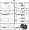
- FIG. 3 shows views showing results of simulating temperature distributions of the incoming species using the CFD in the conventional Claus burner shown in FIG. 1 .
- FIG. 3 shows that even when the flow rates of combustion air and acid gas are changed while the pit vapor is introduced (Cases 05 - 07), a temperature deviation may exist at the cross section 02.
- a degree of uniformization of the flow rate distribution and temperature distribution is compared at the cross section 02 of the Claus burner shown in FIG. 1 .
- the degree of uniformization of the distribution is generally compared through a distribution factor defined as follows, and the lower the value, the more uniform the distribution.
- threshold values of flow rate distribution uniformity and temperature distribution uniformity for preventing degradation are set.
- Table 3 shows the flow rate (herein, also referred to as flow velocity) distribution and temperature distribution, measured at the cross section 02 of the Claus burner according to still another embodiment of a related art shown in FIG. 1 .
- the flow rate and temperature are measured using the CFD.
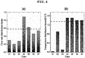
- FIGS. 4A and 4B are graphs of flow rate distribution factors and temperature distribution factors in Table 3, respectively.
- Case 07 corresponding to the operation condition at startup, the flow rate distribution factor and the temperature distribution factor each exist near an associated threshold value.
- the flow rate distribution factor and the temperature distribution factor have values near or exceeding an associated one of the threshold values.
- the case where the flow rate distribution factor and the temperature distribution factor are the largest is Case 04, and Case 04 is a case where the flow rate of the combustion air is the smallest when the pit vapor is introduced.
- an elbow may be formed at the outlet of the pit vapor pipe in order to ensure uniformity of the flow rate and temperature distribution in the front end surface for the combustion reaction.
- FIG. 5 is a schematic diagram of a Claus burner having a pit vapor pipe 5, in accordance with one specific embodiment of the present disclosure.
- An elbow 8 may be formed at the outlet of the pit vapor pipe 5 to inject the pit vapor toward the combustion air inlet 2.
- the combustion air inlet 2 is located in an upper part of the combustion air space part 6, and the combustion air may be introduced downward from the combustion air inlet 2.
- FIGS. 6A and 6B are sectional views of a Claus burner having the pit vapor pipe having an elbow, according to the one specific embodiment of the present disclosure.
- the elbow may be bent at a bending angle ⁇ in a range of 20° to 270° with respect to a cross section surface of the pit vapor pipe.
- the pit vapor becomes to face a wall of an inlet direction and may be dispersed after colliding with the wall.
- the pit vapor when the bending angle ⁇ is 20°, the pit vapor may move to a central part as shown in FIG. 6A rather than directly touching the hole where the acid gas is ejected.
- the bending angle ⁇ when the bending angle ⁇ is greater than 20°, the pit vapor may collide with an upper side wall or an opposite side wall, thereby generating an effect of decomposing the flow rate.
- the elbow may be inclined at an inclination angle ⁇ in a range of 0° to 90° with respect to a vertical direction of the pit vapor pipe.
- slits may be formed at the outlet of the pit vapor pipe in order to ensure uniformity of the flow rate distribution and temperature distribution of the flow in the front cross section of the combustion reaction resion.
- FIGS. 9A and 9B are schematic diagrams of the pit vapor pipe before and after including slits, respectively. That is, FIG. 9A of an upper figure is the pit vapor pipe not including the slits, and FIG. 9B of the lower figure is the pit vapor pipe including the slits.
- the pit vapor pipe is a straight type and has an end in a flow direction blocked, and a plurality of the slits may extend longitudinally from the end and may be formed along a circumference of the pit vapor pipe.
- a length of the slit may be in a range of about 50 mm to about 300 mm, about 50 mm to about 250 mm, about 50 mm to about 200 mm, about 50 mm to about 150 mm, about 50 mm to about 100 mm, about 100 mm to about 300 mm, about 150 mm to about 300 mm, about 200 mm to about 300 mm, about 250 mm to about 300 mm, or in all ranges and sub-ranges therebetween.
- a width of the slit may be in a range of about 5 mm to about 20 mm, about 5 mm to about 15 mm, about 5 mm to about 10 mm, about 10 mm to about 20 mm, about 15 mm to about 20 mm, or in all ranges and sub-ranges therebetween.
- the plurality of slits may be arranged in a range of 0° to 90°, 0° to 80°, 0° to 70°, 0° to 60°, 0° to 50°, 0° to 40°, 0° to 30°, 0° to 20°, 0° to 10°, 10° to 90°, 20° to 90°, 30° to 90°, 40° to 90°, 50° to 90°, 60° to 90°, 70° to 90°, 80° to 90°, or in all ranges and sub-ranges therebetween with respect to a vertical direction, thereby spraying the pit vapor upward.
- the number of slits may be in in a range of 1 to 20, 2 to 19, 3 to 18, 4 to 17, 5 to 16, 6 to 15, 7 to 14, 8 to 13, 9 to 12, 10 to 11, or in all ranges and sub-ranges therebetween.
- FIGS. 10A and 10B are schematic views of the Claus burner having the pit vapor pipe having no slits and the pit vapor pipe having the slits, respectively.
- the pit vapor may be injected into the Claus burner through the pit vapor pipe at a velocity of about 30 m/s.
- the pit vapor has a velocity maintained up to the combustion region, which may cause flame instability.
- FIG. 10B of the right side in the Claus burner having the pit vapor pipe in which the slits are formed, the pit vapor is discharged through the slits and mixed with the surrounding combustion air while spreading widely, whereby the velocity of the pit vapor is not maintained up to the flame generation area and may be reduced.
- Case 04 turndown (35%) case / having pit vapor
- Case 05 turndown case only with AAG / having pit vapor
- the Claus burners may be degraded by the flow rate and temperature deviations.
- flow rate control of the pit vapor may be performed (Cases 04-1 and 05-1), or the shape of the pit vapor pipe may be changed to include the slits (Case 04-Slit and 05-Slit).
- Table 4 below shows the flow rate of the incoming species in the cases (Cases 04-1 and 05-1) in which the flow rate control of the pit vapor is performed.
- a deflector may be formed at the outlet of the pit vapor pipe in order to ensure uniformity of the flow rate distribution and temperature distribution.
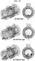
- FIGS. 14A to 14C are schematic diagrams of the respective pit vapor pipes.
- FIG. 14A is the conventional pit vapor pipe of a straight pipe type
- FIG. 14B is the pit vapor pipe of a cut pipe type cut at an angle of 30°
- FIG. 14C is the pit vapor pipe of a deflector type including the deflector.
- the deflector may include a head 11 installed spaced apart from the outlet of the pit vapor pipe so that the pit vapor supplied through the pit vapor pipe may be sprayed while colliding therewith and a plurality of support parts 10 extending from the outlet up to the head, of the pit vapor pipe.
- a width of each of the support parts may be in a range of about 5 mm to about 100 mm, about 10 mm to about 90 mm, about 20 mm to about 80 mm, about 30 mm to about 70 mm, about 40 mm to about 60 mm, or in in all ranges and sub-ranges therebetween.
- width means a shortest straight line distance between opposite side surfaces.
- a length of the support part may be in a range of about 100 mm to about 300 mm, about 100 mm to about 250 mm, about 100 mm to about 200 mm, about 100 mm to about 150 mm, about 150 mm to about 300 mm, about 200 mm to about 300 mm, about 250 mm to about 300 mm, or in all ranges and sub-ranges therebetween.
- the number of supports may be in a range of about 2 to 20, 4 to 18, 6 to 16, 8 to 14, 10 to 12, or in all ranges and sub-ranges therebetween.
- the pit vapor pipe having the deflector may prevent a phenomenon that the pit vapor plugs the slit.
- FIGS. 15A to 15C are schematic diagrams of the Claus burners installed with the various pit vapor pipes therein, respectively.
- FIG. 15A is the Claus burner having the conventional straight type pipe
- FIG. 15B is the Claus burner having the cut type pipe cutting the outlet at an angle of 30°
- FIG. 15C is the Claus burner having the pipe including the deflector.
- the pit vapor may be injected into the Claus burner through the pit vapor pipe at a velocity of about 30 m/s.
- the pit vapor has a velocity maintained up to the combustion region, which may cause flame instability.
- the pit vapor injected through the pit vapor pipe of the cut pipe type shows a flow pattern almost similar to that of the conventional pit vapor pipe of the straight pipe type.
- the flow of the pit vapor is blocked by the head of the deflector, discharged through the holes in the side surface, spreads widely, and mixed with the surrounding combustion air so that the velocity of the pit vapor shows a decreasing pattern without reaching the flame generation area.
- the elbow according to the present disclosure is applied to the pit vapor pipe for the case into which the pit vapor is introduced (Case 02) and the case having the largest flow rate deviation and temperature deviation (Case 04).
- FIG. 7 shows views showing flow rate distributions and temperature distributions in the Claus burner to which the elbow is applied to an end of the pit vapor pipe.
- the pit vapor is not directly introduced into the combustion region, but moves upward, and then moves to the combustion region.
- the flow rate deviation and temperature deviation exist in an upper region of cross section 02, but overall, it is shown that the deviations tend to be moderated.
- Table 5 shows values of the flow rate distribution and the temperature distribution in the Claus burner when the elbow is applied to the pit vapor pipe according to Example 1.
- Conventional art Improved (Example 1) Case 02 Case 04 Case 02 Case 04 flow rate Distribution Mean 16.69 5.78 16.91 5.90 Standard Deviation 3.51 5.17 3.61 3.11 Deviation/Mea n 0.21 0.89 0.21 0.53 Temperature Mean 392.1 389.5 391.9 392.9 Distribution Standard Deviation 3.529 6.014 0.791 2.649 Deviation/Mea n 9.0e-3 1.5e-2 2.0e-3 6.7e-3
- FIGS. 8A and 8B are flow rate distribution factors and temperature distribution factors, respectively, in the Claus burner when the elbow is applied to the pit vapor pipe according to Example 1.
- a deviation improvement effect is about 40% in terms of flow rate and about 55% in terms of temperature.
- the flow rate and the deviations of the flow rate have values near or above the threshold values. It appears that such a deviation is difficult to improve only by increasing the flow rate of combustion air.
- the elbow is applied to the pit vapor pipe outlet (that is, end part), in both the design operation and the turndown operation, it is observed the effect that the deviation is improved, that is, reduced. Accordingly, the Claus burner may be stably operated without an occurrence of backfire.
- FIG. 11 shows views comparing the flow rate distributions using the CFD in the Claus burner applied with the slits at the outlet of the pit vapor pipe.
- FIG. 12 shows views comparing the temperature distributions using the CFD in the Claus burner having the pit vapor pipe applied with the slits.
- Table 6 shows values of the flow rate distribution and the temperature distribution in the Claus burner when the slits are applied to the pit vapor pipe according to Example 2.
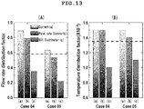
- FIGS. 13A and 13B are graphs of flow rate distribution factors and temperature distribution factors, respectively, in the Claus burner when the slits are applied to the pit vapor pipe according to Example 2.
- Case 04 (turndown (35%) case / having pit vapor)
- the deflector according to the present disclosure is applied to the outlet of the pit vapor pipe.
- FIGS. 16A to 16C are views comparing flow rate distributions and temperature distributions using the CFD in the Claus burner having the pit vapor pipe applied with the deflector.
- the flow rate deviation increases at the lower part of the burner.
- the pit vapor pipe of the cut pipe type in FIG. 16B it appears the flow pattern similar to that of the conventional pit vapor pipe of the pipe type in FIG. 16A , and there is little change in the deviation.
- the pit vapor pipe of the deflector pipe type in FIG. 16C it is confirmed that the flow rate deviation of the pit vapor concentrated in the lower part of the burner is alleviated.
- Table 7 shows the values of the flow rate distribution and the temperature distribution in the Claus burner when the deflector is applied to the pit vapor pipe according to Example 3.
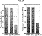
- Cases (a)Conventional Pipe (b)Cut pipe (c)Deflector Pipe Flow rate Distribution Mean 5.78 5.76 5.75 Standard Deviation 5.17 4.99 1.74 Deviation /Mean 0.89 0.87 0.30 Temperature Distribution Mean 389.5 389.6 393.4 Standard Deviation 6.014 5.967 3.725 Deviation /Mean 1.5e-2 1.5e-2 9.5e-3
- FIGS. 17A and 17B are graphs showing the flow rate distribution factors and temperature distribution factors, respectively, in each Claus burner having an associated one of the various pit vapor pipes including the pit vapor pipe applied with the deflector.
Landscapes
- Engineering & Computer Science (AREA)
- Chemical & Material Sciences (AREA)
- General Engineering & Computer Science (AREA)
- Mechanical Engineering (AREA)
- Combustion & Propulsion (AREA)
- Organic Chemistry (AREA)
- Chemical Kinetics & Catalysis (AREA)
- Environmental & Geological Engineering (AREA)
- Inorganic Chemistry (AREA)
- Oil, Petroleum & Natural Gas (AREA)
- General Chemical & Material Sciences (AREA)
- Analytical Chemistry (AREA)
- Biomedical Technology (AREA)
- Health & Medical Sciences (AREA)
- Pre-Mixing And Non-Premixing Gas Burner (AREA)
- Incineration Of Waste (AREA)
Abstract
Description
- The present application claims priority to
Korean Patent Application No. 10-2021-0039866, filed March 26, 2021 - The present disclosure relates to a Claus burner having a pit vapor pipe.
- As regulations related to the emission of air pollutants are strengthened, it is necessary to reduce concentrations of H2S and SO2 emitted into the atmosphere. An amount of a sulfur component emitted to the atmosphere is reduced by converting H2S and SO2 to elemental sulfur. As a technique for reducing H2S and SO2, a modified Claus process is known.
- The modified Claus process is based on the following two reactions.
[Reaction equation 1] H2S + 3/2O2 ↔ SO2 + H2O
-
Reaction equation 1 is a reaction in which hydrogen sulfide H2S is burned in a Claus burner to oxidize to sulfur dioxide SO2.
[Reaction equation 2] 2H2S + SO2 ↔ 3S + 2H2O
-
Reaction equation 2 is the so-called Claus reaction converting sulfur dioxide and residual hydrogen sulfide to elemental sulfur. - The Claus reaction for the conversion of hydrogen sulfide and sulfur dioxide to elemental sulfur is carried out using several catalytic reactors being continued. The more catalytic reactors go through, the more elemental sulfur may be recovered.
- Not all sulfur may be recovered by a continuous Claus catalytic reactor alone. A small amount of hydrogen sulfide remains in a tail gas stream, thereby being applied to a further step of tail gas purification (hereinafter referred to as "TGCU").
- In a sulfur recovery unit (SRU) using such a Claus reaction, the Claus burner carries out, without a separate fuel injection used as a heat source except for initial ignition, a combustion reaction of an acid gas containing the hydrogen sulfide incoming from an Amine Process or a Sour Water Stripping Process and oxygen in combustion air.
- Therefore, in the Claus burner, how ideally the acid gas and combustion air are mixed is the most important design factor in the Claus burner.
- On the other hand, the SRU produces liquid sulfur, and such liquid sulfur is typically in a form not being degassed. The liquid sulfur is introduced into a liquid sulfur pit.
- In
US Pat. No. 8,679,448 , liquid sulfur pits are agitated with a sweep gas such as air. In addition, a portion of the liquid sulfur from the liquid sulfur pit is degassed, the degassed liquid sulfur is properly stored or transported, and the gas comprising the purged hydrogen sulfide is recycled to the sulfur recovery unit. - Additional gas (hereinafter referred to as pit vapor) containing hydrogen sulfide introduced from the liquid sulfur pit often causes problems in combustion air control in the Claus burner of sulfur recovery units.
- In particular, during a regular maintenance period, when a Claus burner is in a turndown operation, the inflow of the pit vapor into the Claus burner causes flow rate deviation in the existing acid gas stream and combustion air stream. Such a flow deviation often causes a backfire at the tip of the pit vapor in the Claus burner.
- The foregoing is intended merely to aid in the understanding of the background of the present disclosure, and is not intended to mean that the present disclosure falls within the purview of the related art that is already known to those skilled in the art.
- Accordingly, the present disclosure has been made keeping in mind the above problems occurring in the related art, and the present disclosure is intended to provide a Claus burner having a pit vapor pipe to reduce a variation in a flow rate of pit vapor flowing into the Claus burner to no greater than a threshold value.
- In order to achieve the above objective, according to one aspect of the present disclosure, there may be provided a Claus burner having a pit vapor pipe, the Claus burner including: a combustion air space part having a pit vapor inlet, a combustion air inlet, and a fuel inlet; a pit vapor pipe extending from the pit vapor inlet to an inside of the combustion air space part; and an acid gas space part having an acid gas inlet and a mixed gas outlet and being in fluid communication with the combustion air space part, wherein, the mixed gas may include combustion air, pit vapor, and acid gas, and at an end of the pit vapor pipe, at least one part selected from a group consisting of an elbow, a deflector, and a plurality of slits is formed in order to spray the pit vapor into the combustion air space part.
- According to the specific exemplary embodiment, the pit vapor pipe may have a diameter of 5 cm to 25 cm.
- According to the specific exemplary embodiment, a longitudinal direction of the pit vapor pipe may be parallel to a direction from the combustion air space part to the acid gas space part.
- According to the specific exemplary embodiment, the combustion air inlet may be located in an upper part of the combustion air space part, and the combustion air may be introduced downward from the combustion air inlet.
- According to the specific exemplary embodiment, the elbow may be bent at an angle (θ) in a range of 20° to 270° with respect to a cross section surface and may be inclined at an angle (ϕ) in a range of 0° to 90° with respect to a vertical direction, of the pit vapor pipe.
- According to the specific exemplary embodiment, the plurality of slits may be arranged along a circumference of the pit vapor pipe, and the end in a longitudinal direction of the pit vapor pipe may be blocked.
- According to the specific exemplary embodiment, the plurality of slits may be arranged in a range of 0° to 90° with respect to a vertical direction.
- According to the specific exemplary embodiment, the slit may have a width of 5 mm to 20 mm.
- According to the specific exemplary embodiment, the deflector may include: a head installed spaced apart from the outlet of the pit vapor pipe so that the pit vapor supplied through the pit vapor pipe may be sprayed while colliding therewith; and a plurality of support parts extending from the outlet up to the head, of the pit vapor pipe.
- According to the specific exemplary embodiment, each of the support parts may have a width of 5 mm to 20 mm.
- According to the specific exemplary embodiment, the mixed gas may further include fuel.
- As described above, the present disclosure has the advantage that, when the pit vapor flows into the Claus burner, particularly even when the sulfur recovery unit is in a turndown operation, pit vapor can be treated in the Claus burner without backfire.
- The above and other obj ectives, features, and other advantages of the present disclosure will be more clearly understood from the following detailed description when taken in conjunction with the accompanying drawings, in which:
-
FIG. 1 is a schematic diagram of a Claus burner having a conventional pit vapor pipe; -
FIG. 2 shows views showing results of simulating flow velocity distributions of incoming species using computational fluid dynamics (CFD) in the conventional Claus burner shown inFIG. 1 ; -
FIG. 3 shows views showing results of simulating temperature distributions of the incoming species using the CFD in the conventional Claus burner shown inFIG. 1 ; -
FIGS. 4A and 4B are graphs of flow rate distribution factors and temperature distribution factors, respectively, measured in still another specific embodiment of the Claus burner shown inFIG. 1 ; -
FIG. 5 is a schematic diagram of a Claus burner having a pit vapor pipe, in accordance with one specific embodiment of the present disclosure; -
FIGS. 6A and 6B are sectional views of a Claus burner having the pit vapor pipe having an elbow, according to the one specific embodiment of the present disclosure; -
FIG. 7 shows views showing flow rate distributions and temperature distributions in the Claus burner to which the elbow is applied to an end of the pit vapor pipe; -
FIGS. 8A and 8B are flow rate distribution factors and temperature distribution factors, respectively, in the Claus burner when the elbow is applied to the pit vapor pipe according to the present disclosure; -
FIGS. 9A and 9B are schematic diagrams of the pit vapor pipe before and after including slits, respectively; -
FIGS. 10A and 10B are schematic views of the Claus burner having the pit vapor pipe having no slits and the pit vapor pipe having the slits, respectively; -
FIG. 11 shows views comparing the flow rate distributions using the CFD in the Claus burner applied with the slits at the outlet of the pit vapor pipe; -
FIG. 12 shows views comparing the temperature distributions using the CFD in the Claus burner having the pit vapor pipe applied with the slits; -
FIGS. 13A and 13B are graphs of flow rate distribution factors and temperature distribution factors, respectively, in the Claus burner when the slits are applied to the pit vapor pipe; -
FIGS. 14A to 14C are schematic diagrams of the pit vapor pipes including one having the deflector; -
FIGS. 15A to 15C are schematic diagrams of the Claus burners installed with the various pit vapor pipes therein, respectively; -
FIGS. 16A to 16C are views comparing flow rate distributions and temperature distributions using the CFD in the Claus burner having the pit vapor pipe applied with the deflector; and -
FIGS. 17A and 17B are graphs showing the flow rate distribution factors and temperature distribution factors, respectively, in each Claus burner having an associated one of the various pit vapor pipes including the pit vapor pipe applied with the deflector. - The present disclosure may all be achieved by the following description. It is to be understood that the following description describes exemplary embodiments of the present disclosure, but the present disclosure is not necessarily limited thereto. In addition, it should be understood that the accompanying drawings are provided to aid understanding, but the present disclosure is not limited thereto.
-
FIG. 1 is a schematic diagram of a Claus burner having a conventional pit vapor pipe. - In the present disclosure, "pit vapor" means a gas containing hydrogen sulfide produced by degassing liquid sulfur from liquid sulfur pits.
- In the present disclosure, an outlet of a pit vapor pipe and an end of the pit vapor pipe are used interchangeably.
- With reference to
FIG. 1 , there is shown aClaus burner 1 in which oxygen in combustion air and acid gas react to cause a combustion reaction. TheClaus burner 1 includes: a combustionair space part 6 having acombustion air inlet 2; an acidgas space part 7 having anacid gas inlet 3 and being in fluid communication with the combustionair space part 6; and a pit vapor pipe 5 arranged inside the combustionair space part 6 in a direction from the combustionair space part 6 to the acidgas space part 7. - In one specific embodiment, the
Claus burner 1 includes a fuel inlet 4 in the combustionair space part 6 and/or the acidgas space part 7. - In the one specific embodiment, acid gas includes amine acid gas. For example, the amine acid gas may be produced by treating sour gas by an amine gas treatment process, and this is known in the art. In another specific embodiment, the acid gas includes sour water stripper acid gas. The acid gas generally includes at least 5 mole percent hydrogen sulfide and may include up to about 80 to 95 mole percent hydrogen sulfide. The amine acid gas may include other gases such as carbon dioxide, water vapor, ammonia, other impurities, and the like but is not limited thereto.
- A mixture of the combustion air, acid gas, and pit vapor is combusted in the
Claus burner 1 and discharged into a thermal reactor (not shown) where a reaction of a Claus process takes place. - In the Claus burner, especially in the case of a turndown operation of the Claus burner, uniform mixing of the combustion air, acid gas, pit vapor, and optionally fuel is important in order to avoid backfire due to an inflow of the pit vapor.
- In the present specification, the turndown operation refers to a case in which a flow rate of the combustion air, acid gas, and the like to the Claus reactor, compared to an operation case initially designed (design case), is reduced by no greater than about 30%, about 35%, or about 40%.
- In one or more specific embodiments, the operation of Claus burners may take into account the cases shown in Table 1.
[Table 1] Cases Operation methods Case 01 Design case / having no pit vapor Case 02 Design case / having pit vapor Case 03 Turndown (35%) case / having no pit vapor Case 04 Turndown (35%) case / having pit vapor Case 05 Turndown case only with 1) AAG / having pit vapor Case 06 3000 Nm3/hr case only with AAG / having pit vapor Case 07 3500 Nm3/hr case only with AAG / having pit vapor - As shown in Table 2 below, the
Cases Case 02, and there are differences in absolute flow rates and flow rate ratios of the air and AAG in each case above. - In each case, constituents and flow rates of the incoming species are shown in Table 2.
[Table 2] Incoming species Case 01 Case 02Case 03Case 04Case 05Case 06Case 07Combustion air (kg/h) N2 15150.0 4 13766.4 4 5302.5 1 3918.9 1 5510.2 7 7274.7 9 6352.7 7 O2 4597.12 4177.28 1608.9 9 1189.1 5 1672.0 3 2207.4 5 1927.6 8 H2O 660.25 599.95 231.08 170.79 240.14 317.04 276.86 Total 20407.4 2 18543.6 7 7142.5 9 5278.8 5 7422.4 5 9799.2 9 8557.3 2 Acid gas (kg/h) H2O 449.22 449.22 157.22 157.22 85.08 124.73 145.52 NH3 555.96 555.96 194.58 194.58 0.95 1.39 1.63 H2S 1876.10 1876.10 656.63 656.63 2946.2 1 4319.4 0 5039.3 0 Total 2881.28 2881.28 1008.4 5 1008.4 5 3032.2 5 4445.5 4 5186.4 6 Fuel (kg/h) H2 117.15 116.25 45.06 Total 117.15 116.25 45.06 Pit vapor (kg/h) N2 1382.57 1382.5 7 1382.5 7 1382.5 7 1382.5 7 O2 419.84 419.84 419.84 419.84 419.84 H2O 61.61 61.61 61.61 61.61 61.61 H2S 5.79 5.79 5.79 5.79 5.79 Total 1869.82 1869.8 2 1869.8 2 1869.8 2 1869.8 2 -
FIG. 2 shows views showing results of simulating distributions of flow velocity (herein, also referred to as flow rate) of incoming species using computational fluid dynamics (CFD) in the conventional Claus burner shown inFIG. 1 . - In
FIG. 2 , across section 01 is a cross section in a longitudinal direction of the Claus burner, and across section 02 is a cross section in a transverse direction of the Claus burner between the combustion air inlet and the acid gas inlet. - As a result of comparing the flow rate distributions in the
cross section 02 ofFIG. 2 , in the cases of the design operation (Cases 01 and 02), a deviation of the flow rates is not large regardless of the inflow of the pit vapor. With reference toFIG. 2 , even in the cases of the turndown operation, when the pit vapor does not flow in (Case 03), the flow rate deviation is not large, but, when the pit vapor flows in (Case 04), the flow rate deviation increases. Even when the flow rates of combustion air and acid gas are changed while the pit vapor is introduced (Cases 05 - 07), a flow rate deviation exists at thecross section 02. - Consequentially,
FIG. 2 shows that, when the pit vapor is introduced, the flow rate of the combustion air may need to be no less than a certain amount in order to improve the flow rate deviation at a front end of a combustion region (Cross section 02). - In the present specification, the combustion region and a flame generation area are the same region and may be used interchangeably.
- In the one specific embodiment, the thermal reactor may be located downstream of the Claus burner. Accordingly, a partial region of the part where the thermal reactor is connected to the Claus burner may correspond to the combustion region.
- In the one specific embodiment, a combustion region may start from the vicinity of a hole through which the acid gas is introduced.
-
FIG. 3 shows views showing results of simulating temperature distributions of the incoming species using the CFD in the conventional Claus burner shown inFIG. 1 . - As a result of comparing the temperature distributions in the
cross section 02 ofFIG. 3 , in the cases of the design operation (Cases 01 and 02), a deviation of the temperature is not large regardless of the inflow of the pit vapor. Even in the cases of the turndown operation, when the pit vapor does not flow in (Case 03), the temperature deviation is not large, but, when the pit vapor flows in (Case 04), the temperature deviation increases.FIG. 3 shows that even when the flow rates of combustion air and acid gas are changed while the pit vapor is introduced (Cases 05 - 07), a temperature deviation may exist at thecross section 02. - For quantification of the flow rate distribution and temperature distribution, a degree of uniformization of the flow rate distribution and temperature distribution is compared at the
cross section 02 of the Claus burner shown inFIG. 1 . - The degree of uniformization of the distribution is generally compared through a distribution factor defined as follows, and the lower the value, the more uniform the distribution.
- Through analyses and experimental results for the conventional Claus burner shown in
FIG. 1 , threshold values of flow rate distribution uniformity and temperature distribution uniformity for preventing degradation are set. - Table 3 below shows the flow rate (herein, also referred to as flow velocity) distribution and temperature distribution, measured at the
cross section 02 of the Claus burner according to still another embodiment of a related art shown inFIG. 1 . In the present specification, the flow rate and temperature are measured using the CFD.FIGS. 4A and 4B are graphs of flow rate distribution factors and temperature distribution factors in Table 3, respectively.[Table 3] Cases 01 02 03 04 05 06 07 Flow rate Distribution Mean 16.42 16.69 5.68 5.78 7.51 9.48 8.45 Standard deviation 4.85 3.51 1.61 5.17 4.73 4.38 4.54 Mean/ Standard deviation 0.30 0.21 0.28 0.89 0.63 0.46 0.54 Temperature Distribution Mean 389.7 392.1 387.7 389.5 390.4 391.0 390.7 Standard deviation 0.177 3.529 0.433 6.014 5.689 5.398 5.534 Mean/ Standard deviation 4.5e-4 9.0e-3 1.1e-3 1.5e-2 1.5e-2 1.4e-2 1.4e-2 - Among the cases shown in
FIGS. 4A and 4B , when the flow rate distribution factor value exceeded 0.58, or the temperature distribution factor value exceeded 1.3×10⁻², damage to the Claus burner occurs. - With reference to Table 3 and
FIGS. 4A and 4B , inCase 07 corresponding to the operation condition at startup, the flow rate distribution factor and the temperature distribution factor each exist near an associated threshold value. In addition, when the pit vapor is introduced, in all the cases where the flow rate of combustion air decreases, the flow rate distribution factor and the temperature distribution factor have values near or exceeding an associated one of the threshold values. The case where the flow rate distribution factor and the temperature distribution factor are the largest isCase 04, andCase 04 is a case where the flow rate of the combustion air is the smallest when the pit vapor is introduced. - As discussed above, as a result of considering the Claus burner according to the related art, for a stable operation in which the backfire does not occur, uniformity of the flow rate and temperature needs to be ensured at a front end surface (that is, cross section 02) where the combustion reaction occurs. A cause of the deviation in the flow rate and temperature is shown to be due to the fast inflow rate of the pit vapor. Moreover, when the pit vapor is introduced during the turndown operation, it appears that it is difficult to improve the fluctuations in the flow rate and temperature inside the Claus burner only by adjusting the combustion air flow rate.
- Accordingly, according to the one specific embodiment of the present disclosure, an elbow may be formed at the outlet of the pit vapor pipe in order to ensure uniformity of the flow rate and temperature distribution in the front end surface for the combustion reaction.
-
FIG. 5 is a schematic diagram of a Claus burner having a pit vapor pipe 5, in accordance with one specific embodiment of the present disclosure. Anelbow 8 may be formed at the outlet of the pit vapor pipe 5 to inject the pit vapor toward thecombustion air inlet 2. - In the one specific embodiment, the
combustion air inlet 2 is located in an upper part of the combustionair space part 6, and the combustion air may be introduced downward from thecombustion air inlet 2. -
FIGS. 6A and 6B are sectional views of a Claus burner having the pit vapor pipe having an elbow, according to the one specific embodiment of the present disclosure. With reference toFIG. 6A of the left side, the elbow may be bent at a bending angle θ in a range of 20° to 270° with respect to a cross section surface of the pit vapor pipe. - In the one specific embodiment, when the bending angle θ is 270°, the pit vapor becomes to face a wall of an inlet direction and may be dispersed after colliding with the wall.
- In the one specific embodiment, when the bending angle θ is 20°, the pit vapor may move to a central part as shown in
FIG. 6A rather than directly touching the hole where the acid gas is ejected. In addition, when the bending angle θ is greater than 20°, the pit vapor may collide with an upper side wall or an opposite side wall, thereby generating an effect of decomposing the flow rate. - In addition, with reference to
FIG. 6B of the right side, the elbow may be inclined at an inclination angle ϕ in a range of 0° to 90° with respect to a vertical direction of the pit vapor pipe. - When the inclination angle ϕ is 0°, it has an effect of colliding with the upper side wall to distribute the flow rate, and as it approaches 90°, it is possible to form a spiral flow flowing along a cylinder.
- According to still another specific embodiment of the present disclosure, slits may be formed at the outlet of the pit vapor pipe in order to ensure uniformity of the flow rate distribution and temperature distribution of the flow in the front cross section of the combustion reaction resion.
-
FIGS. 9A and 9B are schematic diagrams of the pit vapor pipe before and after including slits, respectively. That is,FIG. 9A of an upper figure is the pit vapor pipe not including the slits, andFIG. 9B of the lower figure is the pit vapor pipe including the slits. - In the one specific embodiment, the pit vapor pipe is a straight type and has an end in a flow direction blocked, and a plurality of the slits may extend longitudinally from the end and may be formed along a circumference of the pit vapor pipe.
- In one or more specific embodiments, a length of the slit may be in a range of about 50 mm to about 300 mm, about 50 mm to about 250 mm, about 50 mm to about 200 mm, about 50 mm to about 150 mm, about 50 mm to about 100 mm, about 100 mm to about 300 mm, about 150 mm to about 300 mm, about 200 mm to about 300 mm, about 250 mm to about 300 mm, or in all ranges and sub-ranges therebetween.
- In one or more specific embodiments, a width of the slit may be in a range of about 5 mm to about 20 mm, about 5 mm to about 15 mm, about 5 mm to about 10 mm, about 10 mm to about 20 mm, about 15 mm to about 20 mm, or in all ranges and sub-ranges therebetween.
- In one or more specific embodiments, the plurality of slits may be arranged in a range of 0° to 90°, 0° to 80°, 0° to 70°, 0° to 60°, 0° to 50°, 0° to 40°, 0° to 30°, 0° to 20°, 0° to 10°, 10° to 90°, 20° to 90°, 30° to 90°, 40° to 90°, 50° to 90°, 60° to 90°, 70° to 90°, 80° to 90°, or in all ranges and sub-ranges therebetween with respect to a vertical direction, thereby spraying the pit vapor upward.
- In one or more specific embodiments, the number of slits may be in in a range of 1 to 20, 2 to 19, 3 to 18, 4 to 17, 5 to 16, 6 to 15, 7 to 14, 8 to 13, 9 to 12, 10 to 11, or in all ranges and sub-ranges therebetween.
-
FIGS. 10A and 10B are schematic views of the Claus burner having the pit vapor pipe having no slits and the pit vapor pipe having the slits, respectively. - Because a diameter (about 6") of the pit vapor pipe is small compared to the flow rate, the pit vapor may be injected into the Claus burner through the pit vapor pipe at a velocity of about 30 m/s. As shown in
FIG. 10A of the left side, in the Claus burner having the conventional pit vapor pipe of a straight pipe type, the pit vapor has a velocity maintained up to the combustion region, which may cause flame instability. However, as shown inFIG. 10B of the right side, in the Claus burner having the pit vapor pipe in which the slits are formed, the pit vapor is discharged through the slits and mixed with the surrounding combustion air while spreading widely, whereby the velocity of the pit vapor is not maintained up to the flame generation area and may be reduced. - As described above, in Case 04 (turndown (35%) case / having pit vapor) and Case 05 (turndown case only with AAG / having pit vapor), when the pit vapor is injected, the Claus burners may be degraded by the flow rate and temperature deviations.
- To improve the flow rate and temperature deviations, flow rate control of the pit vapor may be performed (Cases 04-1 and 05-1), or the shape of the pit vapor pipe may be changed to include the slits (Case 04-Slit and 05-Slit).
- Table 4 below shows the flow rate of the incoming species in the cases (Cases 04-1 and 05-1) in which the flow rate control of the pit vapor is performed.
[Table 4] Incoming species Case 04 Case 05Case 04-1 Case 05-1 Case 04-Slit Case 05-Slit Combustion air (kg/h) N2 3918.91 5510.27 3918.91 5510.27 3918.91 5510.27 O2 1189.15 1672.03 1189.15 1672.03 1189.15 1672.03 H2O 170.79 240.14 170.79 240.14 170.79 240.14 Total 5278.85 7422.45 5278.85 7422.45 5278.85 7422.45 Acid gas (kg/h) H2O 157.22 85.08 157.22 85.08 157.22 85.08 NH3 194.58 0.95 194.58 0.95 194.58 0.95 H2S 656.63 2946.21 656.63 2946.21 656.63 2946.21 Total 1008.45 3032.25 1008.45 3032.25 1008.45 3032.25 Fuel (kg/h) H2 117.15 117.15 117.15 Total 117.15 117.15 117.15 Pit vapor (kg/h) N2 1382.57 1382.57 1243.94 1243.94 1382.57 1382.57 O2 419.84 419.84 377.74 377.74 419.84 419.84 H2O 61.61 61.61 25.23 25.23 61.61 61.61 H2S 5.79 5.79 5.79 5.79 5.79 5.79 Total 1869.82 1869.82 1652.70 1652.70 1869.82 1869.82 - According to still another specific embodiment of the present disclosure, a deflector may be formed at the outlet of the pit vapor pipe in order to ensure uniformity of the flow rate distribution and temperature distribution.
-
FIGS. 14A to 14C are schematic diagrams of the respective pit vapor pipes. Specifically,FIG. 14A is the conventional pit vapor pipe of a straight pipe type,FIG. 14B is the pit vapor pipe of a cut pipe type cut at an angle of 30°, andFIG. 14C is the pit vapor pipe of a deflector type including the deflector. - In the one specific embodiment, with reference to
FIG. 14C , the deflector may include ahead 11 installed spaced apart from the outlet of the pit vapor pipe so that the pit vapor supplied through the pit vapor pipe may be sprayed while colliding therewith and a plurality ofsupport parts 10 extending from the outlet up to the head, of the pit vapor pipe. - In one or more specific embodiments, a width of each of the support parts may be in a range of about 5 mm to about 100 mm, about 10 mm to about 90 mm, about 20 mm to about 80 mm, about 30 mm to about 70 mm, about 40 mm to about 60 mm, or in in all ranges and sub-ranges therebetween.
- In the present specification, "width" means a shortest straight line distance between opposite side surfaces.
- In one or more specific embodiments, a length of the support part may be in a range of about 100 mm to about 300 mm, about 100 mm to about 250 mm, about 100 mm to about 200 mm, about 100 mm to about 150 mm, about 150 mm to about 300 mm, about 200 mm to about 300 mm, about 250 mm to about 300 mm, or in all ranges and sub-ranges therebetween.
- In one or more specific embodiments, the number of supports may be in a range of about 2 to 20, 4 to 18, 6 to 16, 8 to 14, 10 to 12, or in all ranges and sub-ranges therebetween.
- The pit vapor pipe having the deflector may prevent a phenomenon that the pit vapor plugs the slit.
-
FIGS. 15A to 15C are schematic diagrams of the Claus burners installed with the various pit vapor pipes therein, respectively. Specifically,FIG. 15A is the Claus burner having the conventional straight type pipe,FIG. 15B is the Claus burner having the cut type pipe cutting the outlet at an angle of 30°, andFIG. 15C is the Claus burner having the pipe including the deflector. - Because a diameter (about 6") of the pit vapor pipe is small compared to the flow rate, the pit vapor may be injected into the Claus burner through the pit vapor pipe at a velocity of about 30 m/s.
- As shown in
FIG. 15A , in the Claus burner having the conventional pit vapor pipe of the straight pipe type, the pit vapor has a velocity maintained up to the combustion region, which may cause flame instability. As shown inFIG. 15B , the pit vapor injected through the pit vapor pipe of the cut pipe type shows a flow pattern almost similar to that of the conventional pit vapor pipe of the straight pipe type. In the case of the pit vapor pipe of the deflector type shown inFIG. 15C , the flow of the pit vapor is blocked by the head of the deflector, discharged through the holes in the side surface, spreads widely, and mixed with the surrounding combustion air so that the velocity of the pit vapor shows a decreasing pattern without reaching the flame generation area. - Hereinafter, the present disclosure will be described in more detail through examples, but the scope of the present disclosure is not limited to the following examples.
- Of the design cases, the elbow according to the present disclosure is applied to the pit vapor pipe for the case into which the pit vapor is introduced (Case 02) and the case having the largest flow rate deviation and temperature deviation (Case 04).
-
FIG. 7 shows views showing flow rate distributions and temperature distributions in the Claus burner to which the elbow is applied to an end of the pit vapor pipe. With reference toFIG. 7 , In the Claus burner according to Example 1, the pit vapor is not directly introduced into the combustion region, but moves upward, and then moves to the combustion region. In bothCases cross section 02, but overall, it is shown that the deviations tend to be moderated. - Table 5 shows values of the flow rate distribution and the temperature distribution in the Claus burner when the elbow is applied to the pit vapor pipe according to Example 1.
[Table 5] Conventional art Improved (Example 1) Case 02Case 04Case 02Case 04flow rate Distribution Mean 16.69 5.78 16.91 5.90 Standard Deviation 3.51 5.17 3.61 3.11 Deviation/Mea n 0.21 0.89 0.21 0.53 Temperature Mean 392.1 389.5 391.9 392.9 Distribution Standard Deviation 3.529 6.014 0.791 2.649 Deviation/Mea n 9.0e-3 1.5e-2 2.0e-3 6.7e-3 -
FIGS. 8A and 8B are flow rate distribution factors and temperature distribution factors, respectively, in the Claus burner when the elbow is applied to the pit vapor pipe according to Example 1. - With reference to Table 5 and
FIGS. 8A and 8B , inCase 04, when the elbow is applied, a deviation improvement effect is about 40% in terms of flow rate and about 55% in terms of temperature. - As discussed above, when the pit vapor is introduced during the turndown operation, the flow rate and the deviations of the flow rate have values near or above the threshold values. It appears that such a deviation is difficult to improve only by increasing the flow rate of combustion air. In the results of Example 1, when the elbow is applied to the pit vapor pipe outlet (that is, end part), in both the design operation and the turndown operation, it is observed the effect that the deviation is improved, that is, reduced. Accordingly, the Claus burner may be stably operated without an occurrence of backfire.
- For Case 04 (turndown (35%) case / having pit vapor) and Case 05 (turndown case only with AAG / having pit vapor), slits according to the present disclosure are applied to the outlet of the pit vapor pipe.
-
FIG. 11 shows views comparing the flow rate distributions using the CFD in the Claus burner applied with the slits at the outlet of the pit vapor pipe. - With reference to
FIG. 11 , inCases Case 05, unlikeCase 04, the acid gas is introduced, but this does not affect the flow rate deviation at the front end of the combustion region. In the case of flow rate control, it exhibits an effect of improving the flow rate deviation compared to the case of the current state, but as a phenomenon arises such that the flow rate is concentrated in the lower part of the burner, the deviation appears incross section 02. However, when the pit vapor pipe including the slits is applied, it is confirmed that the flow rate, which has been concentrated in the lower part of the burner, shows a phenomenon in which the deviation thereof is alleviated. -
FIG. 12 shows views comparing the temperature distributions using the CFD in the Claus burner having the pit vapor pipe applied with the slits. - With reference to
FIG. 12 , inCases Case 05, compared toCase 04, more acid gas is introduced, but this does not affect the temperature deviation in the front end of the combustion region. In the case of flow rate control, it exhibits an effect of improving the flow rate deviation compared to the case of the current state as is, but as a phenomenon arises such that the flow rate is concentrated in the lower part of the burner, the deviation appears incross section 02. When the pit vapor pipe formed with the slits is applied, it is confirmed that the flow rate, which has been concentrated in the lower part of the burner, shows a phenomenon in which the deviation thereof is alleviated. - Table 6 shows values of the flow rate distribution and the temperature distribution in the Claus burner when the slits are applied to the pit vapor pipe according to Example 2.
[Table 6] Cases 04 04-1 (flow rate control) 04- Slit 05 05-1 (flow rate control) 05-Slit Flow rate Distribution Mean 5.78 5.58 5.73 7.51 7.33 7.47 Standard Deviation 5.17 4.39 1.98 4.73 3.97 1.63 Deviation /Mean 0.89 0.79 0.35 0.63 0.54 0.22 Temperature Distribution Mean 389.5 389.4 393.1 390.4 390.3 393.0 Standard Deviation 6.014 5.961 4.050 5.689 5.641 4.204 Deviation /Mean 1.5e-2 1.5e-2 1.0e-2 1.5e-2 1.4e-2 1.1e-2 -
FIGS. 13A and 13B are graphs of flow rate distribution factors and temperature distribution factors, respectively, in the Claus burner when the slits are applied to the pit vapor pipe according to Example 2. - In
Case 04, even with flow rate control (Case 04-1), both the flow rate distribution factor and the temperature distribution factor have values above the respective threshold values. InCase 05, with flow rate control (Case 05-1), it is possible to improve the flow rate deviation, but the temperature deviation has a value above the threshold. However, when the slits are applied to the pit vapor pipe, both the flow rate distribution factor and temperature distribution factor may be lowered to have values below the respective threshold values. - In Case 04 (turndown (35%) case / having pit vapor), the deflector according to the present disclosure is applied to the outlet of the pit vapor pipe.
-
FIGS. 16A to 16C are views comparing flow rate distributions and temperature distributions using the CFD in the Claus burner having the pit vapor pipe applied with the deflector. In the case of the conventional pit vapor pipe of the pipe type inFIG. 16A , as the pit vapor is introduced, the flow rate deviation increases at the lower part of the burner. In the case of the pit vapor pipe of the cut pipe type inFIG. 16B , it appears the flow pattern similar to that of the conventional pit vapor pipe of the pipe type inFIG. 16A , and there is little change in the deviation. In the case of the pit vapor pipe of the deflector pipe type inFIG. 16C , it is confirmed that the flow rate deviation of the pit vapor concentrated in the lower part of the burner is alleviated. - Table 7 shows the values of the flow rate distribution and the temperature distribution in the Claus burner when the deflector is applied to the pit vapor pipe according to Example 3.
[Table 7] Cases (a)Conventional Pipe (b)Cut pipe (c)Deflector Pipe Flow rate Distribution Mean 5.78 5.76 5.75 Standard Deviation 5.17 4.99 1.74 Deviation /Mean 0.89 0.87 0.30 Temperature Distribution Mean 389.5 389.6 393.4 Standard Deviation 6.014 5.967 3.725 Deviation /Mean 1.5e-2 1.5e-2 9.5e-3 -
FIGS. 17A and 17B are graphs showing the flow rate distribution factors and temperature distribution factors, respectively, in each Claus burner having an associated one of the various pit vapor pipes including the pit vapor pipe applied with the deflector. - As shown in
FIGS. 17A and 17B , in the case of (b) cut pipe, there is little degree of improvement in deviation compared to (a) the conventional case. However, in the case of (c) deflector application, both the flow rate deviation and temperature deviation are able to be lowered to have values below the threshold values. - Although the present disclosure has been described in detail through specific embodiments, it is intended to describe the present disclosure in detail, and the present disclosure is not limited thereto. In addition, it is clear that modifications or improvements are possible by those of ordinary skill in the art within the technical spirit of the present disclosure.
- Simple modifications or changes of the present disclosure may be easily used by those of ordinary skill in the art, and all such modifications or changes may be considered to be included in the scope of the present disclosure.
Claims (11)
- A Claus burner having a pit vapor pipe and allowing a combustion reaction to be generated by reacting acid gas with oxygen in combustion air, the Claus burner comprising:a combustion air space part having a pit vapor inlet, a combustion air inlet, and a fuel inlet;a pit vapor pipe extending from the pit vapor inlet to an inside of the combustion air space part; andan acid gas space part having an acid gas inlet and a mixed gas outlet and being in fluid communication with the combustion air space part,wherein, the mixed gas comprises combustion air, pit vapor, and acid gas, andat an end of the pit vapor pipe, at least one part selected from a group consisting of an elbow, a deflector, and a plurality of slits is formed in order to spray the pit vapor into the combustion air space part.
- The Claus burner of claim 1, wherein the pit vapor pipe has a diameter of 5 cm to 25 cm.
- The Claus burner of claim 1, wherein a longitudinal direction of the pit vapor pipe is parallel to a direction from the combustion air space part to the acid gas space part.
- The Claus burner of claim 1, wherein the combustion air inlet is located in an upper part of the combustion air space part, and the combustion air is introduced downward from the combustion air inlet.
- The Claus burner of claim 1, wherein the elbow is bent at an angle (θ) in a range of 20° to 270° with respect to a cross section surface and is inclined at an angle (ϕ) in a range of 0° to 90° with respect to a vertical direction, of the pit vapor pipe.
- The Claus burner of claim 1, wherein the plurality of slits is arranged along a circumference of the pit vapor pipe, and the end in a longitudinal direction of the pit vapor pipe is blocked.
- The Claus burner of claim 6, wherein the plurality of slits is arranged in a range of 0° to 90° with respect to a vertical direction.
- The Claus burner of claim 6, wherein the slit has a width of 5 mm to 20 mm.
- The Claus burner of claim 1, wherein the deflector comprises:a head installed spaced apart from the outlet of the pit vapor pipe so that the pit vapor supplied through the pit vapor pipe is sprayed while colliding therewith; anda plurality of support parts extending from the outlet up to the head, of the pit vapor pipe.
- The Claus burner of claim 9, wherein each of the support parts has a width of 5 mm to 20 mm.
- The Claus burner of claim 1, the mixed gas further comprises fuel.
Applications Claiming Priority (1)
| Application Number | Priority Date | Filing Date | Title |
|---|---|---|---|
| KR1020210039866A KR102820067B1 (en) | 2021-03-26 | 2021-03-26 | Claus burner having pit vapor pipe |
Publications (3)
| Publication Number | Publication Date |
|---|---|
| EP4063322A2 true EP4063322A2 (en) | 2022-09-28 |
| EP4063322A3 EP4063322A3 (en) | 2022-10-05 |
| EP4063322B1 EP4063322B1 (en) | 2023-05-10 |
Family
ID=80930527
Family Applications (1)
| Application Number | Title | Priority Date | Filing Date |
|---|---|---|---|
| EP22163530.3A Active EP4063322B1 (en) | 2021-03-26 | 2022-03-22 | Claus burner having pit vapor pipe |
Country Status (4)
| Country | Link |
|---|---|
| EP (1) | EP4063322B1 (en) |
| JP (1) | JP2022151863A (en) |
| KR (1) | KR102820067B1 (en) |
| CN (1) | CN115121111A (en) |
Citations (1)
| Publication number | Priority date | Publication date | Assignee | Title |
|---|---|---|---|---|
| US8679448B2 (en) | 2011-09-21 | 2014-03-25 | Fluor Technologies Corporation | Configurations and methods of treatment of sulfur-containing vent gases |
Family Cites Families (14)
| Publication number | Priority date | Publication date | Assignee | Title |
|---|---|---|---|---|
| US3399970A (en) * | 1966-04-22 | 1968-09-03 | Pan American Petroleum Corp | Recovery of sulfur from sour gas by the split-flow process |
| US3873679A (en) * | 1973-05-29 | 1975-03-25 | Amoco Prod Co | Reheat method for use in sulfur recovery process |
| US3963443A (en) * | 1974-09-23 | 1976-06-15 | Ford, Bacon & Davis Texas Incorporated | Acid gas burner and sulfur recovery system |
| GB9314212D0 (en) * | 1993-07-09 | 1993-08-18 | Boc Group Plc | A gas combuster/reactor |
| JPH09124309A (en) * | 1995-10-30 | 1997-05-13 | Mitsubishi Kakoki Kaisha Ltd | Treatment of sulfur pit-extracted gas |
| DE19718261A1 (en) * | 1997-04-30 | 1998-11-05 | Messer Griesheim Gmbh | Method and device for converting hydrogen sulfide into elemental sulfur |
| KR100376619B1 (en) * | 2000-09-25 | 2003-03-19 | 두산중공업 주식회사 | Low Nitrogen Oxide Coal Firing Burner |
| EP2072899B1 (en) * | 2007-12-19 | 2016-03-30 | Alstom Technology Ltd | Fuel injection method |
| KR20120001186A (en) * | 2010-06-29 | 2012-01-04 | 두산중공업 주식회사 | Nozzle tip of coal burner |
| KR101278590B1 (en) * | 2012-06-27 | 2013-06-25 | 지에스건설 주식회사 | Claus burner for sulfur recovery process |
| US9624106B2 (en) * | 2015-08-14 | 2017-04-18 | Mahin Rameshni | Supersulf-a process with internal cooling and heating reactors in subdewpoint sulfur recovery and tail gas treating systems |
| CN206130978U (en) * | 2016-10-18 | 2017-04-26 | 洛阳新普石化设备开发有限公司 | Acid gas reaction boiler burner |
| US11807527B2 (en) * | 2019-05-03 | 2023-11-07 | Haldor Topsøe A/S | Method for production of elemental sulfur by part or fully catalytic oxidation of Claus tail gas |
| KR102221563B1 (en) * | 2020-04-23 | 2021-03-02 | 한전케이피에스 주식회사 | An air-nozzle of circulating fluidized bed boiler |
-
2021
- 2021-03-26 KR KR1020210039866A patent/KR102820067B1/en active Active
-
2022
- 2022-03-22 EP EP22163530.3A patent/EP4063322B1/en active Active
- 2022-03-25 CN CN202210303963.3A patent/CN115121111A/en active Pending
- 2022-03-25 JP JP2022050529A patent/JP2022151863A/en active Pending
Patent Citations (1)
| Publication number | Priority date | Publication date | Assignee | Title |
|---|---|---|---|---|
| US8679448B2 (en) | 2011-09-21 | 2014-03-25 | Fluor Technologies Corporation | Configurations and methods of treatment of sulfur-containing vent gases |
Also Published As
| Publication number | Publication date |
|---|---|
| CN115121111A (en) | 2022-09-30 |
| EP4063322B1 (en) | 2023-05-10 |
| EP4063322A3 (en) | 2022-10-05 |
| KR20220134337A (en) | 2022-10-05 |
| JP2022151863A (en) | 2022-10-07 |
| KR102820067B1 (en) | 2025-06-12 |
Similar Documents
| Publication | Publication Date | Title |
|---|---|---|
| CA3215290C (en) | Methods and systems for reducing nitrogen oxides (nox) in a heat generation unit using sour water stripper vapor | |
| EP3962857B1 (en) | Method for production of sulfur and sulfuric acid | |
| CN102192499B (en) | Reformer and method of operating reformer | |
| CN101779082A (en) | Low NO xInjector mixer | |
| KR20010067142A (en) | Method for changing the length of a coherent jet | |
| EP3325880B1 (en) | Inlet assembly and method for operating the same | |
| KR102427056B1 (en) | Burner for Scrubber | |
| RU2319072C2 (en) | Mode of formation of a cumulative jet and an injector for formation of a cumulative jet with a single ring flame shell | |
| JP7544771B2 (en) | Reducing nitrogen oxide emissions in oxyfuel furnaces | |
| KR100784881B1 (en) | Low Nox Burner | |
| EP4063322B1 (en) | Claus burner having pit vapor pipe | |
| JP6659461B2 (en) | Exhaust gas treatment equipment | |
| KR20230020966A (en) | Inlet assembly for a decontamination assembly and method for conveying effluent to a decontamination chamber | |
| CN1616884A (en) | Improved fuel staging method for low NOx operation | |
| JP7752919B2 (en) | Ammonia combustion equipment | |
| CN113015874B (en) | Methods to reduce emissions of perfluorinated compounds | |
| US11104975B2 (en) | Method for reducing nitrogen oxides in strip treatment furnaces | |
| US20070295249A1 (en) | Method for reducing nitrogen oxide emissions of a recovery boiler, and a recovery boiler | |
| US4019852A (en) | Quiet and smokeless flaring of off-gases containing hydrocarbons | |
| US12492815B2 (en) | Apparatus and process for oxidant formation | |
| CN114177748A (en) | Reduce SO in sulphur flue gas2Discharged alkaline washing tower and process | |
| JP4427469B2 (en) | Blast furnace pulverized coal injection burner and pulverized coal injection method using the same | |
| KR102927162B1 (en) | Sncr process and apparatus using hydrogen | |
| WO2025019011A1 (en) | Apparatus and process for oxidant formation | |
| CN111183119B (en) | Method for melting raw material such as glass by cross-flame melting furnace |
Legal Events
| Date | Code | Title | Description |
|---|---|---|---|
| PUAI | Public reference made under article 153(3) epc to a published international application that has entered the european phase |
Free format text: ORIGINAL CODE: 0009012 |
|
| STAA | Information on the status of an ep patent application or granted ep patent |
Free format text: STATUS: THE APPLICATION HAS BEEN PUBLISHED |
|
| PUAL | Search report despatched |
Free format text: ORIGINAL CODE: 0009013 |
|
| AK | Designated contracting states |
Kind code of ref document: A2 Designated state(s): AL AT BE BG CH CY CZ DE DK EE ES FI FR GB GR HR HU IE IS IT LI LT LU LV MC MK MT NL NO PL PT RO RS SE SI SK SM TR |
|
| AK | Designated contracting states |
Kind code of ref document: A3 Designated state(s): AL AT BE BG CH CY CZ DE DK EE ES FI FR GB GR HR HU IE IS IT LI LT LU LV MC MK MT NL NO PL PT RO RS SE SI SK SM TR |
|
| RIC1 | Information provided on ipc code assigned before grant |
Ipc: C01B 17/04 20060101AFI20220830BHEP |
|
| STAA | Information on the status of an ep patent application or granted ep patent |
Free format text: STATUS: REQUEST FOR EXAMINATION WAS MADE |
|
| 17P | Request for examination filed |
Effective date: 20221110 |
|
| RBV | Designated contracting states (corrected) |
Designated state(s): AL AT BE BG CH CY CZ DE DK EE ES FI FR GB GR HR HU IE IS IT LI LT LU LV MC MK MT NL NO PL PT RO RS SE SI SK SM TR |
|
| GRAP | Despatch of communication of intention to grant a patent |
Free format text: ORIGINAL CODE: EPIDOSNIGR1 |
|
| STAA | Information on the status of an ep patent application or granted ep patent |
Free format text: STATUS: GRANT OF PATENT IS INTENDED |
|
| INTG | Intention to grant announced |
Effective date: 20230215 |
|
| GRAS | Grant fee paid |
Free format text: ORIGINAL CODE: EPIDOSNIGR3 |
|
| GRAA | (expected) grant |
Free format text: ORIGINAL CODE: 0009210 |
|
| STAA | Information on the status of an ep patent application or granted ep patent |
Free format text: STATUS: THE PATENT HAS BEEN GRANTED |
|
| AK | Designated contracting states |
Kind code of ref document: B1 Designated state(s): AL AT BE BG CH CY CZ DE DK EE ES FI FR GB GR HR HU IE IS IT LI LT LU LV MC MK MT NL NO PL PT RO RS SE SI SK SM TR |
|
| REG | Reference to a national code |
Ref country code: GB Ref legal event code: FG4D |
|
| REG | Reference to a national code |
Ref country code: AT Ref legal event code: REF Ref document number: 1566517 Country of ref document: AT Kind code of ref document: T Effective date: 20230515 Ref country code: CH Ref legal event code: EP |
|
| REG | Reference to a national code |
Ref country code: DE Ref legal event code: R096 Ref document number: 602022000073 Country of ref document: DE |
|
| REG | Reference to a national code |
Ref country code: IE Ref legal event code: FG4D |
|
| REG | Reference to a national code |
Ref country code: DE Ref legal event code: R081 Ref document number: 602022000073 Country of ref document: DE Owner name: SK INNOVATION CO., LTD., KR Free format text: FORMER OWNER: SK ON CO., LTD., SEOUL, KR |
|
| P01 | Opt-out of the competence of the unified patent court (upc) registered |
Effective date: 20230622 |
|
| REG | Reference to a national code |
Ref country code: LT Ref legal event code: MG9D |
|
| REG | Reference to a national code |
Ref country code: NL Ref legal event code: MP Effective date: 20230510 |
|
| REG | Reference to a national code |
Ref country code: AT Ref legal event code: MK05 Ref document number: 1566517 Country of ref document: AT Kind code of ref document: T Effective date: 20230510 |
|
| PG25 | Lapsed in a contracting state [announced via postgrant information from national office to epo] |
Ref country code: SE Free format text: LAPSE BECAUSE OF FAILURE TO SUBMIT A TRANSLATION OF THE DESCRIPTION OR TO PAY THE FEE WITHIN THE PRESCRIBED TIME-LIMIT Effective date: 20230510 Ref country code: PT Free format text: LAPSE BECAUSE OF FAILURE TO SUBMIT A TRANSLATION OF THE DESCRIPTION OR TO PAY THE FEE WITHIN THE PRESCRIBED TIME-LIMIT Effective date: 20230911 Ref country code: NO Free format text: LAPSE BECAUSE OF FAILURE TO SUBMIT A TRANSLATION OF THE DESCRIPTION OR TO PAY THE FEE WITHIN THE PRESCRIBED TIME-LIMIT Effective date: 20230810 Ref country code: NL Free format text: LAPSE BECAUSE OF FAILURE TO SUBMIT A TRANSLATION OF THE DESCRIPTION OR TO PAY THE FEE WITHIN THE PRESCRIBED TIME-LIMIT Effective date: 20230510 Ref country code: ES Free format text: LAPSE BECAUSE OF FAILURE TO SUBMIT A TRANSLATION OF THE DESCRIPTION OR TO PAY THE FEE WITHIN THE PRESCRIBED TIME-LIMIT Effective date: 20230510 Ref country code: AT Free format text: LAPSE BECAUSE OF FAILURE TO SUBMIT A TRANSLATION OF THE DESCRIPTION OR TO PAY THE FEE WITHIN THE PRESCRIBED TIME-LIMIT Effective date: 20230510 |
|
| PG25 | Lapsed in a contracting state [announced via postgrant information from national office to epo] |
Ref country code: RS Free format text: LAPSE BECAUSE OF FAILURE TO SUBMIT A TRANSLATION OF THE DESCRIPTION OR TO PAY THE FEE WITHIN THE PRESCRIBED TIME-LIMIT Effective date: 20230510 Ref country code: PL Free format text: LAPSE BECAUSE OF FAILURE TO SUBMIT A TRANSLATION OF THE DESCRIPTION OR TO PAY THE FEE WITHIN THE PRESCRIBED TIME-LIMIT Effective date: 20230510 Ref country code: LV Free format text: LAPSE BECAUSE OF FAILURE TO SUBMIT A TRANSLATION OF THE DESCRIPTION OR TO PAY THE FEE WITHIN THE PRESCRIBED TIME-LIMIT Effective date: 20230510 Ref country code: LT Free format text: LAPSE BECAUSE OF FAILURE TO SUBMIT A TRANSLATION OF THE DESCRIPTION OR TO PAY THE FEE WITHIN THE PRESCRIBED TIME-LIMIT Effective date: 20230510 Ref country code: IS Free format text: LAPSE BECAUSE OF FAILURE TO SUBMIT A TRANSLATION OF THE DESCRIPTION OR TO PAY THE FEE WITHIN THE PRESCRIBED TIME-LIMIT Effective date: 20230910 Ref country code: HR Free format text: LAPSE BECAUSE OF FAILURE TO SUBMIT A TRANSLATION OF THE DESCRIPTION OR TO PAY THE FEE WITHIN THE PRESCRIBED TIME-LIMIT Effective date: 20230510 Ref country code: GR Free format text: LAPSE BECAUSE OF FAILURE TO SUBMIT A TRANSLATION OF THE DESCRIPTION OR TO PAY THE FEE WITHIN THE PRESCRIBED TIME-LIMIT Effective date: 20230811 |
|
| PG25 | Lapsed in a contracting state [announced via postgrant information from national office to epo] |
Ref country code: FI Free format text: LAPSE BECAUSE OF FAILURE TO SUBMIT A TRANSLATION OF THE DESCRIPTION OR TO PAY THE FEE WITHIN THE PRESCRIBED TIME-LIMIT Effective date: 20230510 |
|
| PG25 | Lapsed in a contracting state [announced via postgrant information from national office to epo] |
Ref country code: SK Free format text: LAPSE BECAUSE OF FAILURE TO SUBMIT A TRANSLATION OF THE DESCRIPTION OR TO PAY THE FEE WITHIN THE PRESCRIBED TIME-LIMIT Effective date: 20230510 |
|
| PG25 | Lapsed in a contracting state [announced via postgrant information from national office to epo] |
Ref country code: SM Free format text: LAPSE BECAUSE OF FAILURE TO SUBMIT A TRANSLATION OF THE DESCRIPTION OR TO PAY THE FEE WITHIN THE PRESCRIBED TIME-LIMIT Effective date: 20230510 Ref country code: SK Free format text: LAPSE BECAUSE OF FAILURE TO SUBMIT A TRANSLATION OF THE DESCRIPTION OR TO PAY THE FEE WITHIN THE PRESCRIBED TIME-LIMIT Effective date: 20230510 Ref country code: RO Free format text: LAPSE BECAUSE OF FAILURE TO SUBMIT A TRANSLATION OF THE DESCRIPTION OR TO PAY THE FEE WITHIN THE PRESCRIBED TIME-LIMIT Effective date: 20230510 Ref country code: EE Free format text: LAPSE BECAUSE OF FAILURE TO SUBMIT A TRANSLATION OF THE DESCRIPTION OR TO PAY THE FEE WITHIN THE PRESCRIBED TIME-LIMIT Effective date: 20230510 Ref country code: DK Free format text: LAPSE BECAUSE OF FAILURE TO SUBMIT A TRANSLATION OF THE DESCRIPTION OR TO PAY THE FEE WITHIN THE PRESCRIBED TIME-LIMIT Effective date: 20230510 Ref country code: CZ Free format text: LAPSE BECAUSE OF FAILURE TO SUBMIT A TRANSLATION OF THE DESCRIPTION OR TO PAY THE FEE WITHIN THE PRESCRIBED TIME-LIMIT Effective date: 20230510 |
|
| REG | Reference to a national code |
Ref country code: DE Ref legal event code: R097 Ref document number: 602022000073 Country of ref document: DE |
|
| PLBE | No opposition filed within time limit |
Free format text: ORIGINAL CODE: 0009261 |
|
| STAA | Information on the status of an ep patent application or granted ep patent |
Free format text: STATUS: NO OPPOSITION FILED WITHIN TIME LIMIT |
|
| 26N | No opposition filed |
Effective date: 20240213 |
|
| PG25 | Lapsed in a contracting state [announced via postgrant information from national office to epo] |
Ref country code: SI Free format text: LAPSE BECAUSE OF FAILURE TO SUBMIT A TRANSLATION OF THE DESCRIPTION OR TO PAY THE FEE WITHIN THE PRESCRIBED TIME-LIMIT Effective date: 20230510 |
|
| PG25 | Lapsed in a contracting state [announced via postgrant information from national office to epo] |
Ref country code: SI Free format text: LAPSE BECAUSE OF FAILURE TO SUBMIT A TRANSLATION OF THE DESCRIPTION OR TO PAY THE FEE WITHIN THE PRESCRIBED TIME-LIMIT Effective date: 20230510 Ref country code: IT Free format text: LAPSE BECAUSE OF FAILURE TO SUBMIT A TRANSLATION OF THE DESCRIPTION OR TO PAY THE FEE WITHIN THE PRESCRIBED TIME-LIMIT Effective date: 20230510 |
|
| PG25 | Lapsed in a contracting state [announced via postgrant information from national office to epo] |
Ref country code: BG Free format text: LAPSE BECAUSE OF FAILURE TO SUBMIT A TRANSLATION OF THE DESCRIPTION OR TO PAY THE FEE WITHIN THE PRESCRIBED TIME-LIMIT Effective date: 20230510 |
|
| PG25 | Lapsed in a contracting state [announced via postgrant information from national office to epo] |
Ref country code: LU Free format text: LAPSE BECAUSE OF NON-PAYMENT OF DUE FEES Effective date: 20240322 |
|
| PG25 | Lapsed in a contracting state [announced via postgrant information from national office to epo] |
Ref country code: MC Free format text: LAPSE BECAUSE OF FAILURE TO SUBMIT A TRANSLATION OF THE DESCRIPTION OR TO PAY THE FEE WITHIN THE PRESCRIBED TIME-LIMIT Effective date: 20230510 |
|
| PG25 | Lapsed in a contracting state [announced via postgrant information from national office to epo] |
Ref country code: MC Free format text: LAPSE BECAUSE OF FAILURE TO SUBMIT A TRANSLATION OF THE DESCRIPTION OR TO PAY THE FEE WITHIN THE PRESCRIBED TIME-LIMIT Effective date: 20230510 Ref country code: LU Free format text: LAPSE BECAUSE OF NON-PAYMENT OF DUE FEES Effective date: 20240322 Ref country code: BG Free format text: LAPSE BECAUSE OF FAILURE TO SUBMIT A TRANSLATION OF THE DESCRIPTION OR TO PAY THE FEE WITHIN THE PRESCRIBED TIME-LIMIT Effective date: 20230510 |
|
| REG | Reference to a national code |
Ref country code: BE Ref legal event code: MM Effective date: 20240331 |
|
| PG25 | Lapsed in a contracting state [announced via postgrant information from national office to epo] |
Ref country code: BE Free format text: LAPSE BECAUSE OF NON-PAYMENT OF DUE FEES Effective date: 20240331 |
|
| PG25 | Lapsed in a contracting state [announced via postgrant information from national office to epo] |
Ref country code: FR Free format text: LAPSE BECAUSE OF NON-PAYMENT OF DUE FEES Effective date: 20240331 |
|
| PG25 | Lapsed in a contracting state [announced via postgrant information from national office to epo] |
Ref country code: IE Free format text: LAPSE BECAUSE OF NON-PAYMENT OF DUE FEES Effective date: 20240322 |
|
| PG25 | Lapsed in a contracting state [announced via postgrant information from national office to epo] |
Ref country code: IE Free format text: LAPSE BECAUSE OF NON-PAYMENT OF DUE FEES Effective date: 20240322 Ref country code: FR Free format text: LAPSE BECAUSE OF NON-PAYMENT OF DUE FEES Effective date: 20240331 Ref country code: BE Free format text: LAPSE BECAUSE OF NON-PAYMENT OF DUE FEES Effective date: 20240331 |
|
| PG25 | Lapsed in a contracting state [announced via postgrant information from national office to epo] |
Ref country code: CY Free format text: LAPSE BECAUSE OF FAILURE TO SUBMIT A TRANSLATION OF THE DESCRIPTION OR TO PAY THE FEE WITHIN THE PRESCRIBED TIME-LIMIT; INVALID AB INITIO Effective date: 20220322 |
|
| REG | Reference to a national code |
Ref country code: CH Ref legal event code: H13 Free format text: ST27 STATUS EVENT CODE: U-0-0-H10-H13 (AS PROVIDED BY THE NATIONAL OFFICE) Effective date: 20251024 |
|
| PG25 | Lapsed in a contracting state [announced via postgrant information from national office to epo] |
Ref country code: TR Free format text: LAPSE BECAUSE OF FAILURE TO SUBMIT A TRANSLATION OF THE DESCRIPTION OR TO PAY THE FEE WITHIN THE PRESCRIBED TIME-LIMIT Effective date: 20230510 |
|
| PG25 | Lapsed in a contracting state [announced via postgrant information from national office to epo] |
Ref country code: CH Free format text: LAPSE BECAUSE OF NON-PAYMENT OF DUE FEES Effective date: 20250331 |
|
| PGFP | Annual fee paid to national office [announced via postgrant information from national office to epo] |
Ref country code: GB Payment date: 20260108 Year of fee payment: 5 |
|
| PGFP | Annual fee paid to national office [announced via postgrant information from national office to epo] |
Ref country code: DE Payment date: 20251222 Year of fee payment: 5 |