EP4063185A1 - Aufhängeklemme zum halten eines leitenden profils, starres oberleitungssystem und schienensystem mit einer solchen aufhängeklemme - Google Patents
Aufhängeklemme zum halten eines leitenden profils, starres oberleitungssystem und schienensystem mit einer solchen aufhängeklemme Download PDFInfo
- Publication number
- EP4063185A1 EP4063185A1 EP21315051.9A EP21315051A EP4063185A1 EP 4063185 A1 EP4063185 A1 EP 4063185A1 EP 21315051 A EP21315051 A EP 21315051A EP 4063185 A1 EP4063185 A1 EP 4063185A1
- Authority
- EP
- European Patent Office
- Prior art keywords
- hanger clamp
- base plate
- hanger
- conductive
- railtrack
- Prior art date
- Legal status (The legal status is an assumption and is not a legal conclusion. Google has not performed a legal analysis and makes no representation as to the accuracy of the status listed.)
- Pending
Links
- 239000000463 material Substances 0.000 claims abstract description 10
- 230000005611 electricity Effects 0.000 claims abstract description 9
- 229920001059 synthetic polymer Polymers 0.000 claims abstract description 8
- 229920001169 thermoplastic Polymers 0.000 claims description 5
- 229910000838 Al alloy Inorganic materials 0.000 claims description 4
- 229920000049 Carbon (fiber) Polymers 0.000 claims description 4
- 239000004917 carbon fiber Substances 0.000 claims description 4
- 239000000835 fiber Substances 0.000 claims description 4
- 239000004952 Polyamide Substances 0.000 claims description 3
- 229920002647 polyamide Polymers 0.000 claims description 3
- 229910052751 metal Inorganic materials 0.000 description 4
- 239000002184 metal Substances 0.000 description 4
- 239000002861 polymer material Substances 0.000 description 4
- OKTJSMMVPCPJKN-UHFFFAOYSA-N Carbon Chemical compound [C] OKTJSMMVPCPJKN-UHFFFAOYSA-N 0.000 description 2
- RYGMFSIKBFXOCR-UHFFFAOYSA-N Copper Chemical compound [Cu] RYGMFSIKBFXOCR-UHFFFAOYSA-N 0.000 description 2
- 229910000831 Steel Inorganic materials 0.000 description 2
- 229910045601 alloy Inorganic materials 0.000 description 2
- 239000000956 alloy Substances 0.000 description 2
- 229910052782 aluminium Inorganic materials 0.000 description 2
- XAGFODPZIPBFFR-UHFFFAOYSA-N aluminium Chemical compound [Al] XAGFODPZIPBFFR-UHFFFAOYSA-N 0.000 description 2
- 229910052802 copper Inorganic materials 0.000 description 2
- 239000010949 copper Substances 0.000 description 2
- 229920000642 polymer Polymers 0.000 description 2
- 239000010959 steel Substances 0.000 description 2
- 229910000881 Cu alloy Inorganic materials 0.000 description 1
- 229910052799 carbon Inorganic materials 0.000 description 1
- 239000002131 composite material Substances 0.000 description 1
- 238000001125 extrusion Methods 0.000 description 1
- 229910002804 graphite Inorganic materials 0.000 description 1
- 239000010439 graphite Substances 0.000 description 1
- 238000010438 heat treatment Methods 0.000 description 1
- 239000003562 lightweight material Substances 0.000 description 1
- 238000012423 maintenance Methods 0.000 description 1
- 210000000056 organ Anatomy 0.000 description 1
- 239000000843 powder Substances 0.000 description 1
- 239000002994 raw material Substances 0.000 description 1
- 230000001932 seasonal effect Effects 0.000 description 1
- 229920001187 thermosetting polymer Polymers 0.000 description 1
- 239000004634 thermosetting polymer Substances 0.000 description 1
Images

Classifications
-
- B—PERFORMING OPERATIONS; TRANSPORTING
- B60—VEHICLES IN GENERAL
- B60M—POWER SUPPLY LINES, AND DEVICES ALONG RAILS, FOR ELECTRICALLY- PROPELLED VEHICLES
- B60M1/00—Power supply lines for contact with collector on vehicle
- B60M1/30—Power rails
- B60M1/307—Supports
-
- B—PERFORMING OPERATIONS; TRANSPORTING
- B60—VEHICLES IN GENERAL
- B60M—POWER SUPPLY LINES, AND DEVICES ALONG RAILS, FOR ELECTRICALLY- PROPELLED VEHICLES
- B60M1/00—Power supply lines for contact with collector on vehicle
- B60M1/12—Trolley lines; Accessories therefor
- B60M1/20—Arrangements for supporting or suspending trolley wires, e.g. from buildings
- B60M1/24—Clamps; Splicers; Anchor tips
-
- B—PERFORMING OPERATIONS; TRANSPORTING
- B60—VEHICLES IN GENERAL
- B60M—POWER SUPPLY LINES, AND DEVICES ALONG RAILS, FOR ELECTRICALLY- PROPELLED VEHICLES
- B60M1/00—Power supply lines for contact with collector on vehicle
- B60M1/30—Power rails
- B60M1/302—Power rails composite
Definitions
- the present invention relates to a hanger clamp for holding a conductive profile, to a rigid overhead catenary system and to a railtrack comprising such a hanger clamp.
- CMOS complementary metal-oxide-semiconductor
- a ROCS comprises a contact wire, usually made out of copper or one of its alloys, that is rigidly held by a conductive profile, also called busbar.
- Common busbars are made out of lightweight conductive metal, such as aluminum or one of its alloys. To ensure a good geometric alignment of the contact wire relatively to the rail track, each busbar holds the contact wire continuously and is held by hanger clamps.
- the hanger clamps are fixed to the infrastructure of the railtrack, for example to a ceiling of a tunnel section or to a steel cantilever linked to the trackside, so that the contact wire is hanging downwardly, the contact wire being arranged along a longitudinal direction parallel to the railtrack.
- the busbar and the hanger clamp are electrically connected together, to ensure that the same electric potential is present on the hanger clamp and on the busbar.
- the busbars are continuous and made from metal, the busbars show relatively high dimensional variations due to the temperature changes, caused for example by seasonal variations or by self-heating when an electric current flows through the ROCS.
- the busbar held by the hanger clamps is allowed to slide relatively to the hanger clamps along the longitudinal direction.
- CN-202782747-U describes, for example, a hanger clamp that comprises inserts made from carbon/graphite composite materials. Such inserts are costly to produce and remain relatively brittle, requiring regular maintenance.
- aspects of the invention pertains to a hanger clamp for holding a conductive profile of a rigid overhead catenary system belonging to a railtrack, the hanger clamp comprising:
- the inserts are both cheap to produce and resilient, thus improving the cost price and the durability of the hanger clamp.
- the conductive charge thanks to the conductive charge, the busbar held by the hanger clamp and the hanger clamp present the same electrical potential, which reduces the risk of electrical arc, while the synthetic polymer allows sliding of the busbar relatively to the hanger clamp in the longitudinal direction.
- such a hanger clamp may incorporate one or more of the following features, considered alone or according to any technically allowable combination:
- the invention also concerns rigid overhead catenary system, comprising a contact line held by a conductive profile, the conductive profile being held by hanger clamps, wherein at least one hanger clamp is as described here above.
- a railtrack comprising a track and a rigid overhead catenary system as described here above.
- Figure 1 represents a railtrack 2.
- the railtrack 2 comprises two rails, which are parallel to each other. Only one rail 20 is visible on figure 1 , and is supposed to be straight and horizontal.
- the railtrack 2 is configured to have a vehicle 4 running on the rails 20.
- the vehicle 4 is for example a rail electric vehicle, such as a train, a metro, or a tramway, and comprises wheels 40 that are powered by an electric motor.
- the electric motor is not shown.
- the vehicle 3 runs on tires, and the rails 20 are replaced by guideways.
- the railtrack 2 comprises a rigid overhead catenary system 100, also called ROCS 100 within the present description, configured to supply the vehicle 4 with electric energy.
- ROCS 100 rigid overhead catenary system 100
- the vehicle 4 comprises an electricity collection device 42, such as a pantograph, which comes into contact with the ROCS 100 to collect electrical energy.
- the electricity returns to the railtrack 2 through the wheels 40.
- the ROCS 100 is fixed relative to the rails 20, more precisely the ROCS is arranged above the rail 20 at a fixed height, so that the electricity collection device 42 works properly when the rail vehicle 4 moves.
- the ROCS 100 comprises a contact wire 110 and a busbar 120.
- the contact wire 110 is configured to be in contact with the electricity collection device 42 and is made from conductive metal, preferably from copper or copper alloy, to ensure a low electric resistance.
- the wire 110 forms a contact line for the ROCS 100.
- the contact wire 110 presents a cylindrical shape extending along a longitudinal axis A110, which is parallel to the rail 20.
- the contact wire 110 is held by the busbar 120, preferably continuously and rigidly held, so that the contact wire 110 does not flex when the current collection device 42 is pressing onto the contact wire 110.
- the busbar 120 is a conductive profile, which extends along a longitudinal axis A120, parallel to the longitudinal axis A110 of the wire 110.
- the busbar 120 is preferably made from a lightweight and conductive metal such as aluminum or an aluminum alloy.
- the busbar 120 is usually produced by extrusion.
- the ROCS 100 further comprises hanger clamps 200, which are for example fixed to a ceiling 22 of a tunnel section of the railtrack 2, above the rail 20. In other words, the ROCS 100 is suspended to the ceiling 22.
- the busbar 120 extends downwardly from the clamps 200, and the contact wire 110, held by the busbar 120, faces the ground.
- the ROCS 100 is attached to a beam belonging to a mast, the mast being arranged on the trackside and the beam extending above the rail 20.
- the longitudinal axis A120 is horizontal, and that the busbar 120 hangs vertically.
- the actual orientation of the busbar 120 may vary, for example in slope sections or in curve sections of the railtrack 2.
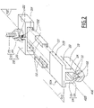
- the ROCS 100 is further detailed with reference to figure 2 .
- the contact wire 110 presents a globally round profile, with two slits 112 configured to cooperate with clamping tips of the busbar 120, as described later.
- the busbar 120 comprises a base plate 122, which is configured to cooperate with the hanger clamps 120.
- the base plate 122 has flat and elongated shape, that extends along a median plane P122 and that is arranged along the longitudinal axis A120 of the busbar 120.
- the medial plane P122 is supposed to be horizontal.
- the base plate 122 comprises two side edges 122A and 122B, which are parallel to a longitudinal plane P120, which is orthogonal to the median plane P122 and parallel to the longitudinal axis A120.
- the busbar 120 further comprises two holding arms 124.
- the holding arms 124 extend from the base plate 122 on the same side of the median plan P122, here from a downward side of the base 122.
- Each holding arm 124 comprises a main portion 126 and a clamping portion 128.
- the main portions 126 are parallel to the longitudinal plane P120.
- the two clamping portion 128 converge toward each other and comprise each a clamping tip 130, which cooperate with a respective slit 112 of the contact wire 110.
- the hanger clamp 200 comprises a connecting portion 210 and a clamping portion 220. Only a threaded portion 212 and a nut 214 of the connecting portion 210 are represented on figure 2 .
- the connecting portion 210 is configured to cooperate with an element of the railtrack 2, such as a beam or a tunnel ceiling, etc., in order to connect the clamping portion 220 to the railtrack 2, in particular in order to adjust the height of the clamping portion 220 above the railtrack 2.
- an element of the railtrack 2 such as a beam or a tunnel ceiling, etc.
- the clamping portion 220 is made of metallic lightweight material such as an aluminum alloy.
- the clamping portion 220 is configured to receive the base plate 122 of the busbar 120. In other words, the clamping portion 220 is configured to connect said base plate 122 to a fixed element of the railtrack 2.
- the clamping portion 220 When the base plate 122 is received in the clamping portion 220, the clamping portion 220 extends along a plane that is aligned with the median plane P122, and the clamping portion 220 has a cylindrical shape, with a rectangular cross section, extending along an axis that is parallel to the longitudinal axis A120.
- the clamping portion 220 comprises two jaws 222.
- the two jaws 222 have preferably the same shape and are reversibly assembled to each other with fixing organs 224, such as nuts and bolts.
- the two jaws 222 are arranged symmetrically from each other apart the longitudinal plane P120.
- Each jaw 222 has a cylindrical shape with a "U” profile extending along the longitudinal axis A120, the jaws 222 facing each other with the opening of the "U” being oriented toward the longitudinal plane P120.
- Each jaw 222 defines a reception volume V222, configured to receive a respective side edge 122A or 122B of the base plate 122.
- the hanger clamp 200 further comprises two inserts 230, each insert 230 being received within the reception volume V222 of a respective jaw 222.
- each insert 230 has a cylindrical shape with a "U" profile extending along the longitudinal axis A120 in the mounted configuration of the hanger clamp 200.
- the inserts 230 are sandwiched between the base plate 122 and the jaws 222, so that the base plate 122 does not contact directly the jaws 222.
- the inserts 230 are in contact with the base plate 122 without pressing on the surface of the base plate 122, so that translation movements of the base plate 122 relative to the hanger clamp 200 along any direction radial to the longitudinal axis A120 are prevented, while translation movements the base plate 122 relative to the hanger clamp 200 along the longitudinal axis A120 are allowed.
- the base plate 122 is just leaning on the inserts 230 without additional forces except the busbar 120 own weight.
- an air gap is arranged between the inserts 230 and the surface of the base plate 122. The air gap allows the free sliding of the busbar 120 relative to the clamping portion 220, and also the free orientation of the busbar 120 when the busbar 120 is curved, for example to follow curved tracks and for staggering.
- Each insert 230 is received within a respective reception volume V222 and is configured to be positioned between the corresponding jaw 222 and the base plate 122, while allowing sliding movements of the busbar 120 relative to the hanger clamp 200 along the longitudinal axis A120.
- the inserts 230 are mare from a material comprising synthetic polymer, that is selected for a low friction coefficient and high wear resistance, so that when the inserts 230 is in contact with a surface of the base plate 122, sliding movements of the busbar 120 relative to the hanger clamp 200 along the longitudinal axis A120 are allowed.
- Each insert 230 is also configured to conduct electricity between the base plate 122 and the clamping portion 220.
- Synthetic polymers used in railroad applications are usually electrically insulating.
- the material of the inserts 230 comprises a conductive charge, so that the material of the inserts 230 is conductive enough so the clamping portion 220 and the busbar 120 have the same electric potential.
- a charge is a mass of material, usually in the shape of fine powder or fibers, that is dispersed in a polymer material to reduce the cost and/or to adjust the properties of said polymer material, for example to adjust mechanical properties, density, thermal resistance, etc.
- the material of the inserts 230 has an electrical resistance lower than 10 k ⁇ - kilo-ohms -, preferably lower than 1.5 k ⁇ .
- the inserts 230 are configured to conduct electricity between the base plate 122 and the clamping portion 220.
- the conductive charge is preferably in the shape of fiber, to contribute also to the strength of the material of the inserts 230. More preferably, the conductive charge comprises carbon fibers, which are electrically conductive and contribute to improve the tensile strength of the polymer material.
- the polymer material of the inserts 230 is preferably a thermoplastic polymer. Compared to other types of polymers, such as thermosetting polymers, thermoplastic polymers show a better mechanical behavior in terms of wear resistance, toughness or thermal resistance.
- thermoplastic polymer for the material of the inserts 230 is polyamide.
- Raw materials comprising polyamide with carbon fibers added as a charge are, for example, commercially available from LATI Company under the brand name "LatiOhm”.
Landscapes
- Engineering & Computer Science (AREA)
- Mechanical Engineering (AREA)
- Current-Collector Devices For Electrically Propelled Vehicles (AREA)
Priority Applications (1)
| Application Number | Priority Date | Filing Date | Title |
|---|---|---|---|
| EP21315051.9A EP4063185A1 (de) | 2021-03-24 | 2021-03-24 | Aufhängeklemme zum halten eines leitenden profils, starres oberleitungssystem und schienensystem mit einer solchen aufhängeklemme |
Applications Claiming Priority (1)
| Application Number | Priority Date | Filing Date | Title |
|---|---|---|---|
| EP21315051.9A EP4063185A1 (de) | 2021-03-24 | 2021-03-24 | Aufhängeklemme zum halten eines leitenden profils, starres oberleitungssystem und schienensystem mit einer solchen aufhängeklemme |
Publications (1)
| Publication Number | Publication Date |
|---|---|
| EP4063185A1 true EP4063185A1 (de) | 2022-09-28 |
Family
ID=75639847
Family Applications (1)
| Application Number | Title | Priority Date | Filing Date |
|---|---|---|---|
| EP21315051.9A Pending EP4063185A1 (de) | 2021-03-24 | 2021-03-24 | Aufhängeklemme zum halten eines leitenden profils, starres oberleitungssystem und schienensystem mit einer solchen aufhängeklemme |
Country Status (1)
| Country | Link |
|---|---|
| EP (1) | EP4063185A1 (de) |
Citations (5)
| Publication number | Priority date | Publication date | Assignee | Title |
|---|---|---|---|---|
| DE102010033451A1 (de) * | 2010-08-05 | 2012-02-09 | Furrer + Frey Ag | Stromschienenanordnung |
| CN102785590A (zh) * | 2012-08-28 | 2012-11-21 | 浙江旺隆轨道交通设备有限公司 | 一种无螺栓汇流排弹性线夹 |
| CN202782747U (zh) | 2012-08-28 | 2013-03-13 | 浙江旺隆轨道交通设备有限公司 | 一种无螺栓汇流排弹性线夹 |
| KR20170043437A (ko) * | 2015-10-13 | 2017-04-21 | 엘에스전선 주식회사 | 신축이음장치 |
| EP3102458B1 (de) * | 2014-02-05 | 2018-06-06 | Rail Power Systems GmbH | Befestigungsvorrichtung für eine stromschiene und fahrleitungssystem |
-
2021
- 2021-03-24 EP EP21315051.9A patent/EP4063185A1/de active Pending
Patent Citations (5)
| Publication number | Priority date | Publication date | Assignee | Title |
|---|---|---|---|---|
| DE102010033451A1 (de) * | 2010-08-05 | 2012-02-09 | Furrer + Frey Ag | Stromschienenanordnung |
| CN102785590A (zh) * | 2012-08-28 | 2012-11-21 | 浙江旺隆轨道交通设备有限公司 | 一种无螺栓汇流排弹性线夹 |
| CN202782747U (zh) | 2012-08-28 | 2013-03-13 | 浙江旺隆轨道交通设备有限公司 | 一种无螺栓汇流排弹性线夹 |
| EP3102458B1 (de) * | 2014-02-05 | 2018-06-06 | Rail Power Systems GmbH | Befestigungsvorrichtung für eine stromschiene und fahrleitungssystem |
| KR20170043437A (ko) * | 2015-10-13 | 2017-04-21 | 엘에스전선 주식회사 | 신축이음장치 |
Non-Patent Citations (1)
| Title |
|---|
| ANONYMOUS: "Polytetrafluoroethylene (PTFE)", WIKIPEDIA, 1 January 2021 (2021-01-01), XP055785677, Retrieved from the Internet <URL:https://en.wikipedia.org/wiki/Polytetrafluoroethylene> [retrieved on 20210315] * |
Similar Documents
| Publication | Publication Date | Title |
|---|---|---|
| KR101746285B1 (ko) | 강체전차선용 지지클램프 | |
| KR101902361B1 (ko) | 강체 전차 선로용 절연구분장치 | |
| KR200497341Y1 (ko) | 강체전차선용 지지클램프 | |
| US9845025B2 (en) | Rigid T-rail conductor system | |
| EP4063185A1 (de) | Aufhängeklemme zum halten eines leitenden profils, starres oberleitungssystem und schienensystem mit einer solchen aufhängeklemme | |
| US20150246623A1 (en) | Hanger wire for contact wires of railway electrical lines | |
| KR101910230B1 (ko) | 강체전차선 연결구조 | |
| CN115742884B (zh) | 基于弹簧和阻尼电刷的刚性悬挂接触网系统 | |
| KR20130087778A (ko) | 신축이음장치 | |
| US4146119A (en) | Impact-resistant carbon current collectors | |
| US4187934A (en) | Section insulator for catenary systems | |
| US4250982A (en) | Section insulator for catenary systems | |
| US1336503A (en) | Catenary suspension system for electric railways | |
| KR20170058766A (ko) | 강체전차선 및 그 연결구조 | |
| EP4194260B1 (de) | Sammelschiene zum halten eines kontaktdrahts, starres oberleitungssystem und bahngleis mit solch einer sammelschiene | |
| US5676224A (en) | Electrical collector shoe assembly | |
| US4363939A (en) | Electrical supply line for the supply or current to railway vehicles | |
| EP3922508A1 (de) | Isolierträgeranordnung für eine fahrleitung zum antrieb eines elektrofahrzeugs, insbesondere einer strassenbahn oder eines fahrleitungsomnibusses sowie zugehörige fahrleitung | |
| KR20170039432A (ko) | 강체전차선 | |
| CN210437044U (zh) | 空中列车用接触轨膨胀接头 | |
| KR20180075189A (ko) | 고속용 강체전차선 이행장치 | |
| KR101264312B1 (ko) | 1열 구조로 구성된 교류/직류 구분용 절연구분장치 | |
| CN217804406U (zh) | 具有汇流排滑动功能的干线铁路接触网悬挂定位系统 | |
| KR101269230B1 (ko) | 철도차량용 도전레일설비 | |
| US1157392A (en) | Trolley-conductor. |
Legal Events
| Date | Code | Title | Description |
|---|---|---|---|
| PUAI | Public reference made under article 153(3) epc to a published international application that has entered the european phase |
Free format text: ORIGINAL CODE: 0009012 |
|
| STAA | Information on the status of an ep patent application or granted ep patent |
Free format text: STATUS: THE APPLICATION HAS BEEN PUBLISHED |
|
| STAA | Information on the status of an ep patent application or granted ep patent |
Free format text: STATUS: REQUEST FOR EXAMINATION WAS MADE |
|
| AK | Designated contracting states |
Kind code of ref document: A1 Designated state(s): AL AT BE BG CH CY CZ DE DK EE ES FI FR GB GR HR HU IE IS IT LI LT LU LV MC MK MT NL NO PL PT RO RS SE SI SK SM TR |
|
| 17P | Request for examination filed |
Effective date: 20220906 |
|
| RBV | Designated contracting states (corrected) |
Designated state(s): AL AT BE BG CH CY CZ DE DK EE ES FI FR GB GR HR HU IE IS IT LI LT LU LV MC MK MT NL NO PL PT RO RS SE SI SK SM TR |
|
| P01 | Opt-out of the competence of the unified patent court (upc) registered |
Effective date: 20230823 |
|
| RAP1 | Party data changed (applicant data changed or rights of an application transferred) |
Owner name: ALSTOM HOLDINGS |
|
| INTG | Intention to grant announced |
Effective date: 20240621 |